EP1780480A1 - Heat exchanger and stirling engine - Google Patents
Heat exchanger and stirling engine Download PDFInfo
- Publication number
- EP1780480A1 EP1780480A1 EP05739216A EP05739216A EP1780480A1 EP 1780480 A1 EP1780480 A1 EP 1780480A1 EP 05739216 A EP05739216 A EP 05739216A EP 05739216 A EP05739216 A EP 05739216A EP 1780480 A1 EP1780480 A1 EP 1780480A1
- Authority
- EP
- European Patent Office
- Prior art keywords
- coating layer
- corrugated fin
- heat
- heat exchanger
- cylindrical member
- Prior art date
- Legal status (The legal status is an assumption and is not a legal conclusion. Google has not performed a legal analysis and makes no representation as to the accuracy of the status listed.)
- Withdrawn
Links
Images


Classifications
-
- F—MECHANICAL ENGINEERING; LIGHTING; HEATING; WEAPONS; BLASTING
- F28—HEAT EXCHANGE IN GENERAL
- F28F—DETAILS OF HEAT-EXCHANGE AND HEAT-TRANSFER APPARATUS, OF GENERAL APPLICATION
- F28F13/00—Arrangements for modifying heat-transfer, e.g. increasing, decreasing
- F28F13/18—Arrangements for modifying heat-transfer, e.g. increasing, decreasing by applying coatings, e.g. radiation-absorbing, radiation-reflecting; by surface treatment, e.g. polishing
-
- F—MECHANICAL ENGINEERING; LIGHTING; HEATING; WEAPONS; BLASTING
- F25—REFRIGERATION OR COOLING; COMBINED HEATING AND REFRIGERATION SYSTEMS; HEAT PUMP SYSTEMS; MANUFACTURE OR STORAGE OF ICE; LIQUEFACTION SOLIDIFICATION OF GASES
- F25B—REFRIGERATION MACHINES, PLANTS OR SYSTEMS; COMBINED HEATING AND REFRIGERATION SYSTEMS; HEAT PUMP SYSTEMS
- F25B9/00—Compression machines, plants or systems, in which the refrigerant is air or other gas of low boiling point
- F25B9/12—Compression machines, plants or systems, in which the refrigerant is air or other gas of low boiling point using 3He-4He dilution
-
- F—MECHANICAL ENGINEERING; LIGHTING; HEATING; WEAPONS; BLASTING
- F02—COMBUSTION ENGINES; HOT-GAS OR COMBUSTION-PRODUCT ENGINE PLANTS
- F02G—HOT GAS OR COMBUSTION-PRODUCT POSITIVE-DISPLACEMENT ENGINE PLANTS; USE OF WASTE HEAT OF COMBUSTION ENGINES; NOT OTHERWISE PROVIDED FOR
- F02G1/00—Hot gas positive-displacement engine plants
- F02G1/04—Hot gas positive-displacement engine plants of closed-cycle type
- F02G1/043—Hot gas positive-displacement engine plants of closed-cycle type the engine being operated by expansion and contraction of a mass of working gas which is heated and cooled in one of a plurality of constantly communicating expansible chambers, e.g. Stirling cycle type engines
- F02G1/053—Component parts or details
- F02G1/055—Heaters or coolers
-
- F—MECHANICAL ENGINEERING; LIGHTING; HEATING; WEAPONS; BLASTING
- F25—REFRIGERATION OR COOLING; COMBINED HEATING AND REFRIGERATION SYSTEMS; HEAT PUMP SYSTEMS; MANUFACTURE OR STORAGE OF ICE; LIQUEFACTION SOLIDIFICATION OF GASES
- F25B—REFRIGERATION MACHINES, PLANTS OR SYSTEMS; COMBINED HEATING AND REFRIGERATION SYSTEMS; HEAT PUMP SYSTEMS
- F25B9/00—Compression machines, plants or systems, in which the refrigerant is air or other gas of low boiling point
-
- F—MECHANICAL ENGINEERING; LIGHTING; HEATING; WEAPONS; BLASTING
- F28—HEAT EXCHANGE IN GENERAL
- F28F—DETAILS OF HEAT-EXCHANGE AND HEAT-TRANSFER APPARATUS, OF GENERAL APPLICATION
- F28F1/00—Tubular elements; Assemblies of tubular elements
- F28F1/10—Tubular elements and assemblies thereof with means for increasing heat-transfer area, e.g. with fins, with projections, with recesses
- F28F1/105—Tubular elements and assemblies thereof with means for increasing heat-transfer area, e.g. with fins, with projections, with recesses the means being corrugated elements extending around the tubular elements
Definitions
- the present invention relates to a heat exchanger and to a Stirling engine including the heat exchanger, and particularly, to a connection structure between a heat exchanging member and an outer shell body (a cylindrical member) constituting a heat exchanger.
- Japanese Patent Laying-Open No. 2001-91075 describes a heat exchanger for a Stirling engine, which includes a cylindrical member and a corrugated fin as a heat exchanging member.
- the corrugated fin is mounted inside the cylindrical member.
- a ring-like member is used to press the corrugated fin toward the cylindrical member, whereby the corrugated fin is attached with applying pressure to the cylindrical member.
- Japanese Patent Laying-Open No. 2003-251459 describes a heat exchanger of a refrigerator wherein a heat exchanging member is attached to the inside of a cylindrical case.
- a plating layer is formed on at least one of an outer circumferential surface of the heat exchanging member and an inner circumferential surface of the cylindrical case.
- Eutectic alloy produced from eutectic reaction with the plating layer bonds the cylindrical case and the heat exchanging member at a heat transfer interface therebetween.
- Patent Document 1 Japanese Patent Laying-Open No. 2001-091075
- Patent Document 2 Japanese Patent Laying-Open No. 2003-251459
- the present invention has been made to solve problems such as described above, and an object thereof is to provide a heat exchanger with which a contacting area between a heat exchanging member and an outer shell body to which the heat exchanging member is attached can be increased, and a Stirling engine including the heat exchanger.
- a heat exchanger includes, in one aspect, an outer shell body made of metal, a heat exchanging member that is made of metal and that is attached to a circumferential surface of the outer shell body, and a coating layer formed on at least one of the circumferential surface of the outer shell body and a circumferential surface of the heat exchanging member.
- the heat exchanging member is pressure-contacted to the outer shell body.
- a "heat exchanging member” refers to a member that has a function of conducting heat exchange with a working medium or the like.
- the coating layer may at least partially coat the circumferential surface of the outer shell body and/or the circumferential surface of the heat exchanging member.
- the coating layer is lower in hardness than at least one of the outer shell body and the heat exchanging member.
- a material other than metal can be employed if it has an excellent heat conductivity.
- an alloy layer may be formed between the outer shell body and the heat exchanging member, which is formed by alloying of the metal material constituting the coating layer and a metal material constituting at least one of the outer shell body and the heat exchanging member. The coating layer may be melted and thereafter solidified.
- a heat exchanger includes, in the other aspect, an outer shell body made of metal, and a heat exchanging member that is constituted of a copper material containing copper by at least 99.99 % or of a copper material containing at least one of silver and tin, and that is attached to the outer shell body.
- a circumferential surface of the heat exchanging member is pressure-contacted to the circumferential surface of the outer shell body. That is, in the present aspect, a material that is excellent not only in heat conductivity but also in ductility is employed as the material of the heat exchanging member.
- the outer shell body may be constituted of a cylindrical member, for example.
- the heat exchanging member may be constituted of a corrugated fin, for example.
- the heat exchanging member is attached to the inside of the outer shell body.
- a Stirling engine according to the present invention includes the heat exchanger as described above.
- the heat exchanging member is pressure-contacted to the outer shell body, and therefore a contacting area between the heat exchanging member and/or outer shell body and the coating layer can be increased as compared to a case where the heat exchanging member and/or the outer shell body simply abuts on the coating layer.
- the coating layer is formed on at least one of the surface of the outer shell body and the surface of the heat exchanging member, and therefore it implements part of the heat exchanging member and/or the outer shell body. Accordingly, the contacting area between the heat exchanging member and/or the outer shell body and the coating layer increases, and consequently the contacting area between the heat exchanging member and the outer shell body can be increased.
- a copper material containing copper by at least 99.99 % or a copper material containing at least one of silver and tin is employed as a material of the heat exchanging member.
- ductility of the heat exchanging member itself can be improved. This can increase the degree of deformation of the heat exchanging member at the contacting portion between the heat exchanging member and the outer shell body when the heat exchanging member is pressure-contacted to the outer shell body. In this case also, the contacting area between the heat exchanging member and the outer shell body can be increased.
- the Stirling engine of the present invention includes the heat exchanger as described above, such a Stirling engine can be provided that includes the heat exchanger of high performance and where provision of the contacting area between the heat exchanging member and the outer shell body is ensured.
- 1, 1A, 1B heat exchanger 2 corrugated fin; 2a outer circumferential portion; 2b inner circumferential portion; 3 ring-like member; 4 cylindrical member; 5 coating layer; 7 Stirling engine; 8 tube; 12 casing; 13 cylinder; 14 piston; 15 displacer; 16 regenerator; 17 working space; 17A compression space; 17B expansion space; 18 heat dissipating portion; 19 heat absorbing portion; 20 inner yoke; 21 movable magnet portion; 22 outer yoke; 23 linear motor; 24 piston spring; 25 displacer spring; 26 displacer rod; and 27 back-pressure space.
- Fig. 1 is a perspective view of a heat exchanger 1 of a first embodiment of the present invention.
- Fig. 2 is a partial enlarged view of heat exchanger 1 shown in Fig. 1.
- the heat exchanger of the first embodiment includes: a cylindrical or bottomed cylindrical outer shell body made of metal; a heat exchanging member that is made of metal and that is attached to an inner circumferential surface of the outer shell body; and a coating layer formed on at least one of the inner circumferential surface of the outer shell body and an outer surface of the heat exchanging member.
- heat exchanger 1 includes: a cylindrical or bottomed cylindrical member 4 made of metal as the outer shell body (a member implementing a heat dissipating portion or a heat absorbing portion: hereinafter referred to as a cylindrical member); a corrugated fin 2 that is made of metal and that is attached to cylindrical member 4 as the heat exchanging member; and a ring-like member 3 made of metal.
- Cylindrical member 4 can be constituted of a metal material (including alloy) with an excellent heat conductivity, for example, copper (Cu), copper alloy, stainless steel, aluminum (Al), aluminum alloy and the like, or a composite material of a combination of such materials.
- Corrugated fin 2 is a member carrying out heat exchange with a working medium, with its outer diameter being designed to be substantially the same as the inner diameter of cylindrical member 4.
- Corrugated fin 2 can be manufactured from copper or copper alloy, for example.
- Ring-like member 3 mainly has a function of pressing corrugated fin 2 against the inner circumferential surface of cylindrical member 4 to fix the same.
- Ring-like member 3 may be constituted of the same material as cylindrical member 4, or of a different material therefrom.
- ring-like member 3 may be constituted of a material that is higher in hardness than a material of corrugated fin 2.
- Ring-like member 3 typically has the outer diameter slightly greater than the inner diameter of corrugated fin 2, and pressed in inside corrugated fin 2 after corrugated fin 2 is attached to the inside of cylindrical member 4.
- corrugated fin 2 has an outer circumferential portion 2a, an inner circumferential portion 2b, and a connecting portion connecting outer circumferential portion 2a and inner circumferential portion 2b and extending in the radial direction of cylindrical member 4.
- Corrugated fin 2 is shaped to be regularly concave and convex in its circumferential direction.
- Outer circumferential portion 2a of corrugated fin 2 is pressure-contacted to coating layer 5 on the inner circumferential surface of cylindrical member 4, while inner circumferential portion 2b of corrugated fin 2 is pressure-contacted to the outer circumferential surface of ring-like member 3.
- coating layer 5 is typically constituted of metal, a material other than metal can be used. When coating layer 5 is to be constituted of metal, it can be formed by a scheme such as plating or deposition. For example, gold (Au) that is excellent in ductility and heat conductivity may be used as coating layer 5. While coating layer 5 may typically be formed in about some ⁇ m thickness on the entire inner circumferential surface of cylindrical member 4, it can selectively be formed only at the necessary position. Coating layer 5 may be constituted of a single layer structure or a stacked structure of a plurality of layers. When coating layer 5 is constituted of a stacked structure of a plurality of layers, each layer may be the same or different in material, hardness, thickness and the like.
- the heat exchanging member is attached to the outer shell body so that the coating layer is deformed.
- corrugated fin 2 is attached to the inside of cylindrical member 4 so that coating layer 5 is deformed.
- corrugated fin 2 may be pressed in inside cylindrical member 4 to thereby deform coating layer 5.
- coating layer 5 can be deformed by outer circumferential portion 2a of corrugated fin 2.
- corrugated fin 2 is attached with applying force pressure to cylindrical member 4 so that coating layer 5 is deformed as described above, it becomes possible to attach corrugated fin 2 to cylindrical member 4 with deformed coating layer 5 interposed therebetween, and also coating layer 5 can be arranged around the contacting portion between corrugated fin 2 and cylindrical member 4. In either manners, the contacting area between corrugated fin 2 and coating layer 5 can be increased as compared to a manner where a corrugated fin 2 is simply abutted on coating layer 5. Not only that, by compression and deformation of coating layer 5, a small gap between coating layer 5 and corrugated fin 2 and/or cylindrical member 4 can be reduced. This can also contribute to an increase in the contacting area between corrugated fin 2 and cylindrical member 4.
- coating layer 5 may set to be lower in hardness than at least one of corrugated fin 2 and cylindrical member 4, preferably than corrugated fin 2.
- coating layer 5 can easily be deformed but also the contacting area between corrugated fin 2 and coating layer 5 can further be increased.
- Fig. 3 is an enlarged view of a joining portion (abutting portion) between outer circumferential portion 2a of corrugated fin 2 and the inner circumferential portion of cylindrical member 4 in Fig. 2.
- coating layer 5 is compressed and deformed between corrugated fin 2 and cylindrical member 4, it becomes possible to allow coating layer 5 to enter a small gap that possibly exists near the surface of outer circumferential portion 2a of corrugated fin 2 or near the inner circumferential surface of cylindrical member 4. This can also effectively contribute to an increase in the contacting area between corrugated fin 2 and cylindrical member 4.
- Fig. 4 is a modification of the first embodiment.
- coating layer 5 in the state of Fig. 3 is heated and melted, and thereafter solidified.
- coating layer 5 in addition to a further increase in the contacting area between corrugated fin 2 and coating layer 5, a further reduction in the aforementioned small gap that possibly exists between outer circumferential portion 2a of corrugated fin 2 and cylindrical member 4 can be attained.
- coating layer 5 near corrugated fin 2 can be adhered to the surface of corrugated fin 2 when melted, and the contacting area can further be increased.
- the metal material constituting coating layer 5 and the material constituting at least one of corrugated fin 2 and cylindrical member 4 can be alloyed to form an alloy layer.
- the metal material constituting coating layer 5 and the material constituting at least one of corrugated fin 2 and cylindrical member 4 can be alloyed to form an alloy layer.
- the metal material constituting coating layer 5 and the material constituting at least one of corrugated fin 2 and cylindrical member 4 can be alloyed to form an alloy layer.
- an alloy layer can be formed between corrugated fin 2 and cylindrical member 4.
- coating layer 5 As the material of coating layer 5, a solder material (Sn-Ag base solder material, a lead-free solder material and the like) in addition to the materials noted above can be used.
- solder material Sn-Ag base solder material, a lead-free solder material and the like
- the alloying temperature can be reduced to about 220°C.
- the coating layer is formed on the heat exchanging member side. Specifically, above-described coating layer 5 is formed on the surface of corrugated fin 2 as shown in Fig. 5.
- the rest of the configuration is basically the same as in the first embodiment. The effect similar to that in the first embodiment can also be expected in the second embodiment.
- Fig. 6 shows an enlarged view of the joining portion (abutting portion) of outer circumferential portion 2a of corrugated fin 2 and the inner circumferential portion of cylindrical member 4 in Fig. 5.
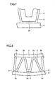
- Fig. 7 shows a modification of the second embodiment.
- coating layer 5 in the state shown in Fig. 6 may be heated and melted, and thereafter solidified.
- coating layer 5 near cylindrical member 4 can be adhered to the surface of cylindrical member 4. This can ensure provision of a contacting area equal to or greater than that in the example of Fig. 6.
- the aforementioned small gap between outer circumferential portion 2a of corrugated fin 2 and cylindrical member 4 can further be reduced.
- an alloy layer may be formed, which is formed by alloying of the metal material constituting coating layer 5 and the material constituting at least one of corrugated fin 2 and cylindrical member 4 when coating layer 5 is melted.
- the specific material for each element may be the same as in the first embodiment.
- Coating layer 5 of a single layer or a plurality of layers may be formed on the surface of both of outer circumferential portion 2a of corrugated fin 2 and cylindrical member 4.
- the coating layer is selectively formed on at least one of the surface of the outer shell body and the surface of the heat exchanging member. Specifically, the coating layer is selectively formed at and near the joining portion of the outer shell body and the heat exchanging member.
- coating layer 5 is formed only between outer circumferential portion 2a of corrugated fin 2 and cylindrical member 4.
- Coating layer 5 may be formed to at least one of corrugated fin 2 and cylindrical member 4.
- the contacting area between corrugated fin 2 and/or cylindrical member 4 and coating layer 5 can be increased, while a small gap between corrugated fin 2 and cylindrical member 4 can be reduced.
- coating layer 5 may be deformed and melted, and thereafter solidified.
- the effect similar to that in the first and second embodiments can be expected.
- a fourth embodiment of the present invention While in each of the above-described embodiment the coating layer is formed between the outer shell body and the heat exchanging member, in the fourth embodiment the ductility of the heat exchanging member itself is improved without forming such a coating layer.
- Fig. 9 is a partial enlarged view of a heat exchanger 1 of the fourth embodiment of the present invention.
- a coating layer is not formed between outer circumferential portion 2a of corrugated fin 2 and cylindrical member 4, and outer circumferential portion 2a of corrugated fin 2 and cylindrical member 4 directly contact to each other.
- the ductility of corrugated fin 2 itself is improved.
- improvement of the ductility of corrugated fin 2 may be attained by increasing the purity of the material.
- addition of another material to the material mainly constituting corrugated fin 2 may improve the ductility.
- corrugated fin 2 when corrugated fin 2 is constituted of copper, by producing corrugated fin 2 using a copper material containing copper by at least 99.99 %, the ductility of corrugated fin 2 itself can be improved.
- corrugated fin 2 when corrugated fin 2 is constituted of a material including copper and a metal material other than copper, corrugated fin 2 may be constituted of a copper material (i.e., the material containing copper as the main component) containing materials other than copper such as silver or tin.
- the material such as silver or tin by adding the material such as silver or tin to the main component of copper, the ductility of the copper material can be improved.
- corrugated fin 2 By improving the ductility of the corrugated fin 2 itself as above, corrugated fin 2 can easily be deformed when it is attached to cylindrical member 4. Thus, corrugated fin 2 can be deformed so as to conform to the inner circumferential surface of cylindrical member 4 at positions where corrugated fin 2 is pressure-contacted to the inner circumferential surface of cylindrical member 4, whereby the contacting area between corrugated fin 2 and cylindrical member 4 can be increased.
- the heat exchanger according to the above-described embodiments is incorporated into a Stirling engine.
- a Stirling engine 7 includes a casing 12, a cylinder 13 attached to casing 12, a piston 14 and a displacer 15 reciprocating inside cylinder 13, a regenerator 16, a working space 17 including a compression space 17A and an expansion space 17B, a heat dissipating portion 18 (warm head), a heat absorbing portion 19 (cold head), a linear motor 23 as piston driving means, a piston spring 24, a displacer spring 25, a displacer rod 26 and a back-pressure space 27.
- Stirling engine 7 is filled with a working medium such as helium gas, hydrogen gas, nitride gas or the like.
- Cylinder 13 has a substantially cylindrical shape, and internally receives piston 14 and displacer 15 so that they can reciprocate.
- piston 14 and displacer 15 are arranged coaxially with a distance from each other, and divide working space 17 into compression space 17A and expansion space 17B. More specifically, working space 17 positions on displacer 15 side relative to the end surface of piston 14 facing displacer 15.
- Compression space 17A is formed between piston 14 and displacer 15, and expansion space 17B is formed between displacer 15 and heat absorbing portion 19.
- Compression space 17A is enclosed mainly by heat dissipating portion 18, and expansion space 17B is enclosed mainly by heat absorbing portion 19.
- regenerator 16 wherein a film is wound with prescribed intervals on the inner circumferential surface of tube 8, is arranged, through which compression space 17A and expansion space 17B communicate.
- the working medium enclosed in the closed circuit flows in accordance with the operation of piston 14 and displacer 15, whereby the reverse Stirling cycle is realized.
- Linear motor 23 is arranged in back-pressure space 27 positioned outside cylinder 13.
- Linear motor 23 has an inner yoke 20, a movable magnet portion 21, and an outer yoke 22.
- Linear motor 23 drives piston 14 in the axial direction of cylinder 13.
- Piston 14 has its one end connected to piston spring 24 that is constituted of a leaf spring or the like. Piston spring 24 functions as elastic force providing means for providing elastic force to piston 14. By providing the elastic force by piston spring 24 piston 14 is allowed to cyclically reciprocate in cylinder 13 stably.
- Displacer 15 has its one end connected to displacer spring 25 with displacer rod 26 interposed therebetween. Displacer rod 26 is arranged to penetrate through piston 14.
- Displacer spring 25 is constituted of a leaf spring or the like. The peripheral portion of displacer spring 25 and the peripheral portion of piston spring 24 are supported by a supporting member extending from linear motor 23 toward back-pressure space 27.
- Back-pressure space 27 enclosed by casing 12 is arranged opposite to displacer 15 relative to piston 14.
- Back-pressure space 27 includes an outer circumferential region positioned around piston 14 in casing 12 and a rear region positioned closer to piston spring 24 side than to piston 14 in casing 12 (rear side). Inside back-pressure space 27 also, the working medium exists.
- Heat dissipating portion 18 and heat absorbing portion 19 are provided with a heat exchanger 1 A (a high-temperature side heat exchanger) and a heat exchanger 1B (a low-temperature side heat exchanger), respectively.
- heat exchangers 1A and 1B the heat exchangers described in the embodiments are used. That is, on the inner circumferential surface of heat dissipating portion 18 and heat absorbing portion 19, the outer circumferential surface of corrugated fin 2 is connected (joined) by the schemes described in the embodiments.
- the contacting area between heat dissipating portion 18, heat absorbing portion 19 and corrugated fin 2 can be increased. That is, a sufficient contacting area between the heat exchanging member and the outer shell body in the heat exchanger can be provided. Accordingly, the heat resistance in the heat exchanger can be reduced, and heat transfer loss can be reduced. As a result, a Stirling engine with a heat exchanger of high performance where heat resistance is reduced can be obtained. When it is used for a refrigerator for example, the refrigeration capacity can be improved.
- linear motor 23 is actuated to drive piston 14.
- Piston 14 driven by linear motor 23 approaches displacer 15 and compresses the working medium (working gas) in compression space 17A.
- Piston 14 approaches displacer 15, whereby the temperature of the working medium in compression space 17A is increased.
- the heat is transferred via heat exchanger 1A to heat dissipating portion 18, which in turn dissipates heat generated inside compression space 17A to the outside.
- the temperature of the working medium inside compression space 17A is maintained substantially isothermal. That is, this process corresponds to the isothermal compression process in the reverse Stirling cycle.
- displacer 15 moves toward piston 14 side (the side of the rear end of a vessel portion of casing 12).
- a center portion of displacer spring 25 also deforms so as to project toward the rear side.
- expansion space 17B As described above, by the expansion of the working medium in expansion space 17B, the temperature of the working medium in expansion space 17B is reduced. On the other hand, the outside heat is transferred to expansion space 17B by heat absorbing portion 19, and therefore expansion space 17 is maintained to be substantially isothermal. That is, this process corresponds to the isothermal expansion process in the reverse Stirling cycle.
- displacer 15 starts to move in the direction away from piston 14, whereby the working medium in expansion space 17B passes through regenerator 16 and returns again to compression space 17A side.
- the heat having been stored in regenerator 16 is provided to working medium, whereby the temperature of the working medium is increased. That is, this process corresponds to the isovolumic heating process of the reverse Stirling cycle.
- the series of processes isothermal compression process - isovolumic cooling process - isothermal expansion process - isovolumic heating process) is repeated to constitute the reverse Stirling cycle.
- the temperature of heat absorbing portion 19 gradually decreases to reach cryogenic temperature.
- the temperature of heat dissipating portion 18 gradually increases to reach a prescribed high temperature.
- heat exchangers 1A and 1B of the present embodiment heat from the working medium can efficiently be transferred to heat absorbing portion 19 and heat dissipating portion 18 via heat exchangers 1A and 1B.
- the present invention is effectively applicable to a heat exchanger and to a Stirling engine including the heat exchanger.
Landscapes
- Engineering & Computer Science (AREA)
- Mechanical Engineering (AREA)
- General Engineering & Computer Science (AREA)
- Physics & Mathematics (AREA)
- Thermal Sciences (AREA)
- Chemical & Material Sciences (AREA)
- Combustion & Propulsion (AREA)
- Geometry (AREA)
- Heat-Exchange Devices With Radiators And Conduit Assemblies (AREA)
Abstract
A heat exchanger includes: a cylindrical member (4) made of metal as an outer shell body; a corrugated fin (2) that is made of metal and that is attached to the cylindrical member (4) as a heat exchanging member; and a coating layer (5) formed on at least one of a surface of the cylindrical member (4) and a surface of the corrugated fin (2). The corrugated fin (2) is pressure-contacted to the cylindrical member (4). The heat exchanger can be provided, for example, to a heat absorbing portion or a heat dissipating portion of a Stirling engine.
Description
- The present invention relates to a heat exchanger and to a Stirling engine including the heat exchanger, and particularly, to a connection structure between a heat exchanging member and an outer shell body (a cylindrical member) constituting a heat exchanger.
- Conventionally, to a heat exchanger of a refrigerator and the like, a heat exchanging member for conducting heat exchange is attached. For example,
Japanese Patent Laying-Open No. 2001-91075 -
Japanese Patent Laying-Open No. 2003-251459
Patent Document 1:Japanese Patent Laying-Open No. 2001-091075
Patent Document 2:Japanese Patent Laying-Open No. 2003-251459 - On the other hand, it is difficult to ensure provision of a sufficient contacting area between the corrugated fin and the cylindrical member just by attaching the corrugated fin with applying pressure to the inner circumferential surface as in the heat exchanger of
Japanese Patent Laying-Open No. 2001-91075 - Even when eutectic alloy produced from eutectic reaction with the plating layer bonds the cylindrical case and the heat exchanging member at a heat transfer interface therebetween as in
Japanese Patent Laying-Open No. 2003-251459 Japanese Patent Laying-Open No. 2001-91075 - The present invention has been made to solve problems such as described above, and an object thereof is to provide a heat exchanger with which a contacting area between a heat exchanging member and an outer shell body to which the heat exchanging member is attached can be increased, and a Stirling engine including the heat exchanger.
- A heat exchanger according to the present invention includes, in one aspect, an outer shell body made of metal, a heat exchanging member that is made of metal and that is attached to a circumferential surface of the outer shell body, and a coating layer formed on at least one of the circumferential surface of the outer shell body and a circumferential surface of the heat exchanging member. The heat exchanging member is pressure-contacted to the outer shell body. In the present specification, a "heat exchanging member" refers to a member that has a function of conducting heat exchange with a working medium or the like. The coating layer may at least partially coat the circumferential surface of the outer shell body and/or the circumferential surface of the heat exchanging member.
- Preferably, the coating layer is lower in hardness than at least one of the outer shell body and the heat exchanging member. As to the coating layer, a material other than metal can be employed if it has an excellent heat conductivity. When the coating layer is constituted of a metal material, an alloy layer may be formed between the outer shell body and the heat exchanging member, which is formed by alloying of the metal material constituting the coating layer and a metal material constituting at least one of the outer shell body and the heat exchanging member. The coating layer may be melted and thereafter solidified.
- A heat exchanger according to the present invention includes, in the other aspect, an outer shell body made of metal, and a heat exchanging member that is constituted of a copper material containing copper by at least 99.99 % or of a copper material containing at least one of silver and tin, and that is attached to the outer shell body. A circumferential surface of the heat exchanging member is pressure-contacted to the circumferential surface of the outer shell body. That is, in the present aspect, a material that is excellent not only in heat conductivity but also in ductility is employed as the material of the heat exchanging member.
- The outer shell body may be constituted of a cylindrical member, for example. The heat exchanging member may be constituted of a corrugated fin, for example. Here, the heat exchanging member is attached to the inside of the outer shell body.
- A Stirling engine according to the present invention includes the heat exchanger as described above.
- With the heat exchanger in one aspect of the present invention, the heat exchanging member is pressure-contacted to the outer shell body, and therefore a contacting area between the heat exchanging member and/or outer shell body and the coating layer can be increased as compared to a case where the heat exchanging member and/or the outer shell body simply abuts on the coating layer. The coating layer is formed on at least one of the surface of the outer shell body and the surface of the heat exchanging member, and therefore it implements part of the heat exchanging member and/or the outer shell body. Accordingly, the contacting area between the heat exchanging member and/or the outer shell body and the coating layer increases, and consequently the contacting area between the heat exchanging member and the outer shell body can be increased.
- With the heat exchanger in the other aspect of the present invention, as a material of the heat exchanging member, a copper material containing copper by at least 99.99 % or a copper material containing at least one of silver and tin is employed. Thus, ductility of the heat exchanging member itself can be improved. This can increase the degree of deformation of the heat exchanging member at the contacting portion between the heat exchanging member and the outer shell body when the heat exchanging member is pressure-contacted to the outer shell body. In this case also, the contacting area between the heat exchanging member and the outer shell body can be increased.
- As the Stirling engine of the present invention includes the heat exchanger as described above, such a Stirling engine can be provided that includes the heat exchanger of high performance and where provision of the contacting area between the heat exchanging member and the outer shell body is ensured.
-
- Fig. 1 is a cross-sectional perspective view of a substantial part of a heat exchanger of a first embodiment of the present invention.
- Fig. 2 is a partial enlarged view of the heat exchanger shown in Fig. 1.
- Fig. 3 is a substantial part enlarged view of Fig. 2.
- Fig. 4 shows a modification of the structure shown in Fig. 3.
- Fig. 5 is a partial enlarged view of a heat exchanger of a second embodiment of the present invention.
- Fig. 6 is an enlarged view of a substantial part of Fig. 5.
- Fig. 7 shows a modification of the structure shown in Fig. 6.
- Fig. 8 is a partial enlarged view of a heat exchanger of a third embodiment of the present invention.
- Fig. 9 is a partial enlarged view of a heat exchanger of a fourth embodiment of the present invention.
- Fig. 10 is a cross-sectional view of a Stirling engine including the heat exchanger according to the present invention.
- 1, 1A, 1B heat exchanger; 2 corrugated fin; 2a outer circumferential portion; 2b inner circumferential portion; 3 ring-like member; 4 cylindrical member; 5 coating layer; 7 Stirling engine; 8 tube; 12 casing; 13 cylinder; 14 piston; 15 displacer; 16 regenerator; 17 working space; 17A compression space; 17B expansion space; 18 heat dissipating portion; 19 heat absorbing portion; 20 inner yoke; 21 movable magnet portion; 22 outer yoke; 23 linear motor; 24 piston spring; 25 displacer spring; 26 displacer rod; and 27 back-pressure space.
- In the following, referring to Figs. 1-10, embodiments of the present invention will be described.
- Fig. 1 is a perspective view of a heat exchanger 1 of a first embodiment of the present invention. Fig. 2 is a partial enlarged view of heat exchanger 1 shown in Fig. 1.
- The heat exchanger of the first embodiment includes: a cylindrical or bottomed cylindrical outer shell body made of metal; a heat exchanging member that is made of metal and that is attached to an inner circumferential surface of the outer shell body; and a coating layer formed on at least one of the inner circumferential surface of the outer shell body and an outer surface of the heat exchanging member. In the example of Fig. 1, heat exchanger 1 includes: a cylindrical or bottomed
cylindrical member 4 made of metal as the outer shell body (a member implementing a heat dissipating portion or a heat absorbing portion: hereinafter referred to as a cylindrical member); acorrugated fin 2 that is made of metal and that is attached tocylindrical member 4 as the heat exchanging member; and a ring-like member 3 made of metal. -
Cylindrical member 4 can be constituted of a metal material (including alloy) with an excellent heat conductivity, for example, copper (Cu), copper alloy, stainless steel, aluminum (Al), aluminum alloy and the like, or a composite material of a combination of such materials. - In the example of Fig. 1, inside
cylindrical member 4,corrugated fin 2 is attached.Corrugated fin 2 is a member carrying out heat exchange with a working medium, with its outer diameter being designed to be substantially the same as the inner diameter ofcylindrical member 4. Thus, by applying force to the inner circumferential ofcorrugated fin 2 with force in the externally radial direction ofcylindrical member 4, the outer circumferential surface ofcorrugated fin 2 can be pressed against the inner circumferential surface ofcylindrical member 4 and the outer circumferential surface of thecorrugated fin 2 can be pressure-contacted to the inner circumferential surface ofcylindrical member 4.Corrugated fin 2 can be manufactured from copper or copper alloy, for example. - Ring-
like member 3 mainly has a function of pressingcorrugated fin 2 against the inner circumferential surface ofcylindrical member 4 to fix the same. Ring-like member 3 may be constituted of the same material ascylindrical member 4, or of a different material therefrom. For example, ring-like member 3 may be constituted of a material that is higher in hardness than a material ofcorrugated fin 2. - Ring-
like member 3 typically has the outer diameter slightly greater than the inner diameter ofcorrugated fin 2, and pressed in insidecorrugated fin 2 aftercorrugated fin 2 is attached to the inside ofcylindrical member 4. Here, constituting ring-like member 3 of the material higher in hardness than the material ofcorrugated fin 2, the degree of deformation of ring-like member 3 when pressed in can be reduced, andcorrugated fin 2 can surely and effectively be provided with the force in the externally radial direction ofcylindrical member 4. - In the first embodiment, as shown in Fig. 2,
coating layer 5 is formed on the inner circumferential surface ofcylindrical member 4. As shown in Fig. 2,corrugated fin 2 has an outercircumferential portion 2a, an innercircumferential portion 2b, and a connecting portion connecting outercircumferential portion 2a and innercircumferential portion 2b and extending in the radial direction ofcylindrical member 4.Corrugated fin 2 is shaped to be regularly concave and convex in its circumferential direction. Outercircumferential portion 2a ofcorrugated fin 2 is pressure-contacted tocoating layer 5 on the inner circumferential surface ofcylindrical member 4, while innercircumferential portion 2b ofcorrugated fin 2 is pressure-contacted to the outer circumferential surface of ring-like member 3. - While
coating layer 5 is typically constituted of metal, a material other than metal can be used. When coatinglayer 5 is to be constituted of metal, it can be formed by a scheme such as plating or deposition. For example, gold (Au) that is excellent in ductility and heat conductivity may be used ascoating layer 5. Whilecoating layer 5 may typically be formed in about some µm thickness on the entire inner circumferential surface ofcylindrical member 4, it can selectively be formed only at the necessary position.Coating layer 5 may be constituted of a single layer structure or a stacked structure of a plurality of layers. When coatinglayer 5 is constituted of a stacked structure of a plurality of layers, each layer may be the same or different in material, hardness, thickness and the like. - The important feature of the first embodiment is that the heat exchanging member is attached to the outer shell body so that the coating layer is deformed. In the example shown in Figs. 1 and 2,
corrugated fin 2 is attached to the inside ofcylindrical member 4 so thatcoating layer 5 is deformed. For example,corrugated fin 2 may be pressed in insidecylindrical member 4 to thereby deformcoating layer 5. After insertingcorrugated fin 2 intocylindrical member 4, pressingcorrugated fin 2 towardcylindrical member 4 by ring-like member 3 or the like,coating layer 5 can be deformed by outercircumferential portion 2a ofcorrugated fin 2. - Since
corrugated fin 2 is attached with applying force pressure tocylindrical member 4 so thatcoating layer 5 is deformed as described above, it becomes possible to attachcorrugated fin 2 tocylindrical member 4 withdeformed coating layer 5 interposed therebetween, and also coatinglayer 5 can be arranged around the contacting portion betweencorrugated fin 2 andcylindrical member 4. In either manners, the contacting area betweencorrugated fin 2 andcoating layer 5 can be increased as compared to a manner where acorrugated fin 2 is simply abutted oncoating layer 5. Not only that, by compression and deformation ofcoating layer 5, a small gap betweencoating layer 5 andcorrugated fin 2 and/orcylindrical member 4 can be reduced. This can also contribute to an increase in the contacting area betweencorrugated fin 2 andcylindrical member 4. - Advantageously,
coating layer 5 may set to be lower in hardness than at least one ofcorrugated fin 2 andcylindrical member 4, preferably thancorrugated fin 2. Thus, not only coatinglayer 5 can easily be deformed but also the contacting area betweencorrugated fin 2 andcoating layer 5 can further be increased. - Fig. 3 is an enlarged view of a joining portion (abutting portion) between outer
circumferential portion 2a ofcorrugated fin 2 and the inner circumferential portion ofcylindrical member 4 in Fig. 2. - In the example shown in Fig. 3, by pressing outer
circumferential portion 2a ofcorrugated fin 2 againstcoating layer 5,coating layer 5 is deformed. Correspondingly, a bump ofcoating layer 5 is formed around outercircumferential portion 2a ofcorrugated fin 2. Thus, by pressing outercircumferential portion 2a ofcorrugated fin 2 intocoating layer 5,coating layer 5 can be extended on a sidewall of outercircumferential portion 2a ofcorrugated fin 2, and the contacting area betweencorrugated fin 2 andcoating layer 5 can be increased. Not only that, sincecoating layer 5 is compressed and deformed betweencorrugated fin 2 andcylindrical member 4, it becomes possible to allowcoating layer 5 to enter a small gap that possibly exists near the surface of outercircumferential portion 2a ofcorrugated fin 2 or near the inner circumferential surface ofcylindrical member 4. This can also effectively contribute to an increase in the contacting area betweencorrugated fin 2 andcylindrical member 4. - Fig. 4 is a modification of the first embodiment. In the example shown in Fig. 4,
coating layer 5 in the state of Fig. 3 is heated and melted, and thereafter solidified. Thus, by meltingcoating layer 5, in addition to a further increase in the contacting area betweencorrugated fin 2 andcoating layer 5, a further reduction in the aforementioned small gap that possibly exists between outercircumferential portion 2a ofcorrugated fin 2 andcylindrical member 4 can be attained. By selecting a material having excellent wettablilty tocorrugated fin 2 as a material ofcoating layer 5,coating layer 5 nearcorrugated fin 2 can be adhered to the surface ofcorrugated fin 2 when melted, and the contacting area can further be increased. - By appropriately adjusting the temperature in the heating process to
coating layer 5, when coatinglayer 5 is melted, the metal material constitutingcoating layer 5 and the material constituting at least one ofcorrugated fin 2 andcylindrical member 4 can be alloyed to form an alloy layer. For example, when at least one ofcorrugated fin 2 andcylindrical member 4 is constituted of a copper material andcoating layer 5 is constituted of a Cu-Sn-Ag (Bi) layer or Cu-Sn-Ag (In) layer of about 10µm thickness, an alloy layer can be formed betweencorrugated fin 2 andcylindrical member 4. Here, the effect similar to that described above can be expected. - It is noted that, as the material of
coating layer 5, a solder material (Sn-Ag base solder material, a lead-free solder material and the like) in addition to the materials noted above can be used. By causingcoating layer 5 to include bismuth (Bi) as an impurity, the alloying temperature can be reduced to about 220°C. - Next, referring to Figs. 5-7, a second embodiment of the present invention will be described.
- In the second embodiment, the coating layer is formed on the heat exchanging member side. Specifically, above-described
coating layer 5 is formed on the surface ofcorrugated fin 2 as shown in Fig. 5. The rest of the configuration is basically the same as in the first embodiment. The effect similar to that in the first embodiment can also be expected in the second embodiment. - Fig. 6 shows an enlarged view of the joining portion (abutting portion) of outer
circumferential portion 2a ofcorrugated fin 2 and the inner circumferential portion ofcylindrical member 4 in Fig. 5. - As shown in Fig. 6, in the second embodiment, by
corrugated fin 2 being pressed towardcylindrical member 4,coating layer 5 positioned betweencorrugated fin 2 andcylindrical member 4 deforms and extends laterally along the surface ofcylindrical member 4. Additionally, ascoating layer 5 is compressed and deformed, the aforementioned small gap betweencorrugated fin 2 andcylindrical member 4 can be reduced. Accordingly, as in the first embodiment, the contacting area betweencorrugated fin 2 andcylindrical member 4 can be increased. - Fig. 7 shows a modification of the second embodiment. As shown in Fig. 7, similarly to the first embodiment,
coating layer 5 in the state shown in Fig. 6 may be heated and melted, and thereafter solidified. In the present modification also, by selecting a material having excellent wettablilty tocylindrical member 4 as a material ofcoating layer 5, when coatinglayer 5 is melted,coating layer 5 nearcylindrical member 4 can be adhered to the surface ofcylindrical member 4. This can ensure provision of a contacting area equal to or greater than that in the example of Fig. 6. Additionally, by meltingcoating layer 5, the aforementioned small gap between outercircumferential portion 2a ofcorrugated fin 2 andcylindrical member 4 can further be reduced. - Further, similarly to the first embodiment, an alloy layer may be formed, which is formed by alloying of the metal material constituting
coating layer 5 and the material constituting at least one ofcorrugated fin 2 andcylindrical member 4 when coatinglayer 5 is melted. The specific material for each element may be the same as in the first embodiment.Coating layer 5 of a single layer or a plurality of layers may be formed on the surface of both of outercircumferential portion 2a ofcorrugated fin 2 andcylindrical member 4. - Next, referring to Fig. 8, a third embodiment of the present invention will be described. In the third embodiment, the coating layer is selectively formed on at least one of the surface of the outer shell body and the surface of the heat exchanging member. Specifically, the coating layer is selectively formed at and near the joining portion of the outer shell body and the heat exchanging member.
- In the example of Fig. 8,
coating layer 5 is formed only between outercircumferential portion 2a ofcorrugated fin 2 andcylindrical member 4.Coating layer 5 may be formed to at least one ofcorrugated fin 2 andcylindrical member 4. For selectively formingcoating layer 5 only on the surface of outercircumferential portion 2a ofcorrugated fin 2, for example only outercircumferential portion 2a ofcorrugated fin 2 may be dipped in a plating solution. For selectively formingcoating layer 5 on an inner circumferential surface ofcylindrical member 4, for example a mask may selectively be formed on the inner circumferential surface ofcylindrical member 4 and acoating layer 5 may be formed by deposition or the like on the inner circumferential surface ofcylindrical member 4 where the mask is not formed. - In the third embodiment also, by deforming
coating layer 5, the contacting area betweencorrugated fin 2 and/orcylindrical member 4 andcoating layer 5 can be increased, while a small gap betweencorrugated fin 2 andcylindrical member 4 can be reduced. - Additionally, as in the above-described first and second embodiments,
coating layer 5 may be deformed and melted, and thereafter solidified. Here, the effect similar to that in the first and second embodiments can be expected. - Next, referring to Fig. 9, a fourth embodiment of the present invention will be described. While in each of the above-described embodiment the coating layer is formed between the outer shell body and the heat exchanging member, in the fourth embodiment the ductility of the heat exchanging member itself is improved without forming such a coating layer.
- Fig. 9 is a partial enlarged view of a heat exchanger 1 of the fourth embodiment of the present invention. As shown in Fig. 9, in the fourth embodiment, a coating layer is not formed between outer
circumferential portion 2a ofcorrugated fin 2 andcylindrical member 4, and outercircumferential portion 2a ofcorrugated fin 2 andcylindrical member 4 directly contact to each other. - Then, the ductility of
corrugated fin 2 itself is improved. For improving the ductility ofcorrugated fin 2, in one example, ifcorrugated fin 2 is constituted of substantially one material, improvement of the ductility ofcorrugated fin 2 may be attained by increasing the purity of the material. In another example, addition of another material to the material mainly constitutingcorrugated fin 2 may improve the ductility. - For example, when
corrugated fin 2 is constituted of copper, by producingcorrugated fin 2 using a copper material containing copper by at least 99.99 %, the ductility ofcorrugated fin 2 itself can be improved. When corrugatedfin 2 is constituted of a material including copper and a metal material other than copper,corrugated fin 2 may be constituted of a copper material (i.e., the material containing copper as the main component) containing materials other than copper such as silver or tin. In this example also, by adding the material such as silver or tin to the main component of copper, the ductility of the copper material can be improved. - By improving the ductility of the
corrugated fin 2 itself as above,corrugated fin 2 can easily be deformed when it is attached tocylindrical member 4. Thus,corrugated fin 2 can be deformed so as to conform to the inner circumferential surface ofcylindrical member 4 at positions wherecorrugated fin 2 is pressure-contacted to the inner circumferential surface ofcylindrical member 4, whereby the contacting area betweencorrugated fin 2 andcylindrical member 4 can be increased. - While in each of the above-described embodiments examples where the heat exchanging member made of metal is attached to the inside of the outer shell body made of metal have been described, the idea of the present invention is also applicable to an example where a heat exchanging member made of metal is attached to the outside of the outer shell body made of metal.
- Next, referring to Fig. 10, a fifth embodiment of the present invention will be described. In the fifth embodiment, the heat exchanger according to the above-described embodiments is incorporated into a Stirling engine.
- Now, referring to Fig. 10, the structure of the Stirling engine of the fifth embodiment is described. As shown in Fig. 10, a Stirling engine 7 includes a
casing 12, acylinder 13 attached to casing 12, apiston 14 and adisplacer 15 reciprocating insidecylinder 13, aregenerator 16, a workingspace 17 including acompression space 17A and anexpansion space 17B, a heat dissipating portion 18 (warm head), a heat absorbing portion 19 (cold head), alinear motor 23 as piston driving means, apiston spring 24, adisplacer spring 25, adisplacer rod 26 and a back-pressure space 27. - Various components such as
cylinder 13,linear motor 23,piston spring 24, anddisplacer spring 25 are attached tocasing 12. Stirling engine 7 is filled with a working medium such as helium gas, hydrogen gas, nitride gas or the like. -
Cylinder 13 has a substantially cylindrical shape, and internally receivespiston 14 anddisplacer 15 so that they can reciprocate. Incylinder 13,piston 14 anddisplacer 15 are arranged coaxially with a distance from each other, anddivide working space 17 intocompression space 17A andexpansion space 17B. More specifically, workingspace 17 positions ondisplacer 15 side relative to the end surface ofpiston 14 facingdisplacer 15.Compression space 17A is formed betweenpiston 14 anddisplacer 15, andexpansion space 17B is formed betweendisplacer 15 andheat absorbing portion 19.Compression space 17A is enclosed mainly byheat dissipating portion 18, andexpansion space 17B is enclosed mainly byheat absorbing portion 19. - Between
compression space 17A andexpansion space 17B,regenerator 16, wherein a film is wound with prescribed intervals on the inner circumferential surface oftube 8, is arranged, through whichcompression space 17A andexpansion space 17B communicate. This forms a closed circuit in Stirling engine 7. The working medium enclosed in the closed circuit flows in accordance with the operation ofpiston 14 anddisplacer 15, whereby the reverse Stirling cycle is realized. -
Linear motor 23 is arranged in back-pressure space 27 positioned outsidecylinder 13.Linear motor 23 has aninner yoke 20, amovable magnet portion 21, and anouter yoke 22.Linear motor 23drives piston 14 in the axial direction ofcylinder 13. -
Piston 14 has its one end connected topiston spring 24 that is constituted of a leaf spring or the like.Piston spring 24 functions as elastic force providing means for providing elastic force topiston 14. By providing the elastic force bypiston spring 24piston 14 is allowed to cyclically reciprocate incylinder 13 stably.Displacer 15 has its one end connected todisplacer spring 25 withdisplacer rod 26 interposed therebetween.Displacer rod 26 is arranged to penetrate throughpiston 14.Displacer spring 25 is constituted of a leaf spring or the like. The peripheral portion ofdisplacer spring 25 and the peripheral portion ofpiston spring 24 are supported by a supporting member extending fromlinear motor 23 toward back-pressure space 27. - Back-
pressure space 27 enclosed by casing 12 is arranged opposite to displacer 15 relative topiston 14. Back-pressure space 27 includes an outer circumferential region positioned aroundpiston 14 incasing 12 and a rear region positioned closer topiston spring 24 side than topiston 14 in casing 12 (rear side). Inside back-pressure space 27 also, the working medium exists. -
Heat dissipating portion 18 andheat absorbing portion 19 are provided with aheat exchanger 1 A (a high-temperature side heat exchanger) and aheat exchanger 1B (a low-temperature side heat exchanger), respectively. Asheat exchangers heat dissipating portion 18 andheat absorbing portion 19, the outer circumferential surface ofcorrugated fin 2 is connected (joined) by the schemes described in the embodiments. - Thus, the contacting area between
heat dissipating portion 18,heat absorbing portion 19 andcorrugated fin 2 can be increased. That is, a sufficient contacting area between the heat exchanging member and the outer shell body in the heat exchanger can be provided. Accordingly, the heat resistance in the heat exchanger can be reduced, and heat transfer loss can be reduced. As a result, a Stirling engine with a heat exchanger of high performance where heat resistance is reduced can be obtained. When it is used for a refrigerator for example, the refrigeration capacity can be improved. - Next, an operation of the above-described Stirling engine 7 is described.
- First,
linear motor 23 is actuated to drivepiston 14.Piston 14 driven bylinear motor 23 approachesdisplacer 15 and compresses the working medium (working gas) incompression space 17A. -
Piston 14 approachesdisplacer 15, whereby the temperature of the working medium incompression space 17A is increased. The heat is transferred viaheat exchanger 1A to heat dissipatingportion 18, which in turn dissipates heat generated insidecompression space 17A to the outside. Thus, the temperature of the working medium insidecompression space 17A is maintained substantially isothermal. That is, this process corresponds to the isothermal compression process in the reverse Stirling cycle. - After piston approaches
displacer 15,displacer 15 moves towardheat absorbing portion 19 side. On the other hand, the working medium compressed incompression space 17A bypiston 14 flows intoregenerator 16, and further intoexpansion space 17B. Here, the heat of working medium is stored inregenerator 16. That is, this process corresponds to the isovolumic cooling process of the reverse Stirling cycle. - The working medium of high pressure flown into
expansion space 17B expands asdisplacer 15 moves towardpiston 14 side (the side of the rear end of a vessel portion of casing 12). Thus, asdisplacer 15 moves toward the rear side, a center portion ofdisplacer spring 25 also deforms so as to project toward the rear side. - As described above, by the expansion of the working medium in
expansion space 17B, the temperature of the working medium inexpansion space 17B is reduced. On the other hand, the outside heat is transferred toexpansion space 17B byheat absorbing portion 19, and thereforeexpansion space 17 is maintained to be substantially isothermal. That is, this process corresponds to the isothermal expansion process in the reverse Stirling cycle. - Thereafter, displacer 15 starts to move in the direction away from
piston 14, whereby the working medium inexpansion space 17B passes throughregenerator 16 and returns again tocompression space 17A side. Here, the heat having been stored inregenerator 16 is provided to working medium, whereby the temperature of the working medium is increased. That is, this process corresponds to the isovolumic heating process of the reverse Stirling cycle. - The series of processes (isothermal compression process - isovolumic cooling process - isothermal expansion process - isovolumic heating process) is repeated to constitute the reverse Stirling cycle. As a result, the temperature of
heat absorbing portion 19 gradually decreases to reach cryogenic temperature. On the other hand, the temperature ofheat dissipating portion 18 gradually increases to reach a prescribed high temperature. Here, by employingheat exchangers portion 19 andheat dissipating portion 18 viaheat exchangers - In the foregoing, the embodiments of the present invention have been described. Combinations of the embodiments are also originally intended.
- It should be understood that the embodiments disclosed herein are illustrative and non-restrictive in every respect. The scope of the present invention is defined by the terms of the claims, and includes any modifications and changes within the scope and meaning equivalent to the terms of the claims.
- The present invention is effectively applicable to a heat exchanger and to a Stirling engine including the heat exchanger.
Claims (7)
- A heat exchanger, comprising:a cylindrical or bottomed cylindrical outer shell body (4) made of metal;a heat exchanging member (2) that is made of metal and that is attached to a circumferential surface of said outer shell body (4); anda coating layer (5) formed on at least one of the circumferential surface of said outer shell body (4) and a circumferential surface of said heat exchanging member (2), whereinsaid heat exchanging member (2) is pressure-contacted to said outer shell body (4).
- The heat exchanger according to claim 1, wherein
said coating layer (5) is lower in hardness than at least one of said outer shell body (4) and said heat exchanging member (2). - The heat exchanger according to claim 1, wherein
said coating layer (5) is constituted of a metal material, said heat exchanger further comprising
an alloy layer between said outer shell body (4) and said heat exchanging member (2), said alloy layer being formed by alloying of said metal material constituting said coating layer (5) and a metal material constituting at least one of said outer shell body (4) and said heat exchanging member (2). - The heat exchanger according to claim 1, wherein
said coating layer (5) is melted and thereafter solidified. - A Stirling engine comprising the heat exchanger according to claim 1.
- A heat exchanger, comprising:a cylindrical or bottomed cylindrical outer shell body (4) made of metal; anda heat exchanging member (2) that is constituted of a copper material containing copper by at least 99.99 % or of a copper material containing at least one of silver and tin, and that is attached to a circumferential surface of said outer shell body (4), whereina circumferential surface of said heat exchanging member (2) is pressure-contacted to the circumferential surface of said outer shell body (4).
- A Stirling engine comprising the heat exchanger according to claim 6.
Applications Claiming Priority (2)
| Application Number | Priority Date | Filing Date | Title |
|---|---|---|---|
| JP2004198807A JP3790252B2 (en) | 2004-07-06 | 2004-07-06 | Heat exchanger and Stirling engine |
| PCT/JP2005/008757 WO2006003756A1 (en) | 2004-07-06 | 2005-05-13 | Heat exchanger and stirling engine |
Publications (1)
| Publication Number | Publication Date |
|---|---|
| EP1780480A1 true EP1780480A1 (en) | 2007-05-02 |
Family
ID=35782570
Family Applications (1)
| Application Number | Title | Priority Date | Filing Date |
|---|---|---|---|
| EP05739216A Withdrawn EP1780480A1 (en) | 2004-07-06 | 2005-05-13 | Heat exchanger and stirling engine |
Country Status (7)
| Country | Link |
|---|---|
| US (1) | US20090193804A1 (en) |
| EP (1) | EP1780480A1 (en) |
| JP (1) | JP3790252B2 (en) |
| KR (1) | KR20070035063A (en) |
| CN (1) | CN1981167A (en) |
| BR (1) | BRPI0513132A (en) |
| WO (1) | WO2006003756A1 (en) |
Families Citing this family (11)
| Publication number | Priority date | Publication date | Assignee | Title |
|---|---|---|---|---|
| JP4297177B2 (en) * | 2007-04-03 | 2009-07-15 | 株式会社デンソー | Tube for heat exchanger |
| WO2012116448A1 (en) * | 2011-03-01 | 2012-09-07 | Dana Canada Corporation | Coaxial gas-liquid heat exchanger with thermal expansion connector |
| KR20160069454A (en) | 2014-12-05 | 2016-06-16 | 선박안전기술공단 | Displacer Piston Structure for Sterling Engine |
| GB201513415D0 (en) * | 2015-07-30 | 2015-09-16 | Senior Uk Ltd | Finned coaxial cooler |
| JP6510928B2 (en) * | 2015-07-31 | 2019-05-08 | ツインバード工業株式会社 | Stirling cycle engine |
| CN105756804B (en) * | 2016-02-26 | 2017-12-12 | 中国科学院理化技术研究所 | Hot end heat exchanger for free piston Stirling engine |
| US9945322B2 (en) * | 2016-04-14 | 2018-04-17 | Sunpower, Inc. | Stirling engine or cooler heat exchanger |
| US11032944B2 (en) * | 2017-09-29 | 2021-06-08 | Intel Corporation | Crushable heat sink for electronic devices |
| CN108453452A (en) * | 2017-10-31 | 2018-08-28 | 山东中科万隆电声科技有限公司 | Stirling-electric hybrid heat exchanger fin welding structure and its welding method |
| US11665858B2 (en) | 2018-04-03 | 2023-05-30 | Raytheon Company | High-performance thermal interfaces for cylindrical or other curved heat sources or heat sinks |
| US11150025B2 (en) | 2018-05-10 | 2021-10-19 | Raytheon Company | Heat exchangers for multi-axis gimbal pointing or targeting systems |
Family Cites Families (5)
| Publication number | Priority date | Publication date | Assignee | Title |
|---|---|---|---|---|
| US2693026A (en) * | 1950-02-17 | 1954-11-02 | Modine Mfg Co | Method of making concentric tubes with radial fins |
| US3831247A (en) * | 1971-11-22 | 1974-08-27 | United Aircraft Prod | Method of metallurgically bonding a internally finned heat exchange structure |
| JPH09152299A (en) * | 1995-11-30 | 1997-06-10 | Sanyo Electric Co Ltd | Heat exchanger for external combustion engine using regenerating cycle |
| JP3591707B2 (en) * | 1999-09-27 | 2004-11-24 | シャープ株式会社 | Heat exchanger for Stirling engine |
| JP2004163038A (en) * | 2002-11-14 | 2004-06-10 | Sanyo Electric Co Ltd | Staring refrigerator |
-
2004
- 2004-07-06 JP JP2004198807A patent/JP3790252B2/en not_active Expired - Fee Related
-
2005
- 2005-05-13 KR KR1020077002797A patent/KR20070035063A/en not_active Abandoned
- 2005-05-13 US US11/630,692 patent/US20090193804A1/en not_active Abandoned
- 2005-05-13 CN CNA200580022732XA patent/CN1981167A/en active Pending
- 2005-05-13 BR BRPI0513132-4A patent/BRPI0513132A/en not_active IP Right Cessation
- 2005-05-13 WO PCT/JP2005/008757 patent/WO2006003756A1/en not_active Ceased
- 2005-05-13 EP EP05739216A patent/EP1780480A1/en not_active Withdrawn
Non-Patent Citations (1)
| Title |
|---|
| See references of WO2006003756A1 * |
Also Published As
| Publication number | Publication date |
|---|---|
| BRPI0513132A (en) | 2008-04-29 |
| US20090193804A1 (en) | 2009-08-06 |
| KR20070035063A (en) | 2007-03-29 |
| JP3790252B2 (en) | 2006-06-28 |
| WO2006003756A1 (en) | 2006-01-12 |
| JP2006022968A (en) | 2006-01-26 |
| CN1981167A (en) | 2007-06-13 |
Similar Documents
| Publication | Publication Date | Title |
|---|---|---|
| JP4541694B2 (en) | Improvement of the thermal system of the Stalin engine | |
| EP1780480A1 (en) | Heat exchanger and stirling engine | |
| US20090040726A1 (en) | Vapor chamber structure and method for manufacturing the same | |
| KR20090018970A (en) | Heat exchanger assembly | |
| EP1208343B1 (en) | Heat exchanger | |
| JP4665199B2 (en) | Free piston type Stirling cycle engine | |
| US6564458B1 (en) | Method for manufacturing a radiator | |
| JP2005121345A (en) | Plate heat pipe and manufacturing method thereof | |
| JP2003251459A (en) | Chiller heat exchanger | |
| WO2006106840A1 (en) | Heat sink and method of manufacturing the same | |
| JP2005030704A (en) | Bonded heat exchanger and pulse tube refrigerator | |
| JP3563679B2 (en) | Heat exchanger and heat exchanger body for Stirling refrigerator | |
| JP7495310B2 (en) | Vapor Chamber | |
| JP3677854B2 (en) | Coaxial pulse tube refrigerator | |
| JP2006258400A (en) | Stirling engine heat exchanger | |
| JP2023106647A (en) | heat transfer material | |
| JP2009293406A (en) | Piston engine and stirling engine | |
| JP2005069168A (en) | Stirling agency | |
| US20230086339A1 (en) | Brazing method and metal film forming tool for brazing | |
| JP2005121323A (en) | Stirling engine and heat exchange system | |
| US20170030295A1 (en) | Stirling cycle engine | |
| JP2023106648A (en) | heat transfer material | |
| JP2006275316A (en) | Heat exchanger and Stirling engine | |
| JP3878924B2 (en) | Stirling refrigerator | |
| JPH09287843A (en) | Expander Cylinder in Stirling Refrigerator |
Legal Events
| Date | Code | Title | Description |
|---|---|---|---|
| PUAI | Public reference made under article 153(3) epc to a published international application that has entered the european phase |
Free format text: ORIGINAL CODE: 0009012 |
|
| 17P | Request for examination filed |
Effective date: 20070201 |
|
| AK | Designated contracting states |
Kind code of ref document: A1 Designated state(s): DE FR GB GR IT NL |
|
| DAX | Request for extension of the european patent (deleted) | ||
| RBV | Designated contracting states (corrected) |
Designated state(s): DE FR GB GR IT NL |
|
| STAA | Information on the status of an ep patent application or granted ep patent |
Free format text: STATUS: THE APPLICATION HAS BEEN WITHDRAWN |
|
| 18W | Application withdrawn |
Effective date: 20080121 |