EP1780431A2 - Tripot joint roller with two point contact - Google Patents
Tripot joint roller with two point contact Download PDFInfo
- Publication number
- EP1780431A2 EP1780431A2 EP06076865A EP06076865A EP1780431A2 EP 1780431 A2 EP1780431 A2 EP 1780431A2 EP 06076865 A EP06076865 A EP 06076865A EP 06076865 A EP06076865 A EP 06076865A EP 1780431 A2 EP1780431 A2 EP 1780431A2
- Authority
- EP
- European Patent Office
- Prior art keywords
- roller
- external surface
- guide groove
- side portion
- universal joint
- Prior art date
- Legal status (The legal status is an assumption and is not a legal conclusion. Google has not performed a legal analysis and makes no representation as to the accuracy of the status listed.)
- Granted
Links
Images


Classifications
-
- F—MECHANICAL ENGINEERING; LIGHTING; HEATING; WEAPONS; BLASTING
- F16—ENGINEERING ELEMENTS AND UNITS; GENERAL MEASURES FOR PRODUCING AND MAINTAINING EFFECTIVE FUNCTIONING OF MACHINES OR INSTALLATIONS; THERMAL INSULATION IN GENERAL
- F16D—COUPLINGS FOR TRANSMITTING ROTATION; CLUTCHES; BRAKES
- F16D3/00—Yielding couplings, i.e. with means permitting movement between the connected parts during the drive
- F16D3/16—Universal joints in which flexibility is produced by means of pivots or sliding or rolling connecting parts
- F16D3/20—Universal joints in which flexibility is produced by means of pivots or sliding or rolling connecting parts one coupling part entering a sleeve of the other coupling part and connected thereto by sliding or rolling members
- F16D3/202—Universal joints in which flexibility is produced by means of pivots or sliding or rolling connecting parts one coupling part entering a sleeve of the other coupling part and connected thereto by sliding or rolling members one coupling part having radially projecting pins, e.g. tripod joints
- F16D3/205—Universal joints in which flexibility is produced by means of pivots or sliding or rolling connecting parts one coupling part entering a sleeve of the other coupling part and connected thereto by sliding or rolling members one coupling part having radially projecting pins, e.g. tripod joints the pins extending radially outwardly from the coupling part
- F16D3/2055—Universal joints in which flexibility is produced by means of pivots or sliding or rolling connecting parts one coupling part entering a sleeve of the other coupling part and connected thereto by sliding or rolling members one coupling part having radially projecting pins, e.g. tripod joints the pins extending radially outwardly from the coupling part having three pins, i.e. true tripod joints
-
- Y—GENERAL TAGGING OF NEW TECHNOLOGICAL DEVELOPMENTS; GENERAL TAGGING OF CROSS-SECTIONAL TECHNOLOGIES SPANNING OVER SEVERAL SECTIONS OF THE IPC; TECHNICAL SUBJECTS COVERED BY FORMER USPC CROSS-REFERENCE ART COLLECTIONS [XRACs] AND DIGESTS
- Y10—TECHNICAL SUBJECTS COVERED BY FORMER USPC
- Y10S—TECHNICAL SUBJECTS COVERED BY FORMER USPC CROSS-REFERENCE ART COLLECTIONS [XRACs] AND DIGESTS
- Y10S464/00—Rotary shafts, gudgeons, housings, and flexible couplings for rotary shafts
- Y10S464/904—Homokinetic coupling
- Y10S464/905—Torque transmitted via radially extending pin
Definitions
- This invention relates to a universal joint and more particularly a tripot universal joint.
- Tripot universal joints are typically employed in automotive axial driveshafts and especially in front-wheel-drive vehicles between the transaxial differential and the driving wheel.
- the telescopic constant velocity joint such as the tripot should not only transmit the torque at various speeds, angles and telescopic positions but also prevent any vibrations of the engine from being transmitted through the joint and driveshaft to the driving wheel and the vehicle structure.
- the universal joint when the universal joint operates at an angle it should not produce any oscillating axial excitation which may be capable of initiating vibrations in the driveshaft or in the structure of the vehicle.
- U.S. Pat. No. 5,203,741 discloses a constant velocity ratio universal joint of the tripod type, comprising an outer joint member with three guide grooves, and an inner joint member with arms each carrying a roller which is able to rotate about, move lengthwise of, and tilt relative to the arm, wherein both the external surface of the roller and each side portion of a guide groove engaged thereby is of a gothic arch cross sectional shape to provide for angular contact between roller and guide groove and improve the guidance of the roller so that it remains aligned in the groove for rolling therealong and with the gothic arch section of the roller and/or guide groove side comprising arcuate portions with different centers of curvature, or having part-elliptical or part-involute portions.
- the external surface of the roller is a surface of revolution described by rotating, about a central axis of the roller, a line in the shape of a truncated gothic arch, with a flat surface facing the guide groove.
- the roller and guide groove side portion engage one another at two spaced points.
- the invention provides a constant velocity ratio universal joint of the tripot type.
- the universal joint includes an outer joint member having a rotational axis and three guide grooves extending parallel to its rotational axis. The three guide grooves are equally circumferentially spaced about the axis and each has opposed side portions.
- the universal joint also includes an inner joint member disposed inside the outer member.
- the inner joint member has a rotational axis and three arms equally spaced about this rotational axis extending radially into the guide grooves of the outer joint member.
- Each arm carries a roller having an external surface which engages the opposed side portions of the guide groove into which the arm extends.
- the roller is constrained to roll along the guide groove and each roller being able to rotate about, move lengthwise of, and tilt relative to the arm by which it is carried.
- the cross-sectional shape of the external surface of each roller is of a truncated arc shape and the cross-sectional shape of each guide groove side portion is different from the truncated arc shape of the roller external surface.
- the roller external surface and each guide groove side portion have angular contact engagement with one another at two spaced points which lie in the roller external surface and guide groove side portion.
- a radius of the arcuate shape of the external surface extends from a point at least as close to the roller external surface as a plane centered with respect to said roller along a path extending normal to the external surface.
- a tripot universal joint 10 includes a housing or outer drive member 12, an inner drive member 14 and three drive roller or semi-spherical ball assemblies 16.
- the outer drive member 12 has a longitudinal axis 18 about which it rotates and three radial guide grooves 20 which are equally spaced at substantially 120 degrees from each other and parallel to the axis 18.
- Each of the guide grooves 20 has two opposing concave side portions 22, 24 separated circumferentially by a longitudinal back surface 26 which faces radially inward.
- the inner drive member 14 has a shaft 28 and a longitudinal axis 30 about which the shaft 28 rotates.
- the longitudinal axis 18 and 30 coincide or are co-linear when the tripot universal joint 10 is at zero angle, as shown in FIG.
- the inner drive member 14 has three radial arms 34 equally spaced at 120 degrees from each other about the axis 30 on co-planar radial axis 36 which intersect the longitudinal axis 30 perpendicularly at a spider center 38.
- the spider center 38 lies on the longitudinal axis 18 of the outer drive member 12 at zero angle and is displaced radially from the longitudinal axis 18 and orbits around the joint center 32 at three times the joint speed when the tripot universal joint 10 is articulated and rotated at a given speed.
- Each of the arms 34 extend into one of the guide grooves 20 of the outer joint member 12.
- Each one of the radial arms 34 carries a roller 40 of the ball assembly for engaging the corresponding guide groove 20.
- each arm 34 can have a convex or semi-spherical surface which is concentric to the radial axis 36.
- the ball assemblies 16 can be mounted on the radial arms 34 both rotatably and pivotally. Disposed directly radially outward from the semi-spherical surface of the arms 34 could be an annular inner roller or ball which has an inner radial concave mating surface which conforms to the semi-spherical surface of the arms 34 so that the ball assembly 16 can tilt or pivot with respect to the radial axis 36.
- the roller 40 can be radially outwardly disposed relative to the inner roller and rotate with respect to the inner ball via a train of needle bearings or rollers disposed directly radially between the outer roller 40 and the inner ball. Such an arrangement is shown in U.S. Pat. No. 6,758,758 , which is hereby incorporated by reference.
- the roller 40 a roller has an external surface 42 which engages the opposed side portions 22, 24 of the guide groove 20 into which the arm 34 extends so that the roller 40 is constrained to roll therealong.
- Each roller 40 is able to rotate about, move lengthwise of, and tilt relative to the arm 34 by which it is carried.
- the cross-sectional shape of said external surface 42 of each roller 40 is at least partially of arcuate shape.
- a radius 54 of the arcuate shape of the external surface 42 extends from a point 56 that is at least as close to the roller external surface 42 as a plane 50 that is centered with respect to the roller 40 along a path extending normal to the external surface 42.
- the radius extends from the plane 50 or extends from a point between the plane 50 and the external surface 42 along an axis normal to the external surface.
- the arcuate shape is not part of a Gothic arch.
- the cross-sectional shape of the external surface 42 of each roller 40 is of a truncated arcuate shape.
- the first exemplary surface 42 has a truncated semi-circle shape.
- the surface 42 includes first and second arc portions 44, 46 having the same size radius and centered at the same point 56.
- the point 56 is as close to the roller external surface 42 as the plane 50 along a path extending normal to the external surface 42 (the radius 54 is normal to the external surface 42).
- the surface 42 also includes a truncated portion 48 extending between the first and second arc portions 44, 46.
- the truncated portion 48 is shown as being straight in Figure 3, but could be slightly arcuate and/or blended between the first and second arc portions 44, 46 and still be spaced from the side portion 22.
- the surface 42 engages the side portion 22 tangentially.
- each guide groove side portion 22, 24 is of a semi-circular shape in the first exemplary embodiment of the invention.
- the cross-sectional shape of each guide groove side portion 22, 24 is not a Gothic arch in the first exemplary embodiment of the invention.
- the shape of each guide groove side portion 22, 24 is different from the truncated arcuate shape of the roller external surface 42.
- the radius 52 of the side portion 22 is greater than the radius 54 of the arcuate portions 44, 46 of the surface 42.
- the roller external surface 42 and each guide groove side portion 22, 24 have angular contact engagement with one another at two spaced points which lie in the roller external surface 42 and guide groove side portion 22.
- two radii 52a of the groove side portion 22a cooperate to form a Gothic arch.
- the external surface 42a of the roller 40a is defined by the radius 54a extending from the point 56a.
- the point 56a is on the plane 50a.
- the external surface 42a of the roller 40a is of a semi-circular arcuate shape and is spaced from the groove portion 22a.
- the radius 52b of the groove side portion 22b defines a semi-circular shape.
- the external surface 42b of the roller 40b is defined by two radii 54b defining first and second arcuate portions 44b, 46b.
- a truncated portion 48b extends between the first and second arcuate portions 44b, 46b.
- Each radius 54b is closer to the corresponding arcuate portion 44b, 46b than the plane 50b along respective paths normal to the respective arcuate portions 44b, 46b.
- the respective origins 56b, 58b of the two radii 54b are offset from one another, mirrored from one another relative to the plane 50b.
- two radii 52c of the groove side portion 22c cooperate to form a Gothic arch.
- the external surface 42c of the roller 40c is defined by two radii 54c defining first and second arcuate portions 44c, 46c.
- a truncated portion 48c extends between the first and second arcuate portions 44c, 46c.
- Each radii 54c is closer to the corresponding arcuate portion 44c, 46c than the plane 50c along respective paths normal to the respective arcuate portion 44c, 46c.
- the respective origins 56c, 58c of the two radii 54c are offset from one another, mirrored from one another relative to the plane 50c.
Landscapes
- Engineering & Computer Science (AREA)
- General Engineering & Computer Science (AREA)
- Mechanical Engineering (AREA)
- Rolling Contact Bearings (AREA)
Abstract
Description
- This invention relates to a universal joint and more particularly a tripot universal joint.
- Tripot universal joints are typically employed in automotive axial driveshafts and especially in front-wheel-drive vehicles between the transaxial differential and the driving wheel. The telescopic constant velocity joint such as the tripot should not only transmit the torque at various speeds, angles and telescopic positions but also prevent any vibrations of the engine from being transmitted through the joint and driveshaft to the driving wheel and the vehicle structure. In addition, when the universal joint operates at an angle it should not produce any oscillating axial excitation which may be capable of initiating vibrations in the driveshaft or in the structure of the vehicle.
-
U.S. Pat. No. 5,203,741 discloses a constant velocity ratio universal joint of the tripod type, comprising an outer joint member with three guide grooves, and an inner joint member with arms each carrying a roller which is able to rotate about, move lengthwise of, and tilt relative to the arm, wherein both the external surface of the roller and each side portion of a guide groove engaged thereby is of a gothic arch cross sectional shape to provide for angular contact between roller and guide groove and improve the guidance of the roller so that it remains aligned in the groove for rolling therealong and with the gothic arch section of the roller and/or guide groove side comprising arcuate portions with different centers of curvature, or having part-elliptical or part-involute portions. The external surface of the roller is a surface of revolution described by rotating, about a central axis of the roller, a line in the shape of a truncated gothic arch, with a flat surface facing the guide groove. As a result, the roller and guide groove side portion engage one another at two spaced points. - The invention provides a constant velocity ratio universal joint of the tripot type. The universal joint includes an outer joint member having a rotational axis and three guide grooves extending parallel to its rotational axis. The three guide grooves are equally circumferentially spaced about the axis and each has opposed side portions. The universal joint also includes an inner joint member disposed inside the outer member. The inner joint member has a rotational axis and three arms equally spaced about this rotational axis extending radially into the guide grooves of the outer joint member. Each arm carries a roller having an external surface which engages the opposed side portions of the guide groove into which the arm extends. The roller is constrained to roll along the guide groove and each roller being able to rotate about, move lengthwise of, and tilt relative to the arm by which it is carried. The cross-sectional shape of the external surface of each roller is of a truncated arc shape and the cross-sectional shape of each guide groove side portion is different from the truncated arc shape of the roller external surface. The roller external surface and each guide groove side portion have angular contact engagement with one another at two spaced points which lie in the roller external surface and guide groove side portion. A radius of the arcuate shape of the external surface extends from a point at least as close to the roller external surface as a plane centered with respect to said roller along a path extending normal to the external surface.
- Advantages of the present invention will be readily appreciated as the same becomes better understood by reference to the following detailed description when considered in connection with the accompanying drawings wherein:
- Figure 1 is a perspective view of a tripot universal joint according to a first exemplary embodiment of the invention with a portion of an outer drive member removed to show internal detail;
- Figure 2 is a second perspective view of the tripot universal joint with an inner drive member angled with respect to the outer drive member;
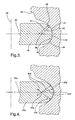
- Figure 3 is a partial cross-sectional view of the engagement between a roller and a guide groove of the first exemplary embodiment of the invention;
- Figure 4 is a partial cross-sectional view of the engagement between a roller and a guide groove of a second exemplary embodiment of the invention;
- Figure 5 is a partial cross-sectional view of the engagement between a roller and a guide groove of a third exemplary embodiment of the invention; and
- Figure 6 is a partial cross-sectional view of the engagement between a roller and a guide groove of a fourth exemplary embodiment of the invention.
- A plurality of different embodiments of the invention are shown in the Figures of the application. Similar features are shown in the various embodiments of the invention. Similar features have been numbered with a common reference numeral and have been differentiated by an alphabetic designation. Also, to enhance consistency, features in any particular drawing share the same alphabetic designation even if the feature is shown in less than all embodiments. Similar features are structured similarly, operate similarly, and/or have the same function unless otherwise indicated by the drawings or this specification. Furthermore, particular features of one embodiment can replace corresponding features in another embodiment unless otherwise indicated by the drawings or this specification.
- Referring now to Figures 1 and 2, a tripot
universal joint 10 includes a housing orouter drive member 12, aninner drive member 14 and three drive roller orsemi-spherical ball assemblies 16. Theouter drive member 12 has alongitudinal axis 18 about which it rotates and threeradial guide grooves 20 which are equally spaced at substantially 120 degrees from each other and parallel to theaxis 18. Each of theguide grooves 20 has two opposingconcave side portions longitudinal back surface 26 which faces radially inward. Theinner drive member 14 has ashaft 28 and alongitudinal axis 30 about which theshaft 28 rotates. Thelongitudinal axis universal joint 10 is at zero angle, as shown in FIG. 1, and intersects at a point on thelongitudinal axis 18 when the tripotuniversal joint 10 is articulated or bent at an angle as shown in FIG. 2. Theaxis longitudinal axis 18 which is spaced from ajoint center 32. - The
inner drive member 14 has threeradial arms 34 equally spaced at 120 degrees from each other about theaxis 30 on co-planarradial axis 36 which intersect thelongitudinal axis 30 perpendicularly at a spider center 38. The spider center 38 lies on thelongitudinal axis 18 of theouter drive member 12 at zero angle and is displaced radially from thelongitudinal axis 18 and orbits around thejoint center 32 at three times the joint speed when the tripotuniversal joint 10 is articulated and rotated at a given speed. Each of thearms 34 extend into one of theguide grooves 20 of the outerjoint member 12. - Each one of the
radial arms 34 carries aroller 40 of the ball assembly for engaging thecorresponding guide groove 20. In one exemplary embodiment of the invention, eacharm 34 can have a convex or semi-spherical surface which is concentric to theradial axis 36. Theball assemblies 16 can be mounted on theradial arms 34 both rotatably and pivotally. Disposed directly radially outward from the semi-spherical surface of thearms 34 could be an annular inner roller or ball which has an inner radial concave mating surface which conforms to the semi-spherical surface of thearms 34 so that theball assembly 16 can tilt or pivot with respect to theradial axis 36. Theroller 40 can be radially outwardly disposed relative to the inner roller and rotate with respect to the inner ball via a train of needle bearings or rollers disposed directly radially between theouter roller 40 and the inner ball. Such an arrangement is shown inU.S. Pat. No. 6,758,758 , which is hereby incorporated by reference. - The
roller 40 a roller has anexternal surface 42 which engages theopposed side portions guide groove 20 into which thearm 34 extends so that theroller 40 is constrained to roll therealong. Eachroller 40 is able to rotate about, move lengthwise of, and tilt relative to thearm 34 by which it is carried. - The cross-sectional shape of said
external surface 42 of eachroller 40 is at least partially of arcuate shape. Aradius 54 of the arcuate shape of theexternal surface 42 extends from apoint 56 that is at least as close to the rollerexternal surface 42 as aplane 50 that is centered with respect to theroller 40 along a path extending normal to theexternal surface 42. In other words, the radius extends from theplane 50 or extends from a point between theplane 50 and theexternal surface 42 along an axis normal to the external surface. In other words, the arcuate shape is not part of a Gothic arch. - In the first exemplary embodiment, the cross-sectional shape of the
external surface 42 of eachroller 40 is of a truncated arcuate shape. Specifically, the firstexemplary surface 42 has a truncated semi-circle shape. For example, thesurface 42 includes first andsecond arc portions same point 56. Thepoint 56 is as close to the rollerexternal surface 42 as theplane 50 along a path extending normal to the external surface 42 (theradius 54 is normal to the external surface 42). - The
surface 42 also includes atruncated portion 48 extending between the first andsecond arc portions truncated portion 48 is shown as being straight in Figure 3, but could be slightly arcuate and/or blended between the first andsecond arc portions side portion 22. Thesurface 42 engages theside portion 22 tangentially. - As set forth above, the cross-sectional shape of each guide
groove side portion groove side portion groove side portion external surface 42. As best seen in Figure 3, theradius 52 of theside portion 22 is greater than theradius 54 of thearcuate portions surface 42. As a result, the rollerexternal surface 42 and each guidegroove side portion external surface 42 and guidegroove side portion 22. - As shown in Figure 4, in a second embodiment of the invention, two
radii 52a of thegroove side portion 22a cooperate to form a Gothic arch. Theexternal surface 42a of theroller 40a is defined by theradius 54a extending from thepoint 56a. Thepoint 56a is on theplane 50a. Theexternal surface 42a of theroller 40a is of a semi-circular arcuate shape and is spaced from thegroove portion 22a. - As shown in Figure 5, in a third embodiment of the invention, the
radius 52b of thegroove side portion 22b defines a semi-circular shape. Theexternal surface 42b of theroller 40b is defined by tworadii 54b defining first and secondarcuate portions 44b, 46b. Atruncated portion 48b extends between the first and secondarcuate portions 44b, 46b. Eachradius 54b is closer to the correspondingarcuate portion 44b, 46b than theplane 50b along respective paths normal to the respectivearcuate portions 44b, 46b. Therespective origins radii 54b are offset from one another, mirrored from one another relative to theplane 50b. - As shown in Figure 6, in a fourth embodiment of the invention, two
radii 52c of thegroove side portion 22c cooperate to form a Gothic arch. Theexternal surface 42c of theroller 40c is defined by tworadii 54c defining first and secondarcuate portions 44c, 46c. Atruncated portion 48c extends between the first and secondarcuate portions 44c, 46c. Eachradii 54c is closer to the correspondingarcuate portion 44c, 46c than theplane 50c along respective paths normal to the respectivearcuate portion 44c, 46c. Therespective origins 56c, 58c of the tworadii 54c are offset from one another, mirrored from one another relative to theplane 50c. - While the invention has been described with reference to an exemplary embodiment, it will be understood by those skilled in the art that various changes may be made and equivalents may be substituted for elements thereof without departing from the scope of the invention. In addition, many modifications may be made to adapt a particular situation or material to the teachings of the invention without departing from the essential scope thereof. Therefore, it is intended that the invention not be limited to the particular embodiment disclosed as the best mode contemplated for carrying out this invention, but that the invention will include all embodiments falling within the scope of the appended claims.
Claims (9)
- A constant velocity ratio universal joint (10) of the tripot type comprising an outer joint member (12) having a rotational axis (18) and three guide grooves (20) extending parallel to its rotational axis (18) and equally circumferentially spaced thereabout, each guide groove (20) having opposed side portions (22, 24); and inner joint member (14) disposed inside the outer member (12), having a rotational axis (30) and three arms (34) equally spaced about this rotational axis (30) and extending radially into the guide grooves (22, 24) of the outer joint member (12); each arm (34) carrying a roller (40) having an external surface (42) which engages said opposed side portions (22, 24) of the guide groove (20) into which the arm (34) extends so that the roller (40) is constrained to roll therealong; each roller (40) being able to rotate about, move lengthwise of, and tilt relative to the arm (34) by which it is carried; wherein the cross-sectional shape of said external surface (42) of each roller (40) is of an arcuate shape, and the cross-sectional shape of each guide groove side portion (22, 24) is different from said arcuate shape of the roller external surface (42), said roller external surface (42) and each guide groove side portion (22, 24) having angular contact engagement with one another at two spaced points which lie in said roller external surface (42) and guide groove side portion (22, 24), wherein a radius (54) of said arcuate shape of said external surface (42) extends from a point (56) at least as close to said roller external surface (42) as a plane (50) centered with respect to said roller (40) along a path extending normal to said external surface (42).
- The constant velocity ratio universal joint (10) of claim 1 wherein:said roller external surface (42) is of truncated arcuate shape with first and second arc portions (44, 46) and a truncated portion (48) disposed between said first and second arc portions (44, 46).
- The constant velocity ratio universal joint (10) of claim 2 wherein said first and second arc portions (44, 46) are centered on the same point 56.
- The constant velocity ratio universal joint (10) of claim 2 wherein:said cross-sectional shape of each guide groove side portion (22, 24) is of semi-circular shape.
- The constant velocity ratio universal joint (10) of claim 1 wherein:said roller external surface (42a) is of semi-circular arcuate shape.
- The constant velocity ratio universal joint (10) of claim 5 wherein:said cross-sectional shape of each guide groove side portion (22a) is of Gothic arch shape.
- The constant velocity ratio universal joint (10) of claim 1 wherein:said roller external surface (42b, 42c) is of truncated arcuate shape with first and second arc portions (44b, 44c, 46b, 46c) centered on different points (56b, 56c, 58b, 58c) and a truncated portion (48b, 48c) disposed between said first and second arc portions (44b, 44c, 46b, 46c).
- The constant velocity ratio universal joint (10) of claim 7 wherein:said cross-sectional shape of each guide groove side portion (22b) is of semi-circular shape.
- The constant velocity ratio universal joint (10) of claim 7 wherein:said cross-sectional shape of each guide groove side portion (22c) is of Gothic arch shape.
Applications Claiming Priority (1)
| Application Number | Priority Date | Filing Date | Title |
|---|---|---|---|
| US11/257,557 US7435181B2 (en) | 2005-10-25 | 2005-10-25 | Tripot ball with two point contact |
Publications (3)
| Publication Number | Publication Date |
|---|---|
| EP1780431A2 true EP1780431A2 (en) | 2007-05-02 |
| EP1780431A3 EP1780431A3 (en) | 2009-12-02 |
| EP1780431B1 EP1780431B1 (en) | 2013-02-27 |
Family
ID=37607382
Family Applications (1)
| Application Number | Title | Priority Date | Filing Date |
|---|---|---|---|
| EP06076865A Expired - Fee Related EP1780431B1 (en) | 2005-10-25 | 2006-10-11 | Tripot joint roller with two point contact |
Country Status (2)
| Country | Link |
|---|---|
| US (1) | US7435181B2 (en) |
| EP (1) | EP1780431B1 (en) |
Cited By (1)
| Publication number | Priority date | Publication date | Assignee | Title |
|---|---|---|---|---|
| WO2021098945A1 (en) * | 2019-11-18 | 2021-05-27 | Gkn Driveline International Gmbh | Tripod type constant velocity joint |
Families Citing this family (5)
| Publication number | Priority date | Publication date | Assignee | Title |
|---|---|---|---|---|
| US8177649B2 (en) * | 2008-06-13 | 2012-05-15 | Hyundai Wia Corporation | Constant velocity joint of tripod type |
| JP4940314B2 (en) * | 2010-01-15 | 2012-05-30 | 株式会社タカラトミー | Car toy |
| JP4875758B2 (en) * | 2010-01-15 | 2012-02-15 | 株式会社タカラトミー | Joint structure for toys |
| JP2011143088A (en) * | 2010-01-15 | 2011-07-28 | Tomy Co Ltd | Automobile toy |
| US20150198206A1 (en) * | 2013-11-13 | 2015-07-16 | Nexteer (Beijing) Technology Co., Ltd. | Torque-transmitting joint and joint components, methods of manufacturing, and methods of inspection |
Citations (4)
| Publication number | Priority date | Publication date | Assignee | Title |
|---|---|---|---|---|
| GB2252144A (en) | 1991-01-24 | 1992-07-29 | Sobhy Labib Girguis | Constant velocity universal joint |
| US5203741A (en) | 1988-11-26 | 1993-04-20 | Hardy Spicer Limited | Constant velocity ratio universal joint with gothic arch shaped rollers and guide grooves |
| FR2785342A1 (en) | 1998-11-02 | 2000-05-05 | Ntn Toyo Bearing Co Ltd | Homo-kinetic joint for motor vehicle transmission contact point between inner and outer rollers positioned to generate set force angles |
| EP1503097A2 (en) | 2003-07-31 | 2005-02-02 | Ntn Corporation | Tripod type constant velocity joint |
Family Cites Families (37)
| Publication number | Priority date | Publication date | Assignee | Title |
|---|---|---|---|---|
| FR2474120A1 (en) | 1979-12-20 | 1981-07-24 | Citroen Sa | IMPROVEMENTS ON UNIVERSAL JOINTS |
| FR2499645B1 (en) | 1981-02-09 | 1986-05-30 | Glaenzer Spicer Sa | TRIPOD HOMOCINETIC JOINT, ITS ASSEMBLY METHOD AND ITS APPLICATION IN A WHEEL HUB |
| FR2506874B1 (en) | 1981-06-01 | 1986-08-29 | Glaenzer Spicer Sa | HOMOCINETIC JOINT WITH TRIPOD WITH ROTATING ROLLERS |
| US4674993A (en) | 1985-02-28 | 1987-06-23 | The Zeller Corporation | Tripot universal joint of the end motion type |
| US4589856A (en) | 1985-02-28 | 1986-05-20 | The Zeller Corporation | Tripot universal joint of the end motion type |
| JPH0322577Y2 (en) | 1985-09-17 | 1991-05-16 | ||
| JPS62233522A (en) * | 1986-04-02 | 1987-10-13 | Ntn Toyo Bearing Co Ltd | Equal velocity universal joint |
| GB2195167B (en) | 1986-09-17 | 1990-03-21 | Ntn Toyo Bearing Co Ltd | Homokinetic universal joint |
| US4810232A (en) | 1987-01-28 | 1989-03-07 | General Motors Corporation | Telescopic tripot universal joint |
| FR2621660B1 (en) | 1987-10-09 | 1994-03-11 | Glaenzer Spicer | LOAD TRANSFER DEVICE USING A SMOOTH TURNED BEARING ELEMENT, METHODS OF MAKING SAME, AND TRANSMISSION JOINT THEREOF |
| GB8829530D0 (en) * | 1988-12-17 | 1989-02-01 | Spicer Hardy Ltd | Constant velocity ratio universal joints |
| DE4130183C2 (en) | 1991-09-11 | 1994-01-20 | Gkn Automotive Ag | Tripod joint |
| DE4130963C2 (en) | 1991-09-18 | 1995-07-27 | Loehr & Bromkamp Gmbh | Tripod joint |
| FR2688848B1 (en) | 1992-03-18 | 1994-06-17 | Gkn Automotive Ag | SLIDING TYPE ARTICULATED TRANSMISSION JOINT. |
| GB2268789B (en) | 1992-07-14 | 1995-05-17 | Loehr & Bromkamp Gmbh | Tripode type constant velocity ratio joints |
| USRE36163E (en) | 1992-09-10 | 1999-03-23 | Lohr & Bromkamp Gmbh | Tripod joint |
| ES2088759B1 (en) | 1992-12-08 | 1998-08-01 | Gkn Automotive Ag | SYNCHRONOUS SWIVEL JOINT |
| DE4305278C1 (en) | 1993-02-20 | 1994-07-28 | Gkn Automotive Ag | Tripod type constant velocity universal joint |
| DE4429479C2 (en) | 1994-08-19 | 1997-02-20 | Loehr & Bromkamp Gmbh | Tripod joint with roller lock |
| GB9513575D0 (en) | 1995-07-04 | 1995-09-06 | Gkn Technology Ltd | Tripode type constant velocity ratio universal joints |
| US6217454B1 (en) | 1996-01-12 | 2001-04-17 | Nsk Ltd. | Tripod type constant velocity joint |
| US6837794B1 (en) | 1996-02-05 | 2005-01-04 | Ntn Corporation | Tripod type constant velocity universal joint |
| EP1008777B1 (en) | 1996-02-05 | 2007-04-25 | Ntn Corporation | Tripod type constant velocity universal joint |
| JP3043280B2 (en) | 1996-02-15 | 2000-05-22 | 本田技研工業株式会社 | Constant velocity joint |
| JP3690074B2 (en) | 1997-06-27 | 2005-08-31 | 日本精工株式会社 | Tripod type constant velocity joint |
| JP2000039028A (en) * | 1998-07-22 | 2000-02-08 | Ntn Corp | Slide type constant velocity joint |
| DE19834513A1 (en) | 1998-07-31 | 2000-02-03 | Schaeffler Waelzlager Ohg | Tripod constant velocity swivel |
| JP2000240675A (en) | 1998-12-22 | 2000-09-05 | Ntn Corp | Tripod type constant velocity universal joint |
| FR2790050B1 (en) | 1999-02-24 | 2002-06-07 | Gkn Glaenzer Spicer | HOMOCINETIC TRANSMISSION JOINT AND MECHANICAL TRANSMISSION MEMBER FOR SUCH A JOINT |
| US6632143B2 (en) | 2000-03-31 | 2003-10-14 | Ntn Corporation | Constant velocity universal joint |
| FR2819863B1 (en) | 2001-01-23 | 2003-06-13 | Gkn Glaenzer Spicer | HOMOCINETIC TRANSMISSION JOINT AND MECHANICAL TRANSMISSION MEMBER FOR SUCH A JOINT |
| US6699134B2 (en) | 2001-02-21 | 2004-03-02 | Visteon Global Technologies, Inc. | Anti-shudder tripod type CV universal joint |
| JP4015822B2 (en) | 2001-04-25 | 2007-11-28 | Ntn株式会社 | Constant velocity universal joint |
| US6669134B2 (en) * | 2001-10-03 | 2003-12-30 | Delphi Technologies, Inc. | Take up guide tensioning system |
| DE10161987C2 (en) | 2001-12-17 | 2003-11-13 | Gkn Automotive Gmbh | Tripodegelenkanordnung |
| US6758758B2 (en) | 2002-06-14 | 2004-07-06 | Delphi Technologies, Inc. | Tripot universal joint |
| US6776719B2 (en) | 2002-06-14 | 2004-08-17 | Delphi Technologies, Inc. | Tripot universal joint |
-
2005
- 2005-10-25 US US11/257,557 patent/US7435181B2/en active Active
-
2006
- 2006-10-11 EP EP06076865A patent/EP1780431B1/en not_active Expired - Fee Related
Patent Citations (4)
| Publication number | Priority date | Publication date | Assignee | Title |
|---|---|---|---|---|
| US5203741A (en) | 1988-11-26 | 1993-04-20 | Hardy Spicer Limited | Constant velocity ratio universal joint with gothic arch shaped rollers and guide grooves |
| GB2252144A (en) | 1991-01-24 | 1992-07-29 | Sobhy Labib Girguis | Constant velocity universal joint |
| FR2785342A1 (en) | 1998-11-02 | 2000-05-05 | Ntn Toyo Bearing Co Ltd | Homo-kinetic joint for motor vehicle transmission contact point between inner and outer rollers positioned to generate set force angles |
| EP1503097A2 (en) | 2003-07-31 | 2005-02-02 | Ntn Corporation | Tripod type constant velocity joint |
Cited By (1)
| Publication number | Priority date | Publication date | Assignee | Title |
|---|---|---|---|---|
| WO2021098945A1 (en) * | 2019-11-18 | 2021-05-27 | Gkn Driveline International Gmbh | Tripod type constant velocity joint |
Also Published As
| Publication number | Publication date |
|---|---|
| US20070093301A1 (en) | 2007-04-26 |
| EP1780431B1 (en) | 2013-02-27 |
| EP1780431A3 (en) | 2009-12-02 |
| US7435181B2 (en) | 2008-10-14 |
Similar Documents
| Publication | Publication Date | Title |
|---|---|---|
| US7316620B2 (en) | Constant velocity universal joint | |
| EP1707834B1 (en) | Tripod type constant verocity universal joint | |
| JP4541203B2 (en) | Tripod type constant velocity universal joint | |
| EP1780431B1 (en) | Tripot joint roller with two point contact | |
| KR100614001B1 (en) | Tripod constant velocity joint structure | |
| EP1327083B1 (en) | Constant velocity joint of tripod type | |
| US6893351B2 (en) | Tripod type constant velocity universal joint | |
| US20130097867A1 (en) | Constant velocity joint and method of making | |
| JP2001295855A (en) | Uniform universal coupling | |
| US6776719B2 (en) | Tripot universal joint | |
| US6758758B2 (en) | Tripot universal joint | |
| JPH0747971B2 (en) | Tripot type constant velocity joint | |
| US20110086714A1 (en) | Constant velocity joint | |
| EP0279127A1 (en) | Telescopic tripot universal joint | |
| JP4350392B2 (en) | Tripod type constant velocity universal joint | |
| EP2216560A1 (en) | Tripod-type constant velocity joint | |
| CN111379795A (en) | Constant velocity joint | |
| JP2583634Y2 (en) | Automotive tripod type constant velocity joint | |
| US7097565B2 (en) | Fixed-center articulating constant velocity joint | |
| JP2000291677A (en) | Tripod constant velocity universal joint | |
| JP2001280358A (en) | Constant velocity universal joint | |
| CN113446325A (en) | Constant velocity joint | |
| JPH1113782A (en) | Double cardan type constant velocity joint | |
| JP2006266325A (en) | Constant velocity universal joint | |
| JP2000291676A (en) | Tripod constant velocity universal joint |
Legal Events
| Date | Code | Title | Description |
|---|---|---|---|
| PUAI | Public reference made under article 153(3) epc to a published international application that has entered the european phase |
Free format text: ORIGINAL CODE: 0009012 |
|
| AK | Designated contracting states |
Kind code of ref document: A2 Designated state(s): AT BE BG CH CY CZ DE DK EE ES FI FR GB GR HU IE IS IT LI LT LU LV MC NL PL PT RO SE SI SK TR |
|
| AX | Request for extension of the european patent |
Extension state: AL BA HR MK YU |
|
| PUAL | Search report despatched |
Free format text: ORIGINAL CODE: 0009013 |
|
| AK | Designated contracting states |
Kind code of ref document: A3 Designated state(s): AT BE BG CH CY CZ DE DK EE ES FI FR GB GR HU IE IS IT LI LT LU LV MC NL PL PT RO SE SI SK TR |
|
| AX | Request for extension of the european patent |
Extension state: AL BA HR MK RS |
|
| 17P | Request for examination filed |
Effective date: 20100224 |
|
| 17Q | First examination report despatched |
Effective date: 20100324 |
|
| AKX | Designation fees paid |
Designated state(s): DE |
|
| RAP1 | Party data changed (applicant data changed or rights of an application transferred) |
Owner name: GM GLOBAL TECHNOLOGY OPERATIONS, INC. |
|
| RAP1 | Party data changed (applicant data changed or rights of an application transferred) |
Owner name: GM GLOBAL TECHNOLOGY OPERATIONS LLC |
|
| GRAP | Despatch of communication of intention to grant a patent |
Free format text: ORIGINAL CODE: EPIDOSNIGR1 |
|
| RAP1 | Party data changed (applicant data changed or rights of an application transferred) |
Owner name: GM GLOBAL TECHNOLOGY OPERATIONS LLC Owner name: STEERING SOLUTIONS IP HOLDING CORPORATION |
|
| GRAS | Grant fee paid |
Free format text: ORIGINAL CODE: EPIDOSNIGR3 |
|
| GRAA | (expected) grant |
Free format text: ORIGINAL CODE: 0009210 |
|
| AK | Designated contracting states |
Kind code of ref document: B1 Designated state(s): DE |
|
| REG | Reference to a national code |
Ref country code: DE Ref legal event code: R082 Ref document number: 602006034708 Country of ref document: DE Representative=s name: MANITZ, FINSTERWALD & PARTNER GBR, DE Ref country code: DE Ref legal event code: R082 Ref document number: 602006034708 Country of ref document: DE Representative=s name: MANITZ FINSTERWALD PATENTANWAELTE PARTMBB, DE |
|
| REG | Reference to a national code |
Ref country code: DE Ref legal event code: R096 Ref document number: 602006034708 Country of ref document: DE Effective date: 20130425 |
|
| PLBE | No opposition filed within time limit |
Free format text: ORIGINAL CODE: 0009261 |
|
| STAA | Information on the status of an ep patent application or granted ep patent |
Free format text: STATUS: NO OPPOSITION FILED WITHIN TIME LIMIT |
|
| 26N | No opposition filed |
Effective date: 20131128 |
|
| REG | Reference to a national code |
Ref country code: DE Ref legal event code: R097 Ref document number: 602006034708 Country of ref document: DE Effective date: 20131128 |
|
| PGFP | Annual fee paid to national office [announced via postgrant information from national office to epo] |
Ref country code: DE Payment date: 20161027 Year of fee payment: 11 |
|
| REG | Reference to a national code |
Ref country code: DE Ref legal event code: R119 Ref document number: 602006034708 Country of ref document: DE |
|
| PG25 | Lapsed in a contracting state [announced via postgrant information from national office to epo] |
Ref country code: DE Free format text: LAPSE BECAUSE OF NON-PAYMENT OF DUE FEES Effective date: 20180501 |