EP1780111B1 - Bicycle bottom bracket assembly - Google Patents
Bicycle bottom bracket assembly Download PDFInfo
- Publication number
- EP1780111B1 EP1780111B1 EP06022160A EP06022160A EP1780111B1 EP 1780111 B1 EP1780111 B1 EP 1780111B1 EP 06022160 A EP06022160 A EP 06022160A EP 06022160 A EP06022160 A EP 06022160A EP 1780111 B1 EP1780111 B1 EP 1780111B1
- Authority
- EP
- European Patent Office
- Prior art keywords
- bearings
- bottom bracket
- bracket assembly
- bearing support
- support members
- Prior art date
- Legal status (The legal status is an assumption and is not a legal conclusion. Google has not performed a legal analysis and makes no representation as to the accuracy of the status listed.)
- Active
Links
- 239000007769 metal material Substances 0.000 claims description 7
- 230000000717 retained effect Effects 0.000 claims description 4
- 239000011347 resin Substances 0.000 description 10
- 229920005989 resin Polymers 0.000 description 10
- 239000000463 material Substances 0.000 description 6
- 230000004323 axial length Effects 0.000 description 3
- 230000036961 partial effect Effects 0.000 description 3
- XAGFODPZIPBFFR-UHFFFAOYSA-N aluminium Chemical compound [Al] XAGFODPZIPBFFR-UHFFFAOYSA-N 0.000 description 2
- 229910052782 aluminium Inorganic materials 0.000 description 2
- 230000000670 limiting effect Effects 0.000 description 2
- VYZAMTAEIAYCRO-UHFFFAOYSA-N Chromium Chemical compound [Cr] VYZAMTAEIAYCRO-UHFFFAOYSA-N 0.000 description 1
- ZOKXTWBITQBERF-UHFFFAOYSA-N Molybdenum Chemical compound [Mo] ZOKXTWBITQBERF-UHFFFAOYSA-N 0.000 description 1
- 229910000831 Steel Inorganic materials 0.000 description 1
- 239000000956 alloy Substances 0.000 description 1
- 229910045601 alloy Inorganic materials 0.000 description 1
- 230000002860 competitive effect Effects 0.000 description 1
- 230000009977 dual effect Effects 0.000 description 1
- 239000004519 grease Substances 0.000 description 1
- 239000011499 joint compound Substances 0.000 description 1
- 238000005461 lubrication Methods 0.000 description 1
- 238000012423 maintenance Methods 0.000 description 1
- 238000000034 method Methods 0.000 description 1
- 238000012986 modification Methods 0.000 description 1
- 230000004048 modification Effects 0.000 description 1
- 229910052750 molybdenum Inorganic materials 0.000 description 1
- 239000011733 molybdenum Substances 0.000 description 1
- 230000000149 penetrating effect Effects 0.000 description 1
- 238000003825 pressing Methods 0.000 description 1
- 230000002829 reductive effect Effects 0.000 description 1
- 238000005096 rolling process Methods 0.000 description 1
- 239000004576 sand Substances 0.000 description 1
- 239000010959 steel Substances 0.000 description 1
- XLYOFNOQVPJJNP-UHFFFAOYSA-N water Substances O XLYOFNOQVPJJNP-UHFFFAOYSA-N 0.000 description 1
- 238000003466 welding Methods 0.000 description 1
Images


Classifications
-
- B—PERFORMING OPERATIONS; TRANSPORTING
- B62—LAND VEHICLES FOR TRAVELLING OTHERWISE THAN ON RAILS
- B62M—RIDER PROPULSION OF WHEELED VEHICLES OR SLEDGES; POWERED PROPULSION OF SLEDGES OR SINGLE-TRACK CYCLES; TRANSMISSIONS SPECIALLY ADAPTED FOR SUCH VEHICLES
- B62M3/00—Construction of cranks operated by hand or foot
- B62M3/003—Combination of crank axles and bearings housed in the bottom bracket
-
- Y—GENERAL TAGGING OF NEW TECHNOLOGICAL DEVELOPMENTS; GENERAL TAGGING OF CROSS-SECTIONAL TECHNOLOGIES SPANNING OVER SEVERAL SECTIONS OF THE IPC; TECHNICAL SUBJECTS COVERED BY FORMER USPC CROSS-REFERENCE ART COLLECTIONS [XRACs] AND DIGESTS
- Y10—TECHNICAL SUBJECTS COVERED BY FORMER USPC
- Y10T—TECHNICAL SUBJECTS COVERED BY FORMER US CLASSIFICATION
- Y10T74/00—Machine element or mechanism
- Y10T74/21—Elements
- Y10T74/2164—Cranks and pedals
Description
- This invention generally relates to a bicycle bottom bracket assembly. More specifically, the present invention relates to a bicycle bottom bracket assembly having bearings located within a cylindrical hanger part or bottom bracket tube of the bicycle frame. Background Information
- Bicycling is becoming an increasingly more popular form of recreation as well as a means of transportation. Moreover, bicycling has become a very popular competitive sport for both amateurs and professionals. Whether the bicycle is used for recreation, transportation or competition, the bicycle industry is constantly improving the various components of the bicycle. One component that has been extensively redesigned is the bicycle bottom bracket that is often called a bottom bracket.
- Japanese Laid-Open Patent Publication No.
2004-249770 - In such conventional bottom bracket, the right gear crank is secured on the right axial end portion of the crank axle. The inner rings of the first and second bearings are pressed by inner edge parts of the right and left cranks and disposed so that the right and left cranks can exert pressure to the inner rings of the first and second bearings. The left crank is non-rotatably mounted on the crank axle by a serration that is formed on a circumference surface at the left axial end portion of the crank axle. Moreover, the left crank is fastened to the crank axle by a fastening bolt that is screwed on the left edge inner circumference surface of the crank axle. When the left crank is fastened to the crank axle by the fastening bolt, the right and left cranks press the inner rings of the first and second bearings inwardly in the axial direction by placing the right and left cranks in contact with the outside surfaces of the inner rings of the first and second bearings in the axial direction. In addition, a slit is formed along the radial direction on a crank axle mounting part of the left crank. After fastening the left crank by the fastening bolt, the left crank can be further tightened securely on the crank axle by narrowing the width of the slit by using two mounting bolts. In the conventional bicycle bottom bracket as explained above, by pressing the inner rings of the first and second bearings by using the fastening bolt that secures the left crank, the bearing play is adjusted through the left crank by fastening the left crank to the crank axle. Then, the left crank is further secured onto the crank axle by narrowing the width of the slit of the left crank by the mounting bolts.
- However, in this type of conventional bicycle bottom bracket, the bearings are located outside of the cylindrical hanger part or bottom bracket tube of the bicycle frame. As a result, the axial length of the bottom bracket tube of the bicycle frame needs to be made small enough to accommodate the bearings being located outside of the bottom bracket tube of the bicycle frame. Moreover, since the first and second axle support housings are screwed into the bottom bracket tube of the bicycle frame, the first and second axle support housings are made of a metallic material and the ends of the bottom bracket tube are threaded. Thus, this conventional bicycle bottom bracket structure can be heavy and requires threading of the ends of the bottom bracket tube.
- A further conventional bearing receiving and supporting assembly for a bicycle pedal crank axle is known from German utility model No.
DE 85 18 158 U1 . This document discloses a bearing receiving and supporting assembly for a bicycle pedal crank axle within a tube-shaped hanger part of the bicycle frame. The bearings are grooved ball bearings with an outer annular ring and an inner annular ring. The inner annular ring is press-fitted to the outer surface of the pedal crank axle. The outer annular ring is received by the inner surfaces of a bushing that comprises a flange. The bearings are further supported in axial direction via radially inwardly directed projections at the inner ends of the bushing. The flange serves also for a support of the bushing in an axial direction through contacting the outer circumferential side surfaces of the tube-shaped hanger part.
Document 454552468 discloses a bicycle bottom bracket assembly according to the preamble of claim 1. - In view of the above, it will be apparent to those skilled in the art from this disclosure that there exists a need for an improved bicycle crank axle bearing assembly or bottom bracket. This invention addresses this need in the art as well as other needs, which will become apparent to those skilled in the art from this disclosure.
- One object of the present invention is to provide a bicycle bottom bracket assembly having bearings that are retained in non-metallic bearing support members or housings within the ends of a hanger part of a bicycle frame.
- Another object of the present invention is to provide a bicycle bottom bracket assembly that is relatively lightweight.
- Another object of the present invention is to provide a bicycle bottom bracket assembly that does not require the ends of the hanger part of the bicycle frame to be threaded.
- The forgoing objects can basically be attained by providing a bicycle bottom bracket assembly that includes first and second bearing support members (housings) with each of the first and second bearing support members having an external abutment part adjacent a non-threaded outer circumferential surface, and first and second bearings so that the bottom bracket assembly is configured and arranged to be mounted into a hanger part of a bicycle frame. The hanger part of a bicycle frame has a first open end and a second open end. The first and second bearing support members are press-fitted into the first and second open ends of the hanger part, respectively via the outer circumferential surfaces of the external abutment parts. The first and second bearings are retained in the first and second bearing support members, respectively, such that the first and second bearings are disposed inside of the hanger part, i.e. axially inwardly of the external abutment part of a corresponding one of the first and second bearing support members with outer races of each of the first and second bearings engaging the first and second bearing support members, respectively. A crank axle is rotatably supported within the hanger part by inner races of the first and second bearings with a first axial end portion of the crank axle being disposed at the first open end of the hanger part and a second axial end portion of the crank axle being disposed at the second open end of the hanger part. Further, first and second first and second cover members are disposed radially inwardly from the inner races of the first and second bearings, respectively. The first and second cover members are configured and arranged so that a crank axle is removable from the first and second cover members in an axial direction without removing the first and second cover members from the inner races of the first and second bearings, and/or without removing the first and second cover members from the hanger part.
- In accordance with one aspect of the present invention, the bottom bracket assembly is characterized in that the bearing housing is press-fitted into the cylindrical hanger part so that the bearings are axially positioned inwardly from or flush with the axial ends of the cylindrical hanger part.
- In accordance with another aspect of the present invention, the bottom bracket assembly is characterized in that the bearing support members (housings) are made of a non-metallic material (e.g., resin) and are coupled into the cylindrical hanger part in a manner of press-fitting. Thus, such a structure allows the axial length of the cylindrical hanger part to be longer in comparison with the length of the conventional design discussed above, and increases design freedom of parts attached to this area of the bicycle frame. Further, since the bottom bracket assembly of the invention comprises a bearing sandwiched between the bearing housing and the cover member, a user can easily couple the bottom bracket as a unit into the cylindrical hanger part in a press-fitting manner. Preferably, the bearing housing may be made of resin. Such a bearing housing made of resin results in weight-saving and reducing noise during pedaling.
- These and other objects, features, aspects and advantages of the present invention will become apparent to those skilled in the art from the following detailed description, which, taken in conjunction with the annexed drawings, discloses a preferred embodiment of the present invention.
- Referring now to the attached drawings which form a part of this original disclosure:
-
Figure 1 is an overall right side elevational view of a bicycle with a bicycle bottom bracket assembly in accordance with a first embodiment of the present invention; -
Figure 2 is an enlarged, partial perspective view of a hanger part of the bicycle frame of the bicycle illustratedFigure 1 with the bottom bracket installed in the hanger part in accordance with the first embodiment of the present invention; -
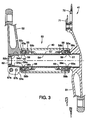
Figure 3 is a transverse cross sectional view of the bottom bracket assembly in accordance with the first embodiment of the present invention; -
Figure 4 is an enlarged partial cross sectional view of a left side portion of the bottom bracket assembly in accordance with the first embodiment of the present invention; -
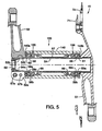
Figure 5 is a transverse cross sectional view of the bottom bracket assembly in accordance with a second embodiment of the present invention; and -
Figure 6 is an enlarged partial cross sectional view of a left side portion of the bottom bracket assembly in accordance with the second embodiment of the present invention. - Selected embodiments of the present invention will now be explained with reference to the drawings. It will be apparent to those skilled in the art from this disclosure that the following descriptions of the embodiments of the present invention are provided for illustration only and not for the purpose of limiting the invention as defined by the appended claims.
- Referring initially to
Figure 1 , abicycle 10 is illustrated that is equipped a first embodiment of the present invention. In this example, thebicycle 10 is a road bike that has a diamond-shapedframe 12 with a triangularly shaped front triangle and a triangularly shaped rear triangle that is arranged rearward of the front triangle. Theframe 12 serves as the framework of the bicycle body. Theframe 12 has afront fork 14 pivotally supported on a front part of theframe 12 such that thefront fork 14 can rotate freely about an axis that is tilted slightly from vertical. The lower or bottom part of thefront fork 14 is divided into two prongs. Thebicycle 10 is also provided with a drop-type handlebar unit 16 connected to thefront fork 14, and adrive unit 18 provided on a lower part of theframe 12. Thedrive unit 18 is configured to convert pedaling force into driving force. Afront wheel 20 is supported in a freely rotatable manner on the bottom end of thefront fork 14, while arear wheel 22 is supported in a freely rotatable manner on a rear part of theframe 12. Of course, thebicycle 10 can include other components as needed and/or desired. - The
frame 12 is basically formed by atop tube 24, adown tube 26, ahead tube 28, aseat tube 30, a pair of seat stays 32 and a pair of chain stays 34. Thetop tube 24 is arranged generally horizontally, while thedown tube 26 is arranged below thetop tube 24 such that it slants obliquely upward toward the front. Thehead tube 28 joins the front ends of thetop tube 24 and thedown tube 26 together. Theseat tube 30 extends diagonally upward and joins the rear ends of thetop tube 24 and thedown tube 26 together. - The
bicycle 10 is also provided with aseat post 36 has asaddle 38 fastened thereto. Theseat post 36 is secured in theseat tube 30 such that its position can be vertically adjusted up and down. A cylindrical or tubular hanger part 40 (shown inFigure 2 ) is formed at a connection portion where theseat tube 30 and thedown tube 26 are joined together. - The
drive unit 18 basically includes afront crankset 41, a reargear cassette unit 43, achain 44, afront derailleur 45, and arear derailleur 46. Thefront crankset 41 is provided on the bottom bracket of thebicycle 10. The reargear cassette unit 43 is mounted in a non-rotatable manner to the free hub of therear wheel 22. Thechain 44 is arranged on thefront crankset 41 and the reargear cassette unit 43 so as to span therebetween. Thefront derailleur 45 and therear derailleur 46 function as gear changing devices. - As shown in
Figures 2 and3 , thefront crankset 41 basically includes a crank axle assembly orbottom bracket assembly 50, aright crank arm 51, aleft crank arm 52, and a pair of pedals 53 (Figure 1 ). Thebottom bracket assembly 50 preferably has acrank axle 54 rotatably supported on thehanger part 40 of theframe 12 by a pair (left and right) of bearing housings (e.g., the first and second bearing support members) 55 and 56, a tube-shaped connectingmember 57, a pair (left and right) ofbearings cover members member 57 concentrically links the left andright bearing housings right bearings right bearing housings right cover members crank axle 54 and the left andright bearings - The
right crank arm 51 is preferably fixedly coupled to the right end of thecrank axle 54 by an appropriate fixing method such as caulking, bonding or welding so that theright crank arm 51 is integrally coupled to thecrank axle 54. Theleft crank arm 52 is removably fastened to the left end of thecrank axle 54. Thepedals 53 are mounted to the tip or free ends of the right and left crankarms - The
crank axle 54 is preferably an alloy hollow pipe-shaped member that is highly rigid such as chrome molybdenum steel. As shown inFigures 3 and4 , the left end portion of thecrank axle 54 includes a female (internal threads) screwpart 54a and a plurality ofexternal serrations 54b. The female (internal threads) screwpart 54a is disposed on an inner circumferential surface of the left end portion of thecrank axle 54 so that afastening bolt 62 is screwed into thefemale screw part 54a to fasten theleft crank arm 52. Theserrations 54b is provided on the outer circumferential surface of the left end portion of thecrank axle 54 to non-rotatably link the left crankarm 52 thereon. - The bearing
housings hanger part 40. The bearinghousings bearings housings bearing housings hanger part 40. Accordingly, materials having less hardness than thehanger part 40 can be used for the bearinghousings housings hanger part 40, respectively. - The left and
right bearing housings parts parts parts bearings bearing retaining sections bearing retaining sections hanger part 40. Thebearing retaining sections sections sections Figures 3 and4 . The mountingsections member 57. Theannular abutment sections hanger part 40. - The connecting
member 57 is a tubular member that has an inside diameter that thecrank axle 54 can penetrate therethrough. The connectingmember 57 is coupled to inner edges of the mountingsections right bearing housings member 57 and the bearinghousings Figure 3 . The connectingmember 57 functions as a seal structure for preventing foreign objects such as water, sand, mud or the like from penetrating from outside into thebearings - The
bearings races races left bearing 58 constitutes a first bearing and theright bearing 59 constitutes a second bearing. Thebearings inner rings bearing 58 is on the left inFigure 2 , and thebearing 59 is on the right inFigure 2 ) is restricted by the left and right crankarms cover members outer rings Figure 2 , and the bearing 64 is on the right inFigure 2 ) is restricted by the bearinghousings bearings inner rings outer rings bearings bearings bottom bracket assembly 50 as described above, the axis diameter of thecrank axle 54 can be lengthened by placing thebearings hanger part 40 in the axial direction. Therefore, the weight of thebottom bracket assembly 50 can be reduced by making the crankaxle 54 hollow while the strength and rigidity of thecrank axle 54 can be maintained at a high level. - The
cover members housings cover members cover members inner rings bearings - As seen in
Figure 3 , theright crank arm 51 is a gear crank that has a pair of chain rings orsprockets right crank arm 51 is fixedly coupled on the right end of thecrank axle 54. An inner edge surface of theright crank arm 51 is disposed to press the bearing 59 via thecover member 61. Theleft crank arm 52 is also non-rotatably connected on thecrank axle 54 in the center portion. In particular, the left crankarm 52 is non-rotatably coupled to thecrank axle 54 at a certain rotational phase by serrations formed on thecrank axle 54. Thebearing 58 is pressed in the axial direction by the left crankarm 52 via thecover member 60. Theleft crank arm 52 is fixedly coupled to thecrank axle 54 by thefastening bolt 62. Thebottom bracket assembly 50 is configured and arranged such that thebearings fastening bolt 62. Accordingly, the bearing play of thebearings left crank arm 52 has aslit 52a formed that joins a connectinghole 52b of theleft crank arm 52 to mount thecrank axle 54. Theleft crank arm 52 is strongly fixed on thecrank axle 54 by tightening up two mountingbolts crank axle 54 as seen inFigure 3 . Thus, the slit width of theslit 52a is narrowed by tightening the mountingbolts slit 52a to strongly fix the left crankarm 52 on thecrank axle 54. These two mountingbolts - When the
bottom bracket assembly 50 of the present invention as described above is mounted on thehanger part 40, first, thebearings cover members right bearing housings member 57 is mounted on one of the bearinghousings housings hanger part 40, respectively. - Next, the gear crank
arm 51 to which thecrank axle 54 is fixedly coupled is inserted from the side of the bearinghousing 56. Theleft crank arm 52 is mounted on an end of thecrank axle 54 that projects axially outwardly from theleft bearing housing 55. Theleft crank arm 52 is mounted with a rotational phase orientation that is offset by 180 degrees from theright crank arm 51. - Then, the
fastening bolt 62 is screwed to thefemale screw part 54a of thecrank axle 54, and the left crank 52 is fixed onto thecrank axle 54. Thecrank axle 54 moves toward left inFigure 3 by tightening up thefastening bolt 62, and the inner edge surfaces of the right and leftcranks inner rings bearings cover members - Accordingly, the bottom bracket assembly of the first embodiment of the present invention is characterized in that the bearing
housings hanger part 40 so that thebearings hanger part 40. Moreover, since the bearinghousings hanger part 40 in a manner of press-fitting, such a structure allows the axial length of thehanger part 40 to be longer in comparison with the length of conventional design as disclosed in Japanese Laid-Open Patent Publication No.2004-249770 cylindrical hanger part 40, e.g. where chain stay (i.e. a part of bicycle frame) should be attached. Further, since thebottom bracket assembly 50 of the present invention has thebearings resin bearing housings resin cover members bottom bracket assembly 50 as a pair of units into thehanger part 40 in a press-fitting manner. The bearinghousings - Referring now to
Figures 5 and6 , a bicyclebottom bracket assembly 150 in accordance with a second embodiment will now be explained. Thebottom bracket assembly 150 of the second embodiment is identical to thebottom bracket assembly 50 of the first embodiment, except that the bearinghousings bearing housings - Thus, the
bottom bracket assembly 150 includes thecrank axle 54 that is rotatably supported on a modifiedhanger part 140 by the left and right of bearinghousings member 57 and thebearings cover members bearing housings hanger part 140 is preferably used in which opposite ends are provided with an annular recessedportion housings housings bearings hanger part 140 that are formed by the annular recessedportion hanger part 140 to define the axial position of the bottom bracket relative to the modifiedhanger part 140. - As in the prior embodiment, the bearing
housings hanger part 140 in this embodiment. The bearinghousings bearings housings housings hanger part 140. Accordingly, materials having less hardness than thehanger part 140 can be used for the bearinghousings bearings housings - As used herein to describe the present invention, the following directional terms "forward, rearward, above, downward, vertical, horizontal, below and transverse" as well as any other similar directional terms refer to those directions of a bicycle equipped with the present invention. Accordingly, these terms, as utilized to describe the present invention should be interpreted relative to a bicycle equipped with the present invention. In understanding the scope of the present invention, the term "comprising" and its derivatives, as used herein, are intended to be open ended terms that specify the presence of the stated features, elements, components, groups, integers, and/or steps, but do not exclude the presence of other unstated features, elements, components, groups, integers and/or steps. The foregoing also applies to words having similar meanings such as the terms, "including", "having" and their derivatives. Also, the terms "member" or "element" when used in the singular can have the dual meaning of a single part or a plurality of parts.
- While only selected embodiments have been chosen to illustrate the present invention, it will be apparent to those skilled in the art from this disclosure that various changes and modifications can be made herein without departing from the scope of the invention as defined in the appended claims. Furthermore, the foregoing descriptions of the embodiments according to the present invention are provided for illustration only, and not for the purpose of limiting the invention as defined by the appended claims.
Claims (8)
- A bicycle bottom bracket assembly (50) comprising:first and second bearing support members (55, 56) with each of the first and second bearing support members (55, 56) having an external abutment part (55c, 56c) adjacent a non-threaded outer circumferential surface that is configured and arranged to be press-fitted into an open end of a hanger part (40) of a bicycle frame (12); andfirst and second bearings (58, 59) retained in the first and second bearing support members (55, 56), respectively, such that the first and second bearings (58, 59) are disposed axially inwardly of the external abutment part (55c, 56c) of a corresponding one of the first and second bearing support members (55, 56) with outer races (58b, 59b) of each of the first and second bearings (58, 59) engaging the first and second bearing support members (55, 56), respectively;first and second cover members (60, 61) being disposed radially inwardly from the inner races (58a, 59a) of the first and second bearings (58, 59), respectively;characterized in that
the first and second cover members (60, 61) are configured and arranged so that a crank axle (54) is removable from the first and second cover members (60, 61) in an axial direction without removing the first and second cover members (60, 61) from the inner races (58a, 59a) of the first and second bearings (58, 59), and/or without removing the first and second cover members (60, 61) from the hanger part (40). - The bicycle bottom bracket assembly (50) according to claim 1, wherein
the inner races (58a, 59a) of the first and second bearings (58, 59) are configured and arranged to rotatably support the crank axle (54) so that the crank axle (54) is removable from the first and second bearings (58, 59) in an axial direction without removing the first and second bearings (58, 59) from the first and second bearing support members (60, 61) and/or the hanger part (40). - The bicycle bottom bracket assembly (50) according to claim 1 or 2, wherein
the first and second bearings (58, 59) are press-fitted into the first and second bearing support members (55, 56). - The bicycle bottom bracket assembly (50) according to any one of claims 1 to 3, wherein
the first and second bearing support members (55, 56) are constructed of a non-metallic material. - The bicycle bottom bracket assembly (50) according to any one of claims 1 to 4, further comprising
a connecting member (57) that concentrically extends between the first and second bearing support members (55, 56). - The bicycle bottom bracket assembly (50) according to any one of claims 1 to 5, wherein
each of the external abutment part (55c; 56c) is an annular flange. - The bicycle bottom bracket assembly (50) according to any one of claims 1 to 6, wherein
the external abutment parts (55c, 56c) are configured and arranged to contact an axial edge of the first and second open ends of the hanger part (40), respectively, to limit inward axial movement of the first and second bearing support members (55, 56). - The bicycle bottom bracket assembly (50) according to any one of claims 1 to 7, wherein
each of the first and second bearing support members (155, 156) has an external abutment part that is configured and arranged to contact an internal abutment part formed on the inner surface of the hanger part (40), respectively.
Priority Applications (2)
| Application Number | Priority Date | Filing Date | Title |
|---|---|---|---|
| DE202006020916U DE202006020916U1 (en) | 2005-10-28 | 2006-10-23 | Bottom bracket assembly |
| DE202006020915U DE202006020915U1 (en) | 2005-10-28 | 2006-10-23 | Bottom bracket assembly |
Applications Claiming Priority (2)
| Application Number | Priority Date | Filing Date | Title |
|---|---|---|---|
| US73087705P | 2005-10-28 | 2005-10-28 | |
| US11/436,768 US7503700B2 (en) | 2005-10-28 | 2006-05-19 | Bicycle bottom bracket assembly |
Publications (4)
| Publication Number | Publication Date |
|---|---|
| EP1780111A2 EP1780111A2 (en) | 2007-05-02 |
| EP1780111A3 EP1780111A3 (en) | 2007-07-25 |
| EP1780111B1 true EP1780111B1 (en) | 2009-01-21 |
| EP1780111B2 EP1780111B2 (en) | 2018-01-24 |
Family
ID=37546565
Family Applications (1)
| Application Number | Title | Priority Date | Filing Date |
|---|---|---|---|
| EP06022160.3A Active EP1780111B2 (en) | 2005-10-28 | 2006-10-23 | Bicycle bottom bracket assembly |
Country Status (4)
| Country | Link |
|---|---|
| US (1) | US7503700B2 (en) |
| EP (1) | EP1780111B2 (en) |
| CN (1) | CN1955063B (en) |
| DE (3) | DE202006020916U1 (en) |
Families Citing this family (22)
| Publication number | Priority date | Publication date | Assignee | Title |
|---|---|---|---|---|
| JP2007069798A (en) * | 2005-09-08 | 2007-03-22 | Shimano Inc | Crank assembly for bicycle |
| JP2007302222A (en) * | 2006-04-14 | 2007-11-22 | Shimano Inc | Bicycle crank |
| DE202007016253U1 (en) * | 2007-11-21 | 2009-04-02 | Canyon Bicycles Gmbh | Fahrradtretlagereinrichtung and bicycle frame |
| EP2149494A1 (en) | 2008-07-29 | 2010-02-03 | Campagnolo Srl | Adapter device for coupling a bearing of a bottom bracket assembly with a bottom bracket box of a bicycle |
| EP2149491A1 (en) | 2008-07-29 | 2010-02-03 | Campagnolo Srl | Adapter device for coupling a bearing of a bottom bracket assembly with a bottom bracket box of a bicycle |
| EP2149493A1 (en) | 2008-07-29 | 2010-02-03 | Campagnolo Srl | Adapter device for coupling a bearing of a bottom bracket assembly with a bottom bracket box of a bicycle |
| EP2149492A1 (en) | 2008-07-29 | 2010-02-03 | Campagnolo Srl | Adapter device for coupling a bearing of a bottom bracket assembly with a bottom bracket box of a bicycle |
| US20100322546A1 (en) * | 2009-06-22 | 2010-12-23 | Jeroen Bosboom | Freehub ball bearing carrier |
| US8267417B1 (en) * | 2011-08-12 | 2012-09-18 | Shimano Inc. | Bicycle bottom bracket assembly |
| US8393794B1 (en) | 2011-09-12 | 2013-03-12 | Shimano Inc. | Bicycle bottom bracket assembly |
| US8677859B2 (en) * | 2011-11-24 | 2014-03-25 | Shimano Inc. | Bicycle crank axle assembly |
| TWI571404B (en) * | 2012-07-26 | 2017-02-21 | 島野股份有限公司 | A bicycle bottom bracket assembly and its bearing support member |
| CN103661736B (en) * | 2012-09-10 | 2017-08-04 | 岛野股份有限公司 | Bottom bracket assembly and its bearings part for bicycle |
| TWM455680U (en) * | 2012-11-19 | 2013-06-21 | J D Components Co Ltd | Bottom bracket positioning mechanism and bicycle bottom bracket structure |
| US9475545B2 (en) * | 2012-12-27 | 2016-10-25 | Shimano Inc. | Bicycle crank arm and bicycle crank assembly |
| US9228613B2 (en) | 2014-02-24 | 2016-01-05 | Shimano Inc. | Bicycle bottom bracket assembly |
| TWM497134U (en) | 2014-06-12 | 2015-03-11 | Shimano Kk | Bicycle bottom bracket assembly |
| US9517811B1 (en) * | 2015-06-22 | 2016-12-13 | Shimano Inc. | Bicycle bottom bracket assembly |
| JP6587290B2 (en) * | 2017-03-01 | 2019-10-09 | 本田技研工業株式会社 | Drive shaft support structure |
| CN106741501B (en) * | 2017-03-08 | 2022-11-08 | 八方电气(苏州)股份有限公司 | Middle axle mounting structure of bicycle or electric bicycle |
| IT201700104706A1 (en) * | 2017-09-19 | 2019-03-19 | Campagnolo Srl | Cap for a bicycle bottom bracket assembly and bicycle bottom bracket assembly comprising said shell |
| EP3501960B1 (en) * | 2017-12-22 | 2021-11-10 | Campagnolo S.r.l. | Bicycle bottom bracket |
Family Cites Families (19)
| Publication number | Priority date | Publication date | Assignee | Title |
|---|---|---|---|---|
| SE408042B (en) | 1975-10-24 | 1979-05-14 | Monark Crescent Ab | DEVICE AT A TRAVEL VEHICLE BEARING |
| DE3034116A1 (en) | 1980-09-11 | 1982-03-25 | Heinz Kettler GmbH & Co, 4763 Ense | Pedal unit for bicycle - has pedal crankshaft in separate bearing unit whose position can be altered within the bicycle frame for chain adjustment |
| US4406504A (en) * | 1981-12-17 | 1983-09-27 | Gazelle Rijwielfabriek B.V. | Device for fastening an axle with rolling bearings in cylindrical tubing |
| US4552468A (en) | 1982-02-17 | 1985-11-12 | Hopper Jr Willard C | Bicycle sealed bearing kit |
| DE3216958C3 (en) * | 1982-05-06 | 1995-04-20 | Kugelfischer G Schaefer & Co | Attachment of a bottom bracket shaft |
| US4545694A (en) † | 1982-07-23 | 1985-10-08 | Pentel Kabushiki Kaisha | Ink supply device for an inking type wire dot printer |
| DE3229166A1 (en) | 1982-08-05 | 1984-02-09 | Neuweg Fertigung GmbH für Präzisionstechnik, 7932 Munderkingen | Bottom bracket ball bearing for pedal-driven vehicles, in particular for bicycles |
| DE3305447A1 (en) | 1983-02-17 | 1984-08-23 | Sparta Rijwielen- en Motorenfabriek B.V., 7312 Apeldoorn | Bearing for pedal axle |
| DE3401654A1 (en) | 1984-01-19 | 1985-08-01 | Alfred Thun & Co Gmbh, 5828 Ennepetal | Bottom bracket ball bearing for cycles |
| DE8518158U1 (en) | 1985-06-22 | 1987-02-26 | Fag Kugelfischer Georg Schaefer Kgaa, 8720 Schweinfurt, De | |
| JP3708526B2 (en) | 2003-02-18 | 2005-10-19 | 株式会社シマノ | Bicycle crank assembly |
| JPH08150978A (en) | 1994-11-29 | 1996-06-11 | Bridgestone Cycle Co | Shaft support device for bicycle |
| JP3149373B2 (en) | 1996-12-27 | 2001-03-26 | 株式会社シマノ | Hollow crankshaft unit for bicycle |
| US5762426A (en) | 1997-07-02 | 1998-06-09 | Lin; Wen-Hwa | Bottom bracket ball bearing axle mounting structure for a bicycle |
| FR2771701B3 (en) | 1997-12-02 | 1999-10-22 | King Chen Lin | BICYCLE CRANKSET |
| DE29817937U1 (en) | 1998-10-07 | 1999-01-14 | Lin King Chen | Bicycle main shaft structure for preventing the sprocket from being forced to advance |
| US6983672B2 (en) | 2001-01-19 | 2006-01-10 | Truvativ Int'l Co., Ltd. | Bicycle crank axle bearing assembly |
| US6988427B2 (en) | 2001-11-23 | 2006-01-24 | Shimano, Inc. | Seal assembly for a bicycle bottom bracket |
| JP2006142947A (en) † | 2004-11-18 | 2006-06-08 | Shimano Inc | Crank shaft assembly for bicycle |
-
2006
- 2006-05-19 US US11/436,768 patent/US7503700B2/en active Active
- 2006-10-23 DE DE202006020916U patent/DE202006020916U1/en not_active Expired - Lifetime
- 2006-10-23 DE DE602006004941T patent/DE602006004941D1/en active Active
- 2006-10-23 EP EP06022160.3A patent/EP1780111B2/en active Active
- 2006-10-23 DE DE202006020915U patent/DE202006020915U1/en not_active Expired - Lifetime
- 2006-10-30 CN CN2006101646558A patent/CN1955063B/en active Active
Also Published As
| Publication number | Publication date |
|---|---|
| DE202006020915U1 (en) | 2010-10-28 |
| DE602006004941D1 (en) | 2009-03-12 |
| EP1780111B2 (en) | 2018-01-24 |
| CN1955063A (en) | 2007-05-02 |
| CN1955063B (en) | 2010-12-22 |
| US7503700B2 (en) | 2009-03-17 |
| DE202006020916U1 (en) | 2010-10-28 |
| EP1780111A3 (en) | 2007-07-25 |
| EP1780111A2 (en) | 2007-05-02 |
| US20070095164A1 (en) | 2007-05-03 |
Similar Documents
| Publication | Publication Date | Title |
|---|---|---|
| EP1780111B1 (en) | Bicycle bottom bracket assembly | |
| US7650817B2 (en) | Bicycle crank assembly | |
| US20060112780A1 (en) | Bicycle crank axle bearing assembly | |
| US7850564B2 (en) | Bicycle sprocket | |
| US7527277B2 (en) | Bicycle crank | |
| US8721187B2 (en) | Bicycle axle assembly | |
| EP1659056B1 (en) | Bicycle crank axle assembly | |
| US7152501B2 (en) | Bicycle crank fixing structure | |
| US8616085B2 (en) | Bicycle crank assembly | |
| EP1612135A2 (en) | Bicycle chain wheel structure | |
| EP2557030B1 (en) | Bicycle bottom bracket assembly | |
| US6024662A (en) | Crank arm set | |
| US20060128512A1 (en) | Bicycle crankset | |
| US20080161146A1 (en) | Bicycle chain wheel with fastener covers | |
| US20060094550A1 (en) | Bicycle crankset | |
| EP1975054B2 (en) | Bicycle bottom bracket hanger | |
| TWI305762B (en) | Bicycle bottom bracket assembly | |
| US20070137424A1 (en) | Bicycle bottom bracket assembly | |
| US20070137423A1 (en) | Bicycle bottom bracket assembly |
Legal Events
| Date | Code | Title | Description |
|---|---|---|---|
| PUAI | Public reference made under article 153(3) epc to a published international application that has entered the european phase |
Free format text: ORIGINAL CODE: 0009012 |
|
| AK | Designated contracting states |
Kind code of ref document: A2 Designated state(s): AT BE BG CH CY CZ DE DK EE ES FI FR GB GR HU IE IS IT LI LT LU LV MC NL PL PT RO SE SI SK TR |
|
| AX | Request for extension of the european patent |
Extension state: AL BA HR MK YU |
|
| PUAL | Search report despatched |
Free format text: ORIGINAL CODE: 0009013 |
|
| AK | Designated contracting states |
Kind code of ref document: A3 Designated state(s): AT BE BG CH CY CZ DE DK EE ES FI FR GB GR HU IE IS IT LI LT LU LV MC NL PL PT RO SE SI SK TR |
|
| AX | Request for extension of the european patent |
Extension state: AL BA HR MK YU |
|
| 17P | Request for examination filed |
Effective date: 20080111 |
|
| 17Q | First examination report despatched |
Effective date: 20080214 |
|
| AKX | Designation fees paid |
Designated state(s): DE FR IT NL |
|
| GRAP | Despatch of communication of intention to grant a patent |
Free format text: ORIGINAL CODE: EPIDOSNIGR1 |
|
| GRAS | Grant fee paid |
Free format text: ORIGINAL CODE: EPIDOSNIGR3 |
|
| GRAA | (expected) grant |
Free format text: ORIGINAL CODE: 0009210 |
|
| AK | Designated contracting states |
Kind code of ref document: B1 Designated state(s): DE FR IT NL |
|
| REF | Corresponds to: |
Ref document number: 602006004941 Country of ref document: DE Date of ref document: 20090312 Kind code of ref document: P |
|
| PLBI | Opposition filed |
Free format text: ORIGINAL CODE: 0009260 |
|
| PLAX | Notice of opposition and request to file observation + time limit sent |
Free format text: ORIGINAL CODE: EPIDOSNOBS2 |
|
| 26 | Opposition filed |
Opponent name: SRAM DEUTSCHLAND GMBH Effective date: 20091014 |
|
| NLR1 | Nl: opposition has been filed with the epo |
Opponent name: SRAM DEUTSCHLAND GMBH |
|
| PLBB | Reply of patent proprietor to notice(s) of opposition received |
Free format text: ORIGINAL CODE: EPIDOSNOBS3 |
|
| PGFP | Annual fee paid to national office [announced via postgrant information from national office to epo] |
Ref country code: NL Payment date: 20111020 Year of fee payment: 6 Ref country code: FR Payment date: 20111103 Year of fee payment: 6 |
|
| APAH | Appeal reference modified |
Free format text: ORIGINAL CODE: EPIDOSCREFNO |
|
| APBM | Appeal reference recorded |
Free format text: ORIGINAL CODE: EPIDOSNREFNO |
|
| APBP | Date of receipt of notice of appeal recorded |
Free format text: ORIGINAL CODE: EPIDOSNNOA2O |
|
| APBQ | Date of receipt of statement of grounds of appeal recorded |
Free format text: ORIGINAL CODE: EPIDOSNNOA3O |
|
| REG | Reference to a national code |
Ref country code: NL Ref legal event code: V1 Effective date: 20130501 |
|
| REG | Reference to a national code |
Ref country code: FR Ref legal event code: ST Effective date: 20130628 |
|
| PG25 | Lapsed in a contracting state [announced via postgrant information from national office to epo] |
Ref country code: FR Free format text: LAPSE BECAUSE OF NON-PAYMENT OF DUE FEES Effective date: 20121031 Ref country code: NL Free format text: LAPSE BECAUSE OF NON-PAYMENT OF DUE FEES Effective date: 20130501 |
|
| PGFP | Annual fee paid to national office [announced via postgrant information from national office to epo] |
Ref country code: IT Payment date: 20161024 Year of fee payment: 11 |
|
| APBU | Appeal procedure closed |
Free format text: ORIGINAL CODE: EPIDOSNNOA9O |
|
| PUAH | Patent maintained in amended form |
Free format text: ORIGINAL CODE: 0009272 |
|
| STAA | Information on the status of an ep patent application or granted ep patent |
Free format text: STATUS: PATENT MAINTAINED AS AMENDED |
|
| 27A | Patent maintained in amended form |
Effective date: 20180124 |
|
| AK | Designated contracting states |
Kind code of ref document: B2 Designated state(s): DE FR IT NL |
|
| REG | Reference to a national code |
Ref country code: DE Ref legal event code: R102 Ref document number: 602006004941 Country of ref document: DE |
|
| PG25 | Lapsed in a contracting state [announced via postgrant information from national office to epo] |
Ref country code: IT Free format text: LAPSE BECAUSE OF NON-PAYMENT OF DUE FEES Effective date: 20171023 |
|
| P01 | Opt-out of the competence of the unified patent court (upc) registered |
Effective date: 20230421 |
|
| PGFP | Annual fee paid to national office [announced via postgrant information from national office to epo] |
Ref country code: DE Payment date: 20230830 Year of fee payment: 18 |