EP1779989A1 - Vulcanizing mold for molding tire and method of manufacturing the same - Google Patents
Vulcanizing mold for molding tire and method of manufacturing the same Download PDFInfo
- Publication number
- EP1779989A1 EP1779989A1 EP05780484A EP05780484A EP1779989A1 EP 1779989 A1 EP1779989 A1 EP 1779989A1 EP 05780484 A EP05780484 A EP 05780484A EP 05780484 A EP05780484 A EP 05780484A EP 1779989 A1 EP1779989 A1 EP 1779989A1
- Authority
- EP
- European Patent Office
- Prior art keywords
- side mold
- mold
- grooves
- molding surface
- slits
- Prior art date
- Legal status (The legal status is an assumption and is not a legal conclusion. Google has not performed a legal analysis and makes no representation as to the accuracy of the status listed.)
- Granted
Links
Images





Classifications
-
- B—PERFORMING OPERATIONS; TRANSPORTING
- B29—WORKING OF PLASTICS; WORKING OF SUBSTANCES IN A PLASTIC STATE IN GENERAL
- B29D—PRODUCING PARTICULAR ARTICLES FROM PLASTICS OR FROM SUBSTANCES IN A PLASTIC STATE
- B29D30/00—Producing pneumatic or solid tyres or parts thereof
- B29D30/06—Pneumatic tyres or parts thereof (e.g. produced by casting, moulding, compression moulding, injection moulding, centrifugal casting)
- B29D30/72—Side-walls
-
- B—PERFORMING OPERATIONS; TRANSPORTING
- B29—WORKING OF PLASTICS; WORKING OF SUBSTANCES IN A PLASTIC STATE IN GENERAL
- B29C—SHAPING OR JOINING OF PLASTICS; SHAPING OF MATERIAL IN A PLASTIC STATE, NOT OTHERWISE PROVIDED FOR; AFTER-TREATMENT OF THE SHAPED PRODUCTS, e.g. REPAIRING
- B29C33/00—Moulds or cores; Details thereof or accessories therefor
- B29C33/10—Moulds or cores; Details thereof or accessories therefor with incorporated venting means
-
- B—PERFORMING OPERATIONS; TRANSPORTING
- B29—WORKING OF PLASTICS; WORKING OF SUBSTANCES IN A PLASTIC STATE IN GENERAL
- B29D—PRODUCING PARTICULAR ARTICLES FROM PLASTICS OR FROM SUBSTANCES IN A PLASTIC STATE
- B29D30/00—Producing pneumatic or solid tyres or parts thereof
- B29D30/06—Pneumatic tyres or parts thereof (e.g. produced by casting, moulding, compression moulding, injection moulding, centrifugal casting)
- B29D30/0601—Vulcanising tyres; Vulcanising presses for tyres
- B29D30/0606—Vulcanising moulds not integral with vulcanising presses
-
- B—PERFORMING OPERATIONS; TRANSPORTING
- B29—WORKING OF PLASTICS; WORKING OF SUBSTANCES IN A PLASTIC STATE IN GENERAL
- B29D—PRODUCING PARTICULAR ARTICLES FROM PLASTICS OR FROM SUBSTANCES IN A PLASTIC STATE
- B29D30/00—Producing pneumatic or solid tyres or parts thereof
- B29D30/06—Pneumatic tyres or parts thereof (e.g. produced by casting, moulding, compression moulding, injection moulding, centrifugal casting)
- B29D30/0601—Vulcanising tyres; Vulcanising presses for tyres
- B29D30/0606—Vulcanising moulds not integral with vulcanising presses
- B29D2030/0607—Constructional features of the moulds
- B29D2030/0617—Venting devices, e.g. vent plugs or inserts
-
- B—PERFORMING OPERATIONS; TRANSPORTING
- B29—WORKING OF PLASTICS; WORKING OF SUBSTANCES IN A PLASTIC STATE IN GENERAL
- B29L—INDEXING SCHEME ASSOCIATED WITH SUBCLASS B29C, RELATING TO PARTICULAR ARTICLES
- B29L2030/00—Pneumatic or solid tyres or parts thereof
-
- Y—GENERAL TAGGING OF NEW TECHNOLOGICAL DEVELOPMENTS; GENERAL TAGGING OF CROSS-SECTIONAL TECHNOLOGIES SPANNING OVER SEVERAL SECTIONS OF THE IPC; TECHNICAL SUBJECTS COVERED BY FORMER USPC CROSS-REFERENCE ART COLLECTIONS [XRACs] AND DIGESTS
- Y10—TECHNICAL SUBJECTS COVERED BY FORMER USPC
- Y10T—TECHNICAL SUBJECTS COVERED BY FORMER US CLASSIFICATION
- Y10T29/00—Metal working
- Y10T29/35—Tire upsetting, with cutting, punching, etc.
Definitions
- the present invention relates to a tire vulcanizing mold for tire forming.
- a green tire is vulcanized in a tire vulcanizing mold to form a tire.
- Ventilating holes are formed in parts of the tire vulcanizing mold corresponding to parts of the tire where bares are likely to be formed, to prevent the formation of marks, due to the generation of bares, in the surface of the tire during vulcanization (For example, refer to Patent Document 1).
- Patent Document 1 JP-U 59-14832
- vents are too large, rubber being vulcanized oozes into the vents and forms spews on the surface of the tire. Additional work for removing the spews is necessary. Too small vents are liable to be clogged with rubber.
- Vents mentioned in Patent document 1 are through holes each having a cross section of circular shape or other shapes.
- the inner open ends of the vents are arranged on the molding surface of the tire vulcanizing mold.
- the vents are such simple through holes and are formed in a small diameter to prevent the formation of spews, such vent holes having a small diameter are liable to be clogged with dirt. Once the vent holes are clogged with dirt, it is difficult to remove it from the vent holes.
- the present invention has been made in view of the foregoing problem and it is an object of the present invention to provide a tire vulcanizing mold provided with vents opening in openings having an improved shape in the molding surface, and capable of preventing the formation of bares and spews, of preventing the vents from being clogged and of ensuring easy cleaning of the vents.
- a tire vulcanizing mold includes: a side mold provided with exhaust slots having outer open ends opening in the outside surface thereof, and grooves of a predetermined width formed in the molding surface thereof and communicating with inner open ends of the exhaust slots; and flat bars of a predetermined thickness loosely fitted in the grooves such that the inner end surfaces thereof are flush with the molding surface of the side mold.
- the side mold and the flat bars are made of the same material
- slits are defined in the molding surface of the side mold by the flat bars and side surfaces of the grooves, and the slits have a width between 0.001 and 0.02 mm.
- the vulcanizing mold further includes nuts fixed to the side mold, and screw rods screwed in the nuts and extending from the outside surface of the side mold toward the grooves and having end parts rotatably connected to the flat bars.
- rods are extended from the outside surface of the side mold through the side mold toward the grooves and are connected to the flat bars.
- the side mold is an annular mold for molding a sidewall of a tire
- the grooves are annular grooves formed in the annular molding surface of the side mold
- the flat bars are rings fitted in the annular grooves, respectively.
- the present invention also provides a method of manufacturing a vulcanizing mold, which comprises the steps of: making a workpiece for forming a side mold, having an unfinished molding surface having a finishing allowance and provided with exhaust slots mutually communicating an inside surface and an outside surface thereof; forming grooves in the molding surface of the side mold so as to be communicating with inner open ends of the exhaust slots; loosely fitting flat bars in the grooves; and grinding the molding surface of the side mold and the inner end surfaces of the flat bars simultaneously to finish the molding surface and the inner end surfaces of the flat bars.
- the tire vulcanizing mold of the present invention has, in the molding surface thereof, grooves of a suitable width capable of ensuring ventilation, of preventing the formation of bares and spews during vulcanization and of preventing the grooves from being clogged. This can be ensured by loosely fitting flat bars of a predetermined thickness in the grooves to form slits between the side walls of the grooves and the flat bars. Thus, dirt packed in the slits can be easily removed.
- the flat bars and the mold are made of the same material, the flat bars and the mold have the same coefficient of thermal expansion. Consequently, the width of the slits can be kept constant during vulcanization.
- the width between 0.001 and 0.02 mm of the slits defined by the flat bars and side surfaces of the grooves can prevent the formation of spews and the clogging of the exhaust slots.
- Nuts are fixed to the mold, and screw rods are screwed in the nuts so as to extend from the outside surface of the mold toward the grooves and have end parts rotatably connected to the flat bars. Therefore, even if the slits formed in the molding surface of the mold between the side surfaces of the grooves and the flat bars are clogged with dirt, the dirt can be easily forced out of the slits by turning the screw rods screwed in the nuts to project the flat bars connected to the end parts of the screw rods from the molding surface of the mold. The flat bars can be retracted into the grooves by turning the screw rods in the opposite direction after removing the dirt.
- annular mold for forming a sidewall of a tire is provided with annular grooves formed in an annular molding surface of the mold, and the flat bars are rings fitted in the annular grooves, ventilation is ensured by the slits defined by side surfaces of the annular grooves and the annular flat bars to prevent the formation of bares and spews in the sidewall of the tire.
- the slits formed in the molding surface of the mold are not easily clogged with dirt, and dirt can be easily removed from the slits when the slits are clogged with dirt.
- the method of manufacturing a vulcanizing mold according to the present invention grinds the molding surface of the side mold and the inner end surfaces of the flat bars simultaneously to finish the molding surface of the vulcanizing mold. Therefore, the method can easily manufacture the vulcanizing mold provided with the slits, which are formed in the molding surface of the side mold between the side surfaces of the grooves and the flat bars in an optimum width and which are not easily clogged with dirt. Thus, the method enables prevention of the formation of bares and spews in the mold and prevention of formation of marks on the vulcanized tires.
- a vulcanizing mold in a first embodiment of the present invention for forming a tire includes a side mold 1 for forming a sidewall of a tire.
- Fig. 1 shows a front elevation of the side mold 1 taken from a position facing the molding surface of the side mold 1
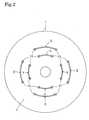
- Fig. 2 shows a rear view of the side mold 1
- Fig. 3 shows a section taken on the line III-III in Fig. 1.
- the side mode 1 shown in Figs. 1 to 3 is not yet provided with flat bars 8 and 9 to be mentioned hereinafter.
- the side mold 1 is an annular steel structure usually made by processing a stainless steel plate.
- the side mold 1 has a concavely curved, annular molding surface 2, and a flat back surface 3 on the opposite outer side.
- exhaust slots 4 having the shape of a circular arc are formed in the side mold 1 on a first circle
- four exhaust slots 5 having the shape of a circular arc are formed in the side mold 1 on a second circle concentric with the first circle and having a diameter greater than the first circle.
- the exhaust slots 4 and 5 extend between and mutually communicating the molding surface 2 and the back surface 3.
- An annular groove 6 is formed in the molding surface 2 so as to correspond to the four exhaust slots 4 formed on the first circle.
- An annular groove 7 is formed in the molding surface 2 so as to correspond to the four exhaust slots 5 formed on the second circle.
- the annular grooves 6 and 7 are formed in parts of the molding surface 2 corresponding to those of the surface of the sidewall of the tire in which bares are likely to be formed.
- the annular grooves 6 and 7 are formed in a predetermined width w of, for example, about 3.01 mm slightly wider than that of the exhaust slots 4 and 5 and in a predetermined depth.
- the inner annular groove 6 has four bottomless sections continuous with the exhaust slot 4, and four bottomed sections 6a, which are arranged alternately in the circumferential direction of the groove 6.
- the outer annular groove 7 has four bottomless sections continuous with the exhaust slot 5, and four bottomed sections 7a, which are arranged alternately in the circumferential direction of the groove 7.
- the bottomless sections are formed in a depth somewhat greater than that of the bottomed sections so that the bottomless sections may be continuous with the exhaust slots 4 and 5.
- Flat bars 8 and 9 respectively having annular shapes are loosely fitted in the annular grooves 6 and 7, respectively.
- the flat bars 8 and 9 are made by processing a steel strip of a predetermined thickness d of, for example, 3 mm.
- the side mold 2 and the flat bars 8 and 9 are made of the same material.
- the thickness of the flat bars 8 and 9 is slightly smaller than the width w of the annular grooves 6 and 7.
- the flat bars 8 and 9 are fitted in the annular grooves 6 and 7, respectively, in a loose fit.
- the flat bars 7 and 9 are seated on the bottoms of the bottomed sections 6a and 7a, respectively, because the depth of the bottomed sections 6a and 7a is smaller than that of the bottomless sections of the annular grooves 6 and 7.
- spaces 6b and 7b continuous with the exhaust slots 4 and 5 are formed under the bottomless sections of the annular grooves 6 and 7 corresponding to the exhaust slots 4 and 5, respectively.
- the inner end surfaces of the flat bars 8 and 9 respectively fitted in the annular grooves 6 and 7 are flush with the molding surface 2.
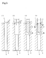
- Figs. 5(1) through 5(4) are enlarged sectional views of the bottomless section of the inner annular groove 6 continuous with the exhaust slot 4.
- a workpiece for forming the side mold 1 is produced by casting.
- the cast workpiece is provided with the exhaust slots 4 and has an unfinished molding surface having a finishing allowance F as shown in Fig. 5(1).
- the annular groove 6 of the predetermined width w is formed in the unfinished molding surface by a turning operation by a lathe as shown in Fig. 5(2).
- the annular groove 6 is slightly wider than the exhaust slots 4.
- the molding surface and the flat bar 8 are ground simultaneously to finish the side mold 1.
- the finishing allowance F of the unfinished molding surface of the workpiece is removed by grinding and, at the same time, the inner end part of the flat bar 8 projecting from the open end of the annular groove 6 is removed by grinding so that the inner end surface of the flat bar 8 is flush with the molding surface 2.
- an exhaust passage extending between the molding surface 2 and the back surface 3 of the side mold 1 is formed by the slits 10, the gaps between the annular groove and the flat bar 8, the space 6b and the exhaust slot 4 to prevent the formation of bares during the vulcanization molding. Since the slits 10 have the very narrow width s between about 0.001 and 0.02 mm, rubber being vulcanized cannot flow into the slits 10 during vulcanization and hence spews are not formed.
- the side mold 1 and the flat bar 8 are made of the same ferrous material and hence have the same coefficient of thermal expansion. Therefore, the width s of the slits 10 remains constant between about 0.001 and 0.02 mm regardless of temperature variation during vulcanization.
- each screw rod 12 has inner ends rotatably connected to eight parts of the outer end surface of the annular flat bar 8. The eight parts are arranged at circumferential intervals.
- Each screw rod 12 is passed through the exhaust slot 4 having the shape of a circular arc and is screwed through a nut 13 embedded in the back surface 3 of the side mold 1.
- An outer end part of the screw rod 12 projects from the back surface 3 of the side mold 1.
- a knob 12a is attached to the outer end part of the screw rod 12 projecting from the back surface 3.
- the inner end surface of the flat bar 8 is flush with the molding surface 2 as shown in Fig. 6(1).
- the flat bar 8 is held in a state shown in Fig. 6(1) during vulcanization.
- the slits 10 have the optimum width s between 0.001 and 0.02 mm.
- the slits 10 are not clogged easily with dirt. Even if the slits 10 are clogged slightly with dirt, the dirt can be easily removed by brushing or the like.
- the knobs 12a of all the screw rods 12 arranged on the back surface 3 of the side mold are turned to push out an end part of the flat bar 8 by several millimeters from the molding surface 2 as shown in Fig. 6(2). Consequently, dirt 15 filling up the slits 10 can be forced out of the slits 10 by the flat bar 8 to remove the dirt 15 from the slits 10.
- the dirt 15 forced out of the slits 10 can be removed from the molding surface 2 by blast cleaning or spray cleaning that sprays a cleaning liquid on the molding surface 2.
- the screw rods 12 are rotated in the opposite direction to bring the flat bar 8 into contact with the bottom surface of the bottomed sections 6a of the annular groove 6.
- the inner end surface of the flat bar 8 becomes flush with the molding surface 2 as shown in Fig. 6(1).
- screw rods 12 have inner ends rotatably connected to the annular flat bar 9, and each screw rod 12 is passed through the exhaust slot 5 and is screwed through a nut 13 and an outer end part of the screw rod 12 projects from the back surface 3 of the side mold 1.
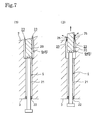
- FIG. 7(1) and 7(2) A flat bar moving mechanism of a vulcanizing mold in a second embodiment of the present invention will be described with reference to Figs. 7(1) and 7(2), in which parts like or corresponding to those of the first embodiment are designated by the same reference characters.
- a side mold 1 of the second embodiment is the same in shape as the side mold 1 of the first embodiment and has a molding surface 2, a back surface 3 and is provided with exhaust slots 4 and annular groove 6.
- a flat bar 20 is the same in shape as the flat bar 8.
- the flat bar 20 and the annular groove 6 define slits 23 of a width between 0.001 and 0.02 mm.
- Rods 21 have externally threaded end parts, respectively. Eight internally threaded holes are arranged at circumferential intervals in the outer end surface of the flat bar 20. The externally threaded end parts of the rods 21 are screwed into the internally threaded holes of the flat bar 20.
- the rods 21 extend through the exhaust slots 4.
- the rods 21 are supported slidably in bearings 22 fitted in bores formed in the back surface 3 so as to coincide with the exhaust slots 4.
- Outer end parts of the rods 21 project from the back surface 3.
- the flat bar 20, similarly to the flat bar 8, is seated on the bottom surfaces of bottomed sections 6a of the annular groove 6 and is held in place.
- the flat bar 20 cannot sink in the annular groove 6 beyond the bottom surfaces of the bottomed sections 6a of the annular groove 6.
- the slits 23 have the very narrow width between 0.001 and 0.02 mm. Thus the slits 23 are not clogged easily with dirt. If the slits 23 are clogged slightly with dirt after the side mold 1 has been used repeatedly for vulcanization, the rods 21 are pushed from the side of the back surface 3 into the exhaust slots 4 so as to project an inner end part of the flat bar 20 from the molding surface 2 by several millimeters as shown in Fig. 7(2). Consequently, dirt 25 filling up the slits 23 can be forced out of the slits 23 by the flat bar 20 to remove the dirt 25 from the slits 23.
- the dirt 25 forced out of the slits 23 can be removed from the molding surface 2 by, for example, a cleaning operation that spouts a cleaning liquid onto the molding surface 2.
- the rods 21 are pulled to seat the flat bar 20 on the bottom surface of the bottomed sections 6a of the annular groove 6.
- the inner end surface of the flat bar 20 becomes flush with the molding surface 2.
- a side mold 51 included in a vulcanizing mold in a third embodiment of the present invention will be described with reference to Figs. 8 to 11(2).
- the side mold 51 has an annular shape which is similar to the annular shape of the side mold 1 of the foregoing embodiment.
- the side mold 51 has a molding surface 52 provided with a single annular groove 56.
- An annular flat bar 58 is fitted in the annular groove 56.
- six exhaust holes 54 and six through holes 55 are formed in the back surface 53 of the side mold 51.
- the six exhaust holes 54 and the six through holes 55 are arranged alternately at equal angular intervals on a circle coaxial with and having a diameter equal to that of the annular groove 56.
- the exhaust holes 54 and the internally threaded holes 5 extend toward the annular groove 56.
- the diameter of the exhaust holes 54 is greater than the width of the annular groove 56.
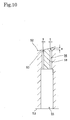
- Slits 60 defined by the annular groove 56 and the flat bar 58 has a width s between 0.001 and 0.02 mm and a depth e between 1 and 2 mm. Gaps between one of the side surfaces of the flat bar 58 and one of the side surfaces of a part excluding an open end part of the annular groove 56 are between about 0.5 and abut 1.0 mm.
- a mouth of each of the through hole 55 on the side of the back surface is enlarged to form a counterbore 55a.
- Hexagonal socket head cap screws 62 are inserted into the through holes 55 and into internally threaded holes formed in the flat bar 58.
- Each of the hexagonal socket head cap screws 62 has a hexagonal socket head 62a of a diameter greater than that of the hexagonal socket head screw 62.
- the hexagonal socket heads 62 are received entirely in the counterbores 55a of the through holes 55.
- the inner end surface of the flat bar 58 to which the hexagonal socket head screws 62 are connected is flush with the molding surface 52 and the bottom surfaces of the hexagonal socket heads 62a of the hexagonal socket head screws 62 are separated from the bottom surfaces of the counterbores 55a, respectively, as shown in Fig. 11 (1).
- An end part of the flat bar 58 can be projected from the molding surface 52 by several millimeters as shown in Fig. 11(2) by pushing the hexagonal socket head screws 62 further into the through holes 55.
- an exhaust passage extending between the molding surface 52 and the back surface 53 of the side mold 51 is formed by the slits 60, the gaps between the annular groove 56 and the flat bar 58, and the exhaust holes 54 to prevent the formation of bares during vulcanization.
- the slits 60 have the very narrow width s between about 0.001 and 0.02 mm, rubber being vulcanized cannot flow into the slits 60 during vulcanization and hence spews are not formed and the slits 60 are not easily clogged with dirt. Even if the slits are clogged slightly with dirt, the dirt can be easily removed from the slits by brushing or the like.
- the six hexagonal socket head cap screws 62 are pushed to push out an end part of the flat bar 58 from the molding surface 52 as shown in Fig. 11(2). Consequently, dirt filling up the slits 60 can be forced out of the slits 60 by the flat bar 58 to remove the dirt from the slits 60. Then, the dirt 15 forced out of the slits 60 can be easily and surely removed from the molding surface 52 by blast cleaning or spray cleaning that sprays a cleaning liquid on the molding surface 52.
- the flat bar 58 thus projected from the molding surface 52 can be returned to the position shown in Fig. 11(1) by pushing the flat bar 58 from the side of the molding surface 52 into the annular groove 56.
- the vulcanizing mold in the third embodiment is provided with the six exhaust holes 54, the suitable number of the exhaust holes is between four and eight.
- the vulcanizing mold in the third embodiment is provided with the six hexagonal socket head cap screws 62, the suitable number of the hexagonal socket head cap screws is between six and eight.
Landscapes
- Engineering & Computer Science (AREA)
- Mechanical Engineering (AREA)
- Moulds For Moulding Plastics Or The Like (AREA)
- Heating, Cooling, Or Curing Plastics Or The Like In General (AREA)
Abstract
Description
- The present invention relates to a tire vulcanizing mold for tire forming.
- A green tire is vulcanized in a tire vulcanizing mold to form a tire. Ventilating holes (vents) are formed in parts of the tire vulcanizing mold corresponding to parts of the tire where bares are likely to be formed, to prevent the formation of marks, due to the generation of bares, in the surface of the tire during vulcanization (For example, refer to Patent Document 1).
- Patent Document 1:
JP-U 59-14832 - If the vents are too large, rubber being vulcanized oozes into the vents and forms spews on the surface of the tire. Additional work for removing the spews is necessary. Too small vents are liable to be clogged with rubber.
- Vents mentioned in
Patent document 1 are through holes each having a cross section of circular shape or other shapes. The inner open ends of the vents are arranged on the molding surface of the tire vulcanizing mold. When the vents are such simple through holes and are formed in a small diameter to prevent the formation of spews, such vent holes having a small diameter are liable to be clogged with dirt. Once the vent holes are clogged with dirt, it is difficult to remove it from the vent holes. - The present invention has been made in view of the foregoing problem and it is an object of the present invention to provide a tire vulcanizing mold provided with vents opening in openings having an improved shape in the molding surface, and capable of preventing the formation of bares and spews, of preventing the vents from being clogged and of ensuring easy cleaning of the vents.
- To attain the above object, a tire vulcanizing mold according to the present invention includes: a side mold provided with exhaust slots having outer open ends opening in the outside surface thereof, and grooves of a predetermined width formed in the molding surface thereof and communicating with inner open ends of the exhaust slots; and flat bars of a predetermined thickness loosely fitted in the grooves such that the inner end surfaces thereof are flush with the molding surface of the side mold.
Desirably, the side mold and the flat bars are made of the same material - Preferably, slits are defined in the molding surface of the side mold by the flat bars and side surfaces of the grooves, and the slits have a width between 0.001 and 0.02 mm.
- Preferably, the vulcanizing mold further includes nuts fixed to the side mold, and screw rods screwed in the nuts and extending from the outside surface of the side mold toward the grooves and having end parts rotatably connected to the flat bars.
- Preferably, rods are extended from the outside surface of the side mold through the side mold toward the grooves and are connected to the flat bars.
- Typically, the side mold is an annular mold for molding a sidewall of a tire, the grooves are annular grooves formed in the annular molding surface of the side mold, and the flat bars are rings fitted in the annular grooves, respectively.
- The present invention also provides a method of manufacturing a vulcanizing mold, which comprises the steps of: making a workpiece for forming a side mold, having an unfinished molding surface having a finishing allowance and provided with exhaust slots mutually communicating an inside surface and an outside surface thereof; forming grooves in the molding surface of the side mold so as to be communicating with inner open ends of the exhaust slots; loosely fitting flat bars in the grooves; and grinding the molding surface of the side mold and the inner end surfaces of the flat bars simultaneously to finish the molding surface and the inner end surfaces of the flat bars.
- The tire vulcanizing mold of the present invention has, in the molding surface thereof, grooves of a suitable width capable of ensuring ventilation, of preventing the formation of bares and spews during vulcanization and of preventing the grooves from being clogged. This can be ensured by loosely fitting flat bars of a predetermined thickness in the grooves to form slits between the side walls of the grooves and the flat bars. Thus, dirt packed in the slits can be easily removed.
- When the flat bars and the mold are made of the same material, the flat bars and the mold have the same coefficient of thermal expansion. Consequently, the width of the slits can be kept constant during vulcanization.
- The width between 0.001 and 0.02 mm of the slits defined by the flat bars and side surfaces of the grooves can prevent the formation of spews and the clogging of the exhaust slots.
- Nuts are fixed to the mold, and screw rods are screwed in the nuts so as to extend from the outside surface of the mold toward the grooves and have end parts rotatably connected to the flat bars. Therefore, even if the slits formed in the molding surface of the mold between the side surfaces of the grooves and the flat bars are clogged with dirt, the dirt can be easily forced out of the slits by turning the screw rods screwed in the nuts to project the flat bars connected to the end parts of the screw rods from the molding surface of the mold. The flat bars can be retracted into the grooves by turning the screw rods in the opposite direction after removing the dirt.
- In the case wherein rods are extended from the outside surface of the mold through the mold toward the grooves and are connected to the flat bars, dirt can be easily forced out of the slits by pushing the screw rods from behind to project the flat bars connected to the end parts of the rods from the molding surface of the mold, even if the slits formed in the molding surface of the mold between the side surfaces of the grooves and the f lat bars are clogged with dirt. Then, the dirt forced out of the slits can be easily and surely removed from the molding surface by blast cleaning or spray cleaning that sprays a cleaning liquid on the molding surface. After the removal of the dirt, the rods are retracted to place the flat bars in the original position.
- Also in the case wherein an annular mold for forming a sidewall of a tire is provided with annular grooves formed in an annular molding surface of the mold, and the flat bars are rings fitted in the annular grooves, ventilation is ensured by the slits defined by side surfaces of the annular grooves and the annular flat bars to prevent the formation of bares and spews in the sidewall of the tire. Further, the slits formed in the molding surface of the mold are not easily clogged with dirt, and dirt can be easily removed from the slits when the slits are clogged with dirt.
- The method of manufacturing a vulcanizing mold according to the present invention grinds the molding surface of the side mold and the inner end surfaces of the flat bars simultaneously to finish the molding surface of the vulcanizing mold. Therefore, the method can easily manufacture the vulcanizing mold provided with the slits, which are formed in the molding surface of the side mold between the side surfaces of the grooves and the flat bars in an optimum width and which are not easily clogged with dirt. Thus, the method enables prevention of the formation of bares and spews in the mold and prevention of formation of marks on the vulcanized tires.
-
- Fig. 1 is a front elevation of a side mold in a first embodiment of the present invention taken from a position facing the molding surface of the side mold;
- Fig. 2 is a rear view of the side mold in the first embodiment;
- Fig. 3 is a sectional view taken on the line III-III in Fig. 1;
- Fig. 4 is a sectional view of the side mold in the first embodiment provided with a flat bar;
- Figs. 5(1), 5(2), 5(3) and 5(4) are enlarged sectional views of assistance in explaining steps of machining a workpiece to form the side mold in the first embodiment, showing a part of the side mold in the first embodiment around an annular groove and an exhaust slot connected to the annular groove;
- Figs. 6(1) and 6(2) are enlarged sectional views taken on the line VI-VI in Fig. 1, showing a flat bar moving mechanism including a flat bar and a screw rod of the vulcanizing mold in the first embodiment in a state where the screw rod is not turned and in a state where the screw rod has been turned, respectively;
- Figs. 7(1) and 7(2) are enlarged sectional views showing a flat bar moving mechanism including a flat bar and a rod of a vulcanizing mold in a second embodiment according to the present invention in a state where the rod is not turned and in a state where the screw rod has been turned, respectively;
- Fig. 8 is a front elevation of a side mold in a third embodiment of the present invention taken from a position facing the molding surface of the side mold;
- Fig. 9 is a rear view of the side mold in the third embodiment;
- Fig. 10 is a sectional view taken on the line x-x in Fig. 8; and
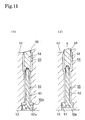
- Figs. 11 (1) and 11 (2) are enlarged sectional views taken on the line XI-XI in Fig. 8, respectively showing a flat bar and a bolt in the third embodiment in a state where the bolt is not operated and a state where the bolt has been operated.
1...Side mold, 2...Molding Surface, 3...Back surface, 4...Exhaust port, 6...Annular groove, 8...Flat bar, 10...Slit, 12...Screw rod, 13...Nut, 15...Dirt , 20...Flat bar, 21...Rod, 22...Bearing, 23...Slit, 25...Dirt, 51...Side mold, 52...Molding surface, 53...Back surface, 54...Exhaust hole, 55...Through hole, 56...Annular groove, 58...Flat bar, 60...Slit, 62...Bolt . - A first embodiment of the present invention will be described with reference to Figs. 1 to 6.
- A vulcanizing mold in a first embodiment of the present invention for forming a tire includes a
side mold 1 for forming a sidewall of a tire. - Fig. 1 shows a front elevation of the
side mold 1 taken from a position facing the molding surface of theside mold 1, Fig. 2 shows a rear view of theside mold 1, and Fig. 3 shows a section taken on the line III-III in Fig. 1. Theside mode 1 shown in Figs. 1 to 3 is not yet provided withflat bars - The
side mold 1 is an annular steel structure usually made by processing a stainless steel plate. Theside mold 1 has a concavely curved,annular molding surface 2, and aflat back surface 3 on the opposite outer side. - Four
exhaust slots 4 having the shape of a circular arc are formed in theside mold 1 on a first circle, and fourexhaust slots 5 having the shape of a circular arc are formed in theside mold 1 on a second circle concentric with the first circle and having a diameter greater than the first circle. Theexhaust slots molding surface 2 and theback surface 3. Anannular groove 6 is formed in themolding surface 2 so as to correspond to the fourexhaust slots 4 formed on the first circle. Anannular groove 7 is formed in themolding surface 2 so as to correspond to the fourexhaust slots 5 formed on the second circle. - The
annular grooves molding surface 2 corresponding to those of the surface of the sidewall of the tire in which bares are likely to be formed. Theannular grooves exhaust slots - The inner
annular groove 6 has four bottomless sections continuous with theexhaust slot 4, and four bottomedsections 6a, which are arranged alternately in the circumferential direction of thegroove 6. The outerannular groove 7 has four bottomless sections continuous with theexhaust slot 5, and four bottomedsections 7a, which are arranged alternately in the circumferential direction of thegroove 7. The bottomless sections are formed in a depth somewhat greater than that of the bottomed sections so that the bottomless sections may be continuous with theexhaust slots -
Flat bars annular grooves flat bars side mold 2 and theflat bars flat bars annular grooves flat bars annular grooves - Referring to Figs. 3 and 4, the
flat bars sections sections annular grooves spaces exhaust slots annular grooves exhaust slots flat bars annular grooves molding surface 2. - Steps of making the
side mold 1 will be described with reference to Fig. 5. - Figs. 5(1) through 5(4) are enlarged sectional views of the bottomless section of the inner
annular groove 6 continuous with theexhaust slot 4. A workpiece for forming theside mold 1 is produced by casting. The cast workpiece is provided with theexhaust slots 4 and has an unfinished molding surface having a finishing allowance F as shown in Fig. 5(1). - The
annular groove 6 of the predetermined width w is formed in the unfinished molding surface by a turning operation by a lathe as shown in Fig. 5(2). Theannular groove 6 is slightly wider than theexhaust slots 4. - Then, the
flat bar 8 of the predetermined thickness d is loosely fitted in theannular groove 6 as shown in Fig. 5(3). At this stage, an inner end part of theflat bar 8 projects from the open end of theannular groove 6 - The molding surface and the
flat bar 8 are ground simultaneously to finish theside mold 1. The finishing allowance F of the unfinished molding surface of the workpiece is removed by grinding and, at the same time, the inner end part of theflat bar 8 projecting from the open end of theannular groove 6 is removed by grinding so that the inner end surface of theflat bar 8 is flush with themolding surface 2. - The outer and inner edges of the open end of the
annular groove 6 are deformed toward each other and the distance between the edges is reduced slightly. Thus slits 10 of a width s between 0.001 and 0.02 mm are formed accurately between the outer side surface of theflat bar 8 and the outer edge of theannular groove 6 and between the inner side surface of theflat bar 8 and the inner edge of theannular groove 6, respectively. - Thus an exhaust passage extending between the
molding surface 2 and theback surface 3 of theside mold 1 is formed by theslits 10, the gaps between the annular groove and theflat bar 8, thespace 6b and theexhaust slot 4 to prevent the formation of bares during the vulcanization molding. Since theslits 10 have the very narrow width s between about 0.001 and 0.02 mm, rubber being vulcanized cannot flow into theslits 10 during vulcanization and hence spews are not formed. - The
side mold 1 and theflat bar 8 are made of the same ferrous material and hence have the same coefficient of thermal expansion. Therefore, the width s of theslits 10 remains constant between about 0.001 and 0.02 mm regardless of temperature variation during vulcanization. - As shown in Fig. 6(1), eight
screw rods 12 have inner ends rotatably connected to eight parts of the outer end surface of the annularflat bar 8. The eight parts are arranged at circumferential intervals. Eachscrew rod 12 is passed through theexhaust slot 4 having the shape of a circular arc and is screwed through anut 13 embedded in theback surface 3 of theside mold 1. An outer end part of thescrew rod 12 projects from theback surface 3 of theside mold 1. Aknob 12a is attached to the outer end part of thescrew rod 12 projecting from theback surface 3. - Normally, the inner end surface of the
flat bar 8 is flush with themolding surface 2 as shown in Fig. 6(1). Theflat bar 8 is held in a state shown in Fig. 6(1) during vulcanization. In the state shown in Fig. 6 (1), theslits 10 have the optimum width s between 0.001 and 0.02 mm. Thus theslits 10 are not clogged easily with dirt. Even if theslits 10 are clogged slightly with dirt, the dirt can be easily removed by brushing or the like. - If dirt enter the
slits 10 into the depth of theslits 10 after theside mold 1 has been used repeatedly for vulcanization and the dirt cannot be easily removed by brushing or the like, theknobs 12a of all thescrew rods 12 arranged on theback surface 3 of the side mold are turned to push out an end part of theflat bar 8 by several millimeters from themolding surface 2 as shown in Fig. 6(2). Consequently,dirt 15 filling up theslits 10 can be forced out of theslits 10 by theflat bar 8 to remove thedirt 15 from theslits 10. - In the state shown in Fig. 6(2), the
dirt 15 forced out of theslits 10 can be removed from themolding surface 2 by blast cleaning or spray cleaning that sprays a cleaning liquid on themolding surface 2. - After the
molding surface 2 has been thus cleaned, thescrew rods 12 are rotated in the opposite direction to bring theflat bar 8 into contact with the bottom surface of the bottomedsections 6a of theannular groove 6. Thus the inner end surface of theflat bar 8 becomes flush with themolding surface 2 as shown in Fig. 6(1). - The construction, effects and functions of the outer
flat bar 9 and theannular groove 7 are the same as those of the innerflat bar 8 and theannular groove 6. - The width of
slits 10 defined by theflat bar 9 and theannular groove 7 is between 0.001 and 0.02 mm,screw rods 12 have inner ends rotatably connected to the annularflat bar 9, and eachscrew rod 12 is passed through theexhaust slot 5 and is screwed through anut 13 and an outer end part of thescrew rod 12 projects from theback surface 3 of theside mold 1. - As apparent from the foregoing description, dirt adhering to the
molding surface 2 of theside mold 1 can be completely removed by a simple cleaning operation. - A flat bar moving mechanism of a vulcanizing mold in a second embodiment of the present invention will be described with reference to Figs. 7(1) and 7(2), in which parts like or corresponding to those of the first embodiment are designated by the same reference characters.
- A
side mold 1 of the second embodiment is the same in shape as theside mold 1 of the first embodiment and has amolding surface 2, aback surface 3 and is provided withexhaust slots 4 andannular groove 6. - A
flat bar 20 is the same in shape as theflat bar 8. Theflat bar 20 and theannular groove 6 defineslits 23 of a width between 0.001 and 0.02 mm. -
Rods 21 have externally threaded end parts, respectively. Eight internally threaded holes are arranged at circumferential intervals in the outer end surface of theflat bar 20. The externally threaded end parts of therods 21 are screwed into the internally threaded holes of theflat bar 20. - The
rods 21 extend through theexhaust slots 4. Therods 21 are supported slidably inbearings 22 fitted in bores formed in theback surface 3 so as to coincide with theexhaust slots 4. Outer end parts of therods 21 project from theback surface 3. Theflat bar 20, similarly to theflat bar 8, is seated on the bottom surfaces of bottomedsections 6a of theannular groove 6 and is held in place. Theflat bar 20 cannot sink in theannular groove 6 beyond the bottom surfaces of the bottomedsections 6a of theannular groove 6. - The
slits 23 have the very narrow width between 0.001 and 0.02 mm. Thus theslits 23 are not clogged easily with dirt. If theslits 23 are clogged slightly with dirt after theside mold 1 has been used repeatedly for vulcanization, therods 21 are pushed from the side of theback surface 3 into theexhaust slots 4 so as to project an inner end part of theflat bar 20 from themolding surface 2 by several millimeters as shown in Fig. 7(2). Consequently,dirt 25 filling up theslits 23 can be forced out of theslits 23 by theflat bar 20 to remove thedirt 25 from theslits 23. - In the state shown in Fig. 7(2), the
dirt 25 forced out of theslits 23 can be removed from themolding surface 2 by, for example, a cleaning operation that spouts a cleaning liquid onto themolding surface 2. After themolding surface 2 has been thus cleaned, therods 21 are pulled to seat theflat bar 20 on the bottom surface of the bottomedsections 6a of theannular groove 6. Thus the inner end surface of theflat bar 20 becomes flush with themolding surface 2. - A
side mold 51 included in a vulcanizing mold in a third embodiment of the present invention will be described with reference to Figs. 8 to 11(2). - The
side mold 51 has an annular shape which is similar to the annular shape of theside mold 1 of the foregoing embodiment. Theside mold 51 has amolding surface 52 provided with a singleannular groove 56. An annularflat bar 58 is fitted in theannular groove 56. - As shown in Fig. 9, six
exhaust holes 54 and six throughholes 55 are formed in theback surface 53 of theside mold 51. The sixexhaust holes 54 and the six throughholes 55 are arranged alternately at equal angular intervals on a circle coaxial with and having a diameter equal to that of theannular groove 56. The exhaust holes 54 and the internally threadedholes 5 extend toward theannular groove 56. As shown in Fig. 10, the diameter of the exhaust holes 54 is greater than the width of theannular groove 56.Slits 60 defined by theannular groove 56 and theflat bar 58 has a width s between 0.001 and 0.02 mm and a depth e between 1 and 2 mm. Gaps between one of the side surfaces of theflat bar 58 and one of the side surfaces of a part excluding an open end part of theannular groove 56 are between about 0.5 and abut 1.0 mm. - Referring to Fig. 11(1), a mouth of each of the through
hole 55 on the side of the back surface is enlarged to form acounterbore 55a. Hexagonal socket head cap screws 62 are inserted into the throughholes 55 and into internally threaded holes formed in theflat bar 58. Each of the hexagonal socket head cap screws 62 has a hexagonal socket head 62a of a diameter greater than that of the hexagonalsocket head screw 62. The hexagonal socket heads 62 are received entirely in thecounterbores 55a of the through holes 55. - Normally, the inner end surface of the
flat bar 58 to which the hexagonal socket head screws 62 are connected is flush with themolding surface 52 and the bottom surfaces of the hexagonal socket heads 62a of the hexagonal socket head screws 62 are separated from the bottom surfaces of thecounterbores 55a, respectively, as shown in Fig. 11 (1). An end part of theflat bar 58 can be projected from themolding surface 52 by several millimeters as shown in Fig. 11(2) by pushing the hexagonal socket head screws 62 further into the through holes 55. - Thus an exhaust passage extending between the
molding surface 52 and theback surface 53 of theside mold 51 is formed by theslits 60, the gaps between theannular groove 56 and theflat bar 58, and the exhaust holes 54 to prevent the formation of bares during vulcanization. - Since the
slits 60 have the very narrow width s between about 0.001 and 0.02 mm, rubber being vulcanized cannot flow into theslits 60 during vulcanization and hence spews are not formed and theslits 60 are not easily clogged with dirt. Even if the slits are clogged slightly with dirt, the dirt can be easily removed from the slits by brushing or the like. - If dirt enter the
slits 60 into the depth of theslits 60 after theside mold 1 has been used repeatedly for vulcanization and the dirt cannot be easily removed by brushing or the like, the six hexagonal socket head cap screws 62 are pushed to push out an end part of theflat bar 58 from themolding surface 52 as shown in Fig. 11(2). Consequently, dirt filling up theslits 60 can be forced out of theslits 60 by theflat bar 58 to remove the dirt from theslits 60. Then, thedirt 15 forced out of theslits 60 can be easily and surely removed from themolding surface 52 by blast cleaning or spray cleaning that sprays a cleaning liquid on themolding surface 52. - The
flat bar 58 thus projected from themolding surface 52 can be returned to the position shown in Fig. 11(1) by pushing theflat bar 58 from the side of themolding surface 52 into theannular groove 56. - Although the vulcanizing mold in the third embodiment is provided with the six
exhaust holes 54, the suitable number of the exhaust holes is between four and eight. Although the vulcanizing mold in the third embodiment is provided with the six hexagonal socket head cap screws 62, the suitable number of the hexagonal socket head cap screws is between six and eight.
Claims (7)
- A tire vulcanizing mold comprising:a side mold provided with exhaust slots having outer open ends opening in an outside surface thereof, and grooves of a predetermined width formed in a molding surface thereof and communicating with inner open ends of the exhaust slots; andflat bars of a predetermined thickness loosely fitted in the grooves such that inner end surfaces thereof are flush with the molding surface of the side mold.
- The tire vulcanizing mold according to claim 1, wherein the side mold and the flat bars are made of the same material.
- The tire vulcanizing mold according to claim 2, wherein slits are defined in the molding surface of the side mold by the flat bars and side surfaces of the grooves, and the slits have a width between 0.001 and 0.02 mm.
- The tire vulcanizing mold according to claim 2 further comprising nuts fixed to the side mold, and screw rods screwed in the nuts and extending from the outside surface of the side mold toward the grooves and having end parts rotatably connected to the flat bars.
- The tire vulcanizing mold according to claim 1 or 2 further comprising rods extended from the outside surface of the side mold through the side mold toward the grooves and connected to the flat bars.
- The tire vulcanizing mold according to claim 1 or 2, wherein the side mold is an annular mold for molding a sidewall of a tire,
the grooves are annular grooves formed in the annular molding surface of the side mold, and
the flat bars are rings fitted in the annular grooves, respectively. - A method of manufacturing a vulcanizing mold comprising the steps of:making a workpiece for forming a side mold, having an unfinished molding surface having a finishing allowance, and provided with exhaust slots mutually communicating an inside surface and an outside surface thereof;forming grooves in the molding surface of the side mold so as to be communicating with inner open ends of the exhaust slots;loosely fitting flat bars in the grooves; andgrinding the molding surface of the side mold and inner end surfaces of the flat bars simultaneously to finish the molding surface and the inner end surfaces of the flat bars.
Applications Claiming Priority (2)
| Application Number | Priority Date | Filing Date | Title |
|---|---|---|---|
| JP2004241019 | 2004-08-20 | ||
| PCT/JP2005/014932 WO2006019087A1 (en) | 2004-08-20 | 2005-08-16 | Vulcanizing mold for molding tire and method of manufacturing the same |
Publications (3)
| Publication Number | Publication Date |
|---|---|
| EP1779989A1 true EP1779989A1 (en) | 2007-05-02 |
| EP1779989A4 EP1779989A4 (en) | 2008-07-23 |
| EP1779989B1 EP1779989B1 (en) | 2010-05-05 |
Family
ID=35907474
Family Applications (1)
| Application Number | Title | Priority Date | Filing Date |
|---|---|---|---|
| EP05780484A Expired - Lifetime EP1779989B1 (en) | 2004-08-20 | 2005-08-16 | Vulcanizing mold for molding tire and method of manufacturing the same |
Country Status (5)
| Country | Link |
|---|---|
| US (1) | US20070259063A1 (en) |
| EP (1) | EP1779989B1 (en) |
| JP (1) | JPWO2006019087A1 (en) |
| DE (1) | DE602005021117D1 (en) |
| WO (1) | WO2006019087A1 (en) |
Cited By (3)
| Publication number | Priority date | Publication date | Assignee | Title |
|---|---|---|---|---|
| WO2009007493A1 (en) * | 2007-07-11 | 2009-01-15 | Wd Racing Oy | Air venting valve of vulcanising mould |
| IT201600126146A1 (en) * | 2016-12-14 | 2018-06-14 | Bridgestone Corp | VULCANIZATION MOLD OF A TREAD STRIP |
| CN112074387A (en) * | 2018-04-30 | 2020-12-11 | 米其林集团总公司 | Molded element with diverging vent slots |
Families Citing this family (9)
| Publication number | Priority date | Publication date | Assignee | Title |
|---|---|---|---|---|
| JP6721700B2 (en) * | 2016-09-28 | 2020-07-15 | Toyo Tire株式会社 | Tire vulcanization mold |
| JP6743161B2 (en) * | 2016-09-28 | 2020-08-19 | Toyo Tire株式会社 | Tire vulcanization mold |
| WO2018061053A1 (en) * | 2016-09-28 | 2018-04-05 | 東洋ゴム工業株式会社 | Tire vulcanization mold |
| US10695996B2 (en) * | 2016-09-28 | 2020-06-30 | Toyo Tire Corporation | Tire vulcanization mold |
| JP6741765B2 (en) * | 2016-09-28 | 2020-08-19 | Toyo Tire株式会社 | Tire vulcanization mold |
| WO2018061055A1 (en) * | 2016-09-28 | 2018-04-05 | 東洋ゴム工業株式会社 | Tire vulcanization mold |
| CN108099235B (en) * | 2017-12-29 | 2020-07-07 | 山东豪迈机械科技股份有限公司 | A tire mold side plate and tire mold |
| CN108582828B (en) * | 2018-05-18 | 2020-07-07 | 山东豪迈机械科技股份有限公司 | Tire mold side plate, tire mold and machining method |
| JP2020142459A (en) * | 2019-03-07 | 2020-09-10 | 住友ゴム工業株式会社 | Tire vulcanization mold |
Family Cites Families (14)
| Publication number | Priority date | Publication date | Assignee | Title |
|---|---|---|---|---|
| US3377662A (en) * | 1965-04-20 | 1968-04-16 | Bridgestone Tire Co Ltd | Metal mold having vent plug means for shaping a plastic article and vulcanizing a rubber article |
| US4576559A (en) * | 1982-12-29 | 1986-03-18 | Bridgestone Tire Co. Ltd. | Vented tire molding mold |
| US4708609A (en) * | 1984-03-22 | 1987-11-24 | Bridgestone Corporation | Tire manufacturing mold |
| US4795331A (en) * | 1986-09-15 | 1989-01-03 | The Goodyear Tire & Rubber Company | Mold vent plug |
| JPS6453816A (en) * | 1987-08-26 | 1989-03-01 | Yokohama Rubber Co Ltd | Sectional type mold for molding tire |
| IT1240295B (en) * | 1990-04-13 | 1993-12-07 | Pirelli | MOLD AND METHOD FOR THE VULCANIZATION OF TIRES AND METHOD FOR MANUFACTURING MOLDS |
| EP0576892B1 (en) * | 1992-07-02 | 1996-01-10 | Compagnie Generale Des Etablissements Michelin-Michelin & Cie | Tire mould, manufacturing process for such a mould and tire molding process using such a mould |
| FR2725933A1 (en) * | 1994-10-20 | 1996-04-26 | Michelin & Cie | EVENTATION OF MOLDS |
| JPH1034664A (en) * | 1996-07-24 | 1998-02-10 | Bridgestone Corp | Mold for vulcanizing rubber molded product and method for producing the same |
| GB9708584D0 (en) * | 1997-04-29 | 1997-06-18 | Sp Tyres Uk Ltd | Mould vents |
| GB2341339A (en) * | 1998-09-08 | 2000-03-15 | Dunlop Tyres Ltd | Improvements to tyre moulds |
| JP4353588B2 (en) * | 1999-07-07 | 2009-10-28 | 株式会社ブリヂストン | Mold for tire molding |
| JP3391756B2 (en) * | 1999-12-07 | 2003-03-31 | 住友ゴム工業株式会社 | Pneumatic tire |
| JP3699362B2 (en) * | 2001-05-02 | 2005-09-28 | 住友ゴム工業株式会社 | Tire vulcanization mold and tire manufacturing method |
-
2005
- 2005-08-16 JP JP2006531801A patent/JPWO2006019087A1/en active Pending
- 2005-08-16 DE DE602005021117T patent/DE602005021117D1/en not_active Expired - Lifetime
- 2005-08-16 WO PCT/JP2005/014932 patent/WO2006019087A1/en not_active Ceased
- 2005-08-16 US US11/660,524 patent/US20070259063A1/en not_active Abandoned
- 2005-08-16 EP EP05780484A patent/EP1779989B1/en not_active Expired - Lifetime
Cited By (7)
| Publication number | Priority date | Publication date | Assignee | Title |
|---|---|---|---|---|
| WO2009007493A1 (en) * | 2007-07-11 | 2009-01-15 | Wd Racing Oy | Air venting valve of vulcanising mould |
| US8287260B2 (en) | 2007-07-11 | 2012-10-16 | Wd Racing Oy | Air venting valve of vulcanising mould |
| US8801996B2 (en) | 2007-07-11 | 2014-08-12 | Wd Racing Oy | Air venting valve of vulcanising mould |
| IT201600126146A1 (en) * | 2016-12-14 | 2018-06-14 | Bridgestone Corp | VULCANIZATION MOLD OF A TREAD STRIP |
| WO2018108967A1 (en) * | 2016-12-14 | 2018-06-21 | Bridgestone Corporation | Tread strip curing mould |
| CN112074387A (en) * | 2018-04-30 | 2020-12-11 | 米其林集团总公司 | Molded element with diverging vent slots |
| CN112074387B (en) * | 2018-04-30 | 2022-05-24 | 米其林集团总公司 | Molded element with diverging vent slots |
Also Published As
| Publication number | Publication date |
|---|---|
| WO2006019087A1 (en) | 2006-02-23 |
| US20070259063A1 (en) | 2007-11-08 |
| EP1779989A4 (en) | 2008-07-23 |
| DE602005021117D1 (en) | 2010-06-17 |
| EP1779989B1 (en) | 2010-05-05 |
| JPWO2006019087A1 (en) | 2008-05-08 |
Similar Documents
| Publication | Publication Date | Title |
|---|---|---|
| EP1779989B1 (en) | Vulcanizing mold for molding tire and method of manufacturing the same | |
| US7290996B2 (en) | Tire vulcanizing mold | |
| EP1998946B1 (en) | Venting valve to be used in venting bores of vulcanization moulds | |
| US8506275B2 (en) | Removable device for moulding a flexible wall in the groove of a tire pattern | |
| JP4983717B2 (en) | Tire vulcanizing mold and manufacturing method thereof | |
| US5066209A (en) | Vented tire mold | |
| CN101293402A (en) | Method for manufacturing stud tire mold | |
| CN107708980A (en) | One group of molded element and mould | |
| US4026512A (en) | Static mold vent | |
| CN106470828B (en) | Mould for vulcanizing a tyre comprising a movable element obtained by laser sintering | |
| EP1652644A1 (en) | Tire mould with a contoured forming surface made of sintered material | |
| US4021168A (en) | Tire mold having washered nails inserted in the vents | |
| US6206336B1 (en) | Venting of molds | |
| CN115066326B (en) | Method for producing a mold section of a vulcanization mold, mold section and vulcanization mold | |
| JP2006312272A (en) | Tire vulcanization mold | |
| JP2892693B2 (en) | Tire mold | |
| JP2002283351A (en) | Rubber molded product vulcanization mold | |
| US8770540B2 (en) | Device and method for manufacturing tire tread features | |
| CN207808556U (en) | A kind of improved tire-mold | |
| HU180356B (en) | Vulcanizing mould for tyres | |
| JP2007045083A (en) | Tire mold and tire manufacturing method | |
| JPH0151324B2 (en) | ||
| JPH0233487B2 (en) | ||
| JPS60232913A (en) | Mold for forming tire and manufacture thereof | |
| EP3600861B1 (en) | Tire mold with interchangeable element having removably attachable lamelle |
Legal Events
| Date | Code | Title | Description |
|---|---|---|---|
| PUAI | Public reference made under article 153(3) epc to a published international application that has entered the european phase |
Free format text: ORIGINAL CODE: 0009012 |
|
| 17P | Request for examination filed |
Effective date: 20070216 |
|
| AK | Designated contracting states |
Kind code of ref document: A1 Designated state(s): DE FR IT |
|
| DAX | Request for extension of the european patent (deleted) | ||
| RBV | Designated contracting states (corrected) |
Designated state(s): DE FR IT |
|
| A4 | Supplementary search report drawn up and despatched |
Effective date: 20080620 |
|
| 17Q | First examination report despatched |
Effective date: 20081013 |
|
| GRAP | Despatch of communication of intention to grant a patent |
Free format text: ORIGINAL CODE: EPIDOSNIGR1 |
|
| GRAS | Grant fee paid |
Free format text: ORIGINAL CODE: EPIDOSNIGR3 |
|
| GRAA | (expected) grant |
Free format text: ORIGINAL CODE: 0009210 |
|
| AK | Designated contracting states |
Kind code of ref document: B1 Designated state(s): DE FR IT |
|
| REF | Corresponds to: |
Ref document number: 602005021117 Country of ref document: DE Date of ref document: 20100617 Kind code of ref document: P |
|
| PGFP | Annual fee paid to national office [announced via postgrant information from national office to epo] |
Ref country code: IT Payment date: 20100818 Year of fee payment: 6 Ref country code: FR Payment date: 20100824 Year of fee payment: 6 Ref country code: DE Payment date: 20100812 Year of fee payment: 6 |
|
| PLBE | No opposition filed within time limit |
Free format text: ORIGINAL CODE: 0009261 |
|
| STAA | Information on the status of an ep patent application or granted ep patent |
Free format text: STATUS: NO OPPOSITION FILED WITHIN TIME LIMIT |
|
| 26N | No opposition filed |
Effective date: 20110208 |
|
| REG | Reference to a national code |
Ref country code: DE Ref legal event code: R097 Ref document number: 602005021117 Country of ref document: DE Effective date: 20110207 |
|
| REG | Reference to a national code |
Ref country code: FR Ref legal event code: ST Effective date: 20120430 |
|
| PG25 | Lapsed in a contracting state [announced via postgrant information from national office to epo] |
Ref country code: IT Free format text: LAPSE BECAUSE OF NON-PAYMENT OF DUE FEES Effective date: 20110816 |
|
| REG | Reference to a national code |
Ref country code: DE Ref legal event code: R119 Ref document number: 602005021117 Country of ref document: DE Effective date: 20120301 |
|
| PG25 | Lapsed in a contracting state [announced via postgrant information from national office to epo] |
Ref country code: FR Free format text: LAPSE BECAUSE OF NON-PAYMENT OF DUE FEES Effective date: 20110831 |
|
| PG25 | Lapsed in a contracting state [announced via postgrant information from national office to epo] |
Ref country code: DE Free format text: LAPSE BECAUSE OF NON-PAYMENT OF DUE FEES Effective date: 20120301 |