EP1779960A1 - Dustproof device of light path system in laser beam machine - Google Patents
Dustproof device of light path system in laser beam machine Download PDFInfo
- Publication number
- EP1779960A1 EP1779960A1 EP06405406A EP06405406A EP1779960A1 EP 1779960 A1 EP1779960 A1 EP 1779960A1 EP 06405406 A EP06405406 A EP 06405406A EP 06405406 A EP06405406 A EP 06405406A EP 1779960 A1 EP1779960 A1 EP 1779960A1
- Authority
- EP
- European Patent Office
- Prior art keywords
- laser beam
- light path
- belt
- steel belt
- path duct
- Prior art date
- Legal status (The legal status is an assumption and is not a legal conclusion. Google has not performed a legal analysis and makes no representation as to the accuracy of the status listed.)
- Granted
Links
- 229910000831 Steel Inorganic materials 0.000 claims abstract description 32
- 239000010959 steel Substances 0.000 claims abstract description 32
- 238000000605 extraction Methods 0.000 claims abstract description 20
- 230000003028 elevating effect Effects 0.000 claims description 4
- 239000000428 dust Substances 0.000 abstract description 4
- 238000006073 displacement reaction Methods 0.000 abstract description 2
- 239000000284 extract Substances 0.000 abstract description 2
- 239000000126 substance Substances 0.000 description 3
- 238000003754 machining Methods 0.000 description 2
- 239000000463 material Substances 0.000 description 2
- 239000000853 adhesive Substances 0.000 description 1
- 230000001070 adhesive effect Effects 0.000 description 1
- 230000006866 deterioration Effects 0.000 description 1
- 230000000694 effects Effects 0.000 description 1
- 239000006247 magnetic powder Substances 0.000 description 1
Images


Classifications
-
- G—PHYSICS
- G02—OPTICS
- G02B—OPTICAL ELEMENTS, SYSTEMS OR APPARATUS
- G02B27/00—Optical systems or apparatus not provided for by any of the groups G02B1/00 - G02B26/00, G02B30/00
- G02B27/0006—Optical systems or apparatus not provided for by any of the groups G02B1/00 - G02B26/00, G02B30/00 with means to keep optical surfaces clean, e.g. by preventing or removing dirt, stains, contamination, condensation
-
- B—PERFORMING OPERATIONS; TRANSPORTING
- B23—MACHINE TOOLS; METAL-WORKING NOT OTHERWISE PROVIDED FOR
- B23K—SOLDERING OR UNSOLDERING; WELDING; CLADDING OR PLATING BY SOLDERING OR WELDING; CUTTING BY APPLYING HEAT LOCALLY, e.g. FLAME CUTTING; WORKING BY LASER BEAM
- B23K26/00—Working by laser beam, e.g. welding, cutting or boring
- B23K26/08—Devices involving relative movement between laser beam and workpiece
- B23K26/0869—Devices involving movement of the laser head in at least one axial direction
-
- B—PERFORMING OPERATIONS; TRANSPORTING
- B23—MACHINE TOOLS; METAL-WORKING NOT OTHERWISE PROVIDED FOR
- B23K—SOLDERING OR UNSOLDERING; WELDING; CLADDING OR PLATING BY SOLDERING OR WELDING; CUTTING BY APPLYING HEAT LOCALLY, e.g. FLAME CUTTING; WORKING BY LASER BEAM
- B23K26/00—Working by laser beam, e.g. welding, cutting or boring
- B23K26/70—Auxiliary operations or equipment
- B23K26/702—Auxiliary equipment
Definitions
- the present invention relates to a dustproof device of a light path system disposed in a laser beam machine and the like.
- a laser beam machine includes a laser beam path system for supplying laser beam output from a fixed laser oscillator to a machining head moving at high speed.
- the laser beam machine for realizing the present invention is equipped with a bed for housing pallets on which workpieces are placed, a column guided via guide rails disposed on both sides of the bed and moving at high speed along the longitudinal direction of the head, and a machining head moving at high speed on guide rails disposed on the column in the direction orthogonal to the direction of movement of the column.
- the laser beam path system disposed on the laser beam machine comprises a light path duct disposed along the longitudinal direction of the bed, and a laser beam extraction unit that moves in synchronization with the column for extracting the laser beam passing through the light path duct and sending the same toward the column.
- the light path duct is a member having a U-shaped cross-section with the upper portion opened, and in the interior thereof is irradiated a laser beam.
- a dustproof device is adopted, in which the upper surface of the light path duct is covered by a steel belt, and the steel belt is elevated via a guide roller only where the laser beam extraction unit passes, so as to enable the laser beam to be extracted.
- Japanese patent application No. 2004-118483 discloses a dustproof unit of a laser beam machine filed by the present applicant.
- a belt-like magnet is disposed on both sides of the light path duct, attracting the steel belt and preventing foreign substances from entering the duct.
- This displacement of the return position of the steel belt accompanying the raising and lowering of the steel belt causes dust to be generated by friction with the guide roller, which causes deterioration of the dustproof operation and also causes damage to the steel belt when the laser beam extraction unit passes at high speed.
- the object of the present invention is to provide a dustproof mechanism of a laser beam machine that solves the problems of the prior art mentioned above.
- the present invention provides a dustproof device of a light path system provided in a laser beam machine comprising a light path duct with an upper portion opened through which laser beam passes, a belt covering the opening of the light path duct, and a laser beam extraction unit traveling along the light path duct and extracting the laser beam by elevating the belt, wherein the belt has a guiding projection formed at a center portion of the upper surface thereof, and the laser beam extraction unit has a guide roller with a groove engaged with the projection on the belt.
- the belt in the dustproof device is a steel belt, and the device further comprises a magnetic belt member for attracting both side portions of the steel belt disposed on the upper surface of the light path duct.
- the laser beam extraction unit comprises a guide roller for pressing the belt onto the light path duct, a straight roller disposed on the lower side of the belt and guiding the belt to an elevated position, and a guide roller disposed on the upper side of the belt and sandwiching the belt with the straight roller.
- a guiding projection is formed on the upper surface of the steel belt covering the upper opening of the light path duct, and the laser beam extraction unit extracts the laser beam by traveling on the light path duct and elevating the belt.
- the laser beam extraction unit is equipped with a guide roller having a groove engaged with the projection on the steel belt, so as to prevent meandering of the steel belt and improve the dust proofing effect of the light path system of the laser beam.
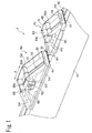
- FIG. 1 is a perspective view showing the relevant portion of a light path system of the laser beam machine according to the present invention
- FIG. 2 is a cross-sectional view of the light path duct
- FIG. 3 is an explanatory view of the steel belt and the guide roller for realizing a dustproof arrangement.
- the light path system of a laser beam machine denoted as a whole by reference number 1 has a light path duct 10 and a laser beam extraction unit 50 and 70 that moves at high speed on the light path duct in the direction of arrow A.
- Necessary devices such as a mirror 52 and the like are disposed on the laser beam extraction unit 50.
- the light path duct 10 has a substantially U-shaped cross-sectional shape, forming therein a space 12 through which laser beam passes.
- the upper portion of the light path duct 10 is opened, with flanges 14 formed on both inner sides of the upper end thereof.
- a magnetic rubber belt 18 formed for example by impregnating rubber with magnetic powder material.
- the magnetic rubber belt 18 attracts the lower surface on both side ends of a steel belt 30 covering the upper opening of the light path duct 10, preventing foreign substances from entering the light path duct 10.
- a guiding projection 32 is disposed on the center portion of the upper surface of the steel belt 30.
- This projection 32 is formed for example by forming a belt-like body from rubber material and bonding the same via an adhesive or the like on the upper surface of the steel belt 30.
- FIGS. 1 through 3 illustrate the layout of guide rollers disposed on the laser beam extraction unit 50.
- the laser beam extraction unit 50 has six guide rollers mounted to a frame 51.
- Four guide rollers 61, 62, 63 and 64 disposed on the upper side of the steel belt 30 has V-shaped grooves 61 a, 62a, 63a and 64a formed respectively on the center area thereof.
- the grooves on the guide rollers are engaged with the projection 32 on the steel belt 30, restricting the lateral movement of the steel belt 30.
- Guide rollers 62 and 63 form a space for extracting the laser beam in the upper direction from the light path duct 10 by elevating the steel belt 30.
- straight rollers 65 and 66 for sandwiching and guiding the steel belt together with the guide roller 62 are disposed on the lower side of the steel belt 30 under the guide roller 62. Since the straight roller 65 contacts the lower surface of the steel belt having no projection, a cylindrical straight roller is used.
- Dust proofing walls 16 are formed above the flanges 14 of the light path duct 10.
- a skirt unit 54 covering the upper end the walls 16 is disposed below the frame 51 of the laser beam extraction unit 50.
- a so-called labyrinth structure is created between the fixed walls 16 and the moving skirt unit 54, by which foreign substances are prevented from entering the light path 12.
Landscapes
- Physics & Mathematics (AREA)
- Optics & Photonics (AREA)
- Engineering & Computer Science (AREA)
- Plasma & Fusion (AREA)
- Mechanical Engineering (AREA)
- General Physics & Mathematics (AREA)
- Laser Beam Processing (AREA)
- Prevention Of Fouling (AREA)
Abstract
Description
- The present invention relates to a dustproof device of a light path system disposed in a laser beam machine and the like.
- A laser beam machine includes a laser beam path system for supplying laser beam output from a fixed laser oscillator to a machining head moving at high speed.
- The laser beam machine for realizing the present invention is equipped with a bed for housing pallets on which workpieces are placed, a column guided via guide rails disposed on both sides of the bed and moving at high speed along the longitudinal direction of the head, and a machining head moving at high speed on guide rails disposed on the column in the direction orthogonal to the direction of movement of the column.
- The laser beam path system disposed on the laser beam machine comprises a light path duct disposed along the longitudinal direction of the bed, and a laser beam extraction unit that moves in synchronization with the column for extracting the laser beam passing through the light path duct and sending the same toward the column.
- The light path duct is a member having a U-shaped cross-section with the upper portion opened, and in the interior thereof is irradiated a laser beam. A dustproof device is adopted, in which the upper surface of the light path duct is covered by a steel belt, and the steel belt is elevated via a guide roller only where the laser beam extraction unit passes, so as to enable the laser beam to be extracted.
-
Japanese patent application No. 2004-118483 - In the dustproof unit of a laser beam machine disclosed in the above-mentioned patent application, a belt-like magnet is disposed on both sides of the light path duct, attracting the steel belt and preventing foreign substances from entering the duct.
- However, there is a drawback in that when the laser beam extraction unit passes, the steel belt is forcibly elevated by the guide roller, and when it is lowered onto the magnet after the passing of the extraction unit, the belt is displaced and not returned to its original position.
- This displacement of the return position of the steel belt accompanying the raising and lowering of the steel belt causes dust to be generated by friction with the guide roller, which causes deterioration of the dustproof operation and also causes damage to the steel belt when the laser beam extraction unit passes at high speed.
- The object of the present invention is to provide a dustproof mechanism of a laser beam machine that solves the problems of the prior art mentioned above.
- In order to achieve the above object, the present invention provides a dustproof device of a light path system provided in a laser beam machine comprising a light path duct with an upper portion opened through which laser beam passes, a belt covering the opening of the light path duct, and a laser beam extraction unit traveling along the light path duct and extracting the laser beam by elevating the belt, wherein the belt has a guiding projection formed at a center portion of the upper surface thereof, and the laser beam extraction unit has a guide roller with a groove engaged with the projection on the belt.
- Furthermore, the belt in the dustproof device is a steel belt, and the device further comprises a magnetic belt member for attracting both side portions of the steel belt disposed on the upper surface of the light path duct.
- Even further, the laser beam extraction unit comprises a guide roller for pressing the belt onto the light path duct, a straight roller disposed on the lower side of the belt and guiding the belt to an elevated position, and a guide roller disposed on the upper side of the belt and sandwiching the belt with the straight roller.
- According to the present invention arranged as described above, a guiding projection is formed on the upper surface of the steel belt covering the upper opening of the light path duct, and the laser beam extraction unit extracts the laser beam by traveling on the light path duct and elevating the belt. The laser beam extraction unit is equipped with a guide roller having a groove engaged with the projection on the steel belt, so as to prevent meandering of the steel belt and improve the dust proofing effect of the light path system of the laser beam.
-
- FIG. 1 is a perspective view showing the relevant portion of a light path system of the laser beam machine;
- FIG. 2 is a cross-sectional view of a light path duct; and
- FIG. 3 is an explanatory view showing the steel belt and the guide roller.
- FIG. 1 is a perspective view showing the relevant portion of a light path system of the laser beam machine according to the present invention, FIG. 2 is a cross-sectional view of the light path duct, and FIG. 3 is an explanatory view of the steel belt and the guide roller for realizing a dustproof arrangement.
- The light path system of a laser beam machine denoted as a whole by reference number 1 has a
light path duct 10 and a laserbeam extraction unit mirror 52 and the like are disposed on the laserbeam extraction unit 50. - As shown in FIG. 2, the
light path duct 10 has a substantially U-shaped cross-sectional shape, forming therein aspace 12 through which laser beam passes. The upper portion of thelight path duct 10 is opened, withflanges 14 formed on both inner sides of the upper end thereof. On the upper surface of theflange 14 is disposed amagnetic rubber belt 18 formed for example by impregnating rubber with magnetic powder material. - The
magnetic rubber belt 18 attracts the lower surface on both side ends of asteel belt 30 covering the upper opening of thelight path duct 10, preventing foreign substances from entering thelight path duct 10. - A guiding
projection 32 is disposed on the center portion of the upper surface of thesteel belt 30. Thisprojection 32 is formed for example by forming a belt-like body from rubber material and bonding the same via an adhesive or the like on the upper surface of thesteel belt 30. - FIGS. 1 through 3 illustrate the layout of guide rollers disposed on the laser
beam extraction unit 50. - The laser
beam extraction unit 50 has six guide rollers mounted to aframe 51. Fourguide rollers steel belt 30 has V-shaped grooves - The grooves on the guide rollers are engaged with the
projection 32 on thesteel belt 30, restricting the lateral movement of thesteel belt 30.Guide rollers light path duct 10 by elevating thesteel belt 30. In order to realize this arrangement,straight rollers guide roller 62 are disposed on the lower side of thesteel belt 30 under theguide roller 62. Since thestraight roller 65 contacts the lower surface of the steel belt having no projection, a cylindrical straight roller is used. -
Dust proofing walls 16 are formed above theflanges 14 of thelight path duct 10. Askirt unit 54 covering the upper end thewalls 16 is disposed below theframe 51 of the laserbeam extraction unit 50. In other words, a so-called labyrinth structure is created between thefixed walls 16 and the movingskirt unit 54, by which foreign substances are prevented from entering thelight path 12.
Claims (3)
- A dustproof device of a light path system provided in a laser beam machine comprising:a light path duct with an upper portion opened through which laser beam passes;a belt covering the opening of the light path duct; anda laser beam extraction unit traveling along the light path duct and elevating the belt to extract the laser beam;wherein the belt has a guiding projection formed at a center portion of the upper surface thereof, and the laser beam extraction unit has a guide roller with a groove engaged with the projection on the belt.
- The dustproof device of a light path system provided in a laser beam machine according to claim 1, wherein the belt is a steel belt, and further comprising a magnetic belt member for attracting both side portions of the steel belt disposed on the upper surface of the light path duct.
- The dustproof device of a light path system provided in a laser beam machine according to claim 1, wherein the laser beam extraction unit comprises a guide roller for pressing the belt onto the light path duct, a straight roller disposed on the lower side of the belt and guiding the belt to an elevated position, and a guide roller disposed on the upper side of the belt and sandwiching the belt with the straight roller.
Applications Claiming Priority (1)
| Application Number | Priority Date | Filing Date | Title |
|---|---|---|---|
| JP2005315601A JP5014615B2 (en) | 2005-10-31 | 2005-10-31 | Laser processing machine dust path system |
Publications (2)
| Publication Number | Publication Date |
|---|---|
| EP1779960A1 true EP1779960A1 (en) | 2007-05-02 |
| EP1779960B1 EP1779960B1 (en) | 2008-05-21 |
Family
ID=37708431
Family Applications (1)
| Application Number | Title | Priority Date | Filing Date |
|---|---|---|---|
| EP06405406A Ceased EP1779960B1 (en) | 2005-10-31 | 2006-09-27 | Dustproof device of light path system in laser beam machine |
Country Status (5)
| Country | Link |
|---|---|
| US (1) | US7273999B2 (en) |
| EP (1) | EP1779960B1 (en) |
| JP (1) | JP5014615B2 (en) |
| CN (1) | CN100513051C (en) |
| DE (1) | DE602006001284D1 (en) |
Families Citing this family (2)
| Publication number | Priority date | Publication date | Assignee | Title |
|---|---|---|---|---|
| US20130032580A1 (en) * | 2010-11-29 | 2013-02-07 | Mitsubishi Electric Corporation | Optical path structure of laser processing machine |
| CN112872615B (en) * | 2021-01-13 | 2022-08-02 | 湖北长平汽车装备有限公司 | Thin steel plate laser cutting control method |
Citations (3)
| Publication number | Priority date | Publication date | Assignee | Title |
|---|---|---|---|---|
| US5472367A (en) * | 1993-10-07 | 1995-12-05 | Omax Corporation | Machine tool apparatus and linear motion track therefor |
| WO2001032350A1 (en) * | 1999-11-04 | 2001-05-10 | Lillbacka Jetair Oy | Laser beam guide |
| EP1566235A1 (en) * | 2004-02-18 | 2005-08-24 | Yamazaki Mazak Kabushiki Kaisha | Laser beam working machine with first and second beam guide portions for shortening the length of the optical path, the latter being held constant during laser processing |
Family Cites Families (5)
| Publication number | Priority date | Publication date | Assignee | Title |
|---|---|---|---|---|
| JPS62502326A (en) * | 1985-03-26 | 1987-09-10 | クカ シユヴアイスアンラ−ゲン ウント ロボ−タ− ゲゼルシヤフト ミツト ベシユレンクテル ハフツング | A lock transmission for producing relative movement between two mutually guided mechanical parts |
| JPS6418034U (en) * | 1987-07-23 | 1989-01-30 | ||
| JPH0679793B2 (en) * | 1988-03-29 | 1994-10-12 | 株式会社ハイテクノ | Laser cutting equipment |
| JP2003312828A (en) * | 2002-04-23 | 2003-11-06 | Nobuyuki Tsuboi | Guide rail for travel |
| JP4676161B2 (en) * | 2004-04-14 | 2011-04-27 | ヤマザキマザック株式会社 | Laser processing machine |
-
2005
- 2005-10-31 JP JP2005315601A patent/JP5014615B2/en not_active Expired - Fee Related
-
2006
- 2006-09-27 EP EP06405406A patent/EP1779960B1/en not_active Ceased
- 2006-09-27 DE DE602006001284T patent/DE602006001284D1/en active Active
- 2006-10-05 US US11/538,842 patent/US7273999B2/en not_active Expired - Fee Related
- 2006-10-11 CN CNB2006101423757A patent/CN100513051C/en not_active Expired - Fee Related
Patent Citations (3)
| Publication number | Priority date | Publication date | Assignee | Title |
|---|---|---|---|---|
| US5472367A (en) * | 1993-10-07 | 1995-12-05 | Omax Corporation | Machine tool apparatus and linear motion track therefor |
| WO2001032350A1 (en) * | 1999-11-04 | 2001-05-10 | Lillbacka Jetair Oy | Laser beam guide |
| EP1566235A1 (en) * | 2004-02-18 | 2005-08-24 | Yamazaki Mazak Kabushiki Kaisha | Laser beam working machine with first and second beam guide portions for shortening the length of the optical path, the latter being held constant during laser processing |
Also Published As
| Publication number | Publication date |
|---|---|
| US7273999B2 (en) | 2007-09-25 |
| CN1958212A (en) | 2007-05-09 |
| JP2007118057A (en) | 2007-05-17 |
| US20070098434A1 (en) | 2007-05-03 |
| CN100513051C (en) | 2009-07-15 |
| DE602006001284D1 (en) | 2008-07-03 |
| EP1779960B1 (en) | 2008-05-21 |
| JP5014615B2 (en) | 2012-08-29 |
Similar Documents
| Publication | Publication Date | Title |
|---|---|---|
| US20120285278A1 (en) | Actuator available in controlled environment | |
| JPH0675813B2 (en) | Protective device for the guideways of two machine parts which are tangentially attached to each other and are movably supported in a longitudinal direction | |
| KR950024951A (en) | Warehouse device for automatic warehouse | |
| EP1779960B1 (en) | Dustproof device of light path system in laser beam machine | |
| KR102402362B1 (en) | Transport apparatus, exposure apparatus and transport method | |
| EP1779959B1 (en) | Seal device of light path system in laser beam machine | |
| JPH08216071A (en) | Robot | |
| ATE231221T1 (en) | RODLESS LINEAR DRIVE AND ASSOCIATED HOUSING | |
| EP1232037B1 (en) | Laser beam guide | |
| US8419280B2 (en) | Thin slide unit | |
| NL1032371C2 (en) | Displacement device and component placement device. | |
| JP2009072821A (en) | Linear motor type clamp moving mechanism | |
| JP7034239B1 (en) | Passenger conveyor | |
| JP5191389B2 (en) | Linear guide device | |
| ATE280659T1 (en) | DEVICE FOR FIXING AND GUIDING A BEARING IN A MACHINE FRAME | |
| JP4676161B2 (en) | Laser processing machine | |
| KR101797309B1 (en) | Appratus for cutting material | |
| EP0581234A1 (en) | Handling apparatus for automatic warehousing arrangement | |
| JP2003311580A (en) | Raceway protective bellows support for machine tool | |
| SE9603163L (en) | Control system between a slide and a guide | |
| KR20250010265A (en) | Electrode tracking device | |
| CN108638339A (en) | Crown-block type graphite machine | |
| GB2136062A (en) | A linear ball-bearing for guiding a workpiece carriage of a machine saw | |
| SE9503463L (en) | Device at the end of a sheet cutter | |
| JP3131668U (en) | Plate-like member fastening structure and guide device provided with the same |
Legal Events
| Date | Code | Title | Description |
|---|---|---|---|
| PUAI | Public reference made under article 153(3) epc to a published international application that has entered the european phase |
Free format text: ORIGINAL CODE: 0009012 |
|
| AK | Designated contracting states |
Kind code of ref document: A1 Designated state(s): AT BE BG CH CY CZ DE DK EE ES FI FR GB GR HU IE IS IT LI LT LU LV MC NL PL PT RO SE SI SK TR |
|
| AX | Request for extension of the european patent |
Extension state: AL BA HR MK YU |
|
| 17P | Request for examination filed |
Effective date: 20070802 |
|
| RAP1 | Party data changed (applicant data changed or rights of an application transferred) |
Owner name: YAMAZAKI MAZAK CORPORATION |
|
| GRAP | Despatch of communication of intention to grant a patent |
Free format text: ORIGINAL CODE: EPIDOSNIGR1 |
|
| AKX | Designation fees paid |
Designated state(s): DE FR GB IT |
|
| GRAS | Grant fee paid |
Free format text: ORIGINAL CODE: EPIDOSNIGR3 |
|
| GRAA | (expected) grant |
Free format text: ORIGINAL CODE: 0009210 |
|
| AK | Designated contracting states |
Kind code of ref document: B1 Designated state(s): DE FR GB IT |
|
| REG | Reference to a national code |
Ref country code: GB Ref legal event code: FG4D |
|
| REF | Corresponds to: |
Ref document number: 602006001284 Country of ref document: DE Date of ref document: 20080703 Kind code of ref document: P |
|
| PLBE | No opposition filed within time limit |
Free format text: ORIGINAL CODE: 0009261 |
|
| STAA | Information on the status of an ep patent application or granted ep patent |
Free format text: STATUS: NO OPPOSITION FILED WITHIN TIME LIMIT |
|
| 26N | No opposition filed |
Effective date: 20090224 |
|
| REG | Reference to a national code |
Ref country code: FR Ref legal event code: PLFP Year of fee payment: 11 |
|
| REG | Reference to a national code |
Ref country code: FR Ref legal event code: PLFP Year of fee payment: 12 |
|
| PGFP | Annual fee paid to national office [announced via postgrant information from national office to epo] |
Ref country code: DE Payment date: 20170920 Year of fee payment: 12 Ref country code: FR Payment date: 20170810 Year of fee payment: 12 Ref country code: IT Payment date: 20170925 Year of fee payment: 12 Ref country code: GB Payment date: 20170927 Year of fee payment: 12 |
|
| REG | Reference to a national code |
Ref country code: DE Ref legal event code: R119 Ref document number: 602006001284 Country of ref document: DE |
|
| GBPC | Gb: european patent ceased through non-payment of renewal fee |
Effective date: 20180927 |
|
| PG25 | Lapsed in a contracting state [announced via postgrant information from national office to epo] |
Ref country code: IT Free format text: LAPSE BECAUSE OF NON-PAYMENT OF DUE FEES Effective date: 20180927 Ref country code: DE Free format text: LAPSE BECAUSE OF NON-PAYMENT OF DUE FEES Effective date: 20190402 |
|
| PG25 | Lapsed in a contracting state [announced via postgrant information from national office to epo] |
Ref country code: FR Free format text: LAPSE BECAUSE OF NON-PAYMENT OF DUE FEES Effective date: 20180930 |
|
| PG25 | Lapsed in a contracting state [announced via postgrant information from national office to epo] |
Ref country code: GB Free format text: LAPSE BECAUSE OF NON-PAYMENT OF DUE FEES Effective date: 20180927 |