EP1779803B1 - Roller bearing, medical or dental hand-piece including the same - Google Patents
Roller bearing, medical or dental hand-piece including the same Download PDFInfo
- Publication number
- EP1779803B1 EP1779803B1 EP06023741A EP06023741A EP1779803B1 EP 1779803 B1 EP1779803 B1 EP 1779803B1 EP 06023741 A EP06023741 A EP 06023741A EP 06023741 A EP06023741 A EP 06023741A EP 1779803 B1 EP1779803 B1 EP 1779803B1
- Authority
- EP
- European Patent Office
- Prior art keywords
- roller
- roller bearing
- handpiece
- medical
- bearing
- Prior art date
- Legal status (The legal status is an assumption and is not a legal conclusion. Google has not performed a legal analysis and makes no representation as to the accuracy of the status listed.)
- Expired - Lifetime
Links
Images


Classifications
-
- F—MECHANICAL ENGINEERING; LIGHTING; HEATING; WEAPONS; BLASTING
- F16—ENGINEERING ELEMENTS AND UNITS; GENERAL MEASURES FOR PRODUCING AND MAINTAINING EFFECTIVE FUNCTIONING OF MACHINES OR INSTALLATIONS; THERMAL INSULATION IN GENERAL
- F16C—SHAFTS; FLEXIBLE SHAFTS; ELEMENTS OR CRANKSHAFT MECHANISMS; ROTARY BODIES OTHER THAN GEARING ELEMENTS; BEARINGS
- F16C19/00—Bearings with rolling contact, for exclusively rotary movement
- F16C19/54—Systems consisting of a plurality of bearings with rolling friction
-
- A—HUMAN NECESSITIES
- A61—MEDICAL OR VETERINARY SCIENCE; HYGIENE
- A61C—DENTISTRY; APPARATUS OR METHODS FOR ORAL OR DENTAL HYGIENE
- A61C1/00—Dental machines for boring or cutting ; General features of dental machines or apparatus, e.g. hand-piece design
- A61C1/02—Dental machines for boring or cutting ; General features of dental machines or apparatus, e.g. hand-piece design characterised by the drive of the dental tools
- A61C1/05—Dental machines for boring or cutting ; General features of dental machines or apparatus, e.g. hand-piece design characterised by the drive of the dental tools with turbine drive
-
- A—HUMAN NECESSITIES
- A61—MEDICAL OR VETERINARY SCIENCE; HYGIENE
- A61C—DENTISTRY; APPARATUS OR METHODS FOR ORAL OR DENTAL HYGIENE
- A61C1/00—Dental machines for boring or cutting ; General features of dental machines or apparatus, e.g. hand-piece design
- A61C1/02—Dental machines for boring or cutting ; General features of dental machines or apparatus, e.g. hand-piece design characterised by the drive of the dental tools
- A61C1/06—Dental machines for boring or cutting ; General features of dental machines or apparatus, e.g. hand-piece design characterised by the drive of the dental tools with electric drive
-
- A—HUMAN NECESSITIES
- A61—MEDICAL OR VETERINARY SCIENCE; HYGIENE
- A61C—DENTISTRY; APPARATUS OR METHODS FOR ORAL OR DENTAL HYGIENE
- A61C1/00—Dental machines for boring or cutting ; General features of dental machines or apparatus, e.g. hand-piece design
- A61C1/08—Machine parts specially adapted for dentistry
- A61C1/18—Flexible shafts; Clutches or the like; Bearings or lubricating arrangements; Drives or transmissions
- A61C1/181—Bearings or lubricating arrangements, e.g. air-cushion bearings
-
- A—HUMAN NECESSITIES
- A61—MEDICAL OR VETERINARY SCIENCE; HYGIENE
- A61C—DENTISTRY; APPARATUS OR METHODS FOR ORAL OR DENTAL HYGIENE
- A61C1/00—Dental machines for boring or cutting ; General features of dental machines or apparatus, e.g. hand-piece design
- A61C1/08—Machine parts specially adapted for dentistry
- A61C1/18—Flexible shafts; Clutches or the like; Bearings or lubricating arrangements; Drives or transmissions
- A61C1/185—Drives or transmissions
-
- A—HUMAN NECESSITIES
- A61—MEDICAL OR VETERINARY SCIENCE; HYGIENE
- A61C—DENTISTRY; APPARATUS OR METHODS FOR ORAL OR DENTAL HYGIENE
- A61C13/00—Dental prostheses; Making same
- A61C13/225—Fastening prostheses in the mouth
- A61C13/235—Magnetic fastening
-
- F—MECHANICAL ENGINEERING; LIGHTING; HEATING; WEAPONS; BLASTING
- F01—MACHINES OR ENGINES IN GENERAL; ENGINE PLANTS IN GENERAL; STEAM ENGINES
- F01D—NON-POSITIVE DISPLACEMENT MACHINES OR ENGINES, e.g. STEAM TURBINES
- F01D15/00—Adaptations of machines or engines for special use; Combinations of engines with devices driven thereby
- F01D15/06—Adaptations for driving, or combinations with, hand-held tools or the like control thereof
-
- F—MECHANICAL ENGINEERING; LIGHTING; HEATING; WEAPONS; BLASTING
- F01—MACHINES OR ENGINES IN GENERAL; ENGINE PLANTS IN GENERAL; STEAM ENGINES
- F01D—NON-POSITIVE DISPLACEMENT MACHINES OR ENGINES, e.g. STEAM TURBINES
- F01D25/00—Component parts, details, or accessories, not provided for in, or of interest apart from, other groups
- F01D25/16—Arrangement of bearings; Supporting or mounting bearings in casings
-
- F—MECHANICAL ENGINEERING; LIGHTING; HEATING; WEAPONS; BLASTING
- F16—ENGINEERING ELEMENTS AND UNITS; GENERAL MEASURES FOR PRODUCING AND MAINTAINING EFFECTIVE FUNCTIONING OF MACHINES OR INSTALLATIONS; THERMAL INSULATION IN GENERAL
- F16C—SHAFTS; FLEXIBLE SHAFTS; ELEMENTS OR CRANKSHAFT MECHANISMS; ROTARY BODIES OTHER THAN GEARING ELEMENTS; BEARINGS
- F16C19/00—Bearings with rolling contact, for exclusively rotary movement
- F16C19/02—Bearings with rolling contact, for exclusively rotary movement with bearing balls essentially of the same size in one or more circular rows
- F16C19/14—Bearings with rolling contact, for exclusively rotary movement with bearing balls essentially of the same size in one or more circular rows for both radial and axial load
- F16C19/18—Bearings with rolling contact, for exclusively rotary movement with bearing balls essentially of the same size in one or more circular rows for both radial and axial load with two or more rows of balls
- F16C19/181—Bearings with rolling contact, for exclusively rotary movement with bearing balls essentially of the same size in one or more circular rows for both radial and axial load with two or more rows of balls with angular contact
- F16C19/183—Bearings with rolling contact, for exclusively rotary movement with bearing balls essentially of the same size in one or more circular rows for both radial and axial load with two or more rows of balls with angular contact with two rows at opposite angles
- F16C19/184—Bearings with rolling contact, for exclusively rotary movement with bearing balls essentially of the same size in one or more circular rows for both radial and axial load with two or more rows of balls with angular contact with two rows at opposite angles in O-arrangement
-
- F—MECHANICAL ENGINEERING; LIGHTING; HEATING; WEAPONS; BLASTING
- F16—ENGINEERING ELEMENTS AND UNITS; GENERAL MEASURES FOR PRODUCING AND MAINTAINING EFFECTIVE FUNCTIONING OF MACHINES OR INSTALLATIONS; THERMAL INSULATION IN GENERAL
- F16C—SHAFTS; FLEXIBLE SHAFTS; ELEMENTS OR CRANKSHAFT MECHANISMS; ROTARY BODIES OTHER THAN GEARING ELEMENTS; BEARINGS
- F16C19/00—Bearings with rolling contact, for exclusively rotary movement
- F16C19/02—Bearings with rolling contact, for exclusively rotary movement with bearing balls essentially of the same size in one or more circular rows
- F16C19/14—Bearings with rolling contact, for exclusively rotary movement with bearing balls essentially of the same size in one or more circular rows for both radial and axial load
- F16C19/18—Bearings with rolling contact, for exclusively rotary movement with bearing balls essentially of the same size in one or more circular rows for both radial and axial load with two or more rows of balls
- F16C19/188—Bearings with rolling contact, for exclusively rotary movement with bearing balls essentially of the same size in one or more circular rows for both radial and axial load with two or more rows of balls with at least one row for radial load in combination with at least one row for axial load
-
- F—MECHANICAL ENGINEERING; LIGHTING; HEATING; WEAPONS; BLASTING
- F16—ENGINEERING ELEMENTS AND UNITS; GENERAL MEASURES FOR PRODUCING AND MAINTAINING EFFECTIVE FUNCTIONING OF MACHINES OR INSTALLATIONS; THERMAL INSULATION IN GENERAL
- F16C—SHAFTS; FLEXIBLE SHAFTS; ELEMENTS OR CRANKSHAFT MECHANISMS; ROTARY BODIES OTHER THAN GEARING ELEMENTS; BEARINGS
- F16C19/00—Bearings with rolling contact, for exclusively rotary movement
- F16C19/54—Systems consisting of a plurality of bearings with rolling friction
- F16C19/541—Systems consisting of juxtaposed rolling bearings including at least one angular contact bearing
- F16C19/542—Systems consisting of juxtaposed rolling bearings including at least one angular contact bearing with two rolling bearings with angular contact
- F16C19/543—Systems consisting of juxtaposed rolling bearings including at least one angular contact bearing with two rolling bearings with angular contact in O-arrangement
-
- F—MECHANICAL ENGINEERING; LIGHTING; HEATING; WEAPONS; BLASTING
- F16—ENGINEERING ELEMENTS AND UNITS; GENERAL MEASURES FOR PRODUCING AND MAINTAINING EFFECTIVE FUNCTIONING OF MACHINES OR INSTALLATIONS; THERMAL INSULATION IN GENERAL
- F16C—SHAFTS; FLEXIBLE SHAFTS; ELEMENTS OR CRANKSHAFT MECHANISMS; ROTARY BODIES OTHER THAN GEARING ELEMENTS; BEARINGS
- F16C27/00—Elastic or yielding bearings or bearing supports, for exclusively rotary movement
- F16C27/06—Elastic or yielding bearings or bearing supports, for exclusively rotary movement by means of parts of rubber or like materials
- F16C27/066—Ball or roller bearings
-
- F—MECHANICAL ENGINEERING; LIGHTING; HEATING; WEAPONS; BLASTING
- F16—ENGINEERING ELEMENTS AND UNITS; GENERAL MEASURES FOR PRODUCING AND MAINTAINING EFFECTIVE FUNCTIONING OF MACHINES OR INSTALLATIONS; THERMAL INSULATION IN GENERAL
- F16C—SHAFTS; FLEXIBLE SHAFTS; ELEMENTS OR CRANKSHAFT MECHANISMS; ROTARY BODIES OTHER THAN GEARING ELEMENTS; BEARINGS
- F16C33/00—Parts of bearings; Special methods for making bearings or parts thereof
- F16C33/30—Parts of ball or roller bearings
- F16C33/303—Parts of ball or roller bearings of hybrid bearings, e.g. rolling bearings with steel races and ceramic rolling elements
-
- F—MECHANICAL ENGINEERING; LIGHTING; HEATING; WEAPONS; BLASTING
- F16—ENGINEERING ELEMENTS AND UNITS; GENERAL MEASURES FOR PRODUCING AND MAINTAINING EFFECTIVE FUNCTIONING OF MACHINES OR INSTALLATIONS; THERMAL INSULATION IN GENERAL
- F16C—SHAFTS; FLEXIBLE SHAFTS; ELEMENTS OR CRANKSHAFT MECHANISMS; ROTARY BODIES OTHER THAN GEARING ELEMENTS; BEARINGS
- F16C33/00—Parts of bearings; Special methods for making bearings or parts thereof
- F16C33/30—Parts of ball or roller bearings
- F16C33/32—Balls
-
- F—MECHANICAL ENGINEERING; LIGHTING; HEATING; WEAPONS; BLASTING
- F16—ENGINEERING ELEMENTS AND UNITS; GENERAL MEASURES FOR PRODUCING AND MAINTAINING EFFECTIVE FUNCTIONING OF MACHINES OR INSTALLATIONS; THERMAL INSULATION IN GENERAL
- F16C—SHAFTS; FLEXIBLE SHAFTS; ELEMENTS OR CRANKSHAFT MECHANISMS; ROTARY BODIES OTHER THAN GEARING ELEMENTS; BEARINGS
- F16C35/00—Rigid support of bearing units; Housings, e.g. caps, covers
- F16C35/04—Rigid support of bearing units; Housings, e.g. caps, covers in the case of ball or roller bearings
- F16C35/06—Mounting or dismounting of ball or roller bearings; Fixing them onto shaft or in housing
- F16C35/061—Mounting or dismounting of ball or roller bearings; Fixing them onto shaft or in housing mounting a plurality of bearings side by side
-
- F—MECHANICAL ENGINEERING; LIGHTING; HEATING; WEAPONS; BLASTING
- F16—ENGINEERING ELEMENTS AND UNITS; GENERAL MEASURES FOR PRODUCING AND MAINTAINING EFFECTIVE FUNCTIONING OF MACHINES OR INSTALLATIONS; THERMAL INSULATION IN GENERAL
- F16F—SPRINGS; SHOCK-ABSORBERS; MEANS FOR DAMPING VIBRATION
- F16F1/00—Springs
- F16F1/36—Springs made of rubber or other material having high internal friction, e.g. thermoplastic elastomers
- F16F1/373—Springs made of rubber or other material having high internal friction, e.g. thermoplastic elastomers characterised by having a particular shape
- F16F1/3732—Springs made of rubber or other material having high internal friction, e.g. thermoplastic elastomers characterised by having a particular shape having an annular or the like shape, e.g. grommet-type resilient mountings
-
- F—MECHANICAL ENGINEERING; LIGHTING; HEATING; WEAPONS; BLASTING
- F16—ENGINEERING ELEMENTS AND UNITS; GENERAL MEASURES FOR PRODUCING AND MAINTAINING EFFECTIVE FUNCTIONING OF MACHINES OR INSTALLATIONS; THERMAL INSULATION IN GENERAL
- F16F—SPRINGS; SHOCK-ABSORBERS; MEANS FOR DAMPING VIBRATION
- F16F15/00—Suppression of vibrations in systems; Means or arrangements for avoiding or reducing out-of-balance forces, e.g. due to motion
- F16F15/02—Suppression of vibrations of non-rotating, e.g. reciprocating systems; Suppression of vibrations of rotating systems by use of members not moving with the rotating systems
- F16F15/04—Suppression of vibrations of non-rotating, e.g. reciprocating systems; Suppression of vibrations of rotating systems by use of members not moving with the rotating systems using elastic means
- F16F15/08—Suppression of vibrations of non-rotating, e.g. reciprocating systems; Suppression of vibrations of rotating systems by use of members not moving with the rotating systems using elastic means with rubber springs ; with springs made of rubber and metal
-
- F—MECHANICAL ENGINEERING; LIGHTING; HEATING; WEAPONS; BLASTING
- F16—ENGINEERING ELEMENTS AND UNITS; GENERAL MEASURES FOR PRODUCING AND MAINTAINING EFFECTIVE FUNCTIONING OF MACHINES OR INSTALLATIONS; THERMAL INSULATION IN GENERAL
- F16C—SHAFTS; FLEXIBLE SHAFTS; ELEMENTS OR CRANKSHAFT MECHANISMS; ROTARY BODIES OTHER THAN GEARING ELEMENTS; BEARINGS
- F16C19/00—Bearings with rolling contact, for exclusively rotary movement
- F16C19/02—Bearings with rolling contact, for exclusively rotary movement with bearing balls essentially of the same size in one or more circular rows
- F16C19/04—Bearings with rolling contact, for exclusively rotary movement with bearing balls essentially of the same size in one or more circular rows for radial load mainly
- F16C19/06—Bearings with rolling contact, for exclusively rotary movement with bearing balls essentially of the same size in one or more circular rows for radial load mainly with a single row or balls
-
- F—MECHANICAL ENGINEERING; LIGHTING; HEATING; WEAPONS; BLASTING
- F16—ENGINEERING ELEMENTS AND UNITS; GENERAL MEASURES FOR PRODUCING AND MAINTAINING EFFECTIVE FUNCTIONING OF MACHINES OR INSTALLATIONS; THERMAL INSULATION IN GENERAL
- F16C—SHAFTS; FLEXIBLE SHAFTS; ELEMENTS OR CRANKSHAFT MECHANISMS; ROTARY BODIES OTHER THAN GEARING ELEMENTS; BEARINGS
- F16C19/00—Bearings with rolling contact, for exclusively rotary movement
- F16C19/02—Bearings with rolling contact, for exclusively rotary movement with bearing balls essentially of the same size in one or more circular rows
- F16C19/14—Bearings with rolling contact, for exclusively rotary movement with bearing balls essentially of the same size in one or more circular rows for both radial and axial load
- F16C19/16—Bearings with rolling contact, for exclusively rotary movement with bearing balls essentially of the same size in one or more circular rows for both radial and axial load with a single row of balls
- F16C19/163—Bearings with rolling contact, for exclusively rotary movement with bearing balls essentially of the same size in one or more circular rows for both radial and axial load with a single row of balls with angular contact
-
- F—MECHANICAL ENGINEERING; LIGHTING; HEATING; WEAPONS; BLASTING
- F16—ENGINEERING ELEMENTS AND UNITS; GENERAL MEASURES FOR PRODUCING AND MAINTAINING EFFECTIVE FUNCTIONING OF MACHINES OR INSTALLATIONS; THERMAL INSULATION IN GENERAL
- F16C—SHAFTS; FLEXIBLE SHAFTS; ELEMENTS OR CRANKSHAFT MECHANISMS; ROTARY BODIES OTHER THAN GEARING ELEMENTS; BEARINGS
- F16C2206/00—Materials with ceramics, cermets, hard carbon or similar non-metallic hard materials as main constituents
- F16C2206/40—Ceramics, e.g. carbides, nitrides, oxides, borides of a metal
- F16C2206/42—Ceramics, e.g. carbides, nitrides, oxides, borides of a metal based on ceramic oxides
- F16C2206/48—Ceramics, e.g. carbides, nitrides, oxides, borides of a metal based on ceramic oxides based on zirconia (ZrO2)
-
- F—MECHANICAL ENGINEERING; LIGHTING; HEATING; WEAPONS; BLASTING
- F16—ENGINEERING ELEMENTS AND UNITS; GENERAL MEASURES FOR PRODUCING AND MAINTAINING EFFECTIVE FUNCTIONING OF MACHINES OR INSTALLATIONS; THERMAL INSULATION IN GENERAL
- F16C—SHAFTS; FLEXIBLE SHAFTS; ELEMENTS OR CRANKSHAFT MECHANISMS; ROTARY BODIES OTHER THAN GEARING ELEMENTS; BEARINGS
- F16C2240/00—Specified values or numerical ranges of parameters; Relations between them
- F16C2240/40—Linear dimensions, e.g. length, radius, thickness, gap
- F16C2240/70—Diameters; Radii
- F16C2240/76—Osculation, i.e. relation between radii of balls and raceway groove
-
- F—MECHANICAL ENGINEERING; LIGHTING; HEATING; WEAPONS; BLASTING
- F16—ENGINEERING ELEMENTS AND UNITS; GENERAL MEASURES FOR PRODUCING AND MAINTAINING EFFECTIVE FUNCTIONING OF MACHINES OR INSTALLATIONS; THERMAL INSULATION IN GENERAL
- F16C—SHAFTS; FLEXIBLE SHAFTS; ELEMENTS OR CRANKSHAFT MECHANISMS; ROTARY BODIES OTHER THAN GEARING ELEMENTS; BEARINGS
- F16C2300/00—Application independent of particular apparatuses
- F16C2300/10—Application independent of particular apparatuses related to size
- F16C2300/12—Small applications, e.g. miniature bearings
-
- F—MECHANICAL ENGINEERING; LIGHTING; HEATING; WEAPONS; BLASTING
- F16—ENGINEERING ELEMENTS AND UNITS; GENERAL MEASURES FOR PRODUCING AND MAINTAINING EFFECTIVE FUNCTIONING OF MACHINES OR INSTALLATIONS; THERMAL INSULATION IN GENERAL
- F16C—SHAFTS; FLEXIBLE SHAFTS; ELEMENTS OR CRANKSHAFT MECHANISMS; ROTARY BODIES OTHER THAN GEARING ELEMENTS; BEARINGS
- F16C2316/00—Apparatus in health or amusement
- F16C2316/10—Apparatus in health or amusement in medical appliances, e.g. in diagnosis, dentistry, instruments, prostheses, medical imaging appliances
- F16C2316/13—Dental machines
-
- F—MECHANICAL ENGINEERING; LIGHTING; HEATING; WEAPONS; BLASTING
- F16—ENGINEERING ELEMENTS AND UNITS; GENERAL MEASURES FOR PRODUCING AND MAINTAINING EFFECTIVE FUNCTIONING OF MACHINES OR INSTALLATIONS; THERMAL INSULATION IN GENERAL
- F16C—SHAFTS; FLEXIBLE SHAFTS; ELEMENTS OR CRANKSHAFT MECHANISMS; ROTARY BODIES OTHER THAN GEARING ELEMENTS; BEARINGS
- F16C2360/00—Engines or pumps
- F16C2360/44—Centrifugal pumps
- F16C2360/45—Turbo-molecular pumps
-
- F—MECHANICAL ENGINEERING; LIGHTING; HEATING; WEAPONS; BLASTING
- F16—ENGINEERING ELEMENTS AND UNITS; GENERAL MEASURES FOR PRODUCING AND MAINTAINING EFFECTIVE FUNCTIONING OF MACHINES OR INSTALLATIONS; THERMAL INSULATION IN GENERAL
- F16C—SHAFTS; FLEXIBLE SHAFTS; ELEMENTS OR CRANKSHAFT MECHANISMS; ROTARY BODIES OTHER THAN GEARING ELEMENTS; BEARINGS
- F16C35/00—Rigid support of bearing units; Housings, e.g. caps, covers
- F16C35/04—Rigid support of bearing units; Housings, e.g. caps, covers in the case of ball or roller bearings
- F16C35/06—Mounting or dismounting of ball or roller bearings; Fixing them onto shaft or in housing
- F16C35/07—Fixing them on the shaft or housing with interposition of an element
- F16C35/077—Fixing them on the shaft or housing with interposition of an element between housing and outer race ring
Definitions
- the invention relates to a medical or dental handpiece or to a rolling bearing for such a handpiece according to the preamble of claim 1 or 8.
- a present handpiece is an elongate or rod-shaped object which has in its front end region a tool for treating the human or animal body or a model (prosthesis) thereof or can be connected to such a tool and at its rear end a so-called flexible supply line connected or connectable by a coupling.
- a supply line Through the supply line, drive power to a drive motor and / or supply energy, e.g. for a lighting device, and / or treatment media fed.
- Handpieces of the present type are available in different configurations with respect to the design and construction, the type of tool and - movement and / or the drive.
- the tool is e.g. a rotary tool or a reciprocating tool.
- a drive the handpiece, a mechanical drive with a rotatably mounted drive shaft or a pneumatic drive may be formed with a preferably arranged in the front handpiece area turbine to which extends from back to front a compressed air line.
- a present handpiece can thus have a rotatably mounted rotary part in each region of its length, which can be designed for high-speed to low-speed functional operation.
- High speed functional operation is in most cases used for a machining tool, e.g. for removing caries.
- a tool driven at low speed e.g. in the case of such tools, which perform a screwing operation during functional operation, as is the case with implantology for the placement and removal of implants.
- a Wölzlager according to the preamble of claim 1 is in the DE 466 388 described.
- a handpiece according to the preamble of claim 8 is eg in the DE-OS 26 18 739 described. This is a so-called turbine angle piece, the turbine rotor is rotatably supported by two ball bearings, which are located on both sides of a turbine wheel of the turbine rotor.
- an existing handpiece should also be of small construction, which also affects the rotary part and its bearing parts. It should also be borne in mind that, while ensuring the small construction, a simple and quick to carry out assembly or disassembly should be possible.
- the handpiece should be to improve its market opportunities of cost-effective design.
- the invention has for its object to improve a handpiece or rolling bearing according to the preamble of claim 1 or 8 with respect to the above-described claims.
- the handpiece has at least one roller bearing intended for supporting the rotary part, in particular miniature rolling bearings, with at least two rolling element rows arranged next to one another.
- the inner ring and / or the outer ring extends axially over both rows of rolling bearings.
- the rolling bearing is stabilized by the bearing or the bearing sleeve extending over both rows of rolling bearings. This leads to a lower load of the rolling bearing and a quiet rotation operation long life. It has also been found that the operating noise resulting from operation are reduced, which is particularly significant for high-speed bearings and rotating parts.
- An embodiment of the invention also leads to low production costs, since the rolling bearing according to the invention can replace two single bearings and due to the construction with a common inner and / or outer bearing sleeve two parts to a common part with each other are connected and therefore this common part is cheaper to produce.
- the connection to a common part or to a common structural unit also enables a simple and quick assembly, since fewer components have to be handled.
- a present rolling bearing has to accommodate not only radial load forces, but also axial loading forces in functional operation, which can occur increasingly when the tool is exposed to axial loads during operation.
- the invention is therefore the further object of a rolling bearing according to the preamble of claim 1 with respect to its suitability to absorb axial load forces to improve.
- a row of rolling elements can absorb axial load forces. Therefore, the rolling bearing according to the invention can be used for both radial and axial load cases. It should be regarded as a further advantage that a radial bearing and a thrust bearing are integrated into a rolling bearing unit, whereby manufacturing costs, sizes, storage capacities and the effort during assembly or disassembly can be reduced.
- This improvement can be realized in a simple and inexpensive construction of the bearing, whereby the competitiveness of the bearing and the handpiece is improved.
- the invention is therefore based on the further object of improving a handpiece specified in the preamble of claim 8 type with respect to each other in driving connection drive shaft sections.
- the handpiece on another, namely a central drive shaft portion, which makes it possible to reverse the direction of rotation of the front drive shaft portion and / or to realize speed ratios or speed reductions.
- the handpiece can be changed so that it can meet special or a wider range of requirements and therefore the range of use of the handpiece is increased.
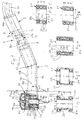
- FIG. 1 in its entirety designated 1 treatment instrument consists of a rear instrument part, namely a so-called connector part 2, and a front instrument part, namely the so-called handpiece 3, which are releasably connected to each other by a plug-in coupling 4, in particular a plug / turn coupling.
- a holding device 5 is arranged for a tool 6 at the front end of the treatment instrument 1, wherein the tool 6 can protrude laterally or forwards.
- the handpiece 3 may be straight or curved towards the tool 6 side facing away or extend angularly.
- the plug-in / rotary coupling is formed by a circular cross-section coupling recess 7 and a therein plugged in with little play coupling pin 8.
- the coupling recess 7 is arranged at the rear end of the handpiece 3, and the substantially cylindrical coupling pin 8 extends from the connection part 2 to the front.
- a latching device 9 This has a latching element 9a, which is mounted radially movably in the one coupling part and is biased by a spring force into a latching position passing through the dividing joint, in which the latching element 9a engages in an annular groove in the other coupling part.
- a latching device 9 can be over pushed by a manual axial Anlagenkraftausübung, wherein the latching element 9a is automatically displaced into its release position.
- the connector 2 is connected to a flexible supply line 2a, which is connected to a control unit, not shown.
- the handpiece 3 is preferably freely rotatably mounted on the coupling pin 8, whereby the handling is improved.
- plug / twist coupling 4 extends at least one media line 10 for a treatment or drive medium, for.
- the media line 10 may extend axially (not shown) or Z-shaped by a radial (not shown) or hollow cylindrical pitch between the coupling recess 7 and the coupling pin 8, wherein the media line 10, the dividing joint in the region of an annular groove in the coupling pin 8 or in the Coupling recess 7 passes through, so that is guaranteed in each rotational position of the media passage.
- the media line 10 extends from the rear end of the treatment instrument 1 to its front end portion, where it may extend partially as a channel in the instrument body or as a hose or pipe.
- the media line 10 opens in the front end region of the treatment instrument 1 from this, said mouth opening 10a is directed to the treatment site or on the tip of the tool 6.
- the handpiece 3 has a rotatably mounted therein in a rolling bearing rotary member 12.
- a rolling bearing rotary member 12 This may be a one-piece design or consist of a rear or front shaft portion 13a, 13b, which are firmly connected to each other at the apex of the angle.
- a turbine At the front end of the shaft 13 is a thickened head 14, in which a turbine is arranged with a turbine wheel 15 which is rotatable about a transversely to the shaft 13 and to its longitudinal central axis 13 c and in the angular plane of the shaft 13 extending axis of rotation 16 in the Head 14 is stored.
- the turbine wheel 15 is located in a turbine chamber 17, into which a media line 10b for compressed air opens and is directed onto the blades of the turbine wheel 15.
- the turbine wheel 15 is connected to the holding device 5, here with a receiving sleeve 18, in which the tool 6 with its shaft can be inserted and releasably fixed in a conventional manner by a fixing device.
- the turbine wheel and the receiving sleeve 18 may be integrally formed.
- the turbine wheel 15 is connected to the end of the receiving sleeve 18 facing away from the plug-in opening 18a.
- existing turbine rotor 15a is a double-row roller bearing 21 arranged in two rows rolling elements 22, z.
- the hollow cylindrical outer bearing sleeve 23 is seated in a transverse bore 24 in the head 14 and the hollow cylindrical inner bearing sleeve 25 is seated on the receiving sleeve 18. It is a with respect to the turbine 15 on one side and tool side arranged rotary bearing. On the side of the turbine wheel 15 facing away from the tool side, the turbine rotor 15a is not supported.
- the bearing sleeves 23, 25 have on their inner or outer lateral surface in each case in the corresponding transverse plane of the series of grooves 22a, in which the rolling elements 22 can rotate. Between the turbine chamber 17 and the transverse bore 24, a ring seal is provided for sealing the rolling bearing 21, not for reasons of simplicity is shown.
- the turbine chamber 17 is covered by a radial head wall 14a.
- This head wall 14a may be a special component, which is connected in the form of a housing 14b to the head housing surrounding the turbine chamber 17 and the transverse bore 24, for example by means of a housing 14b.
- B. is screwed.
- the shank of the tool 6 located in the receiving sleeve 18 can be detachable from the side of the head 14 facing away from the tool side through a coaxial hole with a release pin 26 arranged on this head side.
- the release pin 26 is slidably mounted between an ejected ready position and an inserted Lexcellentend ein along the axis of rotation 16 and by a z.
- Such a release device is known per se.
- the embodiments of the rolling bearing 11 after the Fig. 2 to 4 differ from the above-described embodiment in that either the outer bearing sleeve ( Fig. 2 ) or the inner bearing sleeve ( Fig. 3 ) each consist of two successively arranged outer bearing sleeve parts 23a, 23b or inner bearing sleeve parts 25a, 25b, wherein the bearing sleeve parts can have an axial distance from each other or as it Fig. 4 for an inner bearing sleeve 25 shows, can lie against each other.
- the grooves 22a each open to the common dividing joint 25c, as in Fig. 4 hinted at with dashed lines.
- a common dividing joint and / or axially extending grooves may also be arranged symmetrically in the outer bearing sleeve 23.
- the respective outer or inner bearing sleeve parts can be mounted by an axial movement and each completed to the rolling bearing 21.
- the bearing sleeve parts 23a, 23b 25a, 25b can be mounted in mutually identical orientation or rotated by 180 ° positions.
- the inner flange 23c extending radially inwardly from the outer bearing sleeve 23 is disposed between the rows, and the outer flange 25c extending radially outward from the inner bearing sleeve 25 is disposed axially outward of the row concerned.
- the outer flange 25c is arranged between the rows and the inner flange 23c is arranged axially outside of the relevant row, as it Fig. 6 shows.
- the rolling elements 22 and the associated rolling grooves 22b in the end face of the shorter outer or inner bearing sleeve 23, 25 and the axially opposite flange 23c, 25c. That is, only one flange 23c or 25c needs to be present at a time.
- Such a rolling bearing 21 is a radial bearing with respect to a row of rolling bearings and a thrust bearing with respect to the other row of rolling bearings. Therefore, the rolling bearing 21 can accommodate both radial and axial bearing forces in this embodiment. It is therefore particularly suitable for the storage of a receiving sleeve 18 in the head 14, which is charged in functional operation not only by resulting from the resistance forces of the tool 6 radial forces, but also axial forces during operation.
- Fig. 7 is a rolling bearing 21 of the embodiment according to Fig. 5 arranged on the side facing away from the tool side of the turbine wheel 15 for supporting the receiving sleeve 18.
- this bearing arrangement is particularly advantageous.
- the rolling bearing 21 after Fig. 5 or 6 in a receiving sleeve 18 according to Fig. 1 to arrange on the tool side of the turbine wheel 15, z. B. in combination with a single-row roller bearing on the side facing away from the tool side of the turbine wheel 15 at a receiving sleeve 18 according to Fig. 7 can be arranged.
- another tool release device not shown, is provided.
- the rolling bearing 21 is arranged in the shaft 13 for pivotal mounting of a rotatably mounted therein rotary member 12, here for pivotal mounting of a drive shaft longitudinal section.
- a drive motor (not shown) arranged in the dash-dotted complemented connector 2 and drivingly connected by a drive shaft train 33 with a plurality of drive shaft sections with the receiving sleeve 18.
- the drive shaft train 33 has a plug-in coupling 32 with two plug-in coupling elements 32a, 32b which correspond to one another in a form-fitting manner on, whereby the coupling and decoupling of the plug-in coupling 4 at the same time a coupling and decoupling of the plug-in coupling 32 is possible.
- a drive shaft section 33a arranged in the rear end region of the handpiece 3 extends into the apex region of the angled shaft 13, its front end being drivingly connected to a third drive shaft section 33c by a second drive shaft section 33b extending axially only in the apex region front shank portion 13b extends to the receiving sleeve 18 and is drivingly connected thereto.
- a gear transmission is provided in each case.
- a gear 34 is disposed with an internal toothing, which meshes with a pinion 35 at the rear end of the second drive shaft section 33b.
- the second drive shaft section 33b is arranged offset to the side facing away from the tool 6 in the apex region, wherein at the front end of the second drive shaft section 33b and at the rear end of the third drive shaft section 33c each have a pinion 36, 37 substantially in a transverse plane or overlapping each other are, in the sense of spur gears combing each other.
- the second and third drive shaft sections 33b, 33c enter an obtuse angle W1, which is open towards the side facing away from the tool 6.
- the drive connection between the third drive shaft section 33 c and the receiving sleeve 18 is formed by a bevel gear with a bevel gear 38 at the front end of the third drive shaft section 33 c and bevel gear 39 on the receiving sleeve 18.
- the tooth engagement between the bevel gears 38, 39 is arranged with respect to the third drive shaft section 33 c on its side facing away from the tool 6. As a result, the receiving sleeve 18 is driven in the same direction of rotation as the first drive shaft section 33a.
- the receiving sleeve 18 is rotatably supported by two roller bearings 41, 42 in the head 14, which have a longitudinal axis of rotation 16 directed distance from each other, which is larger than the bevel gear 38, so that the latter can be arranged therebetween, including the bevel gear 39, the side facing away from the tool 6 of the conical edge 38 and at the same time on the tool 6 facing side of the rolling bearing 41 is disposed further away from the tool 6 than the other rolling bearing 42.
- a roller bearing 33, 44 arranged on the end regions of this drive shaft section 33c, the outer rings are seated in a longitudinal hole, not shown, of the shaft portion 13b.
- the design of the gear wheel 34 as a ring gear allows a relatively large translation of the rotational speed between the first and the second drive shaft section 33a, 33b in a radially smaller construction.
- a double-row rolling bearing 21a, 21b is provided in the shaft 13.
- This rolling bearing 21a, 21b is in each case sufficient to store the entire drive shaft section 33a or 33b sufficiently stable.
- the first drive shaft portion 33a projects beyond the rolling bearing 21a to the rear freely projecting, whereby a slight radial flexibility for coupling with the drive shaft portion of the connecting part 2 is present.
- a hinge joint 28 may be connected to a transverse pin 29, whereby the radial flexibility of the first drive shaft portion 33a is increased.
- the gear 34 consists of a rear cylindrical or hollow cylindrical bearing portion 34a, at the front end of a flange 34b is arranged, which carries on its front side the ring gear.
- the rolling bearings 21a, 21b of the embodiment according to Fig. 3 are arranged, which carries on its front side the ring gear.
- the distance a of the rows of rolling elements can be dimensioned from each other preferably larger than the average diameter b of the WälzSystemterrorismrillen 22a.
- the rolling bearing 21b is dimensioned so long, see L, that it fits between the groove 35, 36, whereby at the same time an axial boundary for the second drive shaft portion 32b is formed.
- the distance a may also be smaller than the average groove diameter b, since only one row of rolling elements is effective radially.
- Both rolling bearings 21a, 21 are preferably mounted in a common support body 44 which sits in the vertex area adjacent the rear shaft portion 13a in the shaft 13 and is removable by a back or forward ausmündendes receiving hole from the rear and back again or vice versa axially fixable in a manner not shown.
- the rear roller bearing 21a is inserted into a receiving hole 45a of the support body 45 from the rear and z. B. axially fixed by a arranged at the rear end of the outer bearing sleeve 23 flange 23d forward.
- the front roller bearing 21b is inserted from the front into a receiving hole 46 of the support body 45 and axially fixed.
- the flange 34 is in the receiving hole 45a is supported between the rolling bearing 21a and the bottom of the receiving hole 45a with play.
- this handpiece 3 denotes a light-conducting rod, which extends in the vicinity of the edge of the shaft 13 in this exit window 48 directed from the rear to the front on the free end of the tool 6.
- light from a light source is coupled into the Lichtleitstab 47, wherein the light source 47a on a rotatably mounted in the connection part 2 carousel 49 (hinted) is arranged, so that in this case, the free rotation of the handpiece 3 in the Plug / rotary coupling 4 is guaranteed.
- the in Fig. 8 between the central axis of the front shaft portion 13b and the rotation axis 16 of the receiving sleeve 18 included angle W2 is substantially 100 °.
- Such a configuration is particularly favorable taking into account the anatomy in the mouth of a patient.
- This favorable embodiment with the angle W2 equal to 100 ° applies not only for the operable with a motor in the connection part 2 handpiece 3 according to Fig. 8 , but also for the turbine handpiece 3 according to Fig. 1 and the still to be described, operable with a motor in the connection part 2 handpiece 3 according to Fig. 9 even if the latter are shown with an angle W3 between the shaft portion 13b and the rotation axis 16 of about 90 °.
- An angle between 90 and preferably 100 ° is favorable.
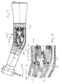
- the handpiece 3 according to the embodiment according to Fig. 9 differs from the embodiment according to Fig. 8 by two main features.
- the second and third drive shaft sections 33b, 33c are non-overlapping, but their facing ends are axially adjacent each other, enclosing an obtuse angle W4 that is less than the angle W 1 and about 135 to 150 degrees.
- the gears 36, 37 thus mesh with each other in the sense of a true angular gear with forward or backward teeth, which are respectively arranged on the side facing away from the tool 6 of the circumference. Therefore, the rotational direction of the second and third drive shaft section 33b, 33c is not in the opposite direction, as in the embodiment according to Fig. 8 but in the same direction.
- the second drive shaft portion 33b with respect to the first drive shaft portion 33a is not arranged axially parallel, but it includes an acute angle W5 of about 10 to 20 ° with this.
- the second drive shaft section 33b is arranged with the rolling bearing 21b in a hollow cylindrical mounting sleeve 51, which can be inserted from the front into the bearing body 44, in particular screwed and with the preferably integrally formed on the second drive shaft portion 33b pinion 35, the gear 36 and the rolling bearing 21b forms a prefabricated unit.
- the rear end of the third drive shaft portion 33c may be mounted with the rolling bearing 43 in a bearing bush 53 which projects integrally from the rear shaft portion 13a in the front shaft portion 13b and in the transition region an enlarged clearance 44 for the gear 36 and for the installation sleeve 52 has.
- the exemplary embodiment follows Fig. 9 the drive connection between the bevel gears 38, 39 is not arranged on the side facing away from the tool 6, but on the side facing the tool 6 of the bevel gear 38, wherein the bevel gear 39 with respect to the bevel gear 38 on the tool 6 facing side on the receiving sleeve 18 is.
- the direction of rotation of the receiving sleeve 18 vice versa, wherein the above-described rotation reversal on the gear transmission 35, 37 is compensated and thus the directions of rotation of the receiving sleeves 18 in the embodiment according to Fig. 8 and 9 are the same again.
- the receiving sleeve 18 is mounted in the head 14 in a double-row roller bearing 21c, which also according to the embodiment Fig. 3 corresponds, that has a continuous outer bearing sleeve 23.
- the bevel gear 39 may be with a hollow cylindrical section carrier of the associated bottom bracket shell portion 25b.
- an additional release pin 26b for spreading a arranged in the receiving sleeve 18 clamping sleeve 55 is axially displaceable and manually by the release pin 26a of the tool 6 side facing away actuated.
- the tool 6 remote from the end portion of the outer bearing sleeve 23 may be stored in the screw socket 14c of the head wall 14b having head housing cover 14c, as it Fig. 11 shows.
- the rolling bearing 21 c is thus also mounted and dismountable from the side facing away from the tool 6.
- the z. B. may be formed by a cam 56 which engages in a recess 57.
- the cam 56 is arranged in the end region facing away from the tool on the circumference of the outer bearing sleeve 23 and he summarizes in an axial groove in the wall of the Outside bearing sleeve 23 receiving bearing bore.
- the rotary member 12 is thus formed by the receiving sleeve 18.
- the rolling elements 22 associated cages between the outer bearing sleeve 23 and the inner bearing sleeve 25 and the sleeve parts 23a, 23b, 25a, 25b are provided.
Abstract
Description
Die Erfindung bezieht sich auf ein medizinisches oder dentalmedizinisches Handstück oder auf ein Wälzlager für ein solches Handstück nach dem Oberbegriff des Anspruches 1 oder 8.The invention relates to a medical or dental handpiece or to a rolling bearing for such a handpiece according to the preamble of
Bei einem vorliegenden Handstück handelt es sich um einen länglichen bzw. stabförmigen Gegenstand, das in seinem vorderen Endbereich ein Werkzeug zur Behandlung des menschlichen oder tierischen Körpers oder eines Modells (Prothese) davon aufweist oder mit einem solchen Werkzeug verbindbar ist und an seinem hinteren Ende mit einer sog. flexiblen Versorgungsleitung verbunden oder durch eine Kupplung verbindbar ist. Durch die Versorgungsleitung ist bzw. sind dem Handstück Antriebsenergie für einen Antriebsmotor und/oder Versorgungsenergie, z.B. für eine Beleuchtungseinrichtung, und/oder Behandlungsmedien zuführbar.A present handpiece is an elongate or rod-shaped object which has in its front end region a tool for treating the human or animal body or a model (prosthesis) thereof or can be connected to such a tool and at its rear end a so-called flexible supply line connected or connectable by a coupling. Through the supply line, drive power to a drive motor and / or supply energy, e.g. for a lighting device, and / or treatment media fed.
Handstücke der vorliegenden Art gibt es in unterschiedlichen Ausgestaltungen bezüglich der Formgebung und Konstruktion, der Werkzeugart und - bewegung und/oder der Antriebsart. Es gibt Handstücke in Form eines sich gerade oder abgewinkelt erstreckenden Griffteils. Bei dem Werkzeug handelt es sich z.B. um ein Rotationswerkzeug oder um ein hin und her bewegbares Werkzeug. Als Antrieb kann dem Handstück ein mechanischer Antrieb mit einer drehbar gelagerten Antriebswelle oder ein pneumatischer Antrieb mit einer vorzugsweise im vorderen Handstückbereich angeordneten Turbine ausgebildet sein, zu der sich von hinten nach vorne eine Druckluftleitung erstreckt.Handpieces of the present type are available in different configurations with respect to the design and construction, the type of tool and - movement and / or the drive. There are handpieces in the form of a straight or angled extending grip part. The tool is e.g. a rotary tool or a reciprocating tool. As a drive, the handpiece, a mechanical drive with a rotatably mounted drive shaft or a pneumatic drive may be formed with a preferably arranged in the front handpiece area turbine to which extends from back to front a compressed air line.
Ein vorliegendes Handstück kann somit in jedem Bereich seiner Länge ein drehbar gelagertes Drehteil aufweisen, das für hochtourigen bis niedrigtourigen Funktionsbetrieb ausgebildet sein kann. Ein hochtouriger Funktionsbetrieb wird in den meisten Fällen für ein Werkzeug zur spanabhebenden Bearbeitung, z.B. zur Entfernung von Karies, verwendet. Es gibt jedoch auch Handstücke mit einem Werkzeug, das mit geringer Drehzahl angetrieben wird, z.B. bei solchen Werkzeugen die im Funktionsbetrieb eine Schraubarbeit ausführen, wie es bei der Implantologie zum Setzen und Entfernen von Implantaten der Fall ist.A present handpiece can thus have a rotatably mounted rotary part in each region of its length, which can be designed for high-speed to low-speed functional operation. High speed functional operation is in most cases used for a machining tool, e.g. for removing caries. However, there are also handpieces with a tool driven at low speed, e.g. in the case of such tools, which perform a screwing operation during functional operation, as is the case with implantology for the placement and removal of implants.
Ein Wölzlager nach dem Oberbegriff des Anspruchs 1 ist in der
Ein Handstück nach dem Oberbegriff des Anspruches 8 ist z.B. in der
An ein Handstück der vorliegenden Art sind mehrere Forderungen gestellt. Insbesondere bei einem Handstück für oder mit einem Werkzeug, das im Funktionsbetrieb hochtourig dreht, ist bezüglich des verursachten Geräusches verbesserungsbedürftig, da ein geräuschvoller Betrieb den zu behandelnden Patienten stört. Dies gilt insbesondere für Handstücke, die im Kopfbereich des Patienten benutzt werden, wie es bei dentalmedizinischen Handstücken der Fall ist.To a handpiece of the present type, several demands are made. In particular, in a handpiece for or with a tool that rotates in high-speed functional operation, with respect to the noise caused is in need of improvement, since a noisy operation disturbs the patient to be treated. This is especially true for handpieces that are used in the head area of the patient, as is the case with dental handpieces.
Um zum einen eine handgerechte Baugröße zu erreichen, die zum anderen auch in kleinen Körperhöhlen einsetzbar ist, soll ein vorliegendes Handstück auch von kleiner Bauweise sein, was auch das Drehteil sowie dessen Lagerteile betrifft. Hierbei ist auch zu berücksichtigen, daß bei Gewährleistung der kleinen Bauweise eine einfache und schnell durchführbare Montage bzw. Demontage möglich sein soll.In order to achieve a hand-sized size on the one hand, on the other hand can be used in small body cavities, an existing handpiece should also be of small construction, which also affects the rotary part and its bearing parts. It should also be borne in mind that, while ensuring the small construction, a simple and quick to carry out assembly or disassembly should be possible.
Zum anderen soll das Handstück zur Verbesserung seiner Marktchancen von kostengünstiger Bauweise sein.On the other hand, the handpiece should be to improve its market opportunities of cost-effective design.
Der Erfindung liegt die Aufgabe zugrunde, ein Handstück oder ein Wälzlager nach dem Oberbegriff des Anspruches 1 oder 8 bezüglich der vorbeschriebenen Forderungen zu verbessern.The invention has for its object to improve a handpiece or rolling bearing according to the preamble of
Diese Aufgabe wird durch die Merkmale des Anspruches 1 oder 8 gelöst. Vorteilhafte Weiterbildungen der Erfindung sind in zugehörigen Unteransprüchen beschrieben.This object is solved by the features of
Bei der erfindungsgemäßen Ausgestaltung weist das Handstück mindestens ein zur Lagerung des Drehteils bestimmtes Wälzlager, insbesondere Miniaturwälzlager, mit mindestens zwei nebeneinander angeordneten Wälzkörperreihen auf. Hierbei erstreckt sich der Innenring und/oder der Außenring jeweils axial über beide Wälzlagerreihen. Hierdurch werden mehrere Vorteile erzielt. Zum einen ist das Wälzlager durch das oder die sich über beide Wälzlagerreihen erstreckende Lagerhülse stabilisiert. Dies führt zu einer geringeren Belastung des Wälzlagers und zu einem ruhigen Rotationsbetrieb langer Lebensdauer. Dabei ist auch festgestellt worden, daß die im Funktionsbetrieb entstehenden Laufgeräusche gemindert werden, was insbesondere für hochtourige Wälzlager bzw. Drehteile bedeutungsvoll ist. Eine erfindungsgemäße Ausgestaltung führt auch zu geringen Herstellungskosten, da das erfindungsgemäße Wälzlager zwei Einzel-Wälzlager ersetzen kann und aufgrund der Bauweise mit einer gemeinsamen Innen- und/oder Außenlagerhülse zwei Teile zu einem gemeinsamen Teil miteinander verbunden sind und deshalb dies gemeinsame Teil kostengünstiger herstellbar ist. Die Verbindung zu einem gemeinsamen Teil bzw. zu einer gemeinsamen Baueinheit ermöglicht auch eine einfache und schnelle Montage, da weniger Bauteile zu handhaben sind.In the embodiment according to the invention, the handpiece has at least one roller bearing intended for supporting the rotary part, in particular miniature rolling bearings, with at least two rolling element rows arranged next to one another. Here, the inner ring and / or the outer ring extends axially over both rows of rolling bearings. As a result, several advantages are achieved. On the one hand, the rolling bearing is stabilized by the bearing or the bearing sleeve extending over both rows of rolling bearings. This leads to a lower load of the rolling bearing and a quiet rotation operation long life. It has also been found that the operating noise resulting from operation are reduced, which is particularly significant for high-speed bearings and rotating parts. An embodiment of the invention also leads to low production costs, since the rolling bearing according to the invention can replace two single bearings and due to the construction with a common inner and / or outer bearing sleeve two parts to a common part with each other are connected and therefore this common part is cheaper to produce. The connection to a common part or to a common structural unit also enables a simple and quick assembly, since fewer components have to be handled.
Ein vorliegendes Wälzlager hat im Funktionsbetrieb nicht nur radiale Belastungskräfte, sondern auch axiale Belastungskräfte aufzunehmen, die verstärkt dann auftreten können, wenn das Werkzeug im Funktionsbetrieb axialen Belastungen ausgesetzt ist.A present rolling bearing has to accommodate not only radial load forces, but also axial loading forces in functional operation, which can occur increasingly when the tool is exposed to axial loads during operation.
Der Erfindung liegt deshalb im weiteren die Aufgabe zugrunde, ein Wälzlager nach dem Oberbegriff des Anspruchs 1 bezüglich seiner Eignung, auch axiale Belastungskräfte aufzunehmen, zu verbessern.The invention is therefore the further object of a rolling bearing according to the preamble of
Diese Aufgabe wird durch die Merkmale des Anspruchs 1 gelöst. Vorteilhafte Weiterbildungen der Erfindung sind in den zugehörigen Unteransprüchen beschrieben.This object is solved by the features of
Beim erfindungsgemäßen Wälzlager nach Anspruch 1 kann eine Wälzkörperreihe axiale Belastungskräfte aufnehmen. Deshalb kann das erfindungsgemäße Wälzlager für sowohl radiale als auch axiale Belastungsfälle eingesetzt werden. Hierbei ist als weiterer Vorteil anzusehen, daß ein Radiallager und ein Axiallager in eine Wälzlagereinheit integriert sind, wobei Herstellungskosten, Baugrößen, Lagerkapazitäten und der Aufwand bei der Montage bzw. Demontage verringert werden können.In the rolling bearing according to the invention according to
Diese Verbesserung läßt sich bei einfacher und preiswerter Bauweise des Wälzlagers verwirklichen, wodurch auch die Wettbewerbsfähigkeit des Wälzlagers und des Handstücks verbessert wird.This improvement can be realized in a simple and inexpensive construction of the bearing, whereby the competitiveness of the bearing and the handpiece is improved.
Bei einem Handstück, in dem ein Antriebswellenzug für den Antrieb des Werkzeugs drehbar gelagert ist, ergeben sich im vorderen Endbereich einer sich quer zur Längsachse des Handstücks erstreckenden Werkzeugaufnahme und/oder im Scheitelbereich eines abgewinkelten Handstücks unter Berücksichtigung gewünschter Drehzahlen und/oder der Drehrichtungen besondere Anforderungen.In a handpiece in which a drive shaft train is rotatably mounted for driving the tool, special requirements arise in the front end region of a tool holder extending transversely to the longitudinal axis of the handpiece and / or in the apex region of an angled handpiece, taking into account desired rotational speeds and / or directions of rotation ,
Der Erfindung liegt deshalb im weiteren die Aufgabe zugrunde, ein Handstück der im Oberbegriff des Anspruches 8 angegebenen Art hinsichtlich der in Antriebsverbindung miteinander stehenden Antriebswellenabschnitte zu verbessern.The invention is therefore based on the further object of improving a handpiece specified in the preamble of claim 8 type with respect to each other in driving connection drive shaft sections.
Diese Aufgabe wird durch die Merkmale des Anspruches 8 gelöst. Vorteilhafte Weiterbildungen der Erfindung sind in zugehörigen Unteransprüchen beschrieben.This object is solved by the features of claim 8. Advantageous developments of the invention are described in the appended subclaims.
Bei der erfindungsgemäßen Ausgestaltung nach Anspruch 8 weist das Handstück einen weiteren, nämlich einen mittleren Antriebswellenabschnitt auf, der es ermöglicht, die Drehrichtung des vorderen Antriebswellenabschnitts umzukehren und/oder Drehzahlübersetzungen oder Drehzahluntersetzungen zu verwirklichen. Hierdurch läßt sich das Handstück so verändern, daß es spezielle oder einen größeren Bereich von Anforderungen erfüllen kann und deshalb der Einsatzbereich des Handstücks vergrößert ist.In the embodiment according to the invention according to claim 8, the handpiece on another, namely a central drive shaft portion, which makes it possible to reverse the direction of rotation of the front drive shaft portion and / or to realize speed ratios or speed reductions. In this way, the handpiece can be changed so that it can meet special or a wider range of requirements and therefore the range of use of the handpiece is increased.
In den Unteransprüchen sind Merkmale enthalten, die im weiteren zu einer kleinen, kostengünstig herstellbaren, stabilen, vorteilhaft integrierbaren und stabilisierenden Bauweise sichere Funktionen und lange Lebensdauer beitragen.In the dependent claims are included features that contribute to a small, inexpensive to produce, stable, advantageous integrable and stabilizing construction safe functions and long life.
Nachfolgend werden vorteilhafte Ausgestaltungen der Erfindung anhand von Zeichnungen näher erläutert. Er zeigt:
- Fig. 1
- ein erfindungsgemäßes Handstück mit einem Drehteil, das in einem Wälzlager gelagert ist, in der Seitenansicht, teilweise geschnitten;
- Fig. 2
- ein Wälzlager in abgewandelter Ausgestaltung als Einzelteil im axialen Schnitt;
- Fig. 3
- ein Wälzlager im axialen Schnitt in abgewandelter Ausgestaltung;
- Fig. 4
- ein Wälzlager im axialen Schnitt in weiter abgewandelter Ausgestaltung;
- Fig. 5
- ein erfindungsgemäßes Wälzlager im axialen Schnitt in weiter abgewandelter Ausgestaltung;
- Fig. 6
- ein erfindungsgemäßes Wälzlager im axialen Schnitt in weiter abgewandelter Ausgestaltung;
- Fig. 7
- den vorderen Endbereich des Handstücks im axialen Schnitt in weiter abgewandelter Ausgestaltung;
- Fig. 8
- ein erfindungsgemäßes Handstück im axialen Schnitt in weiter abgewandelter Ausgestaltung;
- Fig. 9
- ein erfindungsgemäßes Handstück im axialen Schnitt in weiter abgewandelter Ausgestaltung;
- Fig. 10
- die in
Fig. 9 mit X gekennzeichnete Einzelheit in vergrößerter Darstellung; - Fig. 11
- den vorderen Endbereich des Handstücks nach
Fig. 9 im axialen Schnitt und in vergrößerter Darstellung.
- Fig. 1
- an inventive handpiece with a rotary member which is mounted in a rolling bearing, in side view, partially cut;
- Fig. 2
- a rolling bearing in a modified embodiment as a single part in axial section;
- Fig. 3
- a rolling bearing in axial section in a modified embodiment;
- Fig. 4
- a rolling bearing in axial section in a further modified embodiment;
- Fig. 5
- an inventive rolling bearing in axial section in a further modified embodiment;
- Fig. 6
- an inventive rolling bearing in axial section in a further modified embodiment;
- Fig. 7
- the front end portion of the handpiece in axial section in a further modified embodiment;
- Fig. 8
- an inventive handpiece in axial section in a further modified embodiment;
- Fig. 9
- an inventive handpiece in axial section in a further modified embodiment;
- Fig. 10
- in the
Fig. 9 with X marked detail in an enlarged view; - Fig. 11
- the front end of the handpiece
Fig. 9 in axial section and in an enlarged view.
Das in
Das Anschlußteil 2 ist mit einer flexiblen Versorgungsleitung 2a verbunden, die mit einem nicht dargestellten Steuergerät verbunden ist. Das Handstück 3 ist vorzugsweise auf dem Kupplungszapfen 8 frei drehbar gelagert, wodurch die Handhabbarkeit verbessert wird. Durch die Steck/Dreh-Kupplung 4 erstreckt sich wenigstens eine Medienleitung 10 für ein Behandlungs- oder Antriebsmedium, z. B. Wasser, Druckluft oder ein Wasser/Luft-Gemisch (Spray). Die Medienleitung 10 kann sich axial (nicht dargestellt) oder Z-förmig durch eine radiale (nicht dargestellt) oder hohlzylindrische Teilungsfuge zwischen der Kupplungsausnehmung 7 und dem Kupplungszapfen 8 erstrecken, wobei die Medienleitung 10 die Teilungsfuge im Bereich einer Ringnut im Kupplungszapfen 8 oder in der Kupplungsausnehmung 7 durchsetzt, so daß in jeder Drehstellung der Mediendurchgang gewährleistet ist. Beiderseits vom Durchgang ist die Teilungsfuge durch einen Dichtring 8a abgedichtet, der in einer Ringnut in der Wandung der Kupplungsausnehmung 7 oder in der Mantelfläche des Kupplungszapfens 8 angeordnet sein kann. Hierdurch ist eine freie Drehbarkeit um 360 ° und mehr gewährleistet. Die Medienleitung 10 erstreckt sich vom hinteren Ende des Behandlungsinstruments 1 zu dessen vorderem Endbereich, wobei sie teilweise als Kanal im Instrumentenkörper oder als Schlauch- bzw. Rohrleitung verlaufen kann. Die Medienleitung 10 mündet im vorderen Endbereich des Behandlungsinstruments 1 aus diesem aus, wobei diese Mündungsöffnung 10a auf die Behandlungsstelle bzw. auf die Spitze des Werkzeugs 6 gerichtet ist.The
Bei allen Ausführungsbeispielen der Erfindung, bei denen gleiche oder vergleichbare Teile mit gleichen Bezugszeichen versehen sind, weist das Handstück 3 ein darin in einem Wälzlager drehbar gelagertes Drehteil 12 auf. Beim Ausführungsbeispiel nach
Die Ausführungsbeispiele des Wälzlagers 11 nach den
Beim Ausführungsbeispiel nach
Ein solches Wälzlager 21 ist bezüglich einer Wälzlagerreihe ein Radiallager und bezüglich der anderen Wälzlagerreihe ein Axiallager. Deshalb kann das Wälzlager 21 bei dieser Ausgestaltung sowohl radiale als auch axiale Lagerkräfte aufnehmen. Es eignet sich deshalb besonders zur Lagerung einer Aufnahmehülse 18 im Kopf 14, die im Funktionsbetrieb nicht nur durch aus den Widerstandskräften des Werkzeugs 6 resultierenden Radialkräften, sondern auch Axialkräften im Funktionsbetrieb belastet wird.Such a rolling
Beim Ausführungsbeispiel nach
Beim Ausführungsbeispiel nach
Ein im hinteren Endbereich des Handstücks 3 angeordneter Antriebswellenabschnitt 33a erstreckt sich bis in den Scheitelbereich des abgewinkelten Schaftes 13, wobei sein vorderes Ende durch einen sich im wesentlichen nur im Scheitelbereich axial erstreckenden zweiten Antriebswellenabschnitt 33b antriebsmäßig mit einem dritten Antriebswellenabschnitt 33c verbunden ist, der sich im vorderen Schaftabschnitt 13b bis zur Aufnahmehülse 18 erstreckt und antriebsmäßig mit dieser verbunden ist. Zur Verbindung der Antriebswellenabschnitte 33a, 33b, 33c ist jeweils ein Zahnradgetriebe vorgesehen. Am vorderen Ende des ersten Antriebswellenabschnitts 33a ist ein Zahnrad 34 mit einer Innenverzahnung angeordnet, die mit einem Ritzel 35 am hinteren Ende des zweiten Antriebswellenabschnitts 33b kämmt. Dabei ist der zweite Antriebswellenabschnitt 33b zur dem Werkzeug 6 abgewandten Seite hin versetzt im Scheitelbereich angeordnet, wobei am vorderen Ende des zweiten Antriebswellenabschnitts 33b und am hinteren Ende des dritten Antriebswellenabschnitts 33c jeweils ein Ritzel 36, 37 im wesentlichen in einer Querebene bzw. einander überlappend angeordnet sind, im Sinne von Stirnrädern die miteinander kämmen. Der zweite und der dritte Antriebswellenabschnitt 33b, 33c einen stumpfen Winkel W1 ein, der zur dem Werkzeug 6 abgewandten Seite hin offen ist.A
Die Antriebsverbindung zwischen dem dritten Antriebswellenabschnitt 33c und der Aufnahmehülse 18 ist durch ein Winkelzahnradgetriebe mit einem Kegelzahnrad 38 am vorderen Ende des dritten Antriebswellenabschnitts 33c und Kegelzahnrad 39 auf der Aufnahmehülse 18 gebildet. Der Zahneingriff zwischen dem Kegelzahnrädern 38, 39 ist bezüglich des dritten Antriebswellenabschnitts 33c auf dessen dem Werkzeug 6 abgewandten Seite angeordnet. Hierdurch wird die Aufnahmehülse 18 in der gleichen Drehrichtung angetrieben, wie der erste Antriebswellenabschnitt 33a. Die Aufnahmehülse 18 ist mittels zwei Wälzlagern 41, 42 im Kopf 14 drehbar gelagert, die einen längs der Drehachse 16 gerichteten Abstand voneinander aufweisen, der größer ist als das Kegelzahnrad 38, so daß letzteres dazwischen angeordnet werden kann, einschließlich dem Kegelrad 39, das auf der dem Werkzeug 6 abgewandten Seite des Kegelrandes 38 und zugleich auf der dem Werkzeug 6 zugewandten Seite des Wälzlagers 41 angeordnet ist, das vom Werkzeug 6 weiter entfernt angeordnet ist als das andere Wälzlager 42. Zur Drehlagerung des zweiten Antriebswellenabschnitts 33c ist jeweils ein Wälzlager 33, 44 auf den Endbereichen dieses Antriebswellenabschnitts 33c angeordnet, deren Außenringe in einem nicht dargestellten Längsloch des Schaftabschnitts 13b sitzen.The drive connection between the third
Die Ausgestaltung des Zahnrads 34 als Hohlrad ermöglicht bei radial kleiner Bauweise eine verhältnismäßig große Übersetzung der Drehzahl zwischen dem ersten und dem zweiten Antriebswellenabschnitt 33a, 33b.The design of the
Beim Ausführungsbeispiel nach
Bei allen Wälzlagern 21, 21a, 21b kann der Abstand a der Wälzkörperreihen voneinander vorzugsweise größer bemessen, als der mittlere Durchmesser b der Wälzkörperlaufrillen 22a. Das Wälzlager 21b ist so lang bemessen, siehe L, daß es zwischen die Ritze 35, 36 paßt, wodurch zugleich eine axiale Begrenzung für den zweiten Antriebswellenabschnitt 32b gebildet ist. Bei den Ausführungsbeispielen nach
Beide Wälzlager 21a, 21 sind vorzugsweise in einem gemeinsamen Tragkörper 44 gelagert, der im der Scheitelstelle benachbarten Bereich des hinteren Schaftabschnitts 13a im Schaft 13 sitzt und durch ein nach hinten oder nach vorne ausmündendes Aufnahmeloch von hinten montierbar und nach hinten wieder demontierbar ist oder umgekehrt sowie in nicht dargestellter Weise axial fixierbar ist.Both rolling
Wie sich aus
Mit 47 ist ein Lichtleitstab bezeichnet, der in Randnähe des Schaftes 13 in diesem von hinten nach vorne auf das freie Ende des Werkzeug 6 gerichteten Austrittsfenster 48 erstreckt. Im Funktionsbetrieb dieses Handstücks 3 wird Licht von einer Lichtquelle in den Lichtleitstab 47 eingekoppelt, wobei die Lichtquelle 47a auf einem im Anschlußteil 2 drehbar gelagerten Karussell 49 (andeutungsweise dargestellt) angeordnet ist, so daß auch in diesem Falle die freie Drehbarkeit des Handstücks 3 in der Steck/Drehkupplung 4 gewährleistet ist.47 denotes a light-conducting rod, which extends in the vicinity of the edge of the
Der in
Das Handstück 3 nach dem Ausführungsbeispiel gemäß
Im Unterschied zum Ausführungsbeispiel nach
Wie
Zum anderen ist beim Ausführungsbeispiel nach
Wie
Bei allen Ausführungsbeispielen sind den Wälzkörpern 22 zugeordnete Käfige zwischen der Außenlagerhülse 23 und der Innenlagerhülse 25 bzw. den Hülsenteilen 23a, 23b, 25a, 25b vorgesehen.In all embodiments, the rolling
Claims (12)
- A roller bearing (21), in particular a miniature roller bearing, for a medical or dental-medical handpiece (3), having roller bodies (22) arranged in tracks (22b) between an outer and an inner raceway (23, 25),
in which at the end-face end of the inner raceway (25) and/or of the outer raceway (23) there is arranged in each case a radially outwardly or radially inwardly extending flange (23c) and/or (25c),
characterised in that
the roller bodies (22) of a roller-body series are arranged between the flange (23c) or (25c) of the one raceway and the axially oppositely lying end face of the other raceway so that the roller bearing with regard to this one roller-body series is an axial bearing, and
the roller bodies of a further roller-body series are arranged in such a way between the inner and the outer raceway (23, 25) that the roller bearing with regard to this further roller-body series is a radial bearing. - A roller bearing according to claim 1,
characterised in that
it has at least two roller-body series that are arranged neighbouring one another. - A roller bearing according to claim 2,
characterised in that
the axial spacing (a) of the roller-body series is greater than the average diameter (b) of the roller bodies (22) in one or in both series. - A roller bearing according to one of the previous claims,
characterised in that
the inner or outer raceway (23, 25) consists of two ring portions (23a, 23b) that are arranged axially one behind the other. - A roller bearing according to claim 4,
characterised in that
the ring portions (23a, 23b) bear on one another. - A roller bearing according to claim 4,
characterised in that
the ring portions (23a, 23b) have axial spacing from one another. - A roller bearing according to one of the previous claims,
characterised in that
both raceways (23, 25) have flanges (23c, 25c) that are axially spaced from one another, and the roller-body series is arranged between the flanges (23c, 25c). - A medical or dental-medical handpiece (3) having a rotary part (12), in particular a turbine rotor (15a),
characterised by
a roller bearing (21), for mounting the rotary part (12), according to one of the previous claims. - A medical or dental-medical handpiece (3) according to claim 8,
characterised in that
the roller bearing (21) is arranged in the forward end region of the handpiece (3) and mounts a turbine rotor (15a) and/or a receiving sleeve (18) for a tool (6). - A medical or dental-medical handpiece according to claim 9,
characterised in that
only one roller bearing (21) is arranged on one side of a turbine wheel (15) of the turbine rotor (15a). - A medical or dental-medical handpiece according to claim 10,
characterised in that
the roller bearing (21) is arranged on the tool side of the turbine wheel (15). - A medical or dental-medical handpiece according to claim 8,
characterised in that
the roller bearing (21a, 21b) is put to use for mounting at least one end of a drive-shaft section (33a, 33b) in the handpiece (3).
Priority Applications (1)
| Application Number | Priority Date | Filing Date | Title |
|---|---|---|---|
| EP10168142A EP2228030A1 (en) | 2001-08-28 | 2001-08-28 | Medical or dental hand-piece having at least one rotary part |
Applications Claiming Priority (1)
| Application Number | Priority Date | Filing Date | Title |
|---|---|---|---|
| EP01120523A EP1208809B1 (en) | 2001-08-28 | 2001-08-28 | Medical or dental hand-piece having at least one rotary part |
Related Parent Applications (2)
| Application Number | Title | Priority Date | Filing Date |
|---|---|---|---|
| EP01120523.4 Division | 2001-08-28 | ||
| EP01120523A Division EP1208809B1 (en) | 2001-08-28 | 2001-08-28 | Medical or dental hand-piece having at least one rotary part |
Related Child Applications (1)
| Application Number | Title | Priority Date | Filing Date |
|---|---|---|---|
| EP10168142.7 Division-Into | 2010-07-01 |
Publications (3)
| Publication Number | Publication Date |
|---|---|
| EP1779803A1 EP1779803A1 (en) | 2007-05-02 |
| EP1779803A3 EP1779803A3 (en) | 2009-04-29 |
| EP1779803B1 true EP1779803B1 (en) | 2011-01-19 |
Family
ID=8178442
Family Applications (4)
| Application Number | Title | Priority Date | Filing Date |
|---|---|---|---|
| EP06023741A Expired - Lifetime EP1779803B1 (en) | 2001-08-28 | 2001-08-28 | Roller bearing, medical or dental hand-piece including the same |
| EP01120523A Expired - Lifetime EP1208809B1 (en) | 2001-08-28 | 2001-08-28 | Medical or dental hand-piece having at least one rotary part |
| EP10168142A Withdrawn EP2228030A1 (en) | 2001-08-28 | 2001-08-28 | Medical or dental hand-piece having at least one rotary part |
| EP02772218A Expired - Lifetime EP1420711B1 (en) | 2001-08-28 | 2002-08-28 | Medical or dentistry handpiece having at least one rotating part |
Family Applications After (3)
| Application Number | Title | Priority Date | Filing Date |
|---|---|---|---|
| EP01120523A Expired - Lifetime EP1208809B1 (en) | 2001-08-28 | 2001-08-28 | Medical or dental hand-piece having at least one rotary part |
| EP10168142A Withdrawn EP2228030A1 (en) | 2001-08-28 | 2001-08-28 | Medical or dental hand-piece having at least one rotary part |
| EP02772218A Expired - Lifetime EP1420711B1 (en) | 2001-08-28 | 2002-08-28 | Medical or dentistry handpiece having at least one rotating part |
Country Status (7)
| Country | Link |
|---|---|
| US (1) | US7217129B2 (en) |
| EP (4) | EP1779803B1 (en) |
| JP (2) | JP4311642B2 (en) |
| AT (3) | ATE496229T1 (en) |
| BR (1) | BR0205950B1 (en) |
| DE (4) | DE50111537D1 (en) |
| WO (2) | WO2003020101A2 (en) |
Families Citing this family (17)
| Publication number | Priority date | Publication date | Assignee | Title |
|---|---|---|---|---|
| JP2006000353A (en) * | 2004-06-17 | 2006-01-05 | Matsumoto Shika Univ | Tooth cutting and polishing apparatus |
| JP4929582B2 (en) * | 2004-11-02 | 2012-05-09 | 日本精工株式会社 | Rolling bearing |
| JP4929583B2 (en) * | 2004-11-04 | 2012-05-09 | 日本精工株式会社 | Rolling bearing |
| US7686614B2 (en) * | 2006-05-26 | 2010-03-30 | Dentsply International Inc. | Dental handpiece drive train with non-intersecting axes |
| DE102008013851B4 (en) | 2008-03-12 | 2011-09-22 | Scican Medtech Ag | Dental medical handpiece |
| DE102010011630A1 (en) | 2010-03-16 | 2011-09-22 | Eugen Elbofner | Dental tool holder, has ball bearings arranged at bearing sleeves, and spring prestressing pushbutton and positioning one of bearings, where spring is formed as convexly curved snap ring and arranged between pushbutton and thrust washer |
| JP5645447B2 (en) * | 2010-04-09 | 2014-12-24 | 株式会社モリタ製作所 | Medical and dental handpiece |
| JP2012157460A (en) * | 2011-01-31 | 2012-08-23 | Nakanishi:Kk | Dental handpiece |
| DE102011075670A1 (en) * | 2011-05-11 | 2012-11-15 | Kaltenbach & Voigt Gmbh | Dental hand instrument with elongated grip sleeve |
| JP6287323B2 (en) * | 2013-09-24 | 2018-03-07 | 日本精工株式会社 | Dental air turbine bearing unit and dental air turbine |
| JP5796120B2 (en) * | 2014-09-30 | 2015-10-21 | 株式会社モリタ製作所 | Medical and dental handpiece |
| US10117724B2 (en) * | 2014-12-25 | 2018-11-06 | Nsk Ltd. | Bearing unit for air turbine |
| EP3616645B1 (en) * | 2018-08-29 | 2021-08-04 | KaVo Dental GmbH | Dental surgery hand piece for the transmission of high torques to a tool |
| JP1641370S (en) * | 2019-03-01 | 2019-09-17 | ||
| DE102019129940A1 (en) * | 2019-11-06 | 2021-05-06 | Gebr. Reinfurt Gmbh & Co. Kg | Dental handpiece |
| CN112754687B (en) * | 2020-12-30 | 2022-07-12 | 余礼建 | Rotatable dental handpiece |
| DE102021204812A1 (en) * | 2021-05-12 | 2022-11-17 | Minebea Mitsumi Inc. | Head bearing assembly for a dental or surgical handpiece and dental or surgical handpiece having such a head bearing assembly |
Family Cites Families (27)
| Publication number | Priority date | Publication date | Assignee | Title |
|---|---|---|---|---|
| DE466388C (en) * | 1928-10-04 | Degussa | Contra-angle | |
| US1379645A (en) * | 1920-03-08 | 1921-05-31 | Bassick Co | Staff-lathe |
| US1495564A (en) * | 1922-05-31 | 1924-05-27 | Vincon Gustavo | Thrust and radial bearing |
| US1703380A (en) * | 1927-02-07 | 1929-02-26 | Beemer Frank | Ball bearing or carrier or conveyer |
| US2180993A (en) * | 1937-07-30 | 1939-11-21 | Emory J Monnier | Pneumatic motor |
| US2227697A (en) * | 1938-01-14 | 1941-01-07 | Heald Machine Co | Tool head for grinding machines and the like |
| DE723442C (en) * | 1939-06-28 | 1942-08-05 | Kaltenbach & Voigt | Contra-angle head, especially for dental purposes |
| FR1003555A (en) * | 1947-01-23 | 1952-03-19 | Dentist's handpiece | |
| US2651554A (en) * | 1951-11-30 | 1953-09-08 | Schatz Mfg Company | Antifriction bearing structure |
| US3092908A (en) * | 1959-07-20 | 1963-06-11 | Lloyd P Flatland | Aspirating dental drill |
| US3376084A (en) * | 1965-01-07 | 1968-04-02 | Barden Corp | Dental handpiece |
| US3731384A (en) * | 1971-04-22 | 1973-05-08 | Electro Dent Inc | Medical instrument |
| DE2521314C3 (en) * | 1975-05-13 | 1978-07-27 | Kaltenbach & Voigt Gmbh & Co, 7950 Biberach | Dental handpiece with compressed air turbine |
| CH594150A5 (en) * | 1975-12-24 | 1977-12-30 | Mosimann David | |
| DE2618739A1 (en) * | 1976-04-28 | 1977-11-17 | Kaltenbach & Voigt | TURBINE INSERT FOR THE HEAD HOUSING OF A DENTAL TURBINE ANGLED |
| DE2855797C3 (en) * | 1978-12-22 | 1986-04-17 | Siemens AG, 1000 Berlin und 8000 München | Dental handpiece assembly |
| JPS5769112A (en) * | 1980-10-17 | 1982-04-27 | Nachi Fujikoshi Corp | Double row angular contact ball bearing integrating inner and outer rings |
| US4408808A (en) * | 1981-07-30 | 1983-10-11 | C. L. Frost & Son, Inc. | Relubricatable double row bearing |
| US4470813A (en) * | 1982-12-20 | 1984-09-11 | The J. M. Ney Company | High speed turbine assembly for dental handpieces and the like |
| FR2572645B1 (en) * | 1984-11-07 | 1989-03-03 | Micro Mega Sa | SPEED REDUCTION OR MULTIPLICATION DEVICE FOR MOUNTING IN A DENTAL HANDPIECE |
| JP2890158B2 (en) * | 1992-10-07 | 1999-05-10 | ミネベア株式会社 | Composite ball bearing with integrated motor parts for OA equipment |
| DE9307903U1 (en) * | 1993-05-25 | 1993-07-29 | Imtec Innovative Medizintechnik Gesellschaft M.B.H., Hallein, At | |
| DE19650748A1 (en) * | 1996-12-06 | 1998-06-10 | Schmidinger Frank Dipl Ing Fh | Dental turbine |
| JP2001165156A (en) * | 1999-11-29 | 2001-06-19 | Bunryu So | Ball bearing structure allowed to increase/decrease the number of rows of balls |
| DE60214090T2 (en) * | 2001-06-27 | 2007-03-15 | Jtekt Corp., Osaka | Rolling installation |
| JP3965942B2 (en) * | 2001-06-27 | 2007-08-29 | 株式会社ジェイテクト | Rolling bearing mounting structure |
| DE10162473B4 (en) * | 2001-12-19 | 2005-12-01 | Fag Kugelfischer Ag & Co. Ohg | Rolling bearings in deep drilling equipment |
-
2001
- 2001-08-28 AT AT06023741T patent/ATE496229T1/en active
- 2001-08-28 DE DE50111537T patent/DE50111537D1/en not_active Expired - Lifetime
- 2001-08-28 EP EP06023741A patent/EP1779803B1/en not_active Expired - Lifetime
- 2001-08-28 EP EP01120523A patent/EP1208809B1/en not_active Expired - Lifetime
- 2001-08-28 AT AT01120523T patent/ATE346559T1/en active
- 2001-08-28 EP EP10168142A patent/EP2228030A1/en not_active Withdrawn
- 2001-08-28 DE DE50115784T patent/DE50115784D1/en not_active Expired - Lifetime
-
2002
- 2002-02-28 DE DE10208691A patent/DE10208691A1/en not_active Withdrawn
- 2002-08-09 WO PCT/EP2002/008934 patent/WO2003020101A2/en unknown
- 2002-08-28 BR BRPI0205950-9A patent/BR0205950B1/en not_active IP Right Cessation
- 2002-08-28 JP JP2003524465A patent/JP4311642B2/en not_active Expired - Fee Related
- 2002-08-28 WO PCT/EP2002/009603 patent/WO2003020151A1/en active IP Right Grant
- 2002-08-28 EP EP02772218A patent/EP1420711B1/en not_active Expired - Lifetime
- 2002-08-28 DE DE50211526T patent/DE50211526D1/en not_active Expired - Lifetime
- 2002-08-28 AT AT02772218T patent/ATE383121T1/en active
-
2003
- 2003-04-28 US US10/428,058 patent/US7217129B2/en not_active Expired - Fee Related
-
2008
- 2008-11-04 JP JP2008282972A patent/JP4772849B2/en not_active Expired - Fee Related
Also Published As
| Publication number | Publication date |
|---|---|
| US20030207233A1 (en) | 2003-11-06 |
| EP1420711A1 (en) | 2004-05-26 |
| DE50111537D1 (en) | 2007-01-11 |
| DE50115784D1 (en) | 2011-03-03 |
| US7217129B2 (en) | 2007-05-15 |
| EP1779803A3 (en) | 2009-04-29 |
| DE50211526D1 (en) | 2008-02-21 |
| BR0205950A (en) | 2003-12-23 |
| BR0205950B1 (en) | 2012-06-26 |
| EP2228030A1 (en) | 2010-09-15 |
| JP4311642B2 (en) | 2009-08-12 |
| EP1420711B1 (en) | 2008-01-09 |
| ATE496229T1 (en) | 2011-02-15 |
| WO2003020101A2 (en) | 2003-03-13 |
| WO2003020151A1 (en) | 2003-03-13 |
| JP4772849B2 (en) | 2011-09-14 |
| EP1208809A3 (en) | 2003-05-14 |
| EP1779803A1 (en) | 2007-05-02 |
| DE10208691A1 (en) | 2003-03-20 |
| JP2009066423A (en) | 2009-04-02 |
| EP1208809A2 (en) | 2002-05-29 |
| EP1208809B1 (en) | 2006-11-29 |
| JP2005501599A (en) | 2005-01-20 |
| ATE346559T1 (en) | 2006-12-15 |
| ATE383121T1 (en) | 2008-01-15 |
Similar Documents
| Publication | Publication Date | Title |
|---|---|---|
| EP1779803B1 (en) | Roller bearing, medical or dental hand-piece including the same | |
| EP0012872B1 (en) | Dental handpiece assembly | |
| DE102010049522B4 (en) | Air powered rotatable ablation tool | |
| DE102011016518B4 (en) | Medical or dental hand part | |
| EP1420712B1 (en) | Medical or dental handpiece with a rotary part mounted on an antifriction bearing | |
| EP0029863B1 (en) | Dental handpiece assembly | |
| EP2343254B1 (en) | Drum motor | |
| EP1378207B1 (en) | Medical or dental handpiece with a push-button for releasing a tool | |
| EP0670149A1 (en) | Straight motor-driven hand piece, in particular for medical applications, preferably for a medical or dental laboratory | |
| EP2025300B1 (en) | Medical or dental handpiece | |
| EP0895001A2 (en) | Reduction gear | |
| EP0581037B1 (en) | Medical or dental treatment instrument comprising a driven treatment tool | |
| EP0029861B1 (en) | Dental handpiece assembly | |
| EP1871273B1 (en) | Medical or dental handpiece | |
| WO2012041428A1 (en) | Transmission device | |
| EP1709933B1 (en) | Medical handpiece with a shaft forming an angle | |
| EP0293654A2 (en) | Descaler for cleaning teeth | |
| DE2855796A1 (en) | DENTAL HANDPIECE ARRANGEMENT | |
| EP1988311A2 (en) | Bearing unit and linear actuator provided with such unit | |
| AT405902B (en) | HANDPIECE DEVICE FOR A MEDICAL OR DENTAL MEDICAL TREATMENT PLACE OR FOR A TECHNICAL TREATMENT PLACE IN A MEDICAL OR DENTAL MEDICAL LABORATORY | |
| DE7701477U1 (en) | Contra-angle head for dental handpieces |
Legal Events
| Date | Code | Title | Description |
|---|---|---|---|
| PUAI | Public reference made under article 153(3) epc to a published international application that has entered the european phase |
Free format text: ORIGINAL CODE: 0009012 |
|
| AC | Divisional application: reference to earlier application |
Ref document number: 1208809 Country of ref document: EP Kind code of ref document: P |
|
| AK | Designated contracting states |
Kind code of ref document: A1 Designated state(s): AT CH DE FR IT LI |
|
| PUAB | Information related to the publication of an a document modified or deleted |
Free format text: ORIGINAL CODE: 0009199EPPU |
|
| PUAF | Information related to the publication of a search report (a3 document) modified or deleted |
Free format text: ORIGINAL CODE: 0009199SEPU |
|
| D17D | Deferred search report published (deleted) | ||
| RA1 | Application published (corrected) |
Date of ref document: 20070502 Kind code of ref document: A2 |
|
| 17P | Request for examination filed |
Effective date: 20071023 |
|
| PUAL | Search report despatched |
Free format text: ORIGINAL CODE: 0009013 |
|
| AK | Designated contracting states |
Kind code of ref document: A3 Designated state(s): AT CH DE FR IT LI |
|
| AKX | Designation fees paid |
Designated state(s): AT CH DE FR IT LI |
|
| 17Q | First examination report despatched |
Effective date: 20100122 |
|
| GRAP | Despatch of communication of intention to grant a patent |
Free format text: ORIGINAL CODE: EPIDOSNIGR1 |
|
| RIC1 | Information provided on ipc code assigned before grant |
Ipc: F16C 19/18 20060101AFI20100705BHEP |
|
| RTI1 | Title (correction) |
Free format text: ROLLER BEARING, MEDICAL OR DENTAL HAND-PIECE INCLUDING THE SAME |
|
| GRAS | Grant fee paid |
Free format text: ORIGINAL CODE: EPIDOSNIGR3 |
|
| GRAA | (expected) grant |
Free format text: ORIGINAL CODE: 0009210 |
|
| AC | Divisional application: reference to earlier application |
Ref document number: 1208809 Country of ref document: EP Kind code of ref document: P |
|
| AK | Designated contracting states |
Kind code of ref document: B1 Designated state(s): AT CH DE FR IT LI |
|
| REG | Reference to a national code |
Ref country code: CH Ref legal event code: EP Ref country code: CH Ref legal event code: NV Representative=s name: BOHEST AG |
|
| REF | Corresponds to: |
Ref document number: 50115784 Country of ref document: DE Date of ref document: 20110303 Kind code of ref document: P |
|
| REG | Reference to a national code |
Ref country code: DE Ref legal event code: R096 Ref document number: 50115784 Country of ref document: DE Effective date: 20110303 |
|
| PGFP | Annual fee paid to national office [announced via postgrant information from national office to epo] |
Ref country code: CH Payment date: 20110929 Year of fee payment: 11 |
|
| PLBE | No opposition filed within time limit |
Free format text: ORIGINAL CODE: 0009261 |
|
| STAA | Information on the status of an ep patent application or granted ep patent |
Free format text: STATUS: NO OPPOSITION FILED WITHIN TIME LIMIT |
|
| 26N | No opposition filed |
Effective date: 20111020 |
|
| PGFP | Annual fee paid to national office [announced via postgrant information from national office to epo] |
Ref country code: FR Payment date: 20111010 Year of fee payment: 11 |
|
| REG | Reference to a national code |
Ref country code: DE Ref legal event code: R097 Ref document number: 50115784 Country of ref document: DE Effective date: 20111020 |
|
| REG | Reference to a national code |
Ref country code: CH Ref legal event code: PL |
|
| REG | Reference to a national code |
Ref country code: AT Ref legal event code: MM01 Ref document number: 496229 Country of ref document: AT Kind code of ref document: T Effective date: 20120828 |
|
| PG25 | Lapsed in a contracting state [announced via postgrant information from national office to epo] |
Ref country code: CH Free format text: LAPSE BECAUSE OF NON-PAYMENT OF DUE FEES Effective date: 20120831 Ref country code: LI Free format text: LAPSE BECAUSE OF NON-PAYMENT OF DUE FEES Effective date: 20120831 |
|
| REG | Reference to a national code |
Ref country code: FR Ref legal event code: ST Effective date: 20130430 |
|
| PG25 | Lapsed in a contracting state [announced via postgrant information from national office to epo] |
Ref country code: IT Free format text: LAPSE BECAUSE OF NON-PAYMENT OF DUE FEES Effective date: 20120828 |
|
| PG25 | Lapsed in a contracting state [announced via postgrant information from national office to epo] |
Ref country code: AT Free format text: LAPSE BECAUSE OF NON-PAYMENT OF DUE FEES Effective date: 20120828 |
|
| PG25 | Lapsed in a contracting state [announced via postgrant information from national office to epo] |
Ref country code: DE Free format text: LAPSE BECAUSE OF NON-PAYMENT OF DUE FEES Effective date: 20130301 |
|
| PG25 | Lapsed in a contracting state [announced via postgrant information from national office to epo] |
Ref country code: FR Free format text: LAPSE BECAUSE OF NON-PAYMENT OF DUE FEES Effective date: 20120831 |
|
| REG | Reference to a national code |
Ref country code: DE Ref legal event code: R119 Ref document number: 50115784 Country of ref document: DE Effective date: 20130301 |