EP1709933B1 - Medical handpiece with a shaft forming an angle - Google Patents
Medical handpiece with a shaft forming an angle Download PDFInfo
- Publication number
- EP1709933B1 EP1709933B1 EP06006455A EP06006455A EP1709933B1 EP 1709933 B1 EP1709933 B1 EP 1709933B1 EP 06006455 A EP06006455 A EP 06006455A EP 06006455 A EP06006455 A EP 06006455A EP 1709933 B1 EP1709933 B1 EP 1709933B1
- Authority
- EP
- European Patent Office
- Prior art keywords
- receiving sleeve
- shank
- shaft portion
- shaft
- sleeve
- Prior art date
- Legal status (The legal status is an assumption and is not a legal conclusion. Google has not performed a legal analysis and makes no representation as to the accuracy of the status listed.)
- Not-in-force
Links
Images

Classifications
-
- A—HUMAN NECESSITIES
- A61—MEDICAL OR VETERINARY SCIENCE; HYGIENE
- A61C—DENTISTRY; APPARATUS OR METHODS FOR ORAL OR DENTAL HYGIENE
- A61C1/00—Dental machines for boring or cutting ; General features of dental machines or apparatus, e.g. hand-piece design
- A61C1/08—Machine parts specially adapted for dentistry
- A61C1/18—Flexible shafts; Clutches or the like; Bearings or lubricating arrangements; Drives or transmissions
- A61C1/185—Drives or transmissions
Definitions
- the invention relates to a medical handpiece according to the preamble of claim 1.
- the DE 32 27 417 A1 shows a dental dental handpiece with a shaft which is transversely divided in the region of the shaft angulation.
- the invention has for its object to improve the mountability in a handpiece of the type specified. In addition, a simple, cost e and small construction is sought.
- the embodiments of the invention is based on the finding that an assembly of the receiving sleeve from the back in the front shaft portion is favorable ig and thereby can realize an axial fixation of the receiving sleeve.
- the receiving sleeve from the rear into the front shaft portion can be screwed.
- a simple installation from behind but also a secure axial positioning of the receiving sleeve is possible because not only the axial positioning of the receiving sleeve is ensured by screwing, but also their introduction into their axial end position, in which they automatically when screwing .
- On the receiving sleeve rotary engagement elements are arranged at the rear end and accessible from behind. As a result, a screwing and unscrewing of the receiving sleeve is facilitated.
- the front shaft portion is arranged in the shaft so that its rear end is closer to the concave back side of the shaft formed by the angling of the two shaft portions, as on the convex ventral side thereof.
- the available in the front shaft portion Konstr tion space can thus be better utilized with respect to a favorable for the assembly of the front shaft portion position.
- the relevant design parameters of the handpiece are chosen such that the receiving sleeve passes through the opening at the end of the rearward shaft portion into the forward shaft portion can be inserted by means of a linear movement and anchored there.
- the receiving sleeve is also mountable or removable from behind, namely by a linear insertion or withdrawal movement.
- the hole edge of the opening is located on the rear shaft portion on the convex abdominal side of the shaft in a position in which it has a radial distance from the longitudinal center axis of the receiving hole in the front shaft portion and this radial distance corresponds to at least the largest radial dimension of the receiving sleeve, so that this is movable past the opening edge in its linear movement n.
- FIG. 1 in its entirety designated 1 treatment instrument consists of a rear instrument part, namely a so-called. Anschlußtei 1 2, and a front instrument part, namely a so-called.
- Handpiece 3 which are releasably connected to each other by a plug-in coupling 4, in particular a plug / rotary coupling.
- a preferably releasable holding device 5 is arranged for a tool 6, which the tool 6 in holds a laterally projecting position.
- the holding device 5 forms a tool holder.
- the plug / rotary coupling is formed by a circular cross-section coupling recess 7 and a plug-in therein with little play coupling pin 8.
- the coupling recess 7 is arranged at the rear end of the handpiece 3, and the substantially cylindrical or stepped cylindrical coupling pin 8 extends from the connection part 2 to the front.
- the coupling recess 7 and the coupling pin 8 are releasably locked together by a latching device with a detent element 9 shown hinted, which is radially movably mounted in the one coupling part and biased by a spring force in a parting line between the coupling parts passing latching position in the the Verrastungselement 9 engages in an annular groove in the other coupling part.
- Such a known locking device can be overridden by a manual Switzerlandkraftausübung for separating the coupling parts, the latching element 9 is automatically displaced into its release position.
- the latching element 9 is z.
- the connector 2 is connected or connected in a manner not shown with a flexible supply line 2a, which is connected to a control unit.
- the handpiece 3 is in the presence of the plug / rotary coupling 360 ° freely rotatably mounted on the connector 2, whereby the handling of the handpiece 3 is improved.
- the holding device 5 has a receiving sleeve 12 for receiving the tool 6, which at the tool end has an accessible from the tool side insertion opening 12a for the tool 6 and its holding element.
- the receiving sleeve 12 is in a transverse, e.g. right- or obtuse-angled, to the longitudinal central axis 13a, 13b of the handpiece 3 extending position in a corresponding bearing assembly in the front end portion of the handpiece 3 movable, z. B. rotatable, stored.
- two pivot bearings 14a, 14b e.g. Rolling, arranged between the end bearing journals of the receiving sleeve 12 and the inner peripheral wall of a bearing bore 16.
- the receiving sleeve 12 and the holding device 5 can be moved by a drive 17 with a drive motor, not shown, in or outside of the Handpiece 3 may be arranged, for example in the connecting part 2.
- a drive shaft 18 which is in driving connection with the receiving sleeve 12 and the holding device 5.
- the handpiece 3 has an elongate shaft 21, at the front end of a handpiece head is arranged, in which the receiving sleeve 12 is rotatably mounted.
- the shaft 21 consists of a rear shaft portion 21a and a front shaft portion 21b, which enclose an obtuse angle W1 with each other, which is about 155 to 170 °, preferably about 160 to 165 °.
- the front shaft portion 21b is thus angularly offset with respect to the longitudinal axis 13a of the rear shaft portion 21a by an acute angle W2 of about 10 to 30 °, in particular about 15 to 20 °, to the side facing away from the insertion 12a.
- the shaft 21 on the side at which the insertion opening 12a is located, a convex abdominal side 21c and opposite a concave back side 21d.
- the bend or apex of curvature is designated 21 e.
- the front shaft portion 21b extends forward convergent to a thickened working head 3a of the handpiece 3.
- the longitudinal axis 12b or axis of rotation of the receiving sleeve 12 includes with the longitudinal center axis 13b of the front shaft portion 21b an angle W3, which may be 90 °, z. B. is greater than 90 °, preferably about 95 to 115 °, in particular about 105 ° or about 90 to 105 °. These angular sizes result in ensuring an advantageous grip position of the handpiece 3 gripping operating hand a space-favorable form with respect to a treatment site, especially in the oral cavity of a patient.
- the drive shaft 18 is made up of a rear shaft portion 18a rotatably supported in the rear shaft portion 21a and a front shaft portion 18b extending in the front shaft portion 21b and rotatably supported therein and rotatably coupled to each other in the region of the apex 21e.
- a gear train having a pinion gear 23a disposed on the front end of the rear drive shaft section 18a and a pinion gear 23b provided on the rear end of the front shaft section 18b is used.
- the front shaft portion 18b is offset to the concave back side 21d with respect to the longitudinal center axis 13b of the front shaft portion 21b and also the front end of the rear shaft portion 18a, so that the pinion 23b at the rear end of the front shaft portion 18b also moves forward with respect to the pinion gear 23b End of the rear shaft portion 18a to the concave back side 21 d is offset.
- the rotation axis 18d of the front shaft portion 18a is angularly offset with respect to the longitudinal center axis 13b of the front shaft portion 21b to the concave back side 21d so that the rotation axis 18d extends parallel to the longitudinal generatrix 21f of the front shaft portion 21b on the concave back side 21d.
- a pinion 24 is arranged, which meshes with a arranged on the receiving sleeve 12 and preferably integrally formed thereon pinion 25, which preferably meshes with the pinion 24 on its insertion opening 12a side facing away, on the basis of the angle W3 can realize a space-efficient gear train.
- the latter is preferably in each case a screw connection 31, 32, of which the rear receiving sleeve 28 is located in its central region and the front receiving sleeve 29 is in its rear end region. Both screw 31, 32 each have an external thread on the associated sleeve and an internal thread in the associated shaft portion.
- screw connections 31, 32 are each arranged in the region of a thickening 28a, 29a of the associated sleeve and in a cross-sectional widening in the associated shaft section. This results for each screw 31, 32 in a forward of her distance a shoulder surface stop 33, 34 for the associated receiving sleeve 28, 29, whereby this is axially accurately positioned in the bolted state and is also fixed against loosening.
- the rear shank portion 21 a consists of two longitudinal sections, namely a from the apex 21 e rearwardly only over a portion of the rear receiving sleeve 28 extending shaft sleeve portion 21 g and a rear arranged Schulfthggsenabêt 21 h, which extends to the rear end of the shaft 21 and the back with the also ends up to the rear end extending receiving sleeve 28.
- the front receiving sleeve portion 21g is thus shorter than the rearward shaft portion 21a.
- the rear shaft sleeve portion 21h thus sits on the rear end portion of the receiving sleeve 28, and it is pushed from behind on it and fixed by a fixing device against a return movement.
- the associated fixing device is formed by a latching device 35 with a latching recess on the one component and a latching projection engageable therein on the other component.
- the latching recess may be formed by an annular groove 35a in the lateral surface of the receiving sleeve 28 and the latching projection by an annular bead 35b on the inner circumferential surface of the rear shaft sleeve portion 21h.
- the latching device 35 can be pushed over by an axial force effect when pushing or pushing off the rear shaft sleeve section 21h, d. h.,
- the locking projection makes the axial movement a certain resistance, which is overcome by the axial force effect, both when snapped into the recess 35a as well as during disengagement.
- the latching recess 35 is preferably arranged at a short distance from the rear end of the shaft sleeve section 21h and the receiving sleeve 28.
- a detent device 35 surrounding annular groove 36 is arranged, which opens out to the rear and can improve the flexibility of the locking device 35.
- the rear shaft sleeve portion 21h is preferably made of plastic, whereby the flexibility is improved and also the locking device 35 benefits.
- the shaft sleeve portion 21h is made thicker than the rear shaft portion 21a at least in its rear end portion, and tapers forward to a sleeve thickness corresponding to the front shaft sleeve portion 21d, so that these two portions merge with their outer circumferential surfaces at the parting line.
- the handpiece is designated in its entirety by 37 feeding device for a gaseous or liquid medium, such.
- a gaseous or liquid medium such as air, water or an air / water mixture associated with a supply line 37 a, which extends longitudinally through the supply line 2 a, the connector 2 and through the coupling 4 to the front end portion of the handpiece 3 and is directed to the treatment site
- the supply pipe 37a except for the rear hand piece portion extends outside the hand piece 3, and is formed in this external portion by a hose 38 extending from a hose fitting 46 in the rear end portion of the hand piece 3 to the front end portion, and in the front Area is connected to a C-shaped clip 39 which is clipped transversely on the front shaft portion 21 b.
- the supply line 37a initially extends axially in the connection part 2 and in the coupling pin 8, in the region of which it opens radially, in a arranged between the coupling pin 8 and the receiving sleeve 28 annular groove 41, preferably in the Inner lateral surface of the receiving sleeve 28 is arranged. From the annular groove 41, the feed line 37a extends in the form of one or more circumferentially spaced holes 42 in an annular groove 43 between the receiving sleeve 28 and the rear shaft sleeve portion 21h, wherein the annular groove 43 is preferably disposed in the lateral surface of the receiving sleeve 28.
- a hole 44 extends in the rear shaft sleeve portion 21h to the outside, from which a channel 45 extends to the hose connection 46, in the embodiment by a preferably integrally formed on the shaft sleeve portion 21h and, for example, axially or obliquely forwardly extending hose nozzle 46a is formed, to which the hose 38 is attached and thus connected.
- the channel 44 preferably extends obliquely so that it can be drilled from the front end of the shaft sleeve section 21h (shown) or from the rear end (not shown).
- annular grooves 41, 43 are arranged between the coupling pin 8 and the receiving sleeve 28 and between this and the shaft sleeve portion 21h ring seals. These can be formed by arranged in annular grooves O-rings 47, 48.
- the annular grooves can be inner ring grooves in the shaft sleeve section 21h or in the receiving sleeve 28 (not shown) or outer annular grooves in the receiving sleeve 28 and in the coupling pin 8, as shown.
- the receiving sleeves 28, 29 each form with the shaft sections rotatably mounted therein and two axially spaced rolling bearings and the associated gears a vorfertigbare sleeve assembly that can be easily and quickly mounted or replaced for the initial assembly or exchange.
- a rotary tool 55 is positively connected.
- Fig. 2 shows a pin-shaped rotary tool 55 which is formed at its front end sleeve-shaped with a sleeve shape arranged in the cavity 56.
- the rotary tool 55 is adapted to engage over the pinion 23 b and to engage the rear rotary engagement elements 54 on the receiving sleeve 29.
- the rotary control elements 54 are preferably formed by teeth and tooth spaces arranged therebetween, which are distributed over the entire circumference of the receiving sleeve 29 and axially accessible from behind.
- the pinion 23b is so large that it obscures the accessibility of the rotary engagement members 54 from behind, it is with teeth and tooth spaces in the same number as the To form teeth and tooth gaps of the pinion 23b.
- the teeth 57 of the rotary tool 55 can be set through the tooth gaps of the pinion 23b in the tooth spaces of the rotary control elements 54 and thus positively connected with these: This configuration makes it possible in the confined spaces of a dental handpiece 3 despite a relatively large Embodiment of the pinion 23b to ensure accessibility to the rotary engagement elements 54 of the receiving sleeve 29.
- the prefabricated as an independent unit front receiving sleeve 29 consists of a sleeve body 61, the shaft portion 18b with the end arranged thereon pinions 24, 54 and two pivot bearings 52, in particular rolling bearings, which sit in the two end portions of the shaft portion 18b and in end bearing bores 62, 63 are each inserted from the associated sleeve body end forth and rest with their outer rings on the inside on a shoulder surface 64 of the bearing bores 62, 63, wherein the pinion 24, 54 abut the outer sides of the inner rings of the pivot bearing 52.
- the above-described parts of the receiving sleeve 29 are determined axially and radially, taking into account a required movement play.
- the receiving sleeve 29 thus forms a preassembled unit which can be inserted and screwed into the front shaft section 21b from the rear and can be fixed axially against the shoulder surface stop 34.
- the screwing in from behind is possible because in the rear shaft portion 21 a so much freedom is available that the receiving sleeve 29 as described above can be mounted.
- the rear edge 21 i of the opening 21 j of the receiving sleeve portion 21 g a distance a from an imaginary extension of the rotational and longitudinal central axis 18 d of the front shaft portion 18 b, which is so large that the receiving sleeve 29 in a coaxial movement from behind can be inserted and screwed in and removed again.
- the pinions 24, 25 between the front shaft portion 18b and the receiving sleeve 12 are engaged.
- the receiving sleeve 29 serve the rotary control elements 54 at the rear end of the sleeve body 61, which are accessible from the rear with the rod-shaped rotary tool 55, that at its rear end also a rotary control means 65, z.
- a hexagon has and is sized so long that it is accessible from the rear.
- the rotary tool 55 projects beyond the rear edge 21i with the rotary engagement means 65.
- the rotary tool 55 has approximately the same cross-sectional size as the Receiving sleeve 29, in particular in the region of the thickening 29a. Therefore, the rotary tool 55 can also be moved into the working position and rotated in a functional position in the case of a coaxial arrangement with respect to the axis of rotation 18d and a linear feed movement to the rotary control element 54.
- the cross-sectional dimension b of the rotary tool 55 in its front end portion is adapted to the outer diameter of the pinion 23 b in the present embodiment, in which the pinion 23 b covers the end face of the sleeve body 61 from the rear.
- the rotary engagement elements 53 on the rotary tool 55 are formed by teeth projecting from the front side thereof, which are adapted to the size of the tooth gaps of the pinion 23b so that they can be pushed through the gaps and reach between the rotary engagement elements 54 at the rear end of the sleeve body 61 , which are preferably formed to rearwardly projecting teeth, which are also formed so that the teeth of the rotary tool 55 between the teeth of the sleeve body 61 are pluggable.
- rear receiving sleeve 28 is also formed by a sleeve body 66 which is inserted from behind into the receiving hole 26 of the rear shaft portion 21 a and in the rear shaft portion 18 a in two pivot bearings 51 which are axially spaced from each other and in the front half of the Sleeve body 66 are arranged.
- the rear shaft portion 18a with the arranged at its front end pinion 23a is inserted with the roller bearings 51 from behind into the sleeve body 66 and axially fixed.
- the pinion 23a with respect to the pinion 23b in its correct axial combing position.
- rotary control elements 53 are provided at the rear end, which are accessible to a rotary tool, not shown, and z. B. are formed by opening out to the rear holes.
- the rear shoulder stop 33 for the rear receiving sleeve 28 in the rear shaft portion 21a and the front shoulder surface stop 34 for the front receiving sleeve 29 in the front shaft portion 21d are in longitudinal positions in the shaft 21, in which the pre-assembled receiving sleeves 28, 29 are arranged so that the rear Ritz pair 23a, 23b and the front pair of pinions 24, 25 in the correct combing positions are. An axial alignment of the receiving sleeves 28, 29 is therefore not required.
- the front shaft portion 18b is disposed in the front shaft portion 21b such that the rear end of the front shaft portion 18b is closer to the concave back side 21d of the shaft 21 formed by the angling of the two shaft portions 21a, 21 than to the convex belly side 21c.
- the rear end of the front shaft portion 18d and the front receiving sleeve 29 is thus angularly offset to the back side 21d with respect to known per se, in which the central or rotation axis 18d of the shaft portion 18b is coaxial with the longitudinal center axis 13b of the front shaft portion 21b.
- the axis of rotation 18d or the longitudinal center axis of the front shaft section 18b or of the front receiving sleeve 29 preferably extends parallel to the outside of the front shaft section 21b on the concave back side 21d.
- the axis of rotation 13a of the rear shaft portion 18a and the longitudinal center axis of the rear receiving sleeve 29 extends coaxially in the rear shaft portion 21 a, which extends at least in its front region with the same cross-sectional size.
- a position for the front pinion 23a of the rear shaft portion 18a which is offset toward the abdominal side 21c with respect to the rear pinion 23b of the front shaft portion 18b.
- the two pinions 23a, 23b thus mesh on the back side of the front pinion 23a and the ventral side of the rear pinion 23b of the shaft portions 18a, 18b.
- the existing interior space for the desired utilization of space can be exploited in that in the region of the Abwinklungsscheitels the receiving hole 26 extends into the rear end portion of the front shaft portion 21b and in the Abwinklungs Scheme a free space 23c for the meshing pinion 23a, 23b forms.
- the receiving hole 27 is extended rearwardly into the transition region of the rear shaft portion 21a. As a result, a clearance 27a is created, through which the rotary tool 55 can be pushed.
- a further design parameter is that the rear shaft portion 21 a can be shortened to a length L, in which the coaxial accessibility to the front shaft portion 18 b and the front receiving sleeve 29 is ensured. This shortening is done by dismantling the shaft sleeve section 21h and the rear receiving sleeve 28.
- the accessibility of not only the front shaft portion 18 b and the front receiving sleeve 29, but also the rotary tool 55 is ensured due to the distance a.
- the accessibility can thus also improve that the rear shaft portion 21b can be shortened, so that for the edge 21e on the ventral side 21c with respect to the flight with the front receiving sleeve 29 more favorable position results, in which the front receiving sleeve 29 or Rotary tool 55 by substantially coaxial moving from the rear mounted or disassembled or can be removed in functional position and removed from the functional position.
- the rear shaft portion 21 b can be extended again, which is done in the embodiment by the installation of the rear receiving sleeve 28.
- the extension of the rear shaft portion 21 a could be completed, wherein the rear shaft portion 21 a may extend to the rear end of the mounted rear receiving sleeve 28.
- the sleeve shank portion 21h is present, which is withdrawn for shortening and pushed back for extension.
- a quick-release connection which is formed in the embodiment by a latching connection 35 and a fast and easy to handle pulling off and pushing back the Hüllenschaftabitess 21h allows.
Description
Die Erfindung betrifft ein medizinisches Handstück nach dem Oberbegriff des Anspruchs 1.The invention relates to a medical handpiece according to the preamble of claim 1.
Bei einem vorliegenden sogenannten Winkelhandstück ist es bekannt, zur Vereinfachung der Antriebswelle, insbesondere des vorderen Wellenabschnitts, den Schaft des Handstücks quer zu teilen und die geteilten Abschnitte miteinander zu verbinden. Die
Dabei ist zu berücksichtigen, daß es nicht nur des Einschiebens der zu montierenden Handstückteile, insbesondere des vorderen Wellenabschnitts, bedarf, sondern auch einer axialen Fixierung, um eine gute Lagerung und lange Lebensdauer zu erreichen.It should be noted that it is not only the insertion of the handpiece parts to be mounted, in particular the front shaft portion, but also requires an axial fixation in order to achieve a good storage and long life.
Das vorbeschriebene Problem stellt sich bei sogenannten Turbinenhandstücken mit einem Turbinenantrieb im Bereich des Arbeitskopfes nicht, weil bei einem Turbinenhandstück die Herstellung und Montage einer Konstruktion zur Wellenlagerung entfällt und lediglich längs verlaufende Kanäle zur Zuführung und Abführung von Druckluft zur Turbine vorzusehen sind. Deshalb ist bei einem Turbinenhandstück die einteilige Ausbildung des Schaftes im Bereich der Abwinklung oder im Bereich zwischen dem vorderen Schaftabschnitt und dem Arbeitskopf unproblematisch.The above-described problem does not arise in so-called turbine handpieces with a turbine drive in the region of the working head, because in a turbine handpiece the production and installation of a construction for shaft bearing deleted and only longitudinal channels for supplying and discharging compressed air to the turbine are provided. Therefore, in a turbine handpiece, the one-piece design of the shank in the region of the bend or in the area between the front shank portion and the working head is unproblematic.
Es zeigt zwar die
Aus der
Aus der
Aus der
Der Erfindung liegt die Aufgabe zugrunde, bei einem Handstück der eingangs angegebenen Art die Montierbarkeit zu verbessern. Im weiteren wird auch eine einfache, kostengünstig e und kleine Konstruktion angestrebt.The invention has for its object to improve the mountability in a handpiece of the type specified. In addition, a simple, cost e and small construction is sought.
Diese Aufgabe wird durch die Merkmale des unabhängigen Anspruchs 1 gelöst. Vorteilhafte Weiterbildungen der Erfindung sind in den zugehörigen Unteransprüchen beschrieben.This object is solved by the features of independent claim 1. Advantageous developments of the invention are described in the appended subclaims.
Den erfindungsgemäßen Ausgestaltungen liegt die Erkenntnis zugrunde, daß eine Montage der Aufnahmehülse von hinten in den vorderen Schaftabschnitt günst ig ist und sich dabei auch eine axiale Fixierung der Aufnahmehülse verwirklichen läßt.The embodiments of the invention is based on the finding that an assembly of the receiving sleeve from the back in the front shaft portion is favorable ig and thereby can realize an axial fixation of the receiving sleeve.
Beim erfindungsgemäßen Handstück nach Anspruch 1 ist die Aufnahmehülse von hinten in den vorderen Schaftabschnitt einschraubbar. Hierdurch ist nicht nur eine einfache Montage von hinten, sondern auch eine sichere axiale Positionierung der Aufnahmehülse möglich, weil durch das Einschrauben nicht nur die axiale Positionierung der Aufnahmehülse gewährleistet ist, sondern auch deren Hinführung in ihre axiale Endposition, in die sie beim Einschrauben selbsttätig gelangt. An der Aufnahmehülse sind am hinteren Ende und von hinten zugänglich Drehangriffselemente angeordnet. Hierdurch ist ein Ein- und Ausschrauben der Aufnahmehülse erleichtert.In the handpiece according to the invention according to claim 1, the receiving sleeve from the rear into the front shaft portion can be screwed. As a result, not only a simple installation from behind, but also a secure axial positioning of the receiving sleeve is possible because not only the axial positioning of the receiving sleeve is ensured by screwing, but also their introduction into their axial end position, in which they automatically when screwing , On the receiving sleeve rotary engagement elements are arranged at the rear end and accessible from behind. As a result, a screwing and unscrewing of the receiving sleeve is facilitated.
Vorzugsweise ist der vordere Wellenabschnitt so in dem Schaft angeordnet, daß sein hinteres Ende näher an der durch die Abwinklung der beiden Schaftabschnitte gebildeten konkaven Rückenseite des Schaftes liegt, als an der konvexen Bauchseite derselben. Hierdurch ergibt sich eine Position des vorderen Wellenabschnitts im vorderen Schaftabschnitt, die bezüglich der Längsmittelachse des vorderen Schaftabschnitts zur konkaven Rückenseite des Schaftes hin winkelversetzt ist und deshalb für den vorderen Wellenabschnitt eine günstige Einbauposition bezüglich dem ebenfalls zur konkaven Rückenseite hin ab gewinkelten hinteren Schaftabschnitt ergibt. Der im vorderen Schaftabschnitt zur Verfügung stehende Konstr uktionsraum kann somit bezüglich einer für die Montage des vorderen Wellenabschnitts günstige Position besser ausgenutzt werden.Preferably, the front shaft portion is arranged in the shaft so that its rear end is closer to the concave back side of the shaft formed by the angling of the two shaft portions, as on the convex ventral side thereof. This results in a position of the front shaft portion in the front shaft portion, which is angularly offset with respect to the longitudinal center axis of the front shaft portion to the concave back side of the shaft and therefore for the front shaft portion a favorable mounting position with respect to the concave back side down from angled rear shaft portion results. The available in the front shaft portion Konstr tion space can thus be better utilized with respect to a favorable for the assembly of the front shaft portion position.
Vorzugsweise sind die relevanten Konstruktionsparameter des Handstücks so gewählt, daß die Aufnahmehülse durch die Öffnung am Ende des hinteren Schaftabschnitts in den vorderen Schaftabschnitt mittels einer linearen Bewegung einschiebbar und dort verankerbar ist. Auch bei dieser erfindungsgemäß en Ausgestaltung ist die Aufnahmehülse von hin ten montierbar bzw. demontierbar, und zwar durch eine lineare Einschub- bzw. Auszugsbewegung. Dabei befindet sich der Lochrand der Öffnung am hinteren Schaftabschnitt an der konvexen Bauchseite des Schaftes in einer Position, in der er einen radialen Abstand von der Längsmittelachse des Aufnahmeloches im vorderen Schaftabschnitt aufweist und dieser radiale Abstand wenigstens dem größten Radialmaß der Aufnahmehülse entspricht, so daß diese bei ihrer lineare n Bewegung am Öffnungsrand vorbei bewegbar ist.Preferably, the relevant design parameters of the handpiece are chosen such that the receiving sleeve passes through the opening at the end of the rearward shaft portion into the forward shaft portion can be inserted by means of a linear movement and anchored there. In this embodiment according to the invention, the receiving sleeve is also mountable or removable from behind, namely by a linear insertion or withdrawal movement. In this case, the hole edge of the opening is located on the rear shaft portion on the convex abdominal side of the shaft in a position in which it has a radial distance from the longitudinal center axis of the receiving hole in the front shaft portion and this radial distance corresponds to at least the largest radial dimension of the receiving sleeve, so that this is movable past the opening edge in its linear movement n.
Schließlich ist zur verbesserten Anordnung einer Medienleitung vorzugsweise vorgesehen, daß auf dem hinteren Endbereich der Umfangswand des Handstück s ein Schafthülsenabschni tt angeordnet ist, daß auf einem Teil der Länge des Schafthülsenabschnit ts zwischen ihm und der Umfangswand ein Ringfreiraum angeordnet ist, daß eine Zuführleitung für ein Medium als Kanal durchsetzt und daß der Schlauchanschluß am Schafthülsenabschnitt angeordnet ist.Finally, it is preferably provided for improved arrangement of a media line, that on the rear end portion of the peripheral wall of the handpiece S Schafthülsenabschni tt is arranged that is arranged on a part of the length of Schafthülsenabschnit ts between it and the peripheral wall a ring clearance that a supply line for a Medium permeated as a channel and that the hose connection is arranged on the shaft sleeve portion.
Nachfolgend werden vorteilhafte Ausgestaltungen der Erfindung anhand von bevorzugten Ausführungsbeispielen und Zeichnungen näher erläutert. Es zeigt
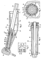
- Fig. 1
- ein erfindungsgemäßes medizinisches, insbesondere dentalmedizinisches, Handstück im vertikale n Längsschnitt;
- Fig. 2
- das Handstück nach
Fig. 1 in einem anderen Montagezustand; - Fig. 3
- den vorderen Endabschnitt eines Montagewerkzeugs im axialen Schnitt;
- Fig. 4
- den Teilschnitt IV-IV in
Fig. 2 ; - Fig. 5
- eine vordere Aufnahmehülse mit einem darin drehbar gelagerten vorderen Wellenabschnitt als Baueinheit im axialen Schnitt.
- Fig. 1
- an inventive medical, in particular dental medical, handpiece in vertical n longitudinal section;
- Fig. 2
- the handpiece after
Fig. 1 in another mounting condition; - Fig. 3
- the front end portion of an assembly tool in axial section;
- Fig. 4
- the partial section IV-IV in
Fig. 2 ; - Fig. 5
- a front receiving sleeve with a rotatably mounted therein front shaft portion as a unit in axial section.
Das in
Die Steck/Drehkupplung wird durch eine im Querschnitt runde Kupplungsausnehmung 7 und einen darin mit geringem Bewegungsspiel einsteckbaren Kupplungszapfen 8 gebildet. Beim vorliegenden Ausführungsbeispiel ist die Kupplungsausnehmung 7 am hinteren Ende des Handstücks 3 angeordnet, und der im wesentlichen zylindrische oder stufenzylindrische Kupplungszapfen 8 erstreckt sich vom Anschlußteil 2 nach vorne. Im gekuppelten Zustand sind die Kupplungsausnehmung 7 und der Kupplungszapfen 8 durch eine Verrastungsvorrichtung mit einem andeutungsweise dargestellten Verrastungselement 9 lösbar miteinander verrastet, das in dem einen Kupplungsteil radial beweglich gelagert und durch eine Federkraft in eine die Teilungsfuge zwischen den Kupplungsteilen durchsetzende Verrastungsstellung vorgespannt ist, in der das Verrastungselement 9 in eine Ringnut im anderen Kupplungsteil einfasst. Eine solche an sich bekannte Verrastungsvorrichtung ist durch eine manuelle Zugkraftausübung zum Trennen der Kupplungsteile überdrückbar, wobei das Verrastungselement 9 selbsttätig in seine Freigabestellung verdrängt wird. Das Verrastungselement 9 ist z. B. ein radial elastisch zusammendrückbarer Federring, der in einer Außenringnut im Kupplungszapfen sitzt und in eine Innenringnut in die Kupplungsausnehmung hineinragt.The plug / rotary coupling is formed by a circular cross-section coupling recess 7 and a plug-in therein with little play coupling pin 8. In the present embodiment, the
Das Anschlußteil 2 ist in nicht dargestellter Weise mit einer flexiblen Versorgungsleitung 2a verbindbar oder verbunden, die mit einem Steuergerät verbunden ist. Das Handstück 3 ist beim Vorhandensein der Steck/Drehkupplung um 360° frei drehbar am Anschlußteil 2 gelagert, wodurch die Handhabbarkeit des Handstücks 3 verbessert wird.The connector 2 is connected or connected in a manner not shown with a flexible supply line 2a, which is connected to a control unit. The
Die Haltevorrichtung 5 weist eine Aufnahmehülse 12 zur Aufnahme des Werkzeugs 6 auf, die am werkzeugseitigen Ende eine von der Werkzeugseite her zugängliche Einstecköffnung 12a für das Werkzeug 6 bzw. dessen Halteelement hat. Die Aufnahmehülse 12 ist in einer sich quer, z.B. recht- oder stumpftwinklig, zur Längsmittelachse 13a, 13b des Handstücks 3 erstreckenden Position in einer entsprechenden Lageranordnung im vorderen Endbereich des Handstücks 3 bewegbar, z. B. drehbar, gelagert. Zur Lagerung sind zwei Drehlager 14a, 14b, z.B. Wälzlager, zwischen endseitigen Lagerzapfen der Aufnahmehülse 12 und der Innenumfangswand einer Lagerbohrung 16 angeordnet.The holding device 5 has a receiving
Die Aufnahmehülse 12 bzw. die Haltevorrichtung 5 läßt sich durch einen Antrieb 17 mit einem nicht dargestellten Antriebsmotor bewegen, der im oder außerhalb des Handstücks 3 angeordnet sein kann, z.B. im Anschlußteil 2. Beim Ausführungsbeispiel erstreckt sich längs durch das Handstück 3 bzw. Instrument 1 eine Antriebswelle 18, die mit der Aufnahmehülse 12 bzw. der Haltevorrichtung 5 in Antriebsverbindung steht.The receiving
Das Handstück 3 weist einen länglichen Schaft 21 auf, an dessen vorderem Ende ein Handstückkopf angeordnet ist, in dem die Aufnahmehülse 12 drehbar gelagert ist. Der Schaft 21 besteht aus einem hinteren Schaftabschnitt 21a und einem vorderen Schaftabschnitt 21b, die einen stumpfen Winkel W1 miteinander einschließen, der etwa 155 bis 170°, vorzugsweise etwa 160 bis 165° beträgt. Der vordere Schaftabschnitt 21b ist somit bezüglich der Längsachse 13a des hinteren Schaftabschnittes 21a um einen spitzen Winkel W2 von etwa 10 bis 30°, insbesondere etwa 15 bis 20°, zur der Einstecköffnung 12a abgewandten Seite hin winkelversetzt. Hierdurch erhält der Schaft 21 an der Seite, an der sich die Einstecköffnung 12a befindet, eine konvexe Bauchseite 21c und gegenüberliegend eine konkave Rückenseite 21d. Der Abwinklungs- oder Krümmungsscheitel ist mit 21 e bezeichnet. Der vordere Schaftabschnitt 21b erstreckt sich nach vorne konvergent zu einem verdickten Arbeitskopf 3a des Handstücks 3.The
Die Längsachse 12b bzw. Drehachse der Aufnahmehülse 12 schließt mit der Längsmittelachse 13b des vorderen Schaftabschnitts 21b einen Winkel W3 ein, der 90° betragen kann, z. B. größer als 90° ist, vorzugsweise etwa 95 bis 115°, insbesondere etwa 105° oder etwa 90 bis 105°, beträgt. Diese Winkelgrößen ergeben bei Gewährleistung einer vorteilhaften Griffstellung der das Handstück 3 ergreifenden Bedienungshand eine raumgünstige Form bezüglich einer Behandlungsstelle, insbesondere im Mundraum eines Patienten.The
Die Antriebswelle 18 besteht aus einem sich im hinteren Schaftabschnitt 21 a und darin drehbar gelagerten hinteren Wellenabschnitt 18a und einem sich im vorderen Schaftabschnitt 21b erstreckenden und darin drehbar gelagerten vorderen Wellenabschnitt 18b, die im Bereich des Scheitels 21e in Drehverbindung miteinander stehen. Beim Ausführungsbeispiel dient hierzu ein Rädergetriebe mit einem auf dem vorderen Ende des hinteren Antriebswellenabschnitts 18a angeordneten Ritzel 23a und einem am hinteren Ende des vorderen Wellenabschnitts 18b angeordneten Ritzels 23b. Dabei ist der vordere Wellenabschnitt 18b bezüglich der Längsmittelachse 13b des vorderen Schaftabschnitts 21b und auch bezüglich dem vorderen Ende des hinteren Wellenabschnitts 18a zur konkaven Rückenseite 21d hin versetzt, so daß auch das Ritzel 23b am hinteren Ende des vorderen Wellenabschnitts 18b bezüglich dem Ritzel 23b am vorderen Ende des hinteren Wellenabschnitts 18a zur konkaven Rückenseite 21 d hin versetzt ist. Vorzugsweise ist die Drehachse 18d des vorderen Wellenabschnitts 18a bezüglich der Längsmittelachse 13b des vorderen Schaftabschnitts 21b zur konkaven Rückenseite 21d so weit winkelversetzt, daß die Drehachse 18d sich parallel zur Längsmantellinie 21 f des vorderen Schaftabschnitts 21b an der konkaven Rückenseite 21d erstreckt.The
Am vorderen Ende des vorderen Wellenabschnitts 18b ist ein Ritzel 24 angeordnet, das mit einem auf der Aufnahmehülse 12 angeordneten und vorzugsweise daran einteilig angeformten Ritzel 25 kämmt, das vorzugsweise mit dem Ritzel 24 auf dessen der Einstecköffnung 12a abgewandten Seite kämmt, auf der wegen des Winkels W3 sich ein raumgünstiges Rädergetriebe verwirklichen läßt.At the front end of the
Zur Aufnahme und Lagerung der Wellenabschnitte 18a, 18b im hinteren und vorderen Schaftabschnitt 21a, 21b dienen darin angeordnete Aufnahmelöcher 26, 27, in denen die Wellenabschnitte 18a, 18b vorzugsweise mittels Aufnahmehülsen 28, 29 drehbar gelagert sind, die jeweils von hinten in das zugehörige Aufnahmeloch 26, 27 eingeschoben und axial fixiert sind. Letzteres ist jeweils vorzugsweise eine Schraubverbindung 31, 32, von denen sich die der hinteren Aufnahmehülse 28 in deren mittlerem Bereich befindet und die der vorderen Aufnahmehülse 29 in deren hinteren Endbereich befindet. Beide Schraubverbindungen 31, 32 weisen jeweils ein Außengewinde auf der zugehörigen Hülse und ein Innengewinde im zugehörigen Schaftabschnitt auf. Vorzugsweise sind Schraubverbindungen 31, 32 jeweils im Bereich einer Verdickung 28a, 29a der zugehörigen Hülse und in einer Querschnittserweiterung im zugehörigen Schaftabschnitt angeordnet. Hierdurch ergibt sich für jede Schraubverbindung 31, 32 in einem von ihr nach vorne gerichteten Abstand ein Schulterflächenanschlag 33, 34 für die zugehörige Aufnahmehülse 28, 29, wodurch diese im festgeschraubten Zustand axial genau positioniert und auch gegen ein Lösen fixiert ist. Der hintere Schaftabschnitt 21 a besteht aus zwei Längsabschnitten, nämlich einem sich vom Scheitel 21e nach hinten nur über einen Teil der hinteren Aufnahmehülse 28 erstreckenden Schafthülsenabschnitt 21g und einem dahinter angeordneten Schafthülsenabschnitt 21h, der sich bis zum hinteren Ende des Schaftes 21 erstreckt und rückseitig mit der sich ebenfalls bis zum hinteren Ende erstreckenden Aufnahmehülse 28 abschließt. Der vordere Aufnahmehülsenabschnitt 21g ist somit kürzer als der hintere Schaftabschnitt 21a. Der hintere Schafthülsenabschnitt 21h sitzt somit auf dem hinteren Endbereich der Aufnahmehülse 28, und er ist von hinten darauf aufschiebbar und durch eine Fixiervorrichtung gegen eine Rückbewegung fixiert.For receiving and supporting the
Beim Ausführungsbeispiel ist die zugehörige Fixiervorrichtung durch eine Rastvorrichtung 35 mit einer Rastausnehmung an dem einen Bauteil und einem darin einrastbaren Rastvorsprung am anderen Bauteil gebildet. Die Rastausnehmung kann durch eine Ringnut 35a in der Mantelfläche der Aufnahmehülse 28 und der Rastvorsprung durch einen Ringwulst 35b auf der Innenmantelfläche des hinteren Schafthülsenabschnitt 21h gebildet sein. Die Rastvorrichtung 35 ist durch eine axiale Kraftwirkung beim Aufschieben bzw. Abschieben des hinteren Schafthülsenabschnitt 21h überdrückbar, d. h., der Rastvorsprung leistet beim axialen Bewegen einen gewissen Widerstand, der jedoch durch die axiale Kraftwirkung überwunden wird und zwar sowohl beim Einrasten in die Rastausnehmung 35a als auch beim Ausrasten. Die Rastausnehmung 35 ist vorzugsweise in einem kurzen Abstand vom hinteren Ende des Schafthülsenabschnitts 21h und der Aufnahmehülse 28 angeordnet. Im Schafthülsenabschnitt 21h ist eine die Rastvorrichtung 35 umgebende Ringnut 36 angeordnet, die nach hinten ausmündet und die Flexibilität der Rastvorrichtung 35 verbessern kann.In the exemplary embodiment, the associated fixing device is formed by a latching
Der hintere Schafthülsenabschnitt 21h besteht vorzugsweise aus Kunststoff, wodurch die Flexibilität verbessert wird und auch der Rastvorrichtung 35 zugute kommt. Der Schafthülsenabschnitt 21h ist wenigstens in seinem hinteren Endbereich dicker bemessen als der hintere Schaftabschnitt 21a, und er verjüngt sich nach vorne auf eine Hülsendicke, die dem vorderen Schafthülsenabschnitt 21d entspricht, so daß diese beiden Teile mit ihren Außenmantelflächen an der Teilungsfuge ineinander übergehen.The rear
Dem Handstück ist eine in ihrer Gesamtheit mit 37 bezeichnete Zuführungseinrichtung für ein gasförmiges oder flüssiges Medium, wie z. B. Luft, Wasser oder ein Luft/Wasser-Gemisch zugeordnet, mit einer Zuführungsleitung 37a, die sich längs durch die Versorgungsleitung 2a, das Anschlußteil 2 und durch die Kupplung 4 bis in den vorderen Endbereich des Handstücks 3 erstreckt und auf die Behandlungsstelle gerichtet ist. Beim Ausführungsbeispiel verläuft die Zuführungsleitung 37a mit Ausnahme des hinteren Handstückbereichs außerhalb des Handstücks 3, und sie ist in diesem externen Bereich durch einen Schlauch 38 gebildet, der sich von einem Schlauchanschluß 46 im hinteren Endbereich des Handstücks 3 in den vorderen Endbereich erstreckt, und im vorderen Bereich mit einem C-förmigen Clips 39 verbunden ist, der quer auf den vorderen Schaftabschnitt 21b aufgeclipst ist.The handpiece is designated in its entirety by 37 feeding device for a gaseous or liquid medium, such. As air, water or an air / water mixture associated with a supply line 37 a, which extends longitudinally through the supply line 2 a, the connector 2 and through the coupling 4 to the front end portion of the
Zu diesem Schlauchanschluß 46 erstreckt sich die Zuführungsleitung 37a zunächst axial im Anschlußteil 2 und im Kupplungszapfen 8, in dessen Bereich sie radial ausmündet, und zwar in eine zwischen dem Kupplungszapfen 8 und der Aufnahmehülse 28 angeordnete Ringnut 41, die vorzugsweise in der Innenmantelfläche der Aufnahmehülse 28 angeordnet ist. Von der Ringnut 41 erstreckt sich die Zuführungsleitung 37a in Form eines oder mehrerer auf dem Umfang verteilt angeordneter Löcher 42 in eine Ringnut 43 zwischen der Aufnahmehülse 28 und dem hinteren Schafthülsenabschnitt 21h, wobei die Ringnut 43 vorzugsweise in der Mantelfläche der Aufnahmenhülse 28 angeordnet ist. Von der Ringnut 43 erstreckt sich ein Loch 44 im hinteren Schafthülsenabschnitt 21h nach außen, von dem sich ein Kanal 45 zum Schlauchanschluß 46 hin erstreckt, der beim Ausführungsbeispiel durch eine vorzugsweise einteilig an dem Schafthülsenabschnitt 21h angeformte und sich z.B. axial oder schräg nach vorne erstreckende Schlauchtülle 46a gebildet ist, auf die der Schlauch 38 aufgesteckt und somit verbunden ist. Der Kanal 44 erstreckt sich vorzugsweise so schräg, daß er vom vorderen Ende des Schafthülsenabschnitts 21h her (dargestellt) oder vom hinteren Ende her (nicht dargestellt) eingebohrt werden kann.To this
Zur Abdichtung der Ringnuten 41, 43 sind zwischen dem Kupplungszapfen 8 und der Aufnahmehülse 28 sowie zwischen dieser und dem Schafthülsenabschnitt 21h Ringdichtungen angeordnet. Diese können durch in Ringnuten angeordnete O-Ringe 47, 48 gebildet sein. Bei den Ringnuten kann es sich um Innenringnuten im Schafthülsenabschnitt 21h oder in der Aufnahmehülse 28 (nicht dargestellt) oder um Außenringnuten in der Aufnahmehülse 28 und im Kupplungszapfen 8 handeln, wie es dargestellt ist.To seal the
Die Aufnahmehülsen 28, 29 bilden jeweils mit den darin drehbar gelagerten Wellenabschnitten und jeweils zwei in einem axialen Abstand voneinander angeordneten Wälzlagern und den zugehörigen Zahnrädern eine vorfertigbare Hülsenbaueinheit, die sich für die Erstmontage oder auch bei einem Austausch einfach und schnell montieren bzw. austauschen lassen. Zum Ein- bzw. Ausschrauben sind an beiden Aufnahmehülsen 28, 29 jeweils am hinteren Ende und von hinten zugänglich Drehangriffselemente 53, 54 angeordnet, mit denen jeweils ein Drehwerkzeug 55 formschlüssig verbindbar ist.
Wenn das Ritzel 23b so groß ist, daß es die Zugänglichkeit der Drehangriffselemente 54 von hinten verdeckt, ist es mit Zähnen und Zahnlücken in gleicher Anzahl wie die Zähne und Zahnlücken des Ritzels 23b auszubilden. Bei einer solchen Ausgestaltung können die Zähne 57 des Drehwerkzeugs 55 durch die Zahnlücken des Ritzels 23b hindurch in die Zahnlücken der Drehangriffselemente 54 gesetzt und somit formschlüssig mit diesen verbunden werden: Diese Ausgestaltung ermöglichst es, bei den beengten Raumverhältnissen eines dentalmediznischen Handstücks 3 trotz einer verhältnismäßig großen Ausgestaltung des Ritzels 23b die Zugänglichkeit zu den Drehangriffselementen 54 der Aufnahmehülse 29 zu gewährleisten.If the
Die als eigenständige Baueinheit vorgefertigte vordere Aufnahmehülse 29 besteht aus einem Hülsenkörper 61, dem Wellenabschnitt 18b mit den darauf endseitig angeordneten Ritzeln 24, 54 und zwei Drehlagern 52, insbesondere Wälzlagern, die in den beiden Endbereichen des Wellenabschnitts 18b darauf sitzen und in endseitigen Lagerbohrungen 62, 63 jeweils vom zugehörigen Hülsenkörperende her eingesetzt sind und dabei mit ihren Außenringen innenseitig an einer Schulterfläche 64 der Lagerbohrungen 62, 63 anliegen, wobei die Ritzel 24, 54 an den Außenseiten der Innenringe der Drehlager 52 anliegen. Durch diese Ausbildung sind die vorbeschriebenen Teile der Aufnahmehülse 29 unter Berücksichtigung eines erforderlichen Bewegungsspiel axial und radial bestimmt. Die Aufnahmehülse 29 bildet somit eine vormontierte Baueinheit, die wahlweise in den vorderen Schaftabschnitt 21b von hinten einsteckbar und einschraubbar und gegen den Schulterflächenanschlag 34 axial festlegbar ist. Das Einschrauben von hinten ist möglich, weil im hinteren Schaftabschnitt 21 a soviel Freiraum vorhanden ist, daß die Aufnahmehülse 29 wie vorbeschrieben montierbar ist.The prefabricated as an independent unit
Beim vorliegenden Ausführungsbeispiel weist der hintere Rand 21 i der Öffnung 21j des Aufnahmehülsenabschnitts 21 g einen Abstand a von einer gedachten Verlängerung der Dreh- und Längsmittelachse 18d des vorderen Wellenabschnitts 18b auf, der so groß ist, daß die Aufnahmehülse 29 bei einer koaxialen Bewegung von hinten einführbar und einschraubbar und wieder entfernbar ist. In der Anschlagposition stehen die Ritzel 24, 25 zwischen dem vorderen Wellenabschnitt 18b und der Aufnahmehülse 12 in Eingriff.In the present embodiment, the
Zum Fest- und Losschrauben der Aufnahmehülse 29 dienen die Drehangriffselemente 54 am hinteren Ende des Hülsenkörpers 61, die mit dem stangenförmigen Drehwerkzeug 55 von hinten zugänglich sind, daß an seinem hinteren Ende ebenfalls ein Drehangriffsmittel 65, z. B. einen Sechskant, aufweist und so lang bemessen ist, daß es von hinten zugänglich ist. Beim Ausführungsbeispiel überragt das Drehwerkzeug 55 den hinteren Rand 21i mit dem Drehangriffsmittel 65. Das Drehwerkzeug 55 weist etwa die gleiche Querschnittsgröße auf wie die Aufnahmehülse 29, insbesondere im Bereich deren Verdickung 29a. Deshalb kann auch das Drehwerkzeug 55 bei einer bezüglich der Drehachse 18d koaxialen Anordnung und linearer Zuführungsbewegung zum Drehangriffselement 54 in Arbeitsposition bewegt und funktionsgerecht gedreht werden.For fixing and unscrewing the receiving
Die Querschnittsabmessung b des Drehwerkzeugs 55 in seinem vorderen Endbereich ist beim vorliegenden Ausführungsbeispiel, bei dem das Ritzel 23b die Stirnseite des Hülsenkörpers 61 von hinten überdeckt, an den Außendurchmesser des Ritzels 23b angepaßt. Die Drehangriffselemente 53 am Drehwerkzeug 55 sind durch von dessen Stirnseite nach vorne abstehende Zähne gebildet, die an die Größe der Zahnlücken des Ritzels 23b so angepaßt sind, daß sie durch die Lücken hindurchsteckbar sind und bis zwischen die Drehangriffselemente 54 am hinteren Ende des Hülsenkörpers 61 reichen, die vorzugsweise nach hinten abstehende Zähne gebildet sind, die ebenfalls so ausgebildet sind, daß die Zähne des Drehwerkzeugs 55 zwischen die Zähne des Hülsenkörpers 61 steckbar sind. Durch das Aufstecken wird das Ritzel 23b im Hohlraum 56 des Drehwerkzeugs 55 aufgenommen, wodurch das Drehwerkzeug 55 eine Führung erhält, die das Druckwerkzeug 55 quer positioniert und ein Abrutschen vom Zahneingriff verhindert.The cross-sectional dimension b of the
Die nur in
Der hintere Schulterflächenanschlag 33 für die hintere Aufnahmehülse 28 im hinteren Schaftabschnitt 21a und der vordere Schulterflächenanschlag 34 für die vordere Aufnahmehülse 29 im vorderen Schaftabschnitt 21d befinden sich in Längspositionen im Schaft 21, in denen die vormontierten Aufnahmehülsen 28, 29 so angeordnet sind, daß das hintere Ritzelpaar 23a, 23b und das vordere Ritzelpaar 24, 25 sich in den richtigen Kämmpositionen befinden. Ein axiales Ausrichten der Aufnahmehülsen 28, 29 ist deshalb nicht erforderlich.The rear shoulder stop 33 for the
Zusätzlich zu den vorbeschriebenen Konstruktionsparametern, die das Einführen und Ein- bzw. Ausschrauben der vorderen Aufnahmehülse 29 von hinten gewährleisten, werden noch folgende Konstruktionsparameter beschrieben, die diese Zugänglichkeit von hinten weiter verbessern.In addition to the above-described design parameters, which ensure the insertion and unscrewing or unscrewing of the front receiving
Der vordere Wellenabschnitt 18b ist so in dem vorderen Schaftabschnitt 21 b angeordnet, daß das hintere Ende des vorderen Wellenabschnitts 18b näher am durch die Abwinklung der beiden Schaftabschnitt 21a, 21 gebildeten konkaven Rückenseite 21 d des Schaftes 21 liegt als an der konvexen Bauchseite 21c. Das hintere Ende des vorderen Wellenabschnitts 18d bzw. der vorderen Aufnahmehülse 29 ist somit bezüglich an sich bekannten Ausgestaltungen, bei denen die Mittel- bzw. Drehachse 18d des Wellenabschnitts 18b koaxial zur Längsmittelachse 13b des vorderen Schaftabschnitts 21b angeordnet ist, zur Rückenseite 21d hin winkelversetzt. Durch diesen Winkelversatz wird die Zugänglichkeit von hinten verbessert, weil die Position des hinteren Endes des vorderen Wellenabschnitts 18d bzw. der vorderen Aufnahmehülse 29 bezüglich des hinteren Randes des Aufnahmeloches 26 im hinteren Schaftabschnitt 21 a günstiger ist.The
Es ist somit möglich, den hinteren Rand des Aufnahmelochs 26 an der Bauchseite 21 c durch entsprechende Querschnittsbemessungen der vorderen Aufnahmehülse 29 des Aufnahmeloches 26 und des axialen Abstands des hinteren Randes des Aufnahmeloches 26 den hinteren Rand des Aufnahmeloches 26 an der Bauchseite 21c so zu positionieren, daß der Lochrand den Abstand a zur Verlängerung der Längsmittelachse der vorderen Aufnahmehülse 29 aufweist, der gleich oder größer ist als die halbe Querschnittsabmessung der Aufnahmehülse 29 und/oder des Drehwerkzeugs 59, so daß diese Teile bei bezüglich der Längsmittelachse der Aufnahmehülse 29 koaxialer Bewegung montiert bzw. demontiert oder bezüglich des Drehwerkzeugs 59 in Arbeitsstellung gebracht und wieder entfernt werden können.It is thus possible to position the rear edge of the receiving hole 26 on the
Die Drehachse 18d bzw. die Längsmittelachse des vorderen Wellenabschnitts 18b bzw. der vorderen Aufnahmehülse 29 erstreckt sich vorzugsweise parallel zur Außenseite des vorderen Schaftabschnitts 21b an der konkaven Rückenseite 21d. Hierdurch läßt sich der vorhandene Innenraum im Schaft 21 besonders günstig ausnutzen.The axis of
Dagegen erstreckt sich die Drehachse 13a des hinteren Wellenabschnitts 18a bzw. die Längsmittelachse der hinteren Aufnahmehülse 29 koaxial im hinteren Schaftabschnitt 21 a, der sich wenigstens in seinem vorderen Bereich mit gleicher Querschnittsgröße erstreckt. Unter Berücksichtigung der Abwinklung zwischen den Schaftabschnitten ergibt sich dabei eine Position für das vordere Ritzel 23a des hinteren Wellenabschnitts 18a, die bezüglich des hinteren Ritzels 23b des vorderen Wellenabschnitts 18b zur Bauchseite 21c hin versetzt ist. Die beiden Ritzel 23a, 23b kämmen somit an der Rückenseite des vorderen Ritzels 23a und der Bauchseite des hinteren Ritzels 23b der Wellenabschnitte 18a, 18b. Auch hierbei läßt sich der vorhandene Innenraum für die angestrebte Raumausnutzung dadurch ausnutzen, daß im Bereich des Abwinklungsscheitels das Aufnahmeloch 26 sich bis in den hinteren Endbereich des vorderen Schaftabschnitts 21b hinein erstreckt und im Abwinklungsbereich einen Freiraum 23c für die miteinander kämmenden Ritzel 23a, 23b bildet. An der Rückenseite ist das Aufnahmeloch 27 nach hinten bis in den Übergangsbereich des hinteren Schaftabschnitt 21a verlängert. Hierdurch wird ein Freiraum 27a geschaffen, durch den das Drehwerkzeug 55 geschoben werden kann.In contrast, the axis of rotation 13a of the rear shaft portion 18a and the longitudinal center axis of the
Beim vorliegenden Ausführungsbeispiel besteht ein weiterer Konstruktionsparameter darin, daß der hintere Schaftabschnitt 21 a auf eine Länge L gekürzt werden kann, bei dem die koaxiale Zugänglichkeit zum vorderen Wellenabschnitt 18b bzw. zur vorderen Aufnahmehülse 29 gewährleistet ist. Dieses Kürzen erfolgt durch eine Demontage des Schafthülsenabschnitts 21h und der hinteren Aufnahmehülse 28. Bei dem soweit gekürzten Handstück 3 bzw. Schaft 21 gemäß
Die Zugänglichkeit läßt sich somit auch dadurch verbessern, daß der hintere Schaftabschnitt 21b gekürzt werden kann, so daß sich für den Rand 21e an der Bauchseite 21c eine bezüglich der Flucht mit der vorderen Aufnahmehülse 29 günstigere Position ergibt, in der die vordere Aufnahmehülse 29 oder das Drehwerkzeug 55 durch im wesentlichen koaxiales Bewegen von hinten montierbar oder demontierbar bzw. in Funktionsstellungbringbar und aus der Funktionsstellung entfernbar sind. Nach der Montage der vorderen Aufnahmehülse 20 kann der hintere Schaftabschnitt 21b wieder verlängert werden, was beim Ausführungsbeispiel durch den Einbau der hinteren Aufnahmehülse 28 erfolgt. Bereits hierdurch könnte die Verlängerung des hinteren Schaftabschnitts 21 a abgeschlossen sein, wobei der hintere Schaftabschnitt 21a sich bis zum hinteren Ende der montierten hinteren Aufnahmehülse 28 erstrecken kann.The accessibility can thus also improve that the
Beim vorliegenden Ausführungsbeispiel ist zusätzlich der Hülsenschaftabschnitt 21h vorhanden, der für eine Verkürzung abgezogen und für eine Verlängerung wieder aufgeschoben wird. Zur axialen Positionierung des Hülsenschaftabschnitts 21h dient eine Schnellschlußverbindung, die beim Ausführungsbeispiel durch eine Rastverbindung 35 gebildet ist und ein schnelles und handhabungsfreundliches Abziehen und wieder Aufschieben des Hüllenschaftabschnitts 21h ermöglicht.In the present embodiment, in addition, the
Claims (3)
- A medical, in particular a dental, handpiece (3) having a shank (21) which consists of a forward and a rearward shank section (21a, 21b) which together enclose an obtuse angle (W1),
having a working head (3a) at the forward end of the forward shank section (21b), which tapers towards the working head (3a),
and having in the shank (21) a drive shaft (18) that consists of a forward and a rearward shaft section (18a, 18b) which are connected together in terms of drive,
wherein the rearward shaft section (18a) extends and is rotatably mounted in the rearward shank section (21a), and wherein the forward shaft section (18b) extends and is rotatably mounted in the forward shank section (21b),
wherein the forward end of the forward shaft section (18b) is connected in terms of drive to a tool holder that is movably mounted in the working head (3a), and wherein the forward shaft section (18b) is mounted in a receiving sleeve (29),
characterised in that
the receiving sleeve (29) can be screwed into the forward shank section (21b) from the rear, and in that arranged on the receiving sleeve (29), at the rearward end and so as to be accessible from the rear, there are rotary engagement elements (54) with which a rotary tool can be connected in a form-locking manner. - A handpiece according to claim 1,
characterised in that
the forward shaft section (18b) is arranged in the shank (21) in such a way that its rearward end lies closer to the concave rear side (21d) of the shank (21) formed by the angling of the two shank sections (21a, 21b) than to the convex bulge side (21c). - A handpiece according to claim 1 or 2,
characterised in that
the relevant construction parameters of the handpiece (3) are selected so that the receiving sleeve (29) can be pushed by means of a linear movement through the opening (21f) at the end of the rearward shank section (21a) into the forward shank section (21b) and can be anchored there.
Applications Claiming Priority (1)
| Application Number | Priority Date | Filing Date | Title |
|---|---|---|---|
| DE102005016049A DE102005016049A1 (en) | 2005-04-07 | 2005-04-07 | Medical handpiece with an angled shaft |
Publications (3)
| Publication Number | Publication Date |
|---|---|
| EP1709933A2 EP1709933A2 (en) | 2006-10-11 |
| EP1709933A3 EP1709933A3 (en) | 2006-11-08 |
| EP1709933B1 true EP1709933B1 (en) | 2012-10-24 |
Family
ID=36586003
Family Applications (1)
| Application Number | Title | Priority Date | Filing Date |
|---|---|---|---|
| EP06006455A Not-in-force EP1709933B1 (en) | 2005-04-07 | 2006-03-28 | Medical handpiece with a shaft forming an angle |
Country Status (3)
| Country | Link |
|---|---|
| US (1) | US7736146B2 (en) |
| EP (1) | EP1709933B1 (en) |
| DE (1) | DE102005016049A1 (en) |
Families Citing this family (3)
| Publication number | Priority date | Publication date | Assignee | Title |
|---|---|---|---|---|
| EP3175816B1 (en) * | 2013-03-04 | 2019-02-27 | W & H Dentalwerk Bürmoos GmbH | Medical, in particular dental contra-angle handpiece |
| EP3052028B1 (en) | 2014-04-30 | 2020-06-03 | Gyrus ACMI, Inc. (d.b.a.Olympus Surgical Technologies America) | Rotary tool with improved coupling assembly |
| JP7279912B2 (en) * | 2018-10-05 | 2023-05-23 | 医療法人社団プレシャスワン | Interdental space-making device and space-making method |
Family Cites Families (19)
| Publication number | Priority date | Publication date | Assignee | Title |
|---|---|---|---|---|
| US2010421A (en) * | 1933-05-23 | 1935-08-06 | Terry Walter John | Angular attachment for dental handpieces |
| US2025779A (en) * | 1934-02-16 | 1935-12-31 | Gustav A Roelke | Dental tool |
| US2923060A (en) * | 1957-01-08 | 1960-02-02 | Staunt Martin | Dental handpieces |
| DE1100876B (en) * | 1957-05-31 | 1961-03-02 | Ritter Co Inc | Dental handpiece |
| GB1472586A (en) * | 1973-07-06 | 1977-05-04 | Kaltenbach & Voigt | Dental handpiece |
| DE2644458B2 (en) * | 1976-10-01 | 1981-06-25 | Kaltenbach & Voigt Gmbh & Co, 7950 Biberach | Dental handpiece |
| ATE9543T1 (en) * | 1979-11-29 | 1984-10-15 | Siemens Aktiengesellschaft | DENTAL HANDPIECE ARRANGEMENT. |
| EP0029863B1 (en) * | 1979-11-29 | 1984-05-16 | Siemens Aktiengesellschaft | Dental handpiece assembly |
| IT1151940B (en) | 1981-08-03 | 1986-12-24 | Micro Mega Sa | DEVICE FOR SOLIDLY TAKING THE TRANSMISSION COMPLEX IN THE BODY OF A CONTRA-ANGLE FROM DENTISTRY |
| DE8217760U1 (en) * | 1982-06-22 | 1982-10-14 | Gebrüder Wagschal GmbH & Co KG Feinmechanik, Feinoptik, Medizintechnik, 2804 Lilienthal | TURNING INSTRUMENT FOR INSERTING DENTAL IMPLANTS |
| DE3433877C1 (en) * | 1984-09-14 | 1986-04-10 | Kaltenbach & Voigt Gmbh & Co, 7950 Biberach | Dental handpiece |
| DE3507083A1 (en) * | 1985-02-28 | 1986-09-04 | Kaltenbach & Voigt Gmbh & Co, 7950 Biberach | DENTAL HANDPIECE |
| DE4417810C2 (en) | 1994-05-20 | 1997-10-23 | Kaltenbach & Voigt | Medical or dental handpiece |
| CA2265867C (en) * | 1996-09-23 | 2007-05-29 | William David Sale | Dental prophylaxis angle and a pivotable prophy cup therefor |
| AT404550B (en) * | 1997-07-02 | 1998-12-28 | Rosenstatter Otto Dr | DENTAL HANDPIECE |
| US6106287A (en) * | 1998-12-11 | 2000-08-22 | Yates; Davis | Filter system for coupling of a dental handpiece |
| DE10208692A1 (en) | 2001-08-28 | 2003-03-20 | Kaltenbach & Voigt | Medical or dental medical handpiece with a turned part mounted in a roller bearing |
| ITBO20020617A1 (en) * | 2002-09-30 | 2004-04-01 | Castellini Spa | DENTAL HANDPIECE. |
| IL154561A0 (en) * | 2003-02-20 | 2003-09-17 | Yechiel Cohen | Dental screwdriver |
-
2005
- 2005-04-07 DE DE102005016049A patent/DE102005016049A1/en not_active Withdrawn
-
2006
- 2006-03-28 EP EP06006455A patent/EP1709933B1/en not_active Not-in-force
- 2006-04-05 US US11/399,094 patent/US7736146B2/en not_active Expired - Fee Related
Also Published As
| Publication number | Publication date |
|---|---|
| EP1709933A2 (en) | 2006-10-11 |
| US20070264610A1 (en) | 2007-11-15 |
| DE102005016049A1 (en) | 2006-10-12 |
| US7736146B2 (en) | 2010-06-15 |
| EP1709933A3 (en) | 2006-11-08 |
Similar Documents
| Publication | Publication Date | Title |
|---|---|---|
| DE7729110U1 (en) | Dental handpiece | |
| EP1208809B1 (en) | Medical or dental hand-piece having at least one rotary part | |
| EP1378208B1 (en) | Medical or dental handpiece with a rear and a front handpiece section | |
| EP1709931B1 (en) | Motor element, in particular dental hand piece with a releasable coupling for a tool holder | |
| EP1420712B1 (en) | Medical or dental handpiece with a rotary part mounted on an antifriction bearing | |
| EP0682921A2 (en) | Medical or dental handpiece | |
| EP1709933B1 (en) | Medical handpiece with a shaft forming an angle | |
| EP0029863B1 (en) | Dental handpiece assembly | |
| DE10229649A1 (en) | Medical or dental handpiece with a push button to release a tool | |
| EP2025300B1 (en) | Medical or dental handpiece | |
| EP2522297B1 (en) | Handheld dental instrument with elongated grip sleeve | |
| DE2653588C2 (en) | Dental handpiece | |
| EP0029861B1 (en) | Dental handpiece assembly | |
| EP2124812B1 (en) | Medical handle piece in particular for dental medicine with two separate outlet openings for media | |
| EP1234548B1 (en) | Medical or dental treatment instrument with a filter element | |
| EP0271597B1 (en) | Check valve for installation in the fluid conduit of a medical apparatus | |
| DE102019007592B4 (en) | Cleaning device for cleaning interdental spaces and brush head for such a cleaning device | |
| DE102008042175A1 (en) | Dental ultrasound instrument | |
| DE102004036454A1 (en) | Medical, in particular dental medical, handpiece with a clamping sleeve for a tool | |
| DE102011018694A1 (en) | Spinal column implant for patient, has wall teeth formed at longitudinal side of elongate hole and projecting into elongate hole, which is provided in wall of outer cylinder for temporary insertion of tool |
Legal Events
| Date | Code | Title | Description |
|---|---|---|---|
| PUAI | Public reference made under article 153(3) epc to a published international application that has entered the european phase |
Free format text: ORIGINAL CODE: 0009012 |
|
| PUAL | Search report despatched |
Free format text: ORIGINAL CODE: 0009013 |
|
| AK | Designated contracting states |
Kind code of ref document: A2 Designated state(s): AT BE BG CH CY CZ DE DK EE ES FI FR GB GR HU IE IS IT LI LT LU LV MC NL PL PT RO SE SI SK TR |
|
| AX | Request for extension of the european patent |
Extension state: AL BA HR MK YU |
|
| AK | Designated contracting states |
Kind code of ref document: A3 Designated state(s): AT BE BG CH CY CZ DE DK EE ES FI FR GB GR HU IE IS IT LI LT LU LV MC NL PL PT RO SE SI SK TR |
|
| AX | Request for extension of the european patent |
Extension state: AL BA HR MK YU |
|
| 17P | Request for examination filed |
Effective date: 20070412 |
|
| AKX | Designation fees paid |
Designated state(s): AT CH DE FR IT LI |
|
| 17Q | First examination report despatched |
Effective date: 20070622 |
|
| GRAP | Despatch of communication of intention to grant a patent |
Free format text: ORIGINAL CODE: EPIDOSNIGR1 |
|
| GRAS | Grant fee paid |
Free format text: ORIGINAL CODE: EPIDOSNIGR3 |
|
| GRAA | (expected) grant |
Free format text: ORIGINAL CODE: 0009210 |
|
| AK | Designated contracting states |
Kind code of ref document: B1 Designated state(s): AT CH DE FR IT LI |
|
| REG | Reference to a national code |
Ref country code: CH Ref legal event code: NV Representative=s name: BOHEST AG Ref country code: CH Ref legal event code: EP |
|
| REG | Reference to a national code |
Ref country code: AT Ref legal event code: REF Ref document number: 580475 Country of ref document: AT Kind code of ref document: T Effective date: 20121115 |
|
| REG | Reference to a national code |
Ref country code: DE Ref legal event code: R096 Ref document number: 502006012117 Country of ref document: DE Effective date: 20121220 |
|
| PG25 | Lapsed in a contracting state [announced via postgrant information from national office to epo] |
Ref country code: IT Free format text: LAPSE BECAUSE OF FAILURE TO SUBMIT A TRANSLATION OF THE DESCRIPTION OR TO PAY THE FEE WITHIN THE PRESCRIBED TIME-LIMIT Effective date: 20121024 |
|
| PLBE | No opposition filed within time limit |
Free format text: ORIGINAL CODE: 0009261 |
|
| STAA | Information on the status of an ep patent application or granted ep patent |
Free format text: STATUS: NO OPPOSITION FILED WITHIN TIME LIMIT |
|
| 26N | No opposition filed |
Effective date: 20130725 |
|
| REG | Reference to a national code |
Ref country code: DE Ref legal event code: R097 Ref document number: 502006012117 Country of ref document: DE Effective date: 20130725 |
|
| REG | Reference to a national code |
Ref country code: CH Ref legal event code: PCAR Free format text: NEW ADDRESS: HOLBEINSTRASSE 36-38, 4051 BASEL (CH) |
|
| REG | Reference to a national code |
Ref country code: FR Ref legal event code: PLFP Year of fee payment: 10 |
|
| PGFP | Annual fee paid to national office [announced via postgrant information from national office to epo] |
Ref country code: CH Payment date: 20150319 Year of fee payment: 10 |
|
| PGFP | Annual fee paid to national office [announced via postgrant information from national office to epo] |
Ref country code: FR Payment date: 20150319 Year of fee payment: 10 Ref country code: AT Payment date: 20150323 Year of fee payment: 10 |
|
| PGFP | Annual fee paid to national office [announced via postgrant information from national office to epo] |
Ref country code: DE Payment date: 20150330 Year of fee payment: 10 |
|
| REG | Reference to a national code |
Ref country code: DE Ref legal event code: R119 Ref document number: 502006012117 Country of ref document: DE |
|
| REG | Reference to a national code |
Ref country code: CH Ref legal event code: PL |
|
| REG | Reference to a national code |
Ref country code: AT Ref legal event code: MM01 Ref document number: 580475 Country of ref document: AT Kind code of ref document: T Effective date: 20160328 |
|
| REG | Reference to a national code |
Ref country code: FR Ref legal event code: ST Effective date: 20161130 |
|
| PG25 | Lapsed in a contracting state [announced via postgrant information from national office to epo] |
Ref country code: DE Free format text: LAPSE BECAUSE OF NON-PAYMENT OF DUE FEES Effective date: 20161001 Ref country code: LI Free format text: LAPSE BECAUSE OF NON-PAYMENT OF DUE FEES Effective date: 20160331 Ref country code: CH Free format text: LAPSE BECAUSE OF NON-PAYMENT OF DUE FEES Effective date: 20160331 Ref country code: FR Free format text: LAPSE BECAUSE OF NON-PAYMENT OF DUE FEES Effective date: 20160331 |
|
| PG25 | Lapsed in a contracting state [announced via postgrant information from national office to epo] |
Ref country code: AT Free format text: LAPSE BECAUSE OF NON-PAYMENT OF DUE FEES Effective date: 20160328 |