EP1779154B1 - Light diffusing film and system for making the film - Google Patents
Light diffusing film and system for making the film Download PDFInfo
- Publication number
- EP1779154B1 EP1779154B1 EP05773547A EP05773547A EP1779154B1 EP 1779154 B1 EP1779154 B1 EP 1779154B1 EP 05773547 A EP05773547 A EP 05773547A EP 05773547 A EP05773547 A EP 05773547A EP 1779154 B1 EP1779154 B1 EP 1779154B1
- Authority
- EP
- European Patent Office
- Prior art keywords
- plastic layer
- axis
- textured surface
- cylindrical roller
- diffusing film
- Prior art date
- Legal status (The legal status is an assumption and is not a legal conclusion. Google has not performed a legal analysis and makes no representation as to the accuracy of the status listed.)
- Expired - Lifetime
Links
Images


Classifications
-
- G—PHYSICS
- G02—OPTICS
- G02B—OPTICAL ELEMENTS, SYSTEMS OR APPARATUS
- G02B5/00—Optical elements other than lenses
- G02B5/02—Diffusing elements; Afocal elements
-
- G—PHYSICS
- G02—OPTICS
- G02B—OPTICAL ELEMENTS, SYSTEMS OR APPARATUS
- G02B6/00—Light guides; Structural details of arrangements comprising light guides and other optical elements, e.g. couplings
- G02B6/0001—Light guides; Structural details of arrangements comprising light guides and other optical elements, e.g. couplings specially adapted for lighting devices or systems
- G02B6/0011—Light guides; Structural details of arrangements comprising light guides and other optical elements, e.g. couplings specially adapted for lighting devices or systems the light guides being planar or of plate-like form
- G02B6/0033—Means for improving the coupling-out of light from the light guide
- G02B6/005—Means for improving the coupling-out of light from the light guide provided by one optical element, or plurality thereof, placed on the light output side of the light guide
- G02B6/0051—Diffusing sheet or layer
-
- B—PERFORMING OPERATIONS; TRANSPORTING
- B23—MACHINE TOOLS; METAL-WORKING NOT OTHERWISE PROVIDED FOR
- B23K—SOLDERING OR UNSOLDERING; WELDING; CLADDING OR PLATING BY SOLDERING OR WELDING; CUTTING BY APPLYING HEAT LOCALLY, e.g. FLAME CUTTING; WORKING BY LASER BEAM
- B23K26/00—Working by laser beam, e.g. welding, cutting or boring
- B23K26/08—Devices involving relative movement between laser beam and workpiece
- B23K26/0823—Devices involving rotation of the workpiece
-
- B—PERFORMING OPERATIONS; TRANSPORTING
- B23—MACHINE TOOLS; METAL-WORKING NOT OTHERWISE PROVIDED FOR
- B23K—SOLDERING OR UNSOLDERING; WELDING; CLADDING OR PLATING BY SOLDERING OR WELDING; CUTTING BY APPLYING HEAT LOCALLY, e.g. FLAME CUTTING; WORKING BY LASER BEAM
- B23K26/00—Working by laser beam, e.g. welding, cutting or boring
- B23K26/352—Working by laser beam, e.g. welding, cutting or boring for surface treatment
- B23K26/355—Texturing
-
- B—PERFORMING OPERATIONS; TRANSPORTING
- B29—WORKING OF PLASTICS; WORKING OF SUBSTANCES IN A PLASTIC STATE IN GENERAL
- B29C—SHAPING OR JOINING OF PLASTICS; SHAPING OF MATERIAL IN A PLASTIC STATE, NOT OTHERWISE PROVIDED FOR; AFTER-TREATMENT OF THE SHAPED PRODUCTS, e.g. REPAIRING
- B29C59/00—Surface shaping of articles, e.g. embossing; Apparatus therefor
- B29C59/02—Surface shaping of articles, e.g. embossing; Apparatus therefor by mechanical means, e.g. pressing
- B29C59/04—Surface shaping of articles, e.g. embossing; Apparatus therefor by mechanical means, e.g. pressing using rollers or endless belts
-
- B—PERFORMING OPERATIONS; TRANSPORTING
- B29—WORKING OF PLASTICS; WORKING OF SUBSTANCES IN A PLASTIC STATE IN GENERAL
- B29D—PRODUCING PARTICULAR ARTICLES FROM PLASTICS OR FROM SUBSTANCES IN A PLASTIC STATE
- B29D11/00—Producing optical elements, e.g. lenses or prisms
- B29D11/00663—Production of light guides
-
- G—PHYSICS
- G02—OPTICS
- G02B—OPTICAL ELEMENTS, SYSTEMS OR APPARATUS
- G02B27/00—Optical systems or apparatus not provided for by any of the groups G02B1/00 - G02B26/00, G02B30/00
- G02B27/30—Collimators
-
- G—PHYSICS
- G02—OPTICS
- G02B—OPTICAL ELEMENTS, SYSTEMS OR APPARATUS
- G02B5/00—Optical elements other than lenses
- G02B5/02—Diffusing elements; Afocal elements
- G02B5/0205—Diffusing elements; Afocal elements characterised by the diffusing properties
- G02B5/021—Diffusing elements; Afocal elements characterised by the diffusing properties the diffusion taking place at the element's surface, e.g. by means of surface roughening or microprismatic structures
- G02B5/0221—Diffusing elements; Afocal elements characterised by the diffusing properties the diffusion taking place at the element's surface, e.g. by means of surface roughening or microprismatic structures the surface having an irregular structure
-
- G—PHYSICS
- G02—OPTICS
- G02B—OPTICAL ELEMENTS, SYSTEMS OR APPARATUS
- G02B5/00—Optical elements other than lenses
- G02B5/02—Diffusing elements; Afocal elements
- G02B5/0205—Diffusing elements; Afocal elements characterised by the diffusing properties
- G02B5/021—Diffusing elements; Afocal elements characterised by the diffusing properties the diffusion taking place at the element's surface, e.g. by means of surface roughening or microprismatic structures
- G02B5/0226—Diffusing elements; Afocal elements characterised by the diffusing properties the diffusion taking place at the element's surface, e.g. by means of surface roughening or microprismatic structures having particles on the surface
-
- G—PHYSICS
- G02—OPTICS
- G02B—OPTICAL ELEMENTS, SYSTEMS OR APPARATUS
- G02B5/00—Optical elements other than lenses
- G02B5/02—Diffusing elements; Afocal elements
- G02B5/0205—Diffusing elements; Afocal elements characterised by the diffusing properties
- G02B5/0236—Diffusing elements; Afocal elements characterised by the diffusing properties the diffusion taking place within the volume of the element
- G02B5/0242—Diffusing elements; Afocal elements characterised by the diffusing properties the diffusion taking place within the volume of the element by means of dispersed particles
-
- G—PHYSICS
- G02—OPTICS
- G02B—OPTICAL ELEMENTS, SYSTEMS OR APPARATUS
- G02B5/00—Optical elements other than lenses
- G02B5/02—Diffusing elements; Afocal elements
- G02B5/0268—Diffusing elements; Afocal elements characterized by the fabrication or manufacturing method
-
- G—PHYSICS
- G02—OPTICS
- G02B—OPTICAL ELEMENTS, SYSTEMS OR APPARATUS
- G02B5/00—Optical elements other than lenses
- G02B5/02—Diffusing elements; Afocal elements
- G02B5/0273—Diffusing elements; Afocal elements characterized by the use
- G02B5/0278—Diffusing elements; Afocal elements characterized by the use used in transmission
-
- G—PHYSICS
- G02—OPTICS
- G02B—OPTICAL ELEMENTS, SYSTEMS OR APPARATUS
- G02B6/00—Light guides; Structural details of arrangements comprising light guides and other optical elements, e.g. couplings
- G02B6/0001—Light guides; Structural details of arrangements comprising light guides and other optical elements, e.g. couplings specially adapted for lighting devices or systems
- G02B6/0011—Light guides; Structural details of arrangements comprising light guides and other optical elements, e.g. couplings specially adapted for lighting devices or systems the light guides being planar or of plate-like form
- G02B6/0065—Manufacturing aspects; Material aspects
-
- G—PHYSICS
- G02—OPTICS
- G02F—OPTICAL DEVICES OR ARRANGEMENTS FOR THE CONTROL OF LIGHT BY MODIFICATION OF THE OPTICAL PROPERTIES OF THE MEDIA OF THE ELEMENTS INVOLVED THEREIN; NON-LINEAR OPTICS; FREQUENCY-CHANGING OF LIGHT; OPTICAL LOGIC ELEMENTS; OPTICAL ANALOGUE/DIGITAL CONVERTERS
- G02F1/00—Devices or arrangements for the control of the intensity, colour, phase, polarisation or direction of light arriving from an independent light source, e.g. switching, gating or modulating; Non-linear optics
- G02F1/01—Devices or arrangements for the control of the intensity, colour, phase, polarisation or direction of light arriving from an independent light source, e.g. switching, gating or modulating; Non-linear optics for the control of the intensity, phase, polarisation or colour
- G02F1/13—Devices or arrangements for the control of the intensity, colour, phase, polarisation or direction of light arriving from an independent light source, e.g. switching, gating or modulating; Non-linear optics for the control of the intensity, phase, polarisation or colour based on liquid crystals, e.g. single liquid crystal display cells
- G02F1/133—Constructional arrangements; Operation of liquid crystal cells; Circuit arrangements
- G02F1/1333—Constructional arrangements; Manufacturing methods
- G02F1/1335—Structural association of cells with optical devices, e.g. polarisers or reflectors
-
- B—PERFORMING OPERATIONS; TRANSPORTING
- B23—MACHINE TOOLS; METAL-WORKING NOT OTHERWISE PROVIDED FOR
- B23K—SOLDERING OR UNSOLDERING; WELDING; CLADDING OR PLATING BY SOLDERING OR WELDING; CUTTING BY APPLYING HEAT LOCALLY, e.g. FLAME CUTTING; WORKING BY LASER BEAM
- B23K2103/00—Materials to be soldered, welded or cut
- B23K2103/30—Organic materials
- B23K2103/42—Plastics other than composite materials
-
- B—PERFORMING OPERATIONS; TRANSPORTING
- B23—MACHINE TOOLS; METAL-WORKING NOT OTHERWISE PROVIDED FOR
- B23K—SOLDERING OR UNSOLDERING; WELDING; CLADDING OR PLATING BY SOLDERING OR WELDING; CUTTING BY APPLYING HEAT LOCALLY, e.g. FLAME CUTTING; WORKING BY LASER BEAM
- B23K2103/00—Materials to be soldered, welded or cut
- B23K2103/50—Inorganic materials other than metals or composite materials
-
- B—PERFORMING OPERATIONS; TRANSPORTING
- B29—WORKING OF PLASTICS; WORKING OF SUBSTANCES IN A PLASTIC STATE IN GENERAL
- B29C—SHAPING OR JOINING OF PLASTICS; SHAPING OF MATERIAL IN A PLASTIC STATE, NOT OTHERWISE PROVIDED FOR; AFTER-TREATMENT OF THE SHAPED PRODUCTS, e.g. REPAIRING
- B29C59/00—Surface shaping of articles, e.g. embossing; Apparatus therefor
- B29C59/02—Surface shaping of articles, e.g. embossing; Apparatus therefor by mechanical means, e.g. pressing
- B29C59/022—Surface shaping of articles, e.g. embossing; Apparatus therefor by mechanical means, e.g. pressing characterised by the disposition or the configuration, e.g. dimensions, of the embossments or the shaping tools therefor
- B29C2059/023—Microembossing
-
- G—PHYSICS
- G02—OPTICS
- G02B—OPTICAL ELEMENTS, SYSTEMS OR APPARATUS
- G02B6/00—Light guides; Structural details of arrangements comprising light guides and other optical elements, e.g. couplings
- G02B6/0001—Light guides; Structural details of arrangements comprising light guides and other optical elements, e.g. couplings specially adapted for lighting devices or systems
- G02B6/0011—Light guides; Structural details of arrangements comprising light guides and other optical elements, e.g. couplings specially adapted for lighting devices or systems the light guides being planar or of plate-like form
- G02B6/0033—Means for improving the coupling-out of light from the light guide
- G02B6/005—Means for improving the coupling-out of light from the light guide provided by one optical element, or plurality thereof, placed on the light output side of the light guide
- G02B6/0053—Prismatic sheet or layer; Brightness enhancement element, sheet or layer
-
- Y—GENERAL TAGGING OF NEW TECHNOLOGICAL DEVELOPMENTS; GENERAL TAGGING OF CROSS-SECTIONAL TECHNOLOGIES SPANNING OVER SEVERAL SECTIONS OF THE IPC; TECHNICAL SUBJECTS COVERED BY FORMER USPC CROSS-REFERENCE ART COLLECTIONS [XRACs] AND DIGESTS
- Y10—TECHNICAL SUBJECTS COVERED BY FORMER USPC
- Y10S—TECHNICAL SUBJECTS COVERED BY FORMER USPC CROSS-REFERENCE ART COLLECTIONS [XRACs] AND DIGESTS
- Y10S359/00—Optical: systems and elements
- Y10S359/90—Methods
Definitions
- a light diffusive film has been developed for receiving light and diffusing the light.
- the light diffusive film is manufactured using multiple manufacturing steps. First, a plurality of polystyrene beads are disposed in an acrylate solution. The acrylate solution is then applied to a surface of a plastic film. Thereafter, the plastic film is heated to cure the acrylate and to bond the polystyrene beads to the plastic film.
- a significant drawback with the manufacturing process of the light diffusive film is that it requires several relatively complex steps to coat the film with the acrylate solution and polystyrene beads. Further, the manufacturing process is relatively expensive to perform.
- Document US 5,944,405 discloses a light diffusing film.
- a diffusing film, methods of manufacturing such a film, systems and a tool are provided according to the invention as defined in the claims.
- a light collimating and diffusing film in accordance with another exemplary embodiment includes a unitary layer wherein greater than or equal to 80 percent of a total mass of the unitary layer comprises a polycarbonate compound.
- the unitary layer has a first side and a second side opposite the first side and at least a first peripheral edge.
- the first side has a first textured surface, wherein between 7 to 20 percent of slope angles on the first textured surface proximate a first axis have a value between zero and five degrees.
- the first axis is substantially parallel to the first peripheral edge.
- the plastic layer collimates light propagating therethrough.
- the back lighted device 20 includes a light source 22, a reflector film 24, a light guide 26, a light collimating and diffusing film 28, a light collimating film 30, a light collimating film 32, and a light diffuser film 34.
- the light source 22 is disposed at a first end of the light guide 26.
- the reflector film 24 is disposed, proximate a first side of the light guide 26.
- a first side of the light collimating and diffusing film 28 is disposed proximate a second side of the light guide 26 and is spaced apart from the light guide 26 utilizing posts 36, 38.
- the posts 36, 38 form an air gap 40 between the light guide 26 and the film 28.
- the light collimating film 30 is disposed proximate a second side of the film 28.
- the light collimating film 32 is disposed proximate the light collimating film 30 and the light diffusing film 34 is disposed proximate the light collimating film 32.
- the light source 22 emits a light beam 42 that propagates through the light guide 26 and is refracted therein toward an axis 44 that is substantially perpendicular to a top surface of the light guide 26.
- the light beam 42 exits the light guide 26 and the air gap 40, the light beam 42 is refracted away from the axis 44 at approximately 45 degrees.
- the film 28 refracts the light beam 42 toward the axis 44. Thereafter, when the light beam 42 exits the film 28 to light beam is refracted away from the axis 44 at approximately 31 degrees.
- the light beam 42 enters the bottom side of the light collimating film 30 at a 31 degree angle relative of the axis 44 and propagates through the film 30.
- the film 30 refracts the light beam at a top surface thereof to a zero degree angle relative to the axis 44. Because the light beam enters film 32 at a zero degree angle relative to the axis 44, the film 32 provides a relatively high luminance along axis 44.
- the film 28 is utilized to refract light beams toward the axis 44.
- the film 28 is constructed from a unitary plastic layer having a thickness in a range of 0.025-10 millimeters. Of course, the film 28 can be constructed with a thickness less than 0.025 millimeters or greater than 10 millimeters.
- the film 28 has an optical brightener compound disposed in the plastic layer wherein a mass of the optical brightener compound is in a range of 0.001-1.0 percent of a total mass of the plastic layer.
- the film 28 further includes an antistatic compound, such as fluorinated phosphonium sulfonate, disposed in the plastic layer.
- Fluorinated phosphonium sulfonate has a general formula: ⁇ CF 3 (CF 2 ) n (SO 3 ) ⁇ ⁇ ⁇ P(R 1 )(R 2 )(R 3 )(R 4 ) ⁇ ⁇ wherein F is fluorine; n is an integer of from 1-12, S is sulfur; R 1 , R 2 and R 3 are the same element, each having an aliphatic hydrocarbon radical of 1-8 carbon atoms or an aromatic hydrocarbon radical of 6-12 carbon atoms; and R 4 is a hydrocarbon radical of 1-18 carbon atoms.
- the film 28 further includes an ultraviolet (UV) absorber compound disposed in the plastic layer wherein a mass of the UV absorber compound is in a range of 0.01-1.0 percent of a total mass of the plastic layer.
- the film 28 includes a textured top surface 46 having a plurality of projecting portions 52 and a plurality of trough portions 54.
- the average height of the plurality of projecting portions 52 is within a range of 25-75 percent of an average width of the plurality of projecting portions. Further, the average width of the plurality of projecting portions 52 is within a range of 0.5-100 microns.
- the projecting portions 52 and the trough portions 54 are distributed on the top surface 46 to obtain a desired slope angle distribution.
- the slope angles reported in this patent application for a plastic film can be calculated from filtered two dimensional surface profile data generated using a Surfcoder ET 4000 instrument manufactured by Kosaka Laboratory Limited, Tokyo, Japan.
- the slope angles reported in this patent application for a cylindrical roller can be calculated from filtered two dimensional surface profile data generated using a Surfcoder SE 1700 ⁇ instrument also manufactured by Kosaka Laboratory Limited.
- the slope angle distribution can be determined along a predetermined reference trajectory or line on the plastic layer. Alternately, a slope angle distribution can be determined on an entire surface of the plastic layer using multiple reference trajectories or lines.
- a plurality of slope angles ( ⁇ ) can be calculated along a predetermined trajectory across textured surface 46, such as an axis 62 that is parallel to an edge 61 of the film 28, or an axis 60 that is perpendicular to the axis 62.
- the plurality of slope angles ( ⁇ ) can be calculated along a line 80 or a line 82.
- the desired slope angle distribution comprises between 7 to 20 percent of slope angles having a value between zero and five degrees.
- FIG. 4 a graph illustrating a slope angle distribution on a textured surface 46 on a first side of the film 28 in accordance with an exemplary embodiment is illustrated.
- the inventors herein have recognized that when 20 percent or less of slope angles on the textured surface 46, and preferably between 7 to 20 percent of slope angles on the surface 46, have a value between zero and five degrees, adjacent brightness enhancing films (e.g., films 30 and 32) have increased luminance with respect to the axis 44.
- adjacent brightness enhancing films e.g., films 30 and 32
- the percentage of slope angles between zero and five degrees on the textured top surface 46 controls the angle of the light that exits the film 28 and enters the light collimating film 30.
- the percentage of slope angles on the surface 46 is about 16 percent, the light exits the film 28 at a 31 degree angle relative to axis 44 as shown.
- the film 28 could be constructed with greater than 16 percent of the slope angles having a value between zero and five degrees.
- the film 28 could be constructed with less than 16 percent of the slope angles having a value between zero and five degrees.
- the film 28 also has a textured surface 48 on a second side of the film 28.
- the textured surface 48 has a slope angle distribution wherein greater than or equal to or 70 percent of the slope angles on the textured surface 48 have a value between zero and five degrees.
- the melt calendaring system 100 includes an extruder device 102, a die 104, cylindrical rollers 64, 108, 110, 112, 114, 116, a cylindrical spool 118, a roller cooling system 120, a film thickness scanner 122, motors 124, 126, 128, and a control computer 130.
- the extruder device 102 is provided to heat plastic above a predetermined temperature to induce the plastic to have a liquid state.
- the extruder device 102 is operably coupled to the die 104 and to the control computer 130.
- the extruder device 102 heats plastic therein above a predetermined temperature and urges the plastic through the die 104 to form the plastic layer 106.
- the cylindrical rollers 64, 108 are provided to receive the plastic layer 106 therebetween from the die 104 and to form a textured surface on a least one side of the plastic layer 106.
- the cylindrical rollers 64, 108 are preferably constructed from steel and are operably coupled to the roller cooling system 120.
- the cylindrical rollers 64, 108 may be constructed from other metallic or non-metallic materials known to those skilled in the art.
- the roller cooling system 120 maintains a temperature of the rollers 64, 108 below a predetermined temperature to solidify the plastic layer 106 as it passes between the rollers 64, 108.
- the cylindrical roller 64 has a textured surface 107 wherein between 7 to 20 percent of slope angles on the textured surface 107 or along at least one trajectory on the textured surface 107 have a value between zero and five degrees.
- the cylindrical roller 64 contacts a first side of the plastic layer 106, the cylindrical roller 64 forms a textured surface on the plastic layer 106, wherein between 7 to 20 percent of slope angles on the surface 46 of the layer 106 or along at least one trajectory on the textured surface 46 have a value between zero and five degrees.
- the slope angles ( ⁇ ) of the cylindrical roller 64 can be determined along a predetermined trajectory across the outer surface 107, such as a line 68 extending substantially across the roller 64 substantially perpendicular to the end 211 or a line 62 extending substantially around a periphery of the roller 64 a predetermined distance from the end 211.
- the slope angles ( ⁇ ) of the cylindrical roller 64 can be determined along a line 84 or a line 86.
- the cylindrical rollers 110, 112 are configured to receive the plastic layer 106 after the layer 106 has passed between the rollers 64, 108.
- the position of the cylindrical roller 110 can be adjusted to vary an amount of surface area of the plastic layer 106 that contacts the cylindrical roller 108.
- the cylindrical roller 110 is operably coupled to the roller cooling system 120 that maintains the temperature of the roller 110 below a predetermined temperature for solidifying the plastic layer 106.
- the cylindrical roller 112 receives a portion of the plastic layer 106 downstream of the roller 110 and directs the plastic layer 106 toward the cylindrical rollers 114, 116.
- the cylindrical rollers 114, 116 are provided to receive the plastic layer 106 therebetween and to move the plastic layer 106 toward the cylindrical spool 118.
- the cylindrical rollers 114, 116 are operably coupled to the motors 126, 124, respectively.
- the control computer 130 generates control signals (M1), (M2) which induce motors 124, 126, respectively, to rotate the rollers 116, 114 in predetermined directions for urging the plastic layer 106 towards the spool 118.
- the cylindrical spool 118 is provided to receive the textured plastic layer 106 and to form a roll of plastic layer 106.
- the cylindrical spool 118 is operably coupled to the motor 128.
- the control computer 130 generates a control signal (M3) that induces the motor 128 to rotate the spool 118 in predetermined direction for forming a roll of the plastic layer 106.
- the film thickness scanner 122 is provided to measure a thickness of the plastic layer 106 prior to the layer 106 being received by the cylindrical rollers 114, 116.
- the film thickness scanner 122 generates a signal (T1) indicative of the thickness of the plastic layer 106 that is transmitted to the control computer 130.
- an embossing system 150 for manufacturing a plastic layer 154 that can be subsequently cut into a predetermined shape to form the film 28 is illustrated.
- the embossing system 150 includes a cylindrical spool 152, a film-heating device 156, cylindrical rollers 64, 160, 162, 164, 166, 168, a cylindrical spool 170, a roller heating system 172, a film thickness scanner 174, motors 176, 178, 180, and a control computer 182.
- the cylindrical spool 152 is provided to hold the plastic layer 150 thereon. When the cylindrical spool 152 rotates, a portion of the plastic layer 150 is unwound from the spool 152 and moves toward the cylindrical rollers 64, 160.
- the film-heating device 156 is provided to heat the plastic layer 150 as it moves from the cylindrical spool 152 towards the cylindrical rollers 64, 160.
- the control computer 182 generates a signal (H1) that is transmitted to the film-heating device 156 that induces the device 156 to heat the plastic layer 150 above a predetermined temperature.
- the cylindrical rollers 64, 160 are provided to receive the plastic layer 154 therebetween from the cylindrical spool 152 and to form a textured surface on a least one side of the plastic layer 154.
- the cylindrical rollers 64, 160 are preferably constructed from steel and are operably coupled to the roller heating system 172. Of course, in an alternate embodiment, the cylindrical rollers 64, 160 may be constructed from other metallic or non-metallic materials known to those skilled in the art.
- the roller heating system 172 maintains a temperature of the rollers 64, 160 above a predetermined temperature to at least partially melt the plastic layer 154 as it passes between the rollers 64, 160.
- the cylindrical roller 64 has an outer textured surface 107 wherein between 7 to 20 percent of slope angles on the textured surface 107 have a value between zero and five degrees.
- the cylindrical roller 64 contacts a first side of the plastic layer 154, the cylindrical roller 64 forms a textured surface, on the plastic layer 154, wherein between 7 to 20 percent of slope angles on the top surface of the layer 154 have a value between zero and five degrees.
- the cylindrical rollers 162, 164 are configured to receive the plastic layer 154 after the layer 154 has passed between the rollers 64, 160.
- the position of the cylindrical roller 162 can be adjusted to vary an amount of surface area of the plastic layer 154 that contacts the cylindrical roller 160.
- the cylindrical roller 164 receives a portion of the plastic layer 154 downstream of the roller 162 and directs the plastic layer 154 toward the cylindrical rollers 166, 168.
- the cylindrical rollers 166, 168 are provided to receive the plastic layer 154 and to move the plastic layer 154 toward the cylindrical spool 170.
- the cylindrical rollers 166, 168 are operably coupled to the motors 178, 176, respectively.
- the control computer 182 generates control signals (M4), (M5) which induce motors 176, 178, respectively, to rotate the rollers 168, 166 in predetermined directions for urging the plastic layer 154 towards the spool 170.
- the cylindrical spool 170 is provided to receive the plastic layer 154 and to form a roll of plastic layer 154.
- the cylindrical spool 170 is operably coupled to the motor 180.
- the control computer 182 generates a control signal (M6) that induces the motor 180 to rotate the spool 170 in predetermined direction for forming a roll of the plastic layer 154.
- the film thickness scanner 174 is provided to measure a thickness of the plastic layer 154 prior to the layer 154 being received by the cylindrical rollers 114, 116.
- the film thickness scanner 174 generates a signal (T2) indicative of the thickness of the plastic layer 154 that is transmitted to the control computer 182.
- a system 200 for forming a textured surface on the cylindrical roller 64 in accordance with an exemplary embodiment is illustrated.
- the cylindrical roller 64 has a textured surface can be utilized in the melt calendaring system 100 or the embossing system 150 to form a textured plastic layer used to obtain the film 28.
- the system 200 includes a laser 202, a linear actuator 204, a motor 206, and a control computer 208.
- the laser 202 is provided to emit a pulsating laser beam that contacts an outer surface at a predetermined intensity to remove portions of the outer surface 209 to obtain a textured surface thereon.
- the laser beam emitted by the laser 202 has a focal diameter at the outer surface 209 of the cylindrical roller 64 in a range of 0.005-0.5 millimeters. Further, the laser beam has an energy level in a range of 0.05-1.0 Joules delivered over a time period in a range of 0.1-100 microseconds for a predetermined area of the cylindrical roller 64.
- the laser 202 is operably coupled to the control computer 208 and generates the laser beam in response to a control signal (C1) being received from the control computer 208.
- the laser 102 comprises a neodymium (Nd):yttrium, aluminum, garnet (YAG) laser configured to emit a laser beam having a wavelength of 1.06 microns.
- Nd neodymium
- YAG garnet
- any laser source capable of forming the desired textured surface on a cylindrical roller can be utilized.
- the laser 202 can be replaced with an electron beam emission device configured to form the desired textured surface on a cylindrical roller.
- the laser 202 can be replaced with an ion beam emission device configured to form the desired textured surface on a cylindrical roller.
- the linear actuator 204 is operably coupled to the laser 202 for moving the laser 202 along an axis 203.
- the axis 203 is substantially parallel to the outer surface 209 of the cylindrical roller 64.
- the linear actuator 204 moves the laser 202 relative to the cylindrical roller 64 at a speed within a range of 0.001-0.1 millimeters per second0..
- linear actuator 204 could be coupled to cylindrical roller 64 to move the roller 64 in an axial direction relative to a stationary laser.
- the motor 206 is operably coupled to the cylindrical roller 64 to rotate the roller 64 while the linear actuator 204 is moving the laser 202 along the axis 203 from an end 211 to an end 213 of the roller 64.
- the control computer 200 generates a signal (M7) that induces the motor 206 to rotate the cylindrical roller 64 at a predetermined speed.
- the motor 206 rotates the cylindrical roller 64 such that a linear speed of the outer surface 209 is within a range of 25-2500 millimeters per second.
- a cross-sectional view of a portion of a textured surface 209 of the cylindrical roller 64 is illustrated.
- the textured surface 209 was obtained utilizing the energy beam engraving system 200.
- the textured surface 209 has a slope angle distribution wherein between 7 to 20 percent of slope angles on the textured surface 209 have a value between zero and five degrees.
- FIG. 13 a cross-sectional view of a portion of a textured surface 215 of the light collimating and diffusing film 28 cut from a textured plastic layer formed by the cylindrical roller 64 is illustrated.
- the film 28 has a slope angle distribution wherein between 7 to 20 percent of slope angles on the film 28 have a value between zero and five degrees.
- the cylindrical roller 251 can be utilized either in the melt calendaring system 100 or the embossing system 150 to form a textured plastic layer that can be subsequently cut into a predetermined shape to obtain a film having the physical characteristics of film 28 described above.
- the system 230 includes a housing 232, a motor 242, a pump 244, a temperature control unit 246, a particle and metal ion replenishment unit 248, and a control computer 250.
- the housing 232 defines an interior region 234 for receiving a cylindrical roller 251.
- the housing 232 holds a fluid containing a plurality of metal ions 236 and a plurality of non-metal particles 238.
- the non-metal particles have a size or diameter in a range of 1-100 micrometers.
- the non-metal particles comprise silica particles.
- the silica particles can be solid silica particles, hollow silica particles, or porous silica particles.
- the non-metal particles comprise alumina particles.
- the alumina particles can be solid alumina particles, hollow alumina particles, or porous alumina particles.
- the non-metal particles comprise diamond particles.
- the metal ions comprise nickel ions and nickel alloy ions.
- the non-metal particles and the metal ions in the fluid chemically bond to an external surface 253 of the cylindrical roller 251 to form a textured surface.
- the cylindrical roller 251 is rotated within the fluid to obtain a textured surface wherein between 7 to 20 percent of slope angles on the textured surface have a value between zero and five degrees.
- the motor 242 is operably coupled to the cylindrical roller 251 and is provided to rotate the cylindrical roller 251 at a predetermined rotational speed.
- the motor 242 is disposed within the housing 232. In an alternate embodiment, the motor 242 is disposed outside of the housing 232 with a shaft (not shown) extending through the housing 232 coupled to the cylindrical roller 251 for rotating the roller 251.
- the control computer 250 generates a signal (M8) that induces the motor 242 to rotate the cylindrical roller 251 at a predetermined rotational speed.
- the pump 244 is provided to pump the fluid containing the non-metal particles and the metal ions from the housing 232 through the temperature control unit 246 and the particle and metal-ion replenishment unit 248.
- the control computer 250 generates a signal (PI) that induces the pump 244 to pump the fluid from housing 232 through the unit 246 and the unit 248 and back to the interior region 234.
- the temperature control unit 246 is operably coupled to the pump 244 and receives the fluid containing non-metal particles and the metal-ions from the pump 244.
- the temperature control unit 246 is provided to control a temperature of the fluid being pumped therethrough at a desired temperature that allows the co-deposition of the non-metal particles and metal-ions onto the outer surface 253 of the cylindrical roller 251.
- the temperature control unit 246 monitors a temperature of the fluid in pump therethrough and either increases or decreases the temperature of the fluid to the desired temperature.
- the particle and metal ion replenishment unit 248 is operably coupled to the temperature control unit 246 and receives the fluid containing the non-metal particles in the metal-ions from the unit 246.
- the unit 248 monitors the concentration of the non-metal particles and the metal ions during the co-deposition of the particles and metal ions on the surface 253. It will be understood, that as the non-metal particles and the metal ions are bonded to the outer surface 253 of the roller 251, the concentration of the non-metal particles and metal ions in the fluid will be decreased.
- the unit 248 measures the concentration of the non-metal particles and the metal ions in the fluid being pumped therethrough and adds an additional amount of non-metal particles and metal ions to the fluid to maintain a desired concentration of each material. After the fluid is conditioned by the unit 248, the fluid is routed to the interior region 234 of the housing 232.
- FIG. 15 a cross-sectional view of a portion of a textured surface 253 of the cylindrical roller 251 is illustrated.
- the textured surface 253 was obtained utilizing the particle and metal ion co-deposition system 230.
- the textured surface 253 has a slope angle distribution wherein between 7 to 20 percent of slope angles on the textured surface 253 have a value between zero and five degrees.
- a cross-sectional view of a portion of a textured surface 254 of the light collimating and diffusing film cut from a textured plastic layer formed by the cylindrical roller 251 is illustrated.
- the textured surface 254 has a slope angle distribution wherein between 7 to 20 percent of slope angles on the textured surface 28 have a value between zero and five degrees.
- the cylindrical roller 278 can be utilized either in the melt calendaring system 100 or the embossing system 150 to form a textured plastic layer used to obtain a film having physical characteristics substantially similar to film 28 described above.
- the system 270 includes a housing 272, a motor 280, a current source 282, and a control computer 284.
- the housing 272 defines an interior region 274 for receiving a cylindrical roller 278.
- the housing 272 holds an electrolye fluid containing a plurality of metal ions 276.
- the plurality of metal ions 276 comprise chromium ions.
- the metal ions 276 bond to the outer surface 279 of the cylindrical roller 278 to form a textured surface.
- the cylindrical roller 278 is rotated within the electrolyte fluid to obtain a textured surface wherein between 7 to 20 percent of slope angles on the textured surface have a value between zero and five degrees.
- the motor 280 is operably coupled to the cylindrical roller 278 and is provided to rotate the cylindrical roller 278 at a predetermined rotational speed for a predetermine time period.
- the motor 280 can rotate the cylindrical roller 278 at a rotational speed in a range of 1-10 revolutions per minute for a time period in a range of 0.5-50 hours.
- the motor 280 is disposed within the housing 272.
- the motor 280 is disposed outside of the housing 272 with a shaft (not shown) extending through the housing 272 coupled to the cylindrical roller 278 for rotating the roller 278.
- the control computer 284 generates a signal (M9) that induces the motor 280 to rotate the cylindrical roller 278 at the desired rotational speed.
- the current source 282 is provided to apply a predetermined electrical current density through the electrolyte fluid to induce metal ions in the electrolyte fluid to adhere to the outer surface 279 of the cylindrical roller 278.
- the current source 280 is electrically coupled between a metal bar 275 immersed in the electrolyte fluid and the cylindrical roller 278.
- the current source 280 is further operably coupled to the control computer 284.
- the control computer 284 generates a control signal (I1) that induces the current source 282 to generate an electrical current through the electrolyte fluid.
- the current source 280 generates a current density in a range of 0.001-0.1 amperes per square millimeter in the electrolyte fluid to induce the metal ions in the fluid to adhere to the cylindrical roller 278.
- a system 300 for forming a textured surface on the cylindrical roller 318 in accordance with another exemplary embodiment is illustrated.
- the cylindrical roller 318 can be utilized either in the melt calendaring system 100 or the embossing system 150 to form a textured plastic layer that can be subsequently cut into a predetermined shape to obtain a film having physical characteristics substantially similar to film 28 described above.
- the system 300 includes engraving device 302, a linear actuator 312, a motor 314, and a control computer 316.
- the engraving device 302 is provided to iteratively contact the outer surface 319 of the cylindrical roller 318 at a predetermined frequency to remove portions of the outer surface 319 to obtain a textured surface.
- the predetermined frequency is preferably within a range of 1000-1500 Khz.
- the engraving device 302 includes a piezo-electric transducer unit 304, a reciprocating member 306, a cutting tool holder 308, and a cutting tool 310.
- the piezo-electric transducer unit 304 is provided to iteratively move the reciprocating member 306 upwardly and downwardly along the axis 307 at the predetermined frequency in response to a control signal (P) received from the control computer 316.
- the reciprocating member 306 is further operably coupled to a first end of the cutting tool holder 308 that holds a cutting tool 310.
- the cutting tool 310 is provided to remove portions of the outer surface 319 of the cylindrical roller 318.
- the cutting tool 310 is constructed from a diamond having a tip diameter (D1) in a range of 2-30 micrometers.
- the cutting tool 310 has a cutting surface 311 that extends 160 degrees about a center point of the tool 310. The cutting surface 311 of the tool 310 iteratively contacts the outer surface 319 as the outer surface 319 is being rotated at a predetermined speed.
- the linear actuator 312 is operably coupled to the engraving device 302 for moving the engraving device 302 along an axis 303.
- the axis 303 is substantially parallel to the outer surface 319 of the cylindrical roller 318.
- the linear actuator 312 moves the engraving device 302 relative to the cylindrical roller 318 at a predetermined determined axial speed from a first end 321 to a second end 323 of the cylindrical roller 318.
- linear actuator 312 could be coupled to the cylindrical roller 318 to move the roller 318 in an axial direction relative to a stationary engraving device.
- the motor 314 is operably coupled to the cylindrical roller 318 to rotate the roller 318 while the linear actuator 312 is moving the engraving device 302 along the axis 303 from the end 321 to the end 323.
- the control computer 316 generates a signal (M10) that induces the motor 314 to rotate the cylindrical roller 318 at a predetermined rotational speed.
- the motor 310 rotates the cylindrical roller 318 at a rotational speed within a range of 10-200 revolutions per minute.
- a system 330 for forming a textured surface on the cylindrical roller 340 in accordance with another exemplary embodiment is illustrated.
- the cylindrical roller 340 can be utilized either in the melt calendaring system 100 or the embossing system 150 to form a textured plastic layer that can be subsequently cut into a predetermined shape to obtain a film having physical characteristics substantially similar to film 28 described above.
- the system 330 includes a housing 332, a motor 336, and a control computer 338.
- the cylindrical roller 340 has a substantially cylindrical inner portion 342 coated with a chemically resistant layer 343.
- the chemically resistant layer 343 comprises a plastic layer.
- the chemically resistant layer 343 comprises a wax layer.
- the chemically resistant layer 343 comprises a photo-resist layer.
- portions of the layer 343 are removed at the predetermined locations using a tool (not shown) having a hardness greater than the chemically resistant layer 343 but less than a hardness of the cylindrical inner portion 342.
- the chemically resistant layer 343 is removed at the predetermined locations using a lithographic process known to those skilled in the art.
- the housing 332 defines an interior region 334 for receiving a cylindrical roller 340.
- the housing 332 holds an etching solution for removing exposed portions of the inner portion 342 of the cylindrical roller 340.
- the etching solution includes nitric acid wherein 5 to 25 percent of a mass of the etching solution is nitric acid.
- the etching solution includes hydrochloric acid wherein 5 to 25 percent of a mass of the etching solution is hydrochloric acid.
- the motor 336 is operably coupled to the cylindrical roller 340 and is provided to rotate the cylindrical roller 340 at a predetermined rotational speed.
- the motor 336 is disposed within the housing 332.
- the motor 336 is disposed outside of the housing 332 with a shaft (not shown) extending through the housing 332 coupled to the cylindrical roller 340 for rotating the roller 340.
- the control computer 338 generates a signal (M11) that induces the motor 336 to rotate the cylindrical roller 341 at a predetermined rotational speed.
- the motor 336 can rotate the cylindrical roller 341 at a rotational speed in a range of 1-50 revolutions per minute.
- the cylindrical roller 390 can be utilized either in the melt calendaring system 100 or the embossing system 150 to form a textured plastic layer that can be subsequently cut into a predetermined shape to obtain a film having physical characteristics substantially similar to film 28 described above.
- the system 370 includes an electrode or an electrode array 372, a voltage source 374, a linear actuator 376, a motor 378, a pump 382, a filter 384, a dielectric fluid source 386, and a control computer 388.
- the electrode 372 is provided to iteratively discharge an electric spark that contacts an outer surface 391 to remove portions of the surface 391 to obtain a textured surface.
- the electrode 372 is operably coupled to the voltage source 374 and receives a voltage from the voltage source 374 to generate an electric spark having a voltage in a range of 100-1000 volts.
- the voltage source 374 is operably coupled to the control computer 388.
- the control computer 380 generates a signal (V2) that induces the voltage source 374 to apply a predetermined voltage to the electrode 372.
- the electrode 372 is further operably coupled to the linear actuator 376.
- the electrode 372 When the cylindrical roller 390 is being rotated, the electrode 372 is moved along axis 373 and iteratively discharges an electric spark to remove portions of the cylindrical roller 390 to form a textured surface wherein between 7 to 20 percent of slope angles on the textured surface have a value between zero and five degrees.
- the pump 382 is provided to pump a dielectric fluid from the dielectric fluid reservoir 386 through a filter 384 and finally through the nozzle 380.
- the nozzle 380 directs the dielectric fluid onto the outer surface 391 of the cylindrical roller 390.
- the dielectric fluid is utilized to conduct an electric spark therethrough to the outer surface 391 of the cylindrical roller 390.
- the nozzle 380 is further operably coupled to the linear actuator 376.
- the linear actuator 376 is operably coupled to both the electrode 372 and the nozzle 380.
- the linear actuator 376 moves the electrode 372 and the nozzle 380 along an axis 373 that is substantially parallel to the outer surface of the cylindrical roller 390.
- the linear actuator 376 moves the electrode 372 and the nozzle 380 along the axis 373 from a first end 393 to a second end 395 of the cylindrical roller 390.
- the motor 378 is operably coupled to the cylindrical roller 390 to rotate the roller 390 while the linear actuator 376 is moving both the electrode 372 and the nozzle 380 along the axis 373 from the end 393 to the end 395.
- the control computer 388 generates a signal (M12) that induces the motor 378 to rotate the cylindrical roller 390 at a predetermined rotational speed.
- the light collimating and diffusing film and the method for manufacturing the film represents a substantial advantage over other systems and methods.
- the system and method have a technical effect of providing a plastic layer having a textured surface capable of diffusing light that can readily manufactured without having any additional material being added to the plastic layer such as polystryene beads or an acrylate solution.
Landscapes
- Physics & Mathematics (AREA)
- Optics & Photonics (AREA)
- Engineering & Computer Science (AREA)
- General Physics & Mathematics (AREA)
- Mechanical Engineering (AREA)
- Manufacturing & Machinery (AREA)
- Plasma & Fusion (AREA)
- Chemical & Material Sciences (AREA)
- Health & Medical Sciences (AREA)
- Ophthalmology & Optometry (AREA)
- Dispersion Chemistry (AREA)
- Nonlinear Science (AREA)
- Mathematical Physics (AREA)
- Crystallography & Structural Chemistry (AREA)
- Shaping Of Tube Ends By Bending Or Straightening (AREA)
- Optical Elements Other Than Lenses (AREA)
- Rolls And Other Rotary Bodies (AREA)
Description
- A light diffusive film has been developed for receiving light and diffusing the light. The light diffusive film is manufactured using multiple manufacturing steps. First, a plurality of polystyrene beads are disposed in an acrylate solution. The acrylate solution is then applied to a surface of a plastic film. Thereafter, the plastic film is heated to cure the acrylate and to bond the polystyrene beads to the plastic film. A significant drawback with the manufacturing process of the light diffusive film is that it requires several relatively complex steps to coat the film with the acrylate solution and polystyrene beads. Further, the manufacturing process is relatively expensive to perform. Document
US 5,944,405 discloses a light diffusing film. - Accordingly, there is a need for a light diffusive film that can be manufactured using a simplified process without utilizing polystryene beads or an acrylate solution.
- A diffusing film, methods of manufacturing such a film, systems and a tool are provided according to the invention as defined in the claims.
- A light collimating and diffusing film in accordance with another exemplary embodiment is provided. The film includes a unitary layer wherein greater than or equal to 80 percent of a total mass of the unitary layer comprises a polycarbonate compound. The unitary layer has a first side and a second side opposite the first side and at least a first peripheral edge. The first side has a first textured surface, wherein between 7 to 20 percent of slope angles on the first textured surface proximate a first axis have a value between zero and five degrees. The first axis is substantially parallel to the first peripheral edge. The plastic layer collimates light propagating therethrough.
- Other systems and/or methods according to the embodiments will become or are apparent to one with skill in the art upon review of the following drawings and detailed description. It is intended that all such additional systems and methods be within the scope of the present invention, and be protected by the accompanying claims.
-
-
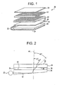
Figure 1 is an exploded view of a back lighted device in accordance with an exemplary embodiment; -
Figure 2 is a schematic of a portion of the back lighted device ofFigure 1 ; -
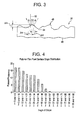
Figure 3 is a cross-sectional schematic of a light collimating and diffusing film utilized in the back lighted device ofFigure 1 in accordance with another exemplary embodiment; -
Figure 4 is a graph indicating a slope distribution on a front surface of the light collimating and diffusing film; -
Figure 5 is a top view of a cylindrical roller illustrating exemplary trajectories for determining a slope angle distribution; -
Figure 6 is a top view of a light collimating and diffusing film illustrating exemplary' trajectories for determining a slope angle distribution; -
Figure 7 is a top view of a cylindrical roller illustrating exemplary trajectories for determining a slope angle distribution; -
Figure 8 is a top view of a light collimating and diffusing film illustrating exemplary trajectories for determining a slope angle distribution; -
Figure 9 is a schematic of a melt calendaring system for manufacturing a light collimating and diffusing film in accordance with another exemplary embodiment; -
Figure 10 is a schematic of an embossing system for manufacturing a light collimating and diffusing film in accordance with another exemplary embodiment; -
Figure 11 is a schematic of an energy beam engraving system for obtaining a textured surface on a cylindrical roller in accordance with another exemplary embodiment; -
Figure 12 is a schematic of a textured surface on a cylindrical roller obtained using the energy beam engraving system ofFigure 11 ; -
Figure 13 is a schematic of a textured surface on a light collimating and diffusing film obtained using the cylindrical roller ofFigure 12 ; -
Figure 14 is a schematic of a particle and metal ion co-deposition system for obtaining a textured surface on a cylindrical roller in accordance with another exemplary embodiment; -
Figure 15 is a schematic of a textured surface on a cylindrical roller obtained using the particle and metal ion co-deposition system ofFigure 14 ; -
Figure 16 is a schematic of a textured surface on a light collimating and diffusing film obtained using the cylindrical roller ofFigure 15 ; -
Figure 17 is a schematic of a metal ion deposition system for obtaining a textured surface on a cylindrical roller in accordance with another exemplary embodiment; -
Figure 18 is a schematic of a micro-machining engraving system for obtaining a textured surface on a cylindrical roller in accordance with another exemplary embodiment; -
Figure 19 is an enlarged front view of a cutting cool utilized in the system ofFigure 18 ; -
Figure 20 is an enlarged side view of the cutting cool utilized in the system ofFigure 18 ; -
Figure 21 is a schematic of chemical etching engraving system for obtaining a textured surface on a cylindrical roller in accordance with another exemplary embodiment; -
Figure 22 is an enlarged cross-sectional view of a portion of the cylindrical roller utilized by the system ofFigure 21 ; and -
Figure 23 is a schematic of an electric discharge engraving system for obtaining a textured surface on a cylindrical roller in accordance with another exemplary embodiment. - Referring to
Figures 1 and 2 , a back lighteddevice 20 for illuminating a liquid crystal display device (not shown) is illustrated. The back lighteddevice 20 includes alight source 22, areflector film 24, alight guide 26, a light collimating and diffusingfilm 28, a light collimatingfilm 30, a light collimatingfilm 32, and alight diffuser film 34. As shown, thelight source 22 is disposed at a first end of thelight guide 26. Further, thereflector film 24 is disposed, proximate a first side of thelight guide 26. A first side of the light collimating and diffusingfilm 28 is disposed proximate a second side of thelight guide 26 and is spaced apart from thelight guide 26 utilizingposts posts air gap 40 between thelight guide 26 and thefilm 28. The light collimatingfilm 30 is disposed proximate a second side of thefilm 28. Finally, the light collimatingfilm 32 is disposed proximate the light collimatingfilm 30 and the light diffusingfilm 34 is disposed proximate the light collimatingfilm 32. - The path of an exemplary light beam propagating through both the
light guide 26 and the light collimating and diffusingfilm 28 will now be explained. Thelight source 22 emits alight beam 42 that propagates through thelight guide 26 and is refracted therein toward anaxis 44 that is substantially perpendicular to a top surface of thelight guide 26. When thelight beam 42 exits thelight guide 26 and theair gap 40, thelight beam 42 is refracted away from theaxis 44 at approximately 45 degrees. When thelight beam 42 enters the light collimating and diffusingfilm 28, thefilm 28 refracts thelight beam 42 toward theaxis 44. Thereafter, when thelight beam 42 exits thefilm 28 to light beam is refracted away from theaxis 44 at approximately 31 degrees. Thereafter, thelight beam 42 enters the bottom side of the light collimatingfilm 30 at a 31 degree angle relative of theaxis 44 and propagates through thefilm 30. Thefilm 30 refracts the light beam at a top surface thereof to a zero degree angle relative to theaxis 44. Because the light beam entersfilm 32 at a zero degree angle relative to theaxis 44, thefilm 32 provides a relatively high luminance alongaxis 44. - Referring to
Figures 2 and3 , the light collimating and diffusingfilm 28 will now be explained in greater detail. Thefilm 28 is utilized to refract light beams toward theaxis 44. Thefilm 28 is constructed from a unitary plastic layer having a thickness in a range of 0.025-10 millimeters. Of course, thefilm 28 can be constructed with a thickness less than 0.025 millimeters or greater than 10 millimeters. Thefilm 28 has an optical brightener compound disposed in the plastic layer wherein a mass of the optical brightener compound is in a range of 0.001-1.0 percent of a total mass of the plastic layer. Thefilm 28 further includes an antistatic compound, such as fluorinated phosphonium sulfonate, disposed in the plastic layer. Fluorinated phosphonium sulfonate has a general formula: {CF3(CF2)n(SO3)}θ {P(R1)(R2)(R3)(R4)}Φ wherein F is fluorine; n is an integer of from 1-12, S is sulfur; R1, R2 and R3 are the same element, each having an aliphatic hydrocarbon radical of 1-8 carbon atoms or an aromatic hydrocarbon radical of 6-12 carbon atoms; and R4 is a hydrocarbon radical of 1-18 carbon atoms. Thefilm 28 further includes an ultraviolet (UV) absorber compound disposed in the plastic layer wherein a mass of the UV absorber compound is in a range of 0.01-1.0 percent of a total mass of the plastic layer. Thefilm 28 includes a texturedtop surface 46 having a plurality of projectingportions 52 and a plurality oftrough portions 54. The average height of the plurality of projectingportions 52 is within a range of 25-75 percent of an average width of the plurality of projecting portions. Further, the average width of the plurality of projectingportions 52 is within a range of 0.5-100 microns. The projectingportions 52 and thetrough portions 54 are distributed on thetop surface 46 to obtain a desired slope angle distribution. - The slope angle distribution is a distribution of a plurality of slope angles along at least one predetermined trajectory on the light collimating and diffusing
film 28. Further, each slope angle (φ) is calculated using the following equation:
where: - (Δw) represents a predetermined width along the
textured surface 46, such as 0.5 microns for example; - (Δh) represents a height difference between (i) a lowest position on the
textured surface 46 along the width (Δw), and (ii) a highest position on thesurface 46 along the width (Δw). - The slope angles reported in this patent application for a plastic film can be calculated from filtered two dimensional surface profile data generated using a Surfcoder ET 4000 instrument manufactured by Kosaka Laboratory Limited, Tokyo, Japan. The operational settings of the Surfcoder ET 4000 instrument are as follows: Cutoff = 0.25mm, Sample Length and Evaluation Length both set at 10mm. The speed being set at 0.1 mm/second with profile data being obtained at 8000 equally spaced points.
- The slope angles reported in this patent application for a cylindrical roller can be calculated from filtered two dimensional surface profile data generated using a Surfcoder SE 1700α instrument also manufactured by Kosaka Laboratory Limited. The operational settings of the Surfcoder SE 1700α instrument are as follows: Evaluation Length = 7.2mm, Cutoff Lc = 0.800mm. The speed being set at 0.500 mm/second with profile data being obtained at 14400 points.
- The slope angle distribution can be determined along a predetermined reference trajectory or line on the plastic layer. Alternately, a slope angle distribution can be determined on an entire surface of the plastic layer using multiple reference trajectories or lines.
- For example, referring to
Figures 6 and 8 , a plurality of slope angles (φ) can be calculated along a predetermined trajectory acrosstextured surface 46, such as anaxis 62 that is parallel to anedge 61 of thefilm 28, or anaxis 60 that is perpendicular to theaxis 62. Alternately, the plurality of slope angles (φ) can be calculated along aline 80 or aline 82. In one or more of the foregoing trajectories, the desired slope angle distribution comprises between 7 to 20 percent of slope angles having a value between zero and five degrees. - Referring to
Figure 4 , a graph illustrating a slope angle distribution on atextured surface 46 on a first side of thefilm 28 in accordance with an exemplary embodiment is illustrated. The inventors herein have recognized that when 20 percent or less of slope angles on thetextured surface 46, and preferably between 7 to 20 percent of slope angles on thesurface 46, have a value between zero and five degrees, adjacent brightness enhancing films (e.g.,films 30 and 32) have increased luminance with respect to theaxis 44. - Referring to
Figures 1 and 2 , the percentage of slope angles between zero and five degrees on the texturedtop surface 46 controls the angle of the light that exits thefilm 28 and enters thelight collimating film 30. When the percentage of slope angles on thesurface 46 is about 16 percent, the light exits thefilm 28 at a 31 degree angle relative toaxis 44 as shown. In an alternate embodiment, if it is desirable for the light to exit thefilm 28 at an angle greater than 31 degrees relative to theaxis 44, then thefilm 28 could be constructed with greater than 16 percent of the slope angles having a value between zero and five degrees. In another alternate embodiment, if it is desirable for the light to exit thefilm 28 at an angle less than 31 degrees relative to theaxis 44, then thefilm 28 could be constructed with less than 16 percent of the slope angles having a value between zero and five degrees. - Referring to
Figure 3 , thefilm 28 also has a texturedsurface 48 on a second side of thefilm 28. Thetextured surface 48 has a slope angle distribution wherein greater than or equal to or 70 percent of the slope angles on thetextured surface 48 have a value between zero and five degrees. - Referring to
Figure 9 , amelt calendaring system 100 for manufacturing atextured plastic layer 106 that can be subsequently cut into a predetermined shape to form light collimating and diffusingfilm 28 is illustrated. Themelt calendaring system 100 includes anextruder device 102, adie 104,cylindrical rollers cylindrical spool 118, aroller cooling system 120, afilm thickness scanner 122,motors control computer 130. - The
extruder device 102 is provided to heat plastic above a predetermined temperature to induce the plastic to have a liquid state. Theextruder device 102 is operably coupled to the die 104 and to thecontrol computer 130. In response to a control signal (E) from thecontrol computer 130, theextruder device 102 heats plastic therein above a predetermined temperature and urges the plastic through thedie 104 to form theplastic layer 106. - The
cylindrical rollers plastic layer 106 therebetween from thedie 104 and to form a textured surface on a least one side of theplastic layer 106. Thecylindrical rollers roller cooling system 120. Of course, in an alternate embodiment, thecylindrical rollers roller cooling system 120 maintains a temperature of therollers plastic layer 106 as it passes between therollers cylindrical roller 64 has atextured surface 107 wherein between 7 to 20 percent of slope angles on thetextured surface 107 or along at least one trajectory on thetextured surface 107 have a value between zero and five degrees. Thus, when thecylindrical roller 64 contacts a first side of theplastic layer 106, thecylindrical roller 64 forms a textured surface on theplastic layer 106, wherein between 7 to 20 percent of slope angles on thesurface 46 of thelayer 106 or along at least one trajectory on thetextured surface 46 have a value between zero and five degrees. - Referring to
Figures 5 and 7 , the slope angles (φ) of thecylindrical roller 64 can be determined along a predetermined trajectory across theouter surface 107, such as aline 68 extending substantially across theroller 64 substantially perpendicular to theend 211 or aline 62 extending substantially around a periphery of the roller 64 a predetermined distance from theend 211. Alternately, the slope angles (φ) of thecylindrical roller 64 can be determined along aline 84 or aline 86. - The
cylindrical rollers plastic layer 106 after thelayer 106 has passed between therollers cylindrical roller 110 can be adjusted to vary an amount of surface area of theplastic layer 106 that contacts thecylindrical roller 108. Thecylindrical roller 110 is operably coupled to theroller cooling system 120 that maintains the temperature of theroller 110 below a predetermined temperature for solidifying theplastic layer 106. Thecylindrical roller 112 receives a portion of theplastic layer 106 downstream of theroller 110 and directs theplastic layer 106 toward thecylindrical rollers - The
cylindrical rollers plastic layer 106 therebetween and to move theplastic layer 106 toward thecylindrical spool 118. Thecylindrical rollers motors control computer 130 generates control signals (M1), (M2) which inducemotors rollers plastic layer 106 towards thespool 118. - The
cylindrical spool 118 is provided to receive thetextured plastic layer 106 and to form a roll ofplastic layer 106. Thecylindrical spool 118 is operably coupled to themotor 128. Thecontrol computer 130 generates a control signal (M3) that induces themotor 128 to rotate thespool 118 in predetermined direction for forming a roll of theplastic layer 106. - The
film thickness scanner 122 is provided to measure a thickness of theplastic layer 106 prior to thelayer 106 being received by thecylindrical rollers film thickness scanner 122 generates a signal (T1) indicative of the thickness of theplastic layer 106 that is transmitted to thecontrol computer 130. - Referring to
Figure 10 , anembossing system 150 for manufacturing aplastic layer 154 that can be subsequently cut into a predetermined shape to form thefilm 28 is illustrated. Theembossing system 150 includes acylindrical spool 152, a film-heating device 156,cylindrical rollers cylindrical spool 170, aroller heating system 172, afilm thickness scanner 174,motors control computer 182. - The
cylindrical spool 152 is provided to hold theplastic layer 150 thereon. When thecylindrical spool 152 rotates, a portion of theplastic layer 150 is unwound from thespool 152 and moves toward thecylindrical rollers - The film-
heating device 156 is provided to heat theplastic layer 150 as it moves from thecylindrical spool 152 towards thecylindrical rollers control computer 182 generates a signal (H1) that is transmitted to the film-heating device 156 that induces thedevice 156 to heat theplastic layer 150 above a predetermined temperature. - The
cylindrical rollers plastic layer 154 therebetween from thecylindrical spool 152 and to form a textured surface on a least one side of theplastic layer 154. Thecylindrical rollers roller heating system 172. Of course, in an alternate embodiment, thecylindrical rollers roller heating system 172 maintains a temperature of therollers plastic layer 154 as it passes between therollers cylindrical roller 64 has an outertextured surface 107 wherein between 7 to 20 percent of slope angles on thetextured surface 107 have a value between zero and five degrees. Thus, when thecylindrical roller 64 contacts a first side of theplastic layer 154, thecylindrical roller 64 forms a textured surface, on theplastic layer 154, wherein between 7 to 20 percent of slope angles on the top surface of thelayer 154 have a value between zero and five degrees. - The
cylindrical rollers plastic layer 154 after thelayer 154 has passed between therollers cylindrical roller 162 can be adjusted to vary an amount of surface area of theplastic layer 154 that contacts thecylindrical roller 160. Thecylindrical roller 164 receives a portion of theplastic layer 154 downstream of theroller 162 and directs theplastic layer 154 toward thecylindrical rollers - The
cylindrical rollers plastic layer 154 and to move theplastic layer 154 toward thecylindrical spool 170. Thecylindrical rollers motors control computer 182 generates control signals (M4), (M5) which inducemotors rollers plastic layer 154 towards thespool 170. - The
cylindrical spool 170 is provided to receive theplastic layer 154 and to form a roll ofplastic layer 154. Thecylindrical spool 170 is operably coupled to themotor 180. Thecontrol computer 182 generates a control signal (M6) that induces themotor 180 to rotate thespool 170 in predetermined direction for forming a roll of theplastic layer 154. - The
film thickness scanner 174 is provided to measure a thickness of theplastic layer 154 prior to thelayer 154 being received by thecylindrical rollers film thickness scanner 174 generates a signal (T2) indicative of the thickness of theplastic layer 154 that is transmitted to thecontrol computer 182. - Referring to
Figure 11 , asystem 200 for forming a textured surface on thecylindrical roller 64 in accordance with an exemplary embodiment is illustrated. Thecylindrical roller 64 has a textured surface can be utilized in themelt calendaring system 100 or theembossing system 150 to form a textured plastic layer used to obtain thefilm 28. Thesystem 200 includes alaser 202, alinear actuator 204, amotor 206, and acontrol computer 208. - The
laser 202 is provided to emit a pulsating laser beam that contacts an outer surface at a predetermined intensity to remove portions of theouter surface 209 to obtain a textured surface thereon. The laser beam emitted by thelaser 202 has a focal diameter at theouter surface 209 of thecylindrical roller 64 in a range of 0.005-0.5 millimeters. Further, the laser beam has an energy level in a range of 0.05-1.0 Joules delivered over a time period in a range of 0.1-100 microseconds for a predetermined area of thecylindrical roller 64. Thelaser 202 is operably coupled to thecontrol computer 208 and generates the laser beam in response to a control signal (C1) being received from thecontrol computer 208. Thelaser 102 comprises a neodymium (Nd):yttrium, aluminum, garnet (YAG) laser configured to emit a laser beam having a wavelength of 1.06 microns. It should be understood, however, that any laser source capable of forming the desired textured surface on a cylindrical roller can be utilized. In an alternate embodiment, thelaser 202 can be replaced with an electron beam emission device configured to form the desired textured surface on a cylindrical roller. In still another alternate embodiment, thelaser 202 can be replaced with an ion beam emission device configured to form the desired textured surface on a cylindrical roller. - The
linear actuator 204 is operably coupled to thelaser 202 for moving thelaser 202 along anaxis 203. Theaxis 203 is substantially parallel to theouter surface 209 of thecylindrical roller 64. Thelinear actuator 204 moves thelaser 202 relative to thecylindrical roller 64 at a speed within a range of 0.001-0.1 millimeters per second0.. In an alternate embodiment,linear actuator 204 could be coupled tocylindrical roller 64 to move theroller 64 in an axial direction relative to a stationary laser. - The
motor 206 is operably coupled to thecylindrical roller 64 to rotate theroller 64 while thelinear actuator 204 is moving thelaser 202 along theaxis 203 from anend 211 to anend 213 of theroller 64. Thecontrol computer 200 generates a signal (M7) that induces themotor 206 to rotate thecylindrical roller 64 at a predetermined speed. In particular, themotor 206 rotates thecylindrical roller 64 such that a linear speed of theouter surface 209 is within a range of 25-2500 millimeters per second. - Referring to
Figure 12 , a cross-sectional view of a portion of atextured surface 209 of thecylindrical roller 64 is illustrated. Thetextured surface 209 was obtained utilizing the energybeam engraving system 200. Thetextured surface 209 has a slope angle distribution wherein between 7 to 20 percent of slope angles on thetextured surface 209 have a value between zero and five degrees. - Referring to
Figure 13 , a cross-sectional view of a portion of atextured surface 215 of the light collimating and diffusingfilm 28 cut from a textured plastic layer formed by thecylindrical roller 64 is illustrated. Thefilm 28 has a slope angle distribution wherein between 7 to 20 percent of slope angles on thefilm 28 have a value between zero and five degrees. - Referring to
Figure 14 , asystem 230 for forming a textured surface on thecylindrical roller 251 in accordance with another exemplary embodiment is illustrated. Thecylindrical roller 251 can be utilized either in themelt calendaring system 100 or theembossing system 150 to form a textured plastic layer that can be subsequently cut into a predetermined shape to obtain a film having the physical characteristics offilm 28 described above. Thesystem 230 includes ahousing 232, amotor 242, apump 244, atemperature control unit 246, a particle and metalion replenishment unit 248, and acontrol computer 250. - The
housing 232 defines aninterior region 234 for receiving acylindrical roller 251. Thehousing 232 holds a fluid containing a plurality ofmetal ions 236 and a plurality ofnon-metal particles 238. The non-metal particles have a size or diameter in a range of 1-100 micrometers. The non-metal particles comprise silica particles. The silica particles can be solid silica particles, hollow silica particles, or porous silica particles. In an alternate embodiment, the non-metal particles comprise alumina particles. The alumina particles can be solid alumina particles, hollow alumina particles, or porous alumina particles. In yet another alternate embodiment, the non-metal particles comprise diamond particles. The metal ions comprise nickel ions and nickel alloy ions. When the fluid is maintained at a desired temperature within thehousing 232, the non-metal particles and the metal ions in the fluid chemically bond to anexternal surface 253 of thecylindrical roller 251 to form a textured surface. Thecylindrical roller 251 is rotated within the fluid to obtain a textured surface wherein between 7 to 20 percent of slope angles on the textured surface have a value between zero and five degrees. - The
motor 242 is operably coupled to thecylindrical roller 251 and is provided to rotate thecylindrical roller 251 at a predetermined rotational speed. Themotor 242 is disposed within thehousing 232. In an alternate embodiment, themotor 242 is disposed outside of thehousing 232 with a shaft (not shown) extending through thehousing 232 coupled to thecylindrical roller 251 for rotating theroller 251. Thecontrol computer 250 generates a signal (M8) that induces themotor 242 to rotate thecylindrical roller 251 at a predetermined rotational speed. - The
pump 244 is provided to pump the fluid containing the non-metal particles and the metal ions from thehousing 232 through thetemperature control unit 246 and the particle and metal-ion replenishment unit 248. In particular, thecontrol computer 250 generates a signal (PI) that induces thepump 244 to pump the fluid fromhousing 232 through theunit 246 and theunit 248 and back to theinterior region 234. - The
temperature control unit 246 is operably coupled to thepump 244 and receives the fluid containing non-metal particles and the metal-ions from thepump 244. Thetemperature control unit 246 is provided to control a temperature of the fluid being pumped therethrough at a desired temperature that allows the co-deposition of the non-metal particles and metal-ions onto theouter surface 253 of thecylindrical roller 251. Thetemperature control unit 246 monitors a temperature of the fluid in pump therethrough and either increases or decreases the temperature of the fluid to the desired temperature. - The particle and metal
ion replenishment unit 248 is operably coupled to thetemperature control unit 246 and receives the fluid containing the non-metal particles in the metal-ions from theunit 246. Theunit 248 monitors the concentration of the non-metal particles and the metal ions during the co-deposition of the particles and metal ions on thesurface 253. It will be understood, that as the non-metal particles and the metal ions are bonded to theouter surface 253 of theroller 251, the concentration of the non-metal particles and metal ions in the fluid will be decreased. Theunit 248 measures the concentration of the non-metal particles and the metal ions in the fluid being pumped therethrough and adds an additional amount of non-metal particles and metal ions to the fluid to maintain a desired concentration of each material. After the fluid is conditioned by theunit 248, the fluid is routed to theinterior region 234 of thehousing 232. - Referring to
Figure 15 , a cross-sectional view of a portion of atextured surface 253 of thecylindrical roller 251 is illustrated. Thetextured surface 253 was obtained utilizing the particle and metalion co-deposition system 230. Thetextured surface 253 has a slope angle distribution wherein between 7 to 20 percent of slope angles on thetextured surface 253 have a value between zero and five degrees. - Referring to
Figure 16 , a cross-sectional view of a portion of atextured surface 254 of the light collimating and diffusing film cut from a textured plastic layer formed by thecylindrical roller 251 is illustrated. Thetextured surface 254 has a slope angle distribution wherein between 7 to 20 percent of slope angles on thetextured surface 28 have a value between zero and five degrees. - Referring to
Figure 17 , asystem 270 for forming a textured surface on thecylindrical roller 278 in accordance with another exemplary embodiment is illustrated. Thecylindrical roller 278 can be utilized either in themelt calendaring system 100 or theembossing system 150 to form a textured plastic layer used to obtain a film having physical characteristics substantially similar tofilm 28 described above. Thesystem 270 includes ahousing 272, amotor 280, acurrent source 282, and acontrol computer 284. - The
housing 272 defines aninterior region 274 for receiving acylindrical roller 278. Thehousing 272 holds an electrolye fluid containing a plurality ofmetal ions 276. In one embodiment, the plurality ofmetal ions 276 comprise chromium ions. When a predetermined current density is applied in the electrolyte fluid, themetal ions 276 bond to theouter surface 279 of thecylindrical roller 278 to form a textured surface. Thecylindrical roller 278 is rotated within the electrolyte fluid to obtain a textured surface wherein between 7 to 20 percent of slope angles on the textured surface have a value between zero and five degrees. - The
motor 280 is operably coupled to thecylindrical roller 278 and is provided to rotate thecylindrical roller 278 at a predetermined rotational speed for a predetermine time period. For example, themotor 280 can rotate thecylindrical roller 278 at a rotational speed in a range of 1-10 revolutions per minute for a time period in a range of 0.5-50 hours. Themotor 280 is disposed within thehousing 272. In an alternate embodiment, themotor 280 is disposed outside of thehousing 272 with a shaft (not shown) extending through thehousing 272 coupled to thecylindrical roller 278 for rotating theroller 278. In particular, thecontrol computer 284 generates a signal (M9) that induces themotor 280 to rotate thecylindrical roller 278 at the desired rotational speed. - The
current source 282 is provided to apply a predetermined electrical current density through the electrolyte fluid to induce metal ions in the electrolyte fluid to adhere to theouter surface 279 of thecylindrical roller 278. Thecurrent source 280 is electrically coupled between ametal bar 275 immersed in the electrolyte fluid and thecylindrical roller 278. Thecurrent source 280 is further operably coupled to thecontrol computer 284. Thecontrol computer 284 generates a control signal (I1) that induces thecurrent source 282 to generate an electrical current through the electrolyte fluid. In one embodiment, thecurrent source 280 generates a current density in a range of 0.001-0.1 amperes per square millimeter in the electrolyte fluid to induce the metal ions in the fluid to adhere to thecylindrical roller 278. - Referring to
Figure 18 , asystem 300 for forming a textured surface on thecylindrical roller 318 in accordance with another exemplary embodiment is illustrated. Thecylindrical roller 318 can be utilized either in themelt calendaring system 100 or theembossing system 150 to form a textured plastic layer that can be subsequently cut into a predetermined shape to obtain a film having physical characteristics substantially similar tofilm 28 described above. Thesystem 300 includesengraving device 302, alinear actuator 312, amotor 314, and acontrol computer 316. - The
engraving device 302 is provided to iteratively contact theouter surface 319 of thecylindrical roller 318 at a predetermined frequency to remove portions of theouter surface 319 to obtain a textured surface. In particular, the predetermined frequency is preferably within a range of 1000-1500 Khz. Theengraving device 302 includes a piezo-electric transducer unit 304, a reciprocatingmember 306, acutting tool holder 308, and acutting tool 310. - The piezo-
electric transducer unit 304 is provided to iteratively move the reciprocatingmember 306 upwardly and downwardly along theaxis 307 at the predetermined frequency in response to a control signal (P) received from thecontrol computer 316. The reciprocatingmember 306 is further operably coupled to a first end of thecutting tool holder 308 that holds acutting tool 310. - Referring to
Figures 19 and 20 , thecutting tool 310 is provided to remove portions of theouter surface 319 of thecylindrical roller 318. Thecutting tool 310 is constructed from a diamond having a tip diameter (D1) in a range of 2-30 micrometers. Thecutting tool 310 has a cuttingsurface 311 that extends 160 degrees about a center point of thetool 310. The cuttingsurface 311 of thetool 310 iteratively contacts theouter surface 319 as theouter surface 319 is being rotated at a predetermined speed. - The
linear actuator 312 is operably coupled to theengraving device 302 for moving theengraving device 302 along anaxis 303. Theaxis 303 is substantially parallel to theouter surface 319 of thecylindrical roller 318. Thelinear actuator 312 moves theengraving device 302 relative to thecylindrical roller 318 at a predetermined determined axial speed from afirst end 321 to asecond end 323 of thecylindrical roller 318. In an alternate embodiment,linear actuator 312 could be coupled to thecylindrical roller 318 to move theroller 318 in an axial direction relative to a stationary engraving device. - The
motor 314 is operably coupled to thecylindrical roller 318 to rotate theroller 318 while thelinear actuator 312 is moving theengraving device 302 along theaxis 303 from theend 321 to theend 323. Thecontrol computer 316 generates a signal (M10) that induces themotor 314 to rotate thecylindrical roller 318 at a predetermined rotational speed. In particular, themotor 310 rotates thecylindrical roller 318 at a rotational speed within a range of 10-200 revolutions per minute. - Referring to
Figure 21 , asystem 330 for forming a textured surface on thecylindrical roller 340 in accordance with another exemplary embodiment is illustrated. Thecylindrical roller 340 can be utilized either in themelt calendaring system 100 or theembossing system 150 to form a textured plastic layer that can be subsequently cut into a predetermined shape to obtain a film having physical characteristics substantially similar tofilm 28 described above. Thesystem 330 includes ahousing 332, amotor 336, and acontrol computer 338. - Before explaining the operation of the
system 330, a brief explanation of the structure of thecylindrical roller 340 will be provided. Referring toFigure 22 , thecylindrical roller 340 has a substantially cylindricalinner portion 342 coated with a chemicallyresistant layer 343. The chemicallyresistant layer 343 comprises a plastic layer. In an alternate embodiment, the chemicallyresistant layer 343 comprises a wax layer. In yet another alternate embodiment, the chemicallyresistant layer 343 comprises a photo-resist layer. After thecylindrical roller 340 has been coated by the chemicallyresistant layer 343, portions of thelayer 343 at predetermined locations (e.g., locations 346) are removed. Portions of thelayer 343 are removed at predetermined locations using an energy beam, such as a laser. In an alternate embodiment, portions of thelayer 343 are removed at the predetermined locations using a tool (not shown) having a hardness greater than the chemicallyresistant layer 343 but less than a hardness of the cylindricalinner portion 342. In yet another alternate embodiment, the chemicallyresistant layer 343 is removed at the predetermined locations using a lithographic process known to those skilled in the art. - The
housing 332 defines aninterior region 334 for receiving acylindrical roller 340. Thehousing 332 holds an etching solution for removing exposed portions of theinner portion 342 of thecylindrical roller 340. The etching solution includes nitric acid wherein 5 to 25 percent of a mass of the etching solution is nitric acid. In an alternate embodiment, the etching solution includes hydrochloric acid wherein 5 to 25 percent of a mass of the etching solution is hydrochloric acid. When thecylindrical roller 340 is rotated within the etching fluid, the etching fluid removes portions of thecylindrical roller 340 proximate thelocations 346 to form a textured surface wherein between 7 to 20 percent of slope angles on the textured surface have a value between zero and five degrees. - The
motor 336 is operably coupled to thecylindrical roller 340 and is provided to rotate thecylindrical roller 340 at a predetermined rotational speed. Themotor 336 is disposed within thehousing 332. In an alternate embodiment, themotor 336 is disposed outside of thehousing 332 with a shaft (not shown) extending through thehousing 332 coupled to thecylindrical roller 340 for rotating theroller 340. Thecontrol computer 338 generates a signal (M11) that induces themotor 336 to rotate thecylindrical roller 341 at a predetermined rotational speed. In particular, themotor 336 can rotate thecylindrical roller 341 at a rotational speed in a range of 1-50 revolutions per minute. - Referring to
Figure 23 , asystem 370 for forming a textured surface on thecylindrical roller 390 in accordance with another exemplary embodiment is illustrated. Thecylindrical roller 390 can be utilized either in themelt calendaring system 100 or theembossing system 150 to form a textured plastic layer that can be subsequently cut into a predetermined shape to obtain a film having physical characteristics substantially similar tofilm 28 described above. Thesystem 370 includes an electrode or anelectrode array 372, avoltage source 374, alinear actuator 376, amotor 378, apump 382, afilter 384, a dielectricfluid source 386, and acontrol computer 388. - The
electrode 372 is provided to iteratively discharge an electric spark that contacts anouter surface 391 to remove portions of thesurface 391 to obtain a textured surface. Theelectrode 372 is operably coupled to thevoltage source 374 and receives a voltage from thevoltage source 374 to generate an electric spark having a voltage in a range of 100-1000 volts. Thevoltage source 374 is operably coupled to thecontrol computer 388. Thecontrol computer 380 generates a signal (V2) that induces thevoltage source 374 to apply a predetermined voltage to theelectrode 372. Theelectrode 372 is further operably coupled to thelinear actuator 376. When thecylindrical roller 390 is being rotated, theelectrode 372 is moved alongaxis 373 and iteratively discharges an electric spark to remove portions of thecylindrical roller 390 to form a textured surface wherein between 7 to 20 percent of slope angles on the textured surface have a value between zero and five degrees. - The
pump 382 is provided to pump a dielectric fluid from thedielectric fluid reservoir 386 through afilter 384 and finally through thenozzle 380. Thenozzle 380 directs the dielectric fluid onto theouter surface 391 of thecylindrical roller 390. The dielectric fluid is utilized to conduct an electric spark therethrough to theouter surface 391 of thecylindrical roller 390. Thenozzle 380 is further operably coupled to thelinear actuator 376. - The
linear actuator 376 is operably coupled to both theelectrode 372 and thenozzle 380. Thelinear actuator 376 moves theelectrode 372 and thenozzle 380 along anaxis 373 that is substantially parallel to the outer surface of thecylindrical roller 390. In particular, thelinear actuator 376 moves theelectrode 372 and thenozzle 380 along theaxis 373 from afirst end 393 to asecond end 395 of thecylindrical roller 390. - The
motor 378 is operably coupled to thecylindrical roller 390 to rotate theroller 390 while thelinear actuator 376 is moving both theelectrode 372 and thenozzle 380 along theaxis 373 from theend 393 to theend 395. Thecontrol computer 388 generates a signal (M12) that induces themotor 378 to rotate thecylindrical roller 390 at a predetermined rotational speed. - The light collimating and diffusing film and the method for manufacturing the film represents a substantial advantage over other systems and methods. In particular, the system and method have a technical effect of providing a plastic layer having a textured surface capable of diffusing light that can readily manufactured without having any additional material being added to the plastic layer such as polystryene beads or an acrylate solution.
- While the invention is described with reference to exemplary embodiments, it will be understood by those skilled in the art that various changes may be made and equivalence may be substituted for elements thereof without departing from the scope of the invention. In addition, many modifications may be made to the teachings of the invention to adapt to a particular situation without departing from the scope thereof. Therefore, it is intended that the invention not be limited to the embodiments disclosed for carrying out this invention, but that the invention includes all embodiments falling with the scope of the claims. Moreover, the use of the term's first, second, etc. does not denote any order of importance, but rather the term's first, second, etc. are used to distinguish one element from another.
Claims (20)
- A diffusing film, characterized by:a plastic layer (28) having a first side (46) and a second side (48) opposite the first side (46) and at least a first peripheral edge (61), the first side (46) having a first textured surface, wherein between 7 to 20 percent of slope angles on the first textured surface proximate a first axis (62) have a value between zero and five degrees, the first axis (62) being substantially parallel to the first peripheral edge (61), wherein the plastic layer (28) refracts light propagating therethrough towards an axis perpendicular to the surface of the film,wherein the first textured surface comprises a plurality of projecting portions (52) and a plurality of trough portions (54), wherein each projecting portion (52) extends outwardly from at least one adjacent trough portion (52) and wherein an average height of the plurality of projecting portions (52) is within a range of 25-75 percent of an average width of the plurality of projecting portions (52).
- The diffusing film of claim 1, characterized in that between 7 to 20 percent of slope angles on the first textured surface proximate a second axis (60) have a value between zero and five degrees, the second axis (60) being substantially perpendicular to the first axis (62).
- The diffusing film of claim 1, characterized in that an average width of the plurality of projecting portions (52) is within a range of 0.5-100 microns.
- The diffusing film of claim 1, characterized in that the plastic layer (28) collimates light propagating through the plastic layer (28) from the second side (48) to the first side (46).
- The diffusing film of claim 6, characterized in that the plastic layer (28) collimates light passing therethrough toward an axis perpendicular to the plastic layer (28).
- The diffusing film of claim 1, characterized in that the second side (48) comprises a second textured surface, wherein greater than or equal to 70 percent of slope angles on the second textured surface have a value between zero and five degrees.
- The diffusing film of claim 1, characterized in that the plastic layer (28) contains an optical brightener in a range of 0.001-1.0 percent of a total mass of the layer.
- The diffusing film of claim 1, characterized in that the plastic layer (28) contains an antistatic compound therein.
- The diffusing film of claim 8, characterized in that the antistatic compound comprises a fluorinated phosphonium sulfonate.
- The diffusing film of claim 1, characterized in that the plastic layer (28) contains a UV absorber compound in a range of 0.01-1.0 percent of a total mass of the plastic layer.
- The diffusing film of claim 1, characterized in that the plastic layer (28) has a thickness in a range of 0.025-10 millimeters.
- The diffusing film of claim 1, characterized in that the plastic layer (28) has a thickness in a range of 0.025-0.5 millimeters.
- The diffusing film of claim 1, characterized in that between 7 to 20 percent of slope angles on the first textured surface are between zero and five degrees.
- The diffusing film according to any of claims 1-13, wherein said plastic layer is a unitary layer (28) wherein greater than or equal to 80 percent of a total mass of the unitary layer (28) comprises a polycarbonate compound.
- A back lighted device, the device including a light source (22) and a light guide (26) disposed proximate the light source (22) for receiving light from the light source (22), the device further including a film according to any of claims 1-14.
- A method for manufacturing a diffusing film according to claim 1, the method including extruding heated plastic through a die (104) to form a plastic layer (106), the plastic layer (106) having a first side and a second side opposite the first side and
at least a first peripheral edge, the plastic layer (106) extending along both a first axis and a second axis, the first axis being substantially parallel to the first peripheral edge, the second axis being substantially perpendicular to the first axis, the method characterized by:cooling at least one of first and second rotating cylindrical rollers (64, 108) below a predetermined temperature; andmoving the plastic layer (106) between first and second rotating cylindrical rollers (64, 108), the first cylindrical roller (64) contacting the first side of the plastic layer (106) and the second cylindrical roller (108) contacting the second side, the first cylindrical roller (64) forming a first textured surface on the first side of the plastic layer (106), wherein between 7 to 20 percent of slope angles on the first textured surface proximate the first axis have a value between zero and five degrees. - A system for manufacturing a diffusing film according to claim 1, the system including an extruder device (102) operably coupled to a die (104), the extruder device (102) urging heated plastic (106) through the die (104) to form a plastic layer (106), the plastic layer having a first side and a second side opposite the first side and at least a first peripheral edge, the plastic layer (106) extending along both a first axis and a second axis, the first axis being substantially parallel to the first peripheral edge, the second axis being substantially perpendicular to the first axis, the system characterized by:first and second cylindrical rollers (64, 108) disposed proximate one another for receiving the plastic layer (106); anda cooling device (120) configured to cool at least one of the first and second cylindrical rollers (64, 108) below a predetermined temperature, wherein the first cylindrical roller (64) contacts the first side of the plastic layer (106) and forms a first textured surface on the first side of the plastic layer (106), the second cylindrical roller (108) contacts the second side of the plastic layer (106), wherein between 7 to 20 percent of slope angles on the first textured surface proximate the first axis have a value between zero and five degrees.
- A method for manufacturing a diffusing film according to claim 1, the method including heating a plastic layer (154), the plastic layer (154) having a first side and a second side opposite the first side and at least a first peripheral edge, the plastic layer (154) extending along both a first axis and a second axis, the first axis being substantially parallel to the first peripheral edge, the second axis being substantially perpendicular to the first axis, the method characterized by:heating at least one of the first and second cylindrical rollers (64, 160) above a predetermined temperature; andmoving the plastic layer (154) between first and second rotating cylindrical rollers (64, 160) wherein the first cylindrical roller (64) contacts the first side of the plastic layer (154) and the second cylindrical roller (160) contacts the second side, the first cylindrical roller (64) forming a first textured surface on the first side proximate the first axis of the plastic layer (154), wherein between 7 to 20 percent of slope angles on the first textured surface proximate the first axis have a value between zero and five degrees.
- A system for manufacturing a diffusing film according to claim 1, the system including a first heating device (156) configured to heat a plastic layer (154), the plastic layer (154) having a first side and a second side opposite the first side and at least a first peripheral edge, the plastic layer (154) extending along both a first axis and a second axis, the first axis being substantially parallel to the first peripheral edge, the second axis being substantially perpendicular to the first axis, the system characterized by:first and second cylindrical rollers (64, 160) being disposed proximate one another for receiving the plastic layer (154); anda second heating device (172) configured to heat at least one of first and second cylindrical rollers (64, 160), wherein the first cylindrical roller (64) contacts the first side of the plastic layer (154) and forms a first textured surface on the first side and the second cylindrical roller (160) contacts the second side of the plastic layer (154),wherein between 7 to 20 percent of slope angles on the first textured surface proximate the first axis have a value between zero and five degrees.
- A tool for forming a textured surface on a diffusing film,
characterized by:a cylindrical portion (64) being disposed about a first axis (66) and having an external textured surface and first and second ends (211, 213), the cylindrical portion (64) further having a first line (68) disposed proximate the external textured surface extending substantially across the cylindrical portion (64) substantially perpendicular to the first end (211), the cylindrical portion (64) further having a second line (70) extending around a periphery of the cylindrical portion (64) substantially a predetermined distance from the first end (211), the external textured surface having a plurality of projecting portions and a plurality of trough portions, wherein each projecting portion extends outwardly from at least one adjacent trough portion, wherein the plurality of projecting portions and the plurality of trough portions define a plurality of slope angles, wherein between 7 to 20 percent of the slope angles on the external textured surface proximate the first line (68) or the second line (70) have a value between zero and five degrees wherein the first textured surface comprises a plurality of projecting portions (52) and a plurality of trough portions (54), wherein each projecting portion (52) extends outwardly from at least one adjacent trough portion (52) and wherein an average height of the plurality of projecting portions (52) is within a range of 25-75 percent of an average width of the plurality of projecting portions (52).
Applications Claiming Priority (2)
| Application Number | Priority Date | Filing Date | Title |
|---|---|---|---|
| US10/710,585 US7092163B2 (en) | 2004-07-22 | 2004-07-22 | Light collimating and diffusing film and system for making the film |
| PCT/US2005/025699 WO2006014709A1 (en) | 2004-07-22 | 2005-07-20 | Light collimating and diffusing film and system for making the film |
Publications (2)
| Publication Number | Publication Date |
|---|---|
| EP1779154A1 EP1779154A1 (en) | 2007-05-02 |
| EP1779154B1 true EP1779154B1 (en) | 2012-10-10 |
Family
ID=35058313
Family Applications (1)
| Application Number | Title | Priority Date | Filing Date |
|---|---|---|---|
| EP05773547A Expired - Lifetime EP1779154B1 (en) | 2004-07-22 | 2005-07-20 | Light diffusing film and system for making the film |
Country Status (10)
| Country | Link |
|---|---|
| US (3) | US7092163B2 (en) |
| EP (1) | EP1779154B1 (en) |
| JP (1) | JP2008507731A (en) |
| KR (1) | KR100926730B1 (en) |
| CN (1) | CN100489565C (en) |
| AU (1) | AU2005269696A1 (en) |
| CA (1) | CA2574497A1 (en) |
| MX (1) | MX2007000820A (en) |
| TW (1) | TWI398672B (en) |
| WO (1) | WO2006014709A1 (en) |
Cited By (1)
| Publication number | Priority date | Publication date | Assignee | Title |
|---|---|---|---|---|
| WO2023105372A1 (en) * | 2021-12-07 | 2023-06-15 | 3M Innovative Properties Company | Microstructured surface and articles with lower visibilty of scratches and methods |
Families Citing this family (40)
| Publication number | Priority date | Publication date | Assignee | Title |
|---|---|---|---|---|
| TWI289708B (en) | 2002-12-25 | 2007-11-11 | Qualcomm Mems Technologies Inc | Optical interference type color display |
| US7342705B2 (en) | 2004-02-03 | 2008-03-11 | Idc, Llc | Spatial light modulator with integrated optical compensation structure |
| US7630123B2 (en) | 2004-09-27 | 2009-12-08 | Qualcomm Mems Technologies, Inc. | Method and device for compensating for color shift as a function of angle of view |
| GB0427607D0 (en) * | 2004-12-16 | 2005-01-19 | Microsharp Corp Ltd | Structured optical film |
| TW200638114A (en) * | 2005-04-22 | 2006-11-01 | Ind Tech Res Inst | The optical device and the light source equipment |
| JP2007060617A (en) | 2005-07-28 | 2007-03-08 | Mitsumi Electric Co Ltd | Antenna device |
| US8262381B2 (en) * | 2006-06-22 | 2012-09-11 | Sabic Innovative Plastics Ip B.V. | Mastering tools and systems and methods for forming a cell on the mastering tools |
| US7807938B2 (en) * | 2006-06-22 | 2010-10-05 | Sabic Innovative Plastics Ip B.V. | Mastering tools and systems and methods for forming a plurality of cells on the mastering tools |
| EP1943551A2 (en) | 2006-10-06 | 2008-07-16 | Qualcomm Mems Technologies, Inc. | Light guide |
| CN103558686B (en) | 2006-10-06 | 2017-03-01 | 追踪有限公司 | It is integrated in the optical loss structure in the luminaire of display |
| EP1946162A2 (en) | 2006-10-10 | 2008-07-23 | Qualcomm Mems Technologies, Inc | Display device with diffractive optics |
| US8456590B2 (en) * | 2007-01-09 | 2013-06-04 | Dai Nippon Printing Co., Ltd. | Optical sheet, surface light source and display device |
| US7604381B2 (en) * | 2007-04-16 | 2009-10-20 | 3M Innovative Properties Company | Optical article and method of making |
| US20090059553A1 (en) * | 2007-05-08 | 2009-03-05 | Tai-Yen Lin | Light guiding structure and manufacturing of the same |
| US7991257B1 (en) | 2007-05-16 | 2011-08-02 | Fusion Optix, Inc. | Method of manufacturing an optical composite |
| US8068710B2 (en) | 2007-12-07 | 2011-11-29 | Qualcomm Mems Technologies, Inc. | Decoupled holographic film and diffuser |
| US7708446B2 (en) * | 2008-02-26 | 2010-05-04 | Sabic Innovative Plastic Ip B.V. | Display film stacks and a method of modeling the films |
| US9217968B2 (en) | 2009-01-21 | 2015-12-22 | Xerox Corporation | Fuser topcoats comprising superhydrophobic nano-fabric coatings |
| US9062219B2 (en) * | 2009-01-21 | 2015-06-23 | Xerox Corporation | Superhydrophobic nano-fabrics and coatings |
| US8979349B2 (en) | 2009-05-29 | 2015-03-17 | Qualcomm Mems Technologies, Inc. | Illumination devices and methods of fabrication thereof |
| US8142041B2 (en) * | 2009-08-27 | 2012-03-27 | Sabic Innovative Plastics Ip B.V. | Lenticular film and backlight modules for use therewith |
| TW201122651A (en) * | 2009-12-24 | 2011-07-01 | Hon Hai Prec Ind Co Ltd | Manufacturing method of brightness enhance film and roll used by |
| CN102109711A (en) * | 2009-12-25 | 2011-06-29 | 鸿富锦精密工业(深圳)有限公司 | Method for manufacturing brightness enhancement film and rolling piece used by same |
| US9329544B2 (en) * | 2010-01-25 | 2016-05-03 | Xerox Corporation | Polymer-based long life fusers and their methods of making |
| US9471019B2 (en) | 2010-01-25 | 2016-10-18 | Xerox Corporation | Polymer-based long life fusers |
| US8902484B2 (en) | 2010-12-15 | 2014-12-02 | Qualcomm Mems Technologies, Inc. | Holographic brightness enhancement film |
| US8350275B2 (en) | 2011-04-01 | 2013-01-08 | Sabic Innovative Plastics Ip B.V. | Optoelectronic devices and coatings therefore |
| US20120268964A1 (en) * | 2011-04-20 | 2012-10-25 | Sabic Innovative Plastics Ip B.V. | Diffuser film with controlled light collimation |
| US9441106B2 (en) | 2011-11-11 | 2016-09-13 | Sabic Global Technologies B.V. | Composition, multilayer sheets made therefrom, and methods for making and using the same |
| USD735400S1 (en) * | 2013-02-09 | 2015-07-28 | SVV Technology Innovations, Inc | Optical lens array lightguide plate |
| US10393517B2 (en) | 2014-10-27 | 2019-08-27 | Laser Technology, Inc. | Laser source modification techniques for a laser-based rangefinding or speed measurement instrument enabling increased range with improved accuracy |
| US9829617B2 (en) | 2014-11-10 | 2017-11-28 | Light Polymers Holding | Polymer-small molecule film or coating having reverse or flat dispersion of retardation |
| US9856172B2 (en) | 2015-08-25 | 2018-01-02 | Light Polymers Holding | Concrete formulation and methods of making |
| CN106125170B (en) * | 2016-06-27 | 2018-11-09 | 宁波东旭成新材料科技有限公司 | A kind of preparation method of diffusion barrier |
| CN118181904A (en) | 2017-06-05 | 2024-06-14 | 沙特基础工业全球技术有限公司 | Multilayer polymer film and method for making the same |
| US10962696B2 (en) | 2018-01-31 | 2021-03-30 | Light Polymers Holding | Coatable grey polarizer |
| US11370914B2 (en) | 2018-07-24 | 2022-06-28 | Light Polymers Holding | Methods of forming polymeric polarizers from lyotropic liquid crystals and polymeric polarizers formed thereby |
| CN111113837B (en) * | 2020-01-06 | 2021-06-04 | 南京贝迪新材料科技股份有限公司 | A kind of precision extrusion and transfer equipment for light guide plate production |
| US12072520B2 (en) | 2021-11-11 | 2024-08-27 | Light Polymers Holding | Linear polarizers and methods of forming a linear polarizer |
| CN115647726A (en) * | 2022-10-28 | 2023-01-31 | 东莞市光志光电有限公司 | Processing method for eliminating interference fringes by bright enhancement film |
Citations (2)
| Publication number | Priority date | Publication date | Assignee | Title |
|---|---|---|---|---|
| US5085977A (en) * | 1988-04-28 | 1992-02-04 | Asahi Kogaku Kogyo K.K. | Focusing screen and a method of forming a microstructure array for use with a focusing screen |
| WO2002048760A1 (en) * | 2000-12-15 | 2002-06-20 | De La Rue International Limited | Diffuse reflector and method |
Family Cites Families (29)
| Publication number | Priority date | Publication date | Assignee | Title |
|---|---|---|---|---|
| TW594115B (en) * | 1992-10-09 | 2004-06-21 | Asahi Glass Co Ltd | A liquid crystal display device and an illumination device for a direct viewing type display element |
| JP2742880B2 (en) * | 1994-08-12 | 1998-04-22 | 大日本印刷株式会社 | Surface light source, display device using the same, and light diffusion sheet used for them |
| KR19990007929A (en) * | 1995-04-26 | 1999-01-25 | 데이빗로스클리블랜드 | Multi-faced repeated exposure method and apparatus |
| US5854872A (en) * | 1996-10-08 | 1998-12-29 | Clio Technologies, Inc. | Divergent angle rotator system and method for collimating light beams |
| JPH10246805A (en) * | 1997-03-06 | 1998-09-14 | Dainippon Printing Co Ltd | Optical sheet for controlling diffused light, backlight device, and liquid crystal display device |
| KR100692104B1 (en) * | 1997-06-06 | 2007-12-24 | 스미또모 가가꾸 가부시키가이샤 | Reflective Liquid Crystal Display and Light Diffusion Reflector |
| US6297908B1 (en) * | 1998-06-05 | 2001-10-02 | Dai Nippon Printing Co., Ltd. | Directional light-diffusing film, a method of manufacturing same, and a display device that uses same |
| TW538279B (en) * | 1998-10-23 | 2003-06-21 | Hitachi Ltd | A reflective color liquid crystal display apparatus |
| JP2000352607A (en) * | 1999-06-11 | 2000-12-19 | Dainippon Printing Co Ltd | Light diffusion film, manufacturing method thereof, surface light source, and display device |
| KR100407413B1 (en) * | 1999-07-19 | 2003-11-28 | 마쯔시다덴기산교 가부시키가이샤 | Reflector, method of fabricating the same, reflective display device comprising reflector, and method of fabricating the same |
| JP4557389B2 (en) | 2000-06-02 | 2010-10-06 | 大日本印刷株式会社 | Protective diffusion film, surface light source device and liquid crystal display device |
| KR20020001594A (en) * | 2000-06-26 | 2002-01-09 | 가마이 고로 | Light pipe, plane light source unit and reflection type liquid-crystal display device |
| JP2002082331A (en) * | 2000-09-06 | 2002-03-22 | Toshiba Corp | Liquid crystal display |
| JP2002341115A (en) | 2001-05-17 | 2002-11-27 | Dainippon Printing Co Ltd | Protective diffusion film, method of manufacturing the same, surface light source device, and liquid crystal display device |
| JP2003045215A (en) * | 2001-07-27 | 2003-02-14 | Alps Electric Co Ltd | Surface emitting device and liquid crystal display device |
| WO2003032074A1 (en) | 2001-09-27 | 2003-04-17 | Tsujiden Co., Ltd. | Light diffusion film |
| JP2003121609A (en) * | 2001-10-11 | 2003-04-23 | Hitachi Ltd | Optical sheet and display device having the same |
| US6867927B2 (en) * | 2002-03-11 | 2005-03-15 | Eastman Kodak Company | Transparent surface formed complex polymer lenses |
| US6831786B2 (en) * | 2002-03-11 | 2004-12-14 | Eastman Kodak Company | Surface formed complex multi-layered polymer lenses for light diffusion |
| US6813094B2 (en) * | 2002-03-11 | 2004-11-02 | Eastman Kodak Company | Surface formed complex polymer lenses diffuse reflector |
| US6636363B2 (en) * | 2002-03-11 | 2003-10-21 | Eastman Kodak Company | Bulk complex polymer lens light diffuser |
| US6890642B2 (en) * | 2002-03-11 | 2005-05-10 | Eastman Kodak Company | Surface formed lenses on voided polymer light diffuser |
| US6721102B2 (en) * | 2002-03-11 | 2004-04-13 | Eastman Kodak Company | Surface formed complex polymer lenses for visible light diffusion |
| US6583936B1 (en) * | 2002-03-11 | 2003-06-24 | Eastman Kodak Company | Patterned roller for the micro-replication of complex lenses |
| US6775347B2 (en) * | 2002-05-29 | 2004-08-10 | Ge Medical Systems Global Technology Company | Methods and apparatus for reconstructing an image of an object |
| US20040068167A1 (en) * | 2002-09-13 | 2004-04-08 | Jiang Hsieh | Computer aided processing of medical images |
| US6848795B2 (en) * | 2002-10-24 | 2005-02-01 | Eastman Kodak Company | Increased contrast overhead projection films |
| KR100898790B1 (en) * | 2002-12-09 | 2009-05-20 | 엘지디스플레이 주식회사 | Substrate alignment device for liquid crystal display device manufacturing process |
| US6952627B2 (en) | 2002-12-18 | 2005-10-04 | General Electric Company | Method and apparatus for fabricating light management substrates |
-
2004
- 2004-07-22 US US10/710,585 patent/US7092163B2/en not_active Expired - Lifetime
-
2005
- 2005-07-20 CA CA002574497A patent/CA2574497A1/en not_active Abandoned
- 2005-07-20 AU AU2005269696A patent/AU2005269696A1/en not_active Abandoned
- 2005-07-20 CN CNB2005800317896A patent/CN100489565C/en not_active Expired - Fee Related
- 2005-07-20 EP EP05773547A patent/EP1779154B1/en not_active Expired - Lifetime
- 2005-07-20 WO PCT/US2005/025699 patent/WO2006014709A1/en not_active Ceased
- 2005-07-20 MX MX2007000820A patent/MX2007000820A/en not_active Application Discontinuation
- 2005-07-20 KR KR1020077002876A patent/KR100926730B1/en not_active Expired - Fee Related
- 2005-07-20 JP JP2007522686A patent/JP2008507731A/en not_active Withdrawn
- 2005-07-22 TW TW094125024A patent/TWI398672B/en not_active IP Right Cessation
-
2006
- 2006-05-08 US US11/429,842 patent/US7280277B2/en not_active Expired - Lifetime
-
2007
- 2007-07-02 US US11/772,727 patent/US7889427B2/en active Active
Patent Citations (2)
| Publication number | Priority date | Publication date | Assignee | Title |
|---|---|---|---|---|
| US5085977A (en) * | 1988-04-28 | 1992-02-04 | Asahi Kogaku Kogyo K.K. | Focusing screen and a method of forming a microstructure array for use with a focusing screen |
| WO2002048760A1 (en) * | 2000-12-15 | 2002-06-20 | De La Rue International Limited | Diffuse reflector and method |
Non-Patent Citations (2)
| Title |
|---|
| OPTICAL SOCIETY OF AMERICA: "Optics Terms/Definitions - General Terms", 2008, Retrieved from the Internet <URL:http://www.optics4kids.com/terms/general.html> [retrieved on 20110414] * |
| WIKIPEDIA: "Luz colimada", 30 December 2010 (2010-12-30), Retrieved from the Internet <URL:http://es.wikipedia.org/wiki/Luz_colimada> [retrieved on 20110414] * |
Cited By (1)
| Publication number | Priority date | Publication date | Assignee | Title |
|---|---|---|---|---|
| WO2023105372A1 (en) * | 2021-12-07 | 2023-06-15 | 3M Innovative Properties Company | Microstructured surface and articles with lower visibilty of scratches and methods |
Also Published As
| Publication number | Publication date |
|---|---|
| TW200617434A (en) | 2006-06-01 |
| KR100926730B1 (en) | 2009-11-17 |
| EP1779154A1 (en) | 2007-05-02 |
| MX2007000820A (en) | 2007-04-09 |
| US7280277B2 (en) | 2007-10-09 |
| US20080029486A1 (en) | 2008-02-07 |
| JP2008507731A (en) | 2008-03-13 |
| KR20070038141A (en) | 2007-04-09 |
| US7889427B2 (en) | 2011-02-15 |
| US20060018026A1 (en) | 2006-01-26 |
| TWI398672B (en) | 2013-06-11 |
| CA2574497A1 (en) | 2006-02-09 |
| AU2005269696A1 (en) | 2006-02-09 |
| US7092163B2 (en) | 2006-08-15 |
| CN101023378A (en) | 2007-08-22 |
| US20060245059A1 (en) | 2006-11-02 |
| WO2006014709A1 (en) | 2006-02-09 |
| CN100489565C (en) | 2009-05-20 |
Similar Documents
| Publication | Publication Date | Title |
|---|---|---|
| US7889427B2 (en) | Light collimating and diffusing film and system for making the film | |
| KR100912361B1 (en) | Light guide plate, production method therefor, and surface light source device provided with it | |
| JP5827120B2 (en) | Light guide film and method for producing light guide film | |
| JP2014517338A (en) | Light collimated diffusion film | |
| KR101306503B1 (en) | Optical integrator for an illumination system of a microlithographic projection exposure apparatus | |
| WO2006043443A1 (en) | Process for producing microsphere with use of metal substrate having through-hole | |
| TW201511909A (en) | Method for simultaneously cutting a plurality of wafers from a workpiece | |
| KR20100057897A (en) | Electrode device for gas discharge sources and method of operating a gas discharge source having this electrode device | |
| WO2010060033A1 (en) | Web converting methods for forming light guides and the light guides formed therefrom | |
| CN101027521A (en) | Light guide for surface light source apparatus and surface light source apparatus | |
| CN100396945C (en) | Method for manufacturing dynamic pressure bearing, and dynamic pressure bearing manufacturing apparatus | |
| CN101505894B (en) | Molds, apparatus for working the molds, and replicas made by the moldings | |
| HK1112645A (en) | Light collimating and diffusion film and system for making the same | |
| US6488021B1 (en) | Method and apparatus for producing semiconductor element | |
| KR101929692B1 (en) | Filler-filled film, sheet film, laminate film, bonded body, and method for producing filler-filled film | |
| CN111370277B (en) | Manufacturing method of anode target, X-ray source and X-ray imaging system | |
| JP4479695B2 (en) | Mold for optical panel | |
| JP4268502B2 (en) | Reflector manufacturing method | |
| HK40061846A (en) | Filler-filled film, sheet film, stacked film, bonded body, and method for producing filler-filled film | |
| KR100824508B1 (en) | Light guide plate with laser pattern formed inside the volume | |
| JP2004258423A (en) | Method for manufacturing triangular groove and optical element | |
| JP2003321559A (en) | Method and apparatus for producing processed film | |
| HK1238209A1 (en) | Filler-filled film, sheet film, laminate film, bonded body, and method for producing filler-filled film | |
| JP2015105981A (en) | Lens array and method of manufacturing lens array |
Legal Events
| Date | Code | Title | Description |
|---|---|---|---|
| PUAI | Public reference made under article 153(3) epc to a published international application that has entered the european phase |
Free format text: ORIGINAL CODE: 0009012 |
|
| 17P | Request for examination filed |
Effective date: 20070222 |
|
| AK | Designated contracting states |
Kind code of ref document: A1 Designated state(s): AT BE BG CH CY CZ DE DK EE ES FI FR GB GR HU IE IS IT LI LT LU LV MC NL PL PT RO SE SI SK TR |
|
| RAP1 | Party data changed (applicant data changed or rights of an application transferred) |
Owner name: GENERAL ELECTRIC COMPANY |
|
| RIN1 | Information on inventor provided before grant (corrected) |
Inventor name: HAY, GRANT Inventor name: DIAS, ASHWIT Inventor name: BASTAWROS, ADEL, F. Inventor name: LOEHR, TODD, MORRIS Inventor name: COJOCARIU, GHEORGHE Inventor name: TYSOE, STEVEN, ALFRED Inventor name: GRAF, JOHN Inventor name: GUREL, EMINE, ELIF Inventor name: CAPALDO, KEVIN, P. Inventor name: JONES, MARSHALL, GORDEN Inventor name: YAMADA, MASAKO Inventor name: KUMAR, KARKALA, ARUN |
|
| DAX | Request for extension of the european patent (deleted) | ||
| RAP1 | Party data changed (applicant data changed or rights of an application transferred) |
Owner name: SABIC INNOVATIVE PLASTICS IP B.V. |
|
| RIC1 | Information provided on ipc code assigned before grant |
Ipc: G02F 1/1335 20060101ALI20120315BHEP Ipc: G02B 6/00 20060101ALI20120315BHEP Ipc: G02B 5/02 20060101AFI20120315BHEP |
|
| RTI1 | Title (correction) |
Free format text: LIGHT DIFFUSING FILM AND SYSTEM FOR MAKING THE FILM |
|
| GRAP | Despatch of communication of intention to grant a patent |
Free format text: ORIGINAL CODE: EPIDOSNIGR1 |
|
| GRAS | Grant fee paid |
Free format text: ORIGINAL CODE: EPIDOSNIGR3 |
|
| GRAA | (expected) grant |
Free format text: ORIGINAL CODE: 0009210 |
|
| AK | Designated contracting states |
Kind code of ref document: B1 Designated state(s): AT BE BG CH CY CZ DE DK EE ES FI FR GB GR HU IE IS IT LI LT LU LV MC NL PL PT RO SE SI SK TR |
|
| REG | Reference to a national code |
Ref country code: GB Ref legal event code: FG4D Ref country code: DE Ref legal event code: R081 Ref document number: 602005036507 Country of ref document: DE Owner name: SABIC GLOBAL TECHNOLOGIES B.V., NL Free format text: FORMER OWNER: GENERAL ELECTRIC CO., SCHENECTADY, N.Y., US |
|
| REG | Reference to a national code |
Ref country code: CH Ref legal event code: EP Ref country code: AT Ref legal event code: REF Ref document number: 579195 Country of ref document: AT Kind code of ref document: T Effective date: 20121015 |
|
| REG | Reference to a national code |
Ref country code: IE Ref legal event code: FG4D |
|
| REG | Reference to a national code |
Ref country code: DE Ref legal event code: R096 Ref document number: 602005036507 Country of ref document: DE Effective date: 20121206 |
|
| PG25 | Lapsed in a contracting state [announced via postgrant information from national office to epo] |
Ref country code: SI Free format text: LAPSE BECAUSE OF FAILURE TO SUBMIT A TRANSLATION OF THE DESCRIPTION OR TO PAY THE FEE WITHIN THE PRESCRIBED TIME-LIMIT Effective date: 20121010 |
|
| REG | Reference to a national code |
Ref country code: NL Ref legal event code: VDEP Effective date: 20121010 |
|
| REG | Reference to a national code |
Ref country code: AT Ref legal event code: MK05 Ref document number: 579195 Country of ref document: AT Kind code of ref document: T Effective date: 20121010 |
|
| REG | Reference to a national code |
Ref country code: LT Ref legal event code: MG4D |
|
| PG25 | Lapsed in a contracting state [announced via postgrant information from national office to epo] |
Ref country code: IS Free format text: LAPSE BECAUSE OF FAILURE TO SUBMIT A TRANSLATION OF THE DESCRIPTION OR TO PAY THE FEE WITHIN THE PRESCRIBED TIME-LIMIT Effective date: 20130210 Ref country code: LT Free format text: LAPSE BECAUSE OF FAILURE TO SUBMIT A TRANSLATION OF THE DESCRIPTION OR TO PAY THE FEE WITHIN THE PRESCRIBED TIME-LIMIT Effective date: 20121010 Ref country code: NL Free format text: LAPSE BECAUSE OF FAILURE TO SUBMIT A TRANSLATION OF THE DESCRIPTION OR TO PAY THE FEE WITHIN THE PRESCRIBED TIME-LIMIT Effective date: 20121010 Ref country code: ES Free format text: LAPSE BECAUSE OF FAILURE TO SUBMIT A TRANSLATION OF THE DESCRIPTION OR TO PAY THE FEE WITHIN THE PRESCRIBED TIME-LIMIT Effective date: 20130121 Ref country code: FI Free format text: LAPSE BECAUSE OF FAILURE TO SUBMIT A TRANSLATION OF THE DESCRIPTION OR TO PAY THE FEE WITHIN THE PRESCRIBED TIME-LIMIT Effective date: 20121010 Ref country code: SE Free format text: LAPSE BECAUSE OF FAILURE TO SUBMIT A TRANSLATION OF THE DESCRIPTION OR TO PAY THE FEE WITHIN THE PRESCRIBED TIME-LIMIT Effective date: 20121010 |
|
| PG25 | Lapsed in a contracting state [announced via postgrant information from national office to epo] |
Ref country code: BE Free format text: LAPSE BECAUSE OF FAILURE TO SUBMIT A TRANSLATION OF THE DESCRIPTION OR TO PAY THE FEE WITHIN THE PRESCRIBED TIME-LIMIT Effective date: 20121010 Ref country code: GR Free format text: LAPSE BECAUSE OF FAILURE TO SUBMIT A TRANSLATION OF THE DESCRIPTION OR TO PAY THE FEE WITHIN THE PRESCRIBED TIME-LIMIT Effective date: 20130111 Ref country code: LV Free format text: LAPSE BECAUSE OF FAILURE TO SUBMIT A TRANSLATION OF THE DESCRIPTION OR TO PAY THE FEE WITHIN THE PRESCRIBED TIME-LIMIT Effective date: 20121010 Ref country code: PL Free format text: LAPSE BECAUSE OF FAILURE TO SUBMIT A TRANSLATION OF THE DESCRIPTION OR TO PAY THE FEE WITHIN THE PRESCRIBED TIME-LIMIT Effective date: 20121010 Ref country code: CY Free format text: LAPSE BECAUSE OF FAILURE TO SUBMIT A TRANSLATION OF THE DESCRIPTION OR TO PAY THE FEE WITHIN THE PRESCRIBED TIME-LIMIT Effective date: 20121010 Ref country code: PT Free format text: LAPSE BECAUSE OF FAILURE TO SUBMIT A TRANSLATION OF THE DESCRIPTION OR TO PAY THE FEE WITHIN THE PRESCRIBED TIME-LIMIT Effective date: 20130211 |
|
| PG25 | Lapsed in a contracting state [announced via postgrant information from national office to epo] |
Ref country code: AT Free format text: LAPSE BECAUSE OF FAILURE TO SUBMIT A TRANSLATION OF THE DESCRIPTION OR TO PAY THE FEE WITHIN THE PRESCRIBED TIME-LIMIT Effective date: 20121010 |
|
| PG25 | Lapsed in a contracting state [announced via postgrant information from national office to epo] |
Ref country code: EE Free format text: LAPSE BECAUSE OF FAILURE TO SUBMIT A TRANSLATION OF THE DESCRIPTION OR TO PAY THE FEE WITHIN THE PRESCRIBED TIME-LIMIT Effective date: 20121010 Ref country code: DK Free format text: LAPSE BECAUSE OF FAILURE TO SUBMIT A TRANSLATION OF THE DESCRIPTION OR TO PAY THE FEE WITHIN THE PRESCRIBED TIME-LIMIT Effective date: 20121010 Ref country code: SK Free format text: LAPSE BECAUSE OF FAILURE TO SUBMIT A TRANSLATION OF THE DESCRIPTION OR TO PAY THE FEE WITHIN THE PRESCRIBED TIME-LIMIT Effective date: 20121010 Ref country code: CZ Free format text: LAPSE BECAUSE OF FAILURE TO SUBMIT A TRANSLATION OF THE DESCRIPTION OR TO PAY THE FEE WITHIN THE PRESCRIBED TIME-LIMIT Effective date: 20121010 Ref country code: BG Free format text: LAPSE BECAUSE OF FAILURE TO SUBMIT A TRANSLATION OF THE DESCRIPTION OR TO PAY THE FEE WITHIN THE PRESCRIBED TIME-LIMIT Effective date: 20130110 |
|
| PLBE | No opposition filed within time limit |
Free format text: ORIGINAL CODE: 0009261 |
|
| STAA | Information on the status of an ep patent application or granted ep patent |
Free format text: STATUS: NO OPPOSITION FILED WITHIN TIME LIMIT |
|
| PG25 | Lapsed in a contracting state [announced via postgrant information from national office to epo] |
Ref country code: RO Free format text: LAPSE BECAUSE OF FAILURE TO SUBMIT A TRANSLATION OF THE DESCRIPTION OR TO PAY THE FEE WITHIN THE PRESCRIBED TIME-LIMIT Effective date: 20121010 Ref country code: IT Free format text: LAPSE BECAUSE OF FAILURE TO SUBMIT A TRANSLATION OF THE DESCRIPTION OR TO PAY THE FEE WITHIN THE PRESCRIBED TIME-LIMIT Effective date: 20121010 |
|
| 26N | No opposition filed |
Effective date: 20130711 |
|
| REG | Reference to a national code |
Ref country code: DE Ref legal event code: R097 Ref document number: 602005036507 Country of ref document: DE Effective date: 20130711 |
|
| PG25 | Lapsed in a contracting state [announced via postgrant information from national office to epo] |
Ref country code: MC Free format text: LAPSE BECAUSE OF FAILURE TO SUBMIT A TRANSLATION OF THE DESCRIPTION OR TO PAY THE FEE WITHIN THE PRESCRIBED TIME-LIMIT Effective date: 20121010 |
|
| REG | Reference to a national code |
Ref country code: CH Ref legal event code: PL |
|
| REG | Reference to a national code |
Ref country code: IE Ref legal event code: MM4A |
|
| PG25 | Lapsed in a contracting state [announced via postgrant information from national office to epo] |
Ref country code: LI Free format text: LAPSE BECAUSE OF NON-PAYMENT OF DUE FEES Effective date: 20130731 Ref country code: CH Free format text: LAPSE BECAUSE OF NON-PAYMENT OF DUE FEES Effective date: 20130731 |
|
| PG25 | Lapsed in a contracting state [announced via postgrant information from national office to epo] |
Ref country code: IE Free format text: LAPSE BECAUSE OF NON-PAYMENT OF DUE FEES Effective date: 20130720 |
|
| REG | Reference to a national code |
Ref country code: FR Ref legal event code: PLFP Year of fee payment: 11 |
|
| PG25 | Lapsed in a contracting state [announced via postgrant information from national office to epo] |
Ref country code: TR Free format text: LAPSE BECAUSE OF FAILURE TO SUBMIT A TRANSLATION OF THE DESCRIPTION OR TO PAY THE FEE WITHIN THE PRESCRIBED TIME-LIMIT Effective date: 20121010 |
|
| PG25 | Lapsed in a contracting state [announced via postgrant information from national office to epo] |
Ref country code: LU Free format text: LAPSE BECAUSE OF NON-PAYMENT OF DUE FEES Effective date: 20130720 Ref country code: HU Free format text: LAPSE BECAUSE OF FAILURE TO SUBMIT A TRANSLATION OF THE DESCRIPTION OR TO PAY THE FEE WITHIN THE PRESCRIBED TIME-LIMIT; INVALID AB INITIO Effective date: 20050720 |
|
| REG | Reference to a national code |
Ref country code: DE Ref legal event code: R081 Ref document number: 602005036507 Country of ref document: DE Owner name: SABIC GLOBAL TECHNOLOGIES B.V., NL Free format text: FORMER OWNER: SABIC INNOVATIVE PLASTICS IP B.V., BERGEN OP ZOOM, NL |
|
| REG | Reference to a national code |
Ref country code: FR Ref legal event code: CD Owner name: SABIC INNOVATIVE PLASTICS IP B.V., NL Effective date: 20160224 |
|
| REG | Reference to a national code |
Ref country code: FR Ref legal event code: PLFP Year of fee payment: 12 |
|
| REG | Reference to a national code |
Ref country code: FR Ref legal event code: PLFP Year of fee payment: 13 |
|
| REG | Reference to a national code |
Ref country code: FR Ref legal event code: PLFP Year of fee payment: 14 |
|
| PGFP | Annual fee paid to national office [announced via postgrant information from national office to epo] |
Ref country code: DE Payment date: 20180710 Year of fee payment: 14 |
|
| GBPC | Gb: european patent ceased through non-payment of renewal fee |
Effective date: 20180720 |
|
| PG25 | Lapsed in a contracting state [announced via postgrant information from national office to epo] |
Ref country code: GB Free format text: LAPSE BECAUSE OF NON-PAYMENT OF DUE FEES Effective date: 20180720 |
|
| PGFP | Annual fee paid to national office [announced via postgrant information from national office to epo] |
Ref country code: FR Payment date: 20190619 Year of fee payment: 15 |
|
| REG | Reference to a national code |
Ref country code: DE Ref legal event code: R119 Ref document number: 602005036507 Country of ref document: DE |
|
| PG25 | Lapsed in a contracting state [announced via postgrant information from national office to epo] |
Ref country code: DE Free format text: LAPSE BECAUSE OF NON-PAYMENT OF DUE FEES Effective date: 20200201 |
|
| PG25 | Lapsed in a contracting state [announced via postgrant information from national office to epo] |
Ref country code: FR Free format text: LAPSE BECAUSE OF NON-PAYMENT OF DUE FEES Effective date: 20200731 |