EP1777992B1 - Flexible flat heating element, particularly for seats heating, and the manufacturing method of a flexible heating elements - Google Patents
Flexible flat heating element, particularly for seats heating, and the manufacturing method of a flexible heating elements Download PDFInfo
- Publication number
- EP1777992B1 EP1777992B1 EP06017871.2A EP06017871A EP1777992B1 EP 1777992 B1 EP1777992 B1 EP 1777992B1 EP 06017871 A EP06017871 A EP 06017871A EP 1777992 B1 EP1777992 B1 EP 1777992B1
- Authority
- EP
- European Patent Office
- Prior art keywords
- conductors
- filaments
- heating element
- surface heating
- flexible surface
- Prior art date
- Legal status (The legal status is an assumption and is not a legal conclusion. Google has not performed a legal analysis and makes no representation as to the accuracy of the status listed.)
- Active
Links
- 238000010438 heat treatment Methods 0.000 title claims description 91
- 230000009975 flexible effect Effects 0.000 title claims description 32
- 238000004519 manufacturing process Methods 0.000 title claims description 4
- 239000004020 conductor Substances 0.000 claims description 120
- 229910000831 Steel Inorganic materials 0.000 claims description 45
- 239000010959 steel Substances 0.000 claims description 45
- 239000004753 textile Substances 0.000 claims description 26
- 238000000034 method Methods 0.000 claims description 13
- RYGMFSIKBFXOCR-UHFFFAOYSA-N Copper Chemical compound [Cu] RYGMFSIKBFXOCR-UHFFFAOYSA-N 0.000 claims description 10
- 239000010949 copper Substances 0.000 claims description 10
- 229910052802 copper Inorganic materials 0.000 claims description 10
- 239000000463 material Substances 0.000 claims description 9
- 239000012876 carrier material Substances 0.000 claims description 6
- 229920000049 Carbon (fiber) Polymers 0.000 claims description 5
- 239000004952 Polyamide Substances 0.000 claims description 5
- 239000004917 carbon fiber Substances 0.000 claims description 5
- 229920002647 polyamide Polymers 0.000 claims description 5
- 229920000728 polyester Polymers 0.000 claims description 5
- 229910000881 Cu alloy Inorganic materials 0.000 claims description 4
- PXHVJJICTQNCMI-UHFFFAOYSA-N Nickel Chemical compound [Ni] PXHVJJICTQNCMI-UHFFFAOYSA-N 0.000 claims description 4
- 238000005260 corrosion Methods 0.000 claims description 4
- 239000000835 fiber Substances 0.000 claims description 3
- 238000009940 knitting Methods 0.000 claims description 3
- 239000010935 stainless steel Substances 0.000 claims description 3
- 229910001220 stainless steel Inorganic materials 0.000 claims description 3
- BQCADISMDOOEFD-UHFFFAOYSA-N Silver Chemical compound [Ag] BQCADISMDOOEFD-UHFFFAOYSA-N 0.000 claims description 2
- ATJFFYVFTNAWJD-UHFFFAOYSA-N Tin Chemical compound [Sn] ATJFFYVFTNAWJD-UHFFFAOYSA-N 0.000 claims description 2
- 229910052759 nickel Inorganic materials 0.000 claims description 2
- 238000009958 sewing Methods 0.000 claims description 2
- 229910052709 silver Inorganic materials 0.000 claims description 2
- 239000004332 silver Substances 0.000 claims description 2
- 239000011135 tin Substances 0.000 claims description 2
- 229910052718 tin Inorganic materials 0.000 claims description 2
- 238000013021 overheating Methods 0.000 description 5
- 239000000758 substrate Substances 0.000 description 5
- 238000005516 engineering process Methods 0.000 description 4
- 206010040954 Skin wrinkling Diseases 0.000 description 3
- VNWKTOKETHGBQD-UHFFFAOYSA-N methane Chemical compound C VNWKTOKETHGBQD-UHFFFAOYSA-N 0.000 description 3
- 239000002131 composite material Substances 0.000 description 2
- 230000007797 corrosion Effects 0.000 description 2
- 239000002184 metal Substances 0.000 description 2
- 229910052751 metal Inorganic materials 0.000 description 2
- 238000005452 bending Methods 0.000 description 1
- 230000003247 decreasing effect Effects 0.000 description 1
- 230000007547 defect Effects 0.000 description 1
- 230000005611 electricity Effects 0.000 description 1
- 239000004744 fabric Substances 0.000 description 1
- 239000002657 fibrous material Substances 0.000 description 1
- 239000006261 foam material Substances 0.000 description 1
- 150000002739 metals Chemical class 0.000 description 1
- 239000000203 mixture Substances 0.000 description 1
- 229920006149 polyester-amide block copolymer Polymers 0.000 description 1
- 230000009467 reduction Effects 0.000 description 1
- 230000037303 wrinkles Effects 0.000 description 1
Images

Classifications
-
- H—ELECTRICITY
- H05—ELECTRIC TECHNIQUES NOT OTHERWISE PROVIDED FOR
- H05B—ELECTRIC HEATING; ELECTRIC LIGHT SOURCES NOT OTHERWISE PROVIDED FOR; CIRCUIT ARRANGEMENTS FOR ELECTRIC LIGHT SOURCES, IN GENERAL
- H05B3/00—Ohmic-resistance heating
- H05B3/20—Heating elements having extended surface area substantially in a two-dimensional plane, e.g. plate-heater
- H05B3/34—Heating elements having extended surface area substantially in a two-dimensional plane, e.g. plate-heater flexible, e.g. heating nets or webs
-
- B—PERFORMING OPERATIONS; TRANSPORTING
- B60—VEHICLES IN GENERAL
- B60N—SEATS SPECIALLY ADAPTED FOR VEHICLES; VEHICLE PASSENGER ACCOMMODATION NOT OTHERWISE PROVIDED FOR
- B60N2/00—Seats specially adapted for vehicles; Arrangement or mounting of seats in vehicles
- B60N2/56—Heating or ventilating devices
- B60N2/5678—Heating or ventilating devices characterised by electrical systems
- B60N2/5685—Resistance
-
- H—ELECTRICITY
- H05—ELECTRIC TECHNIQUES NOT OTHERWISE PROVIDED FOR
- H05B—ELECTRIC HEATING; ELECTRIC LIGHT SOURCES NOT OTHERWISE PROVIDED FOR; CIRCUIT ARRANGEMENTS FOR ELECTRIC LIGHT SOURCES, IN GENERAL
- H05B3/00—Ohmic-resistance heating
- H05B3/20—Heating elements having extended surface area substantially in a two-dimensional plane, e.g. plate-heater
- H05B3/34—Heating elements having extended surface area substantially in a two-dimensional plane, e.g. plate-heater flexible, e.g. heating nets or webs
- H05B3/342—Heating elements having extended surface area substantially in a two-dimensional plane, e.g. plate-heater flexible, e.g. heating nets or webs heaters used in textiles
-
- H—ELECTRICITY
- H05—ELECTRIC TECHNIQUES NOT OTHERWISE PROVIDED FOR
- H05B—ELECTRIC HEATING; ELECTRIC LIGHT SOURCES NOT OTHERWISE PROVIDED FOR; CIRCUIT ARRANGEMENTS FOR ELECTRIC LIGHT SOURCES, IN GENERAL
- H05B2203/00—Aspects relating to Ohmic resistive heating covered by group H05B3/00
- H05B2203/002—Heaters using a particular layout for the resistive material or resistive elements
- H05B2203/005—Heaters using a particular layout for the resistive material or resistive elements using multiple resistive elements or resistive zones isolated from each other
-
- H—ELECTRICITY
- H05—ELECTRIC TECHNIQUES NOT OTHERWISE PROVIDED FOR
- H05B—ELECTRIC HEATING; ELECTRIC LIGHT SOURCES NOT OTHERWISE PROVIDED FOR; CIRCUIT ARRANGEMENTS FOR ELECTRIC LIGHT SOURCES, IN GENERAL
- H05B2203/00—Aspects relating to Ohmic resistive heating covered by group H05B3/00
- H05B2203/011—Heaters using laterally extending conductive material as connecting means
-
- H—ELECTRICITY
- H05—ELECTRIC TECHNIQUES NOT OTHERWISE PROVIDED FOR
- H05B—ELECTRIC HEATING; ELECTRIC LIGHT SOURCES NOT OTHERWISE PROVIDED FOR; CIRCUIT ARRANGEMENTS FOR ELECTRIC LIGHT SOURCES, IN GENERAL
- H05B2203/00—Aspects relating to Ohmic resistive heating covered by group H05B3/00
- H05B2203/014—Heaters using resistive wires or cables not provided for in H05B3/54
-
- H—ELECTRICITY
- H05—ELECTRIC TECHNIQUES NOT OTHERWISE PROVIDED FOR
- H05B—ELECTRIC HEATING; ELECTRIC LIGHT SOURCES NOT OTHERWISE PROVIDED FOR; CIRCUIT ARRANGEMENTS FOR ELECTRIC LIGHT SOURCES, IN GENERAL
- H05B2203/00—Aspects relating to Ohmic resistive heating covered by group H05B3/00
- H05B2203/017—Manufacturing methods or apparatus for heaters
-
- H—ELECTRICITY
- H05—ELECTRIC TECHNIQUES NOT OTHERWISE PROVIDED FOR
- H05B—ELECTRIC HEATING; ELECTRIC LIGHT SOURCES NOT OTHERWISE PROVIDED FOR; CIRCUIT ARRANGEMENTS FOR ELECTRIC LIGHT SOURCES, IN GENERAL
- H05B2203/00—Aspects relating to Ohmic resistive heating covered by group H05B3/00
- H05B2203/029—Heaters specially adapted for seat warmers
Definitions
- the present invention relates to a flexible surface heating element, in particular for seat heaters according to the preamble of claim 1.
- the present invention relates to a method for producing a flexible surface heating element according to the preamble of claim 17.
- a particular embodiment of such a surface heating element consists of two opposing contact strips, which generally consist of metallic Leitem and have the task of providing the heating conductors, which extend from contact strip to contact strip, electrically supplied with electricity. This happens because the heating conductors cut the contact conductors and are mechanically pressed against them, so that an electrical contact is formed. This results in a parallel connection of the heating element, wherein by selecting the electrical conductivities of the heating element, the heating power can be adjusted.
- Such Flamban carving shame are from the DE 4142774 A1 as well as the DE 4020580 A1
- the heating elements are laid as weft threads sinusoidally over the stitch threads of a knitted base material and integrated at least at the maxima of the amplitudes in the meshes of the textile base material.
- Power supply conductors are arranged as contact strips on opposite repeat edges perpendicular to the sine axis and each heat conductor is electrically connected to each contact conductor
- the heating conductors may consist of steel wire or carbon fiber.
- the contact conductors are made of carbon fiber material. In one embodiment, a carbon fiber filament may be used as the heating conductor.
- DE 4020580 A1 is an electric surface heating element of net-like knitted fabric constructed with Heizieltern and connected to the ends of the heating conductors Kunststoffleitem.
- the heating conductors are essentially parallel to one another and are firmly bound at intervals in the mesh composite of the textile knitwear in such a way that they loop, wave or meander; the contact conductors are substantially perpendicular to the Edelleitem.
- a surface heating element which consists of substantially parallel heating wires, which are electrically connected at their ends and / or deflection with power supply conductors, each power supply conductor is designed as a flexible contact strip with a plurality of individual conductors, which are electrically connected in parallel with the heating wires, and wherein the surface heating element is integrated in an elastic carrier material exists.
- This document also describes conductive strips between which the heating wire is placed. These conductive tapes can be made of steel or copper, or mixtures of both materials.
- the contact conductors which are provided at the edges of the heating field, are designed as contact strips in various embodiments.
- the contact strips may in one embodiment consist of a carrier tape on which the contact conductors are mounted.
- a braided Metallgewirke is specified for the contact conductor. According to this document, only one type of conductor is provided for the contact conductors, namely those made of copper or those in the form of a metal knit.
- the present invention is now based on the object to provide a contact strip that reduces the risk of breakage despite high mechanical load and high electrical currents so far that equipped with surface heating both between reference and Wegkem and in relation can be used without the risk of Overheating or even a fire arises.
- the function of the contact strip is also completely given when the conductor of higher conductivity at one or more place (s) is interrupted. At these points of interruption, only the steel conductors contribute to the power line. Due to the very short area, which is limited in each case by the ends of the conductors of higher conductivity, the ent-standing power loss at the point of interruption is so low that a fire or a noticeable overheating of the surface can be excluded.
- the area in which only the steel conductors receive the current can be kept particularly short by the contact strip (s) consisting of at least one strand and preferably several strands of steel conductors and at least one strand on the opposite side of the steel conductors and preferably several undulating strands of conductors of higher conductivity than the steel conductors is or are arranged, so that the power loss is particularly low and the overheating reaches only a level which leads neither to the fire nor to noticeable overheating of the seat surface.
- the number of steel filaments combined into a bundle forming a respective conductor can be between 20 to 2000 individual filaments; Preferably, the number should be 150 to 500 individual filaments.
- the thickness of the individual steel filaments, which are combined into a bundle, is 8 to 15 ⁇ m.
- the thickness of the individual filaments of higher conductivity should be between 50 ⁇ m and 100 ⁇ m.
- These different thicknesses, on the one hand the individual steel filaments, on the other hand the filaments of higher conductivity, are due to the fact that steel filaments can be made very thin without the fibers breaking.
- the cross sections of the individual steel filaments are selected at least three times smaller than the cross sections of the filaments of the conductors with higher conductivity.
- the cross sections of the individual steel filaments should be at least 10 to 30 times smaller than the cross sections of the filaments of the higher conductivity conductors.
- the higher conductivity conductors are wavy or meandering, crossing and contacting the respective steel conductors; This ensures that the two types of conductors are electrically connected to each other and in case of breakage of the conductor of higher conductivity, the defect remains locally limited and the broken conductor ends do not migrate away from each other.
- the steel filaments should be formed by stainless steel filaments.
- the filaments of the higher conductivity conductors are formed of copper or copper alloys due to the conductance of this material.
- the filaments of the conductors with higher conductivity may additionally have a corrosion protection layer, which is preferably formed from tin, silver or nickel.
- the two conductors of the contact strip are preferably incorporated into the textile tape by means of active technique.
- Polyester threads or polyamide threads should be used to fasten the conductors to the textile band, since the textile fibers can be kept very thin and only slightly hinder the heating conductors when they rest on the contact conductors.
- Particularly preferred is a procedure in which the conductors are applied by means of stitching on the tape;
- a ladder type is introduced in the short or partial shot, and only the / the polyester thread / polyester threads or the / the Polyamidfaden / polyamide threads forms / form the stitches.
- This procedure ensures that the types of conductors are prefixed to one another and can no longer move relative to one another in further method steps.
- At least the conductors of large cross section of the contact strip should be arranged wave-like or meandering over the carrier tape, wherein the shaft axis in this case corresponds to the tape direction.
- surface heating elements are used as surface heating elements for seat heaters of vehicles, where the above-mentioned advantages are particularly significant.
- a flexible surface heating element 1 is shown, as it can be sewn, for example, in the seat of a vehicle as a seat heater.
- This surface heating element 1 comprises a textile carrier material 2, on which in predetermined patterns heating element 3, a Heating field 4 forming, are incorporated by means of active technology.
- the heating conductors 3 can run closer or further apart or the number of heating conductors per unit area can be increased or decreased, as exemplified in FIG. 3 in the upper region and in the lower region of the heating field 4 is shown.
- a respective contact strip 6 is placed, via which the heating field is supplied with power.
- Such a contact strip 6 is in their details in the Figures 1 and 2 shown.
- such a contact strip 6 as a carrier on a textile tape 7, which consists for example of polyester or polyamide, prepared in active technology.
- a textile tape 7 which consists for example of polyester or polyamide, prepared in active technology.
- a plurality of conductors 8 which are each composed of bundles of steel filaments. These steel filaments may have a diameter in the range of 8 to 30 ⁇ m; The number of individual filaments can be between 150 to 500.
- a second type of conductor which runs in waves or meanders, so that these conductors of the second type of conductor intersect the steel filament conductors.
- These second conductor type conductors 9 are formed of a higher conductivity material compared with the steel filament conductors 8, each of bundles of a plurality of single filaments.
- This second type of conductor may be conductor 9 made of copper or copper alloys, ie a material which has a higher conductivity than the steel filaments.
- the conductors 8, 9 of this contact strip 6 are fastened on the textile belt 7 by means of active technology, which is in FIG. 1 not shown in this detail.
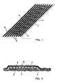
- FIG. 2 is the contact strip 6, as in FIG. 1 is shown arranged in a sectional view on the heating field 4.
- the wavy or meandering conductors of higher conductivity below the steel conductors 8, ie the contact strip, as in FIG. 2 is used opposite the representation of the FIG. 1 turned.
- the contact strip 6 is acted upon by the textile belt 7 and the heating field 4 with its textile substrate 2 and the heating conductors 3 to form a composite via a textile, stitch-forming thread 10 by means of stitching or knitting technique.
- the contact strips 6 are first prepared in the form of textile strips 7 with the two types of conductors 8 and 9, then this contact strip 6 is glued to the underside of the textile tape 7 on the textile substrate 2 for the heating field 4 and thus fixed, then the heating element 3 of the heating field 4, which are preferably formed of carbon fibers, applied by being placed in the predetermined patterns on the substrate 2 and sewn thereto, and at the same time the contact strip 6, which is first fixed to the substrate only was incorporated by means of active technology in the textile substrate 2.
- this surface heating element is very flexible and compliant, not only in the area of the heating field 4, but also in the area of the contact strips 6.
- the two different types of conductors i. on the one hand the steel conductor 8 and on the other hand the conductor 9 of higher conductivity than the steel conductors, in the present example of conductors made of copper or copper wires, ensures that a highly conductive, and suitable for high bending cycle cycles contact band is formed.
- the conductors 8 and 9 from a large number of very thin single filaments, it is achieved that the tape is soft and shows little sign on the reference surface.
Description
Die vorliegende Erfindung betrifft ein flexibles Flächenheizelement, insbesondere für Sitzheizungen gemäß dem Oberbegriff des Anspruchs 1.The present invention relates to a flexible surface heating element, in particular for seat heaters according to the preamble of claim 1.
Weiterhin betrifft die vorliegende Erfindung ein Verfahren zur Herstellung eines flexiblen Flächenheizelements gemäß dem Oberbegriff des Anspruchs 17.Furthermore, the present invention relates to a method for producing a flexible surface heating element according to the preamble of claim 17.
Sohließlich ist die Erfindung gemäß Anspruch 22 auf die Verwendung eines solchen Flächenheizelements gerichtet.Sohließlich the invention is directed according to claim 22 to the use of such a surface heating element.
In Kraftfahrzeugen ist es üblich Sitze elektrisch zu beheizen. Dies wird im allgemeinen dadurch realisiert, dass eine Heizzwischenlage zwischen dem Sitzkern, welcher aus Schaum oder Fasermaterial besteht, und dem Bezug eingebracht wird. Diese Heizzwischenlage wird über einen Kabelanschluss mit dem Bordnetz des Kraftfahrzeuges verbunden. Durch den Stromfluss wird ein elektrischer Leiter erhitzt und gibt Wärme an die Oberfläche des Sitzes ab. Eine Temperaturregelung oder Temperatursteuerung findet üblicherweise mittels elektronischer Steuergeräte statt, die entweder die Temperatur durch einen zusätzlich in die Heizung eingebrachten Temperaturfühler erfassen und die Temperatur durch Ein- und Ausschalten der Stromzuführung konstant halten oder aber mittels einer Zeitsteuerung die zugeführte Leistung begrenzen.In motor vehicles it is common to heat seats electrically. This is generally realized by introducing a heating intermediate layer between the seat core, which is made of foam or fiber material, and the cover. This Heizzwischenlage is connected via a cable connection to the electrical system of the motor vehicle. The current flow heats an electrical conductor and releases heat to the surface of the seat. A temperature control or temperature control usually takes place by means of electronic control units, which either detect the temperature by an additionally introduced into the heater temperature sensor and keep the temperature constant by switching on and off the power supply or limit the supplied power by means of a timer.
Eine besondere Ausführung eines solchen Flächenheizelementes besteht aus zwei sich gegenüberliegenden Kontaktleisten, die im allgemeinen aus metallischen Leitem bestehen und die die Aufgabe haben, die Heizleiter, welche von Kontaktleiste zu Kontaktleiste verlaufen, elektrisch mit Strom zu versorgen. Dies geschieht dadurch, dass die Heizleiter die Kontaktleiter schneiden und mechanisch an diese angepresst sind, so dass ein elektrischer Kontakt entsteht. Es entsteht dadurch eine Parallelschaltung der Heizleiter, wobei durch Auswahl der elektrischen Leitwerte der Heizleiter die Heizleistung eingestellt werden kann.A particular embodiment of such a surface heating element consists of two opposing contact strips, which generally consist of metallic Leitem and have the task of providing the heating conductors, which extend from contact strip to contact strip, electrically supplied with electricity. This happens because the heating conductors cut the contact conductors and are mechanically pressed against them, so that an electrical contact is formed. This results in a parallel connection of the heating element, wherein by selecting the electrical conductivities of the heating element, the heating power can be adjusted.
Solche Flächnheizelemente sind aus der
Bei dieser Art von Sitzheizung müssen die Kontaktleisten relativ zu den Heizleitem einen hohen Strom führen, so dass sich diese dadurch übermäßig stark erwärmen, was nachteilig ist.In this type of seat heating, the contact strips must lead to a high current relative to the Heizleitem so that they heat up excessively, which is disadvantageous.
Dieses Problem wird bei den bekannten Flächenheizelementen dadurch gelöst das die Kontaktleisten aus Kupfer oder Kupferlegierungen bestehen, also Metallen, die hohe Leitwerte besitzen.This problem is solved in the known surface heating elements in that the contact strips made of copper or copper alloys, ie metals that have high conductivities.
Ein weiteres Problem, das solchen Sitzheizungen zugeordnet ist, sind die im Sitz auftretenden, hohen mechanischen Belastungen, die dazu führen können, dass Teile der Kontaktleiste oder ganze Kontaktleisten brechen. Ein teitweises Brechen der Kontaktleisten führt zu Querschnittsverringerungen und damit zu geringeren Leitwerten an der Kontaktleiste im Bereich der Bruchstelle. In Bezug auf den Strom ergeben sich dadurch an der Bruchstelle hohe Verlustleistungen und damit Überhitzungsstellen.Another problem associated with such seat heaters is the high mechanical loads that occur in the seat, which can cause parts of the contact strip or entire contact strips to break. A temporary break of the contact strips leads to cross-sectional reductions and thus to lower conductivities at the contact strip in the area of the break point. With regard to the current, this results in high power losses at the point of breakage and thus overheating points.
Um diese Probleme zu lösen wurden die Leiter von Kontaktleisten wellenförmig ausgelegt, was in der
Alle diese Ausführungsformen tragen immer noch das Risiko eines Bruches der Kontaktleiste bei extremer Faltenbildung des Bezuges. Gerade die Technik, ein solches Flächenheizelement in den Sitzbezug einzunähen, birgt durch die Nähe des Heizelementes zur Sitzoberfläche die Gefahr von Faltenbildung am Bezug und Heizelement und damit auch Faltenbildung und Bruch der Kontaktleiste, auch bei oben genannten Ausführungen.All of these embodiments still carry the risk of breakage of the contact strip with extreme wrinkling of the cover. Especially the technique of sewing such a surface heating element in the seat cover, due to the proximity of the heating element to the seat surface the risk of wrinkles on the cover and heating element and thus wrinkling and breakage of the contact strip, even in the above versions.
Aus der
Aus der
Schließlich beschreibt die
Die Kontaktleiter, die an den Rändern des Heizfelds vorgesehen sind, sind in verschiedenen Ausführungsformen als Kontaktstreifen ausgeführt. Die Kontaktstreifen können in einer Ausführungsform aus einem Trägerband bestehen, auf dem die Kontaktleiter angebracht sind. Auch ist für die Kontaktleiter ein geflochtenes Metallgewirke angegeben. Nach diesem Dokument wird nur eine Leiterart für die Kontaktleiter vorgesehen, nämlich solche aus Kupfer oder solche in Form eines Metallgewirkes.The contact conductors, which are provided at the edges of the heating field, are designed as contact strips in various embodiments. The contact strips may in one embodiment consist of a carrier tape on which the contact conductors are mounted. Also, a braided Metallgewirke is specified for the contact conductor. According to this document, only one type of conductor is provided for the contact conductors, namely those made of copper or those in the form of a metal knit.
Der vorliegenden Erfindung liegt nun die Aufgabe zugrunde, eine Kontaktleiste zu schaffen, die trotz hoher mechanischer Belastung und hohen elektrischen Strömen die Bruchgefahr soweit reduziert, dass damit bestückte Flächenheizelemente sowohl zwischen Bezug und Sitzkem als auch im Bezug eingesetzt werden können, ohne dass die Gefahr einer Überhitzung oder sogar eines Brandes entsteht.The present invention is now based on the object to provide a contact strip that reduces the risk of breakage despite high mechanical load and high electrical currents so far that equipped with surface heating both between reference and Sitzkem and in relation can be used without the risk of Overheating or even a fire arises.
Die Aufgabe des Anmeldungsgegenstands wird durch den Gegenstand des Patentanspruchs 1 gelöst.The object of the subject of the application is solved by the subject-matter of patent claim 1.
Erst in Verbindung mit einem zweiten Leitertyp großer Leitfähigkeit können diese im Kontaktleiter eingesetzt werden, wobei die Anordnung der beiden Leitertypen und die Verbindung untereinander ein ausschlaggebende Rolle spielt.Only in conjunction with a second type of conductor of high conductivity can they be used in the contact conductor, wherein the arrangement of the two types of conductors and the connection with each other plays a decisive role.
Dabei wird die Tatsache genutzt, dass die Funktion der Kontaktleiste auch vollständig dann gegeben ist, wenn der Leiter höherer Leitfähigkeit an einer oder mehreren Stelle(n) unterbrochen ist. An diesen Unterbrechungsstellen tragen ausschließlich die Stahlleiter zur Stromleitung bei. Durch den sehr kurzen Bereich, welcher jeweils durch die Enden der Leiter höherer Leitfähigkeit begrenzt ist, ist die an der Unterbrechungsstelle ent-stehende Verlustleistung so gering, dass ein Brand oder eine spürbare Überhitzung der Oberfläche ausgeschlossen werden kann.The fact is used that the function of the contact strip is also completely given when the conductor of higher conductivity at one or more place (s) is interrupted. At these points of interruption, only the steel conductors contribute to the power line. Due to the very short area, which is limited in each case by the ends of the conductors of higher conductivity, the ent-standing power loss at the point of interruption is so low that a fire or a noticeable overheating of the surface can be excluded.
Besonders kurz kann der Bereich, in dem nur die Stahlleiter den Strom aufnehmen, gehalten werden, indem die Kontaktleiste(n) aus mindestens einem Strang und vorzugsweise mehreren Strängen Stahlleitern besteht (bestehen) und auf der gegenüberliegenden Seite der Stahlleiter mindestens ein Strang und vorzugsweise mehrere wellenförmig verlaufende Stränge von Leitern höherer Leitfähigkeit als die Stahlleiter angeordnet ist bzw. sind, so dass die Verlustleistung besonders gering ist und die Überhitzung nur ein Niveau erreicht, welches weder zum Brand noch zu spürbaren Überhitzungen der Sitzoberfläche führt.The area in which only the steel conductors receive the current can be kept particularly short by the contact strip (s) consisting of at least one strand and preferably several strands of steel conductors and at least one strand on the opposite side of the steel conductors and preferably several undulating strands of conductors of higher conductivity than the steel conductors is or are arranged, so that the power loss is particularly low and the overheating reaches only a level which leads neither to the fire nor to noticeable overheating of the seat surface.
Die Anzahl an Stahlfilamenten, die zu einem Bündel, einen jeweiligen Leiter bildend, zusammengefasst sind, kann zwischen 20 bis 2000 Einzelfilamenten betragen; vorzugsweise sollte die Anzahl 150 bis 500 Einzelfilamenten betragen.The number of steel filaments combined into a bundle forming a respective conductor can be between 20 to 2000 individual filaments; Preferably, the number should be 150 to 500 individual filaments.
Die Dicke der einzelnen Stahlfilamente, die zu einem Bündel zusammengefasst werden, liegt bei 8 bis 15 µm. Die Dicke der einzelnen Filamente der höheren Leitfähigkeit sollte zwischen 50 µm und 100 µm betragen. Diese unterschiedlichen Dicken, zum einen der einzelnen Stahlfilamente, zum anderen der Filamente der höheren Leitfähigkeit, ergeben sich aufgrund der Tatsache, dass Stahlfilamente sehr dünn hergestellt werden können, ohne dass die Fasern brechen. Bevorzugt werden die Querschnitte der einzelnen Stahlfilamente mindestens dreifach kleiner gewählt als die Querschnitte der Filamente der Leiter mit höherer Leitfähigkeit.The thickness of the individual steel filaments, which are combined into a bundle, is 8 to 15 μm. The thickness of the individual filaments of higher conductivity should be between 50 μm and 100 μm. These different thicknesses, on the one hand the individual steel filaments, on the other hand the filaments of higher conductivity, are due to the fact that steel filaments can be made very thin without the fibers breaking. Preferably, the cross sections of the individual steel filaments are selected at least three times smaller than the cross sections of the filaments of the conductors with higher conductivity.
Vorzugsweise sollten die Querschnitte der einzelnen Stahlfilamente mindestens 10 bis 30 mal kleiner sein als die Querschnitte der Filamente der Leiter mit höherer Leitfähigkeit.Preferably, the cross sections of the individual steel filaments should be at least 10 to 30 times smaller than the cross sections of the filaments of the higher conductivity conductors.
Die Leiter höherer Leitfähigkeit verlaufen wellen- oder mäanderförmig, die jeweiligen Stahlleiter kreuzend und mit diesen in Kontakt stehend; dadurch ist gewährleistet, dass die zwei Leiterarten untereinander elektrisch verbunden sind und bei Bruch der Leiter höherer Leitfähigkeit die Fehlstelle lokal begrenzt bleibt und die gebrochenen Leiterenden nicht voneinander wegwandern.The higher conductivity conductors are wavy or meandering, crossing and contacting the respective steel conductors; This ensures that the two types of conductors are electrically connected to each other and in case of breakage of the conductor of higher conductivity, the defect remains locally limited and the broken conductor ends do not migrate away from each other.
Aus Korrosionsschutzgründen sollten die Stahlfilamente durch Edelstahlfilamente gebildet werden. Dagegen werden die Filamente der Leiter mit höherer Leitfähigkeit, aus Kupfer oder Kupferlegierungen, aufgrund des Leitwerts dieses Materials, gebildet.For corrosion protection reasons, the steel filaments should be formed by stainless steel filaments. In contrast, the filaments of the higher conductivity conductors are formed of copper or copper alloys due to the conductance of this material.
Auch können die Filamente der Leiter mit höherer Leitfähigkeit zusätzlich eine Korrosionsschutzschicht aufweisen, die bevorzugt aus Zinn, Silber oder Nickel gebildet ist.In addition, the filaments of the conductors with higher conductivity may additionally have a corrosion protection layer, which is preferably formed from tin, silver or nickel.
Verfahrensgemäß werden bevorzugt die beiden Leiter der Kontaktleiste in das textile Band mittels Wirktechnik eingearbeitet.According to the method, the two conductors of the contact strip are preferably incorporated into the textile tape by means of active technique.
Zum Befestigen der Leiter an dem textilen Band sollten Polyesterfäden oder Polyamidfäden eingesetzt werden, da die textilen Fasern sehr dünn gehalten werden können und die Heizleiter beim Aufliegen auf die Kontaktleiter nur wenig behindern.Polyester threads or polyamide threads should be used to fasten the conductors to the textile band, since the textile fibers can be kept very thin and only slightly hinder the heating conductors when they rest on the contact conductors.
Besonders bevorzugt ist eine Verfahrensweise, bei der die Leiter mittels Nähwirktechnik auf das Band aufgebracht werden; hierbei wird eine Leiterart im Kurz- oder Teilschuss eingebracht, und ausschließlich der/die Polyesterfaden/Polyesterfäden oder der/die Polyamidfaden/Polyamidfäden bildet/bilden die Maschen. Mit dieser Verfahrensweise ist gewährleistet, dass die Leiterarten zueinander vorfixiert sind und sich in weiteren Verfahrensschritten nicht mehr zueinander verschieben können.Particularly preferred is a procedure in which the conductors are applied by means of stitching on the tape; In this case, a ladder type is introduced in the short or partial shot, and only the / the polyester thread / polyester threads or the / the Polyamidfaden / polyamide threads forms / form the stitches. This procedure ensures that the types of conductors are prefixed to one another and can no longer move relative to one another in further method steps.
Um eine hohe Dehnungsfähigkeit und Nachgiebigkeit der Kontaktleisten, die die Stromzuführungen des flexiblen Flächenheizelements bilden, zu erreichen, sollten mindestens die Leiter großen Querschnittes der Kontaktleiste wellenförmig oder mäanderförmig über das Trägerband angeordnet werden, wobei die Wellenachse hierbei der Bandrichtung entspricht.In order to achieve a high extensibility and resilience of the contact strips, which form the power supply lines of the flexible surface heating element, at least the conductors of large cross section of the contact strip should be arranged wave-like or meandering over the carrier tape, wherein the shaft axis in this case corresponds to the tape direction.
Bevorzugt werden Flächenheizelemente, wie sie vorstehend beschrieben sind, als Flächenheizelemente für Sitzheizungen von Fahrzeugen eingesetzt, wo die vorstehend angegebenen Vorteile besonders zum Tragen kommen.Preferably, surface heating elements, as described above, are used as surface heating elements for seat heaters of vehicles, where the above-mentioned advantages are particularly significant.
Weitere Einzelheiten und Merkmale der Erfindung ergeben sich aus der nachfolgenden Beschreibung von Ausführungsbeispielen anhand der Zeichnungen. In der Zeichnung zeigt
- Figur 1
- eine schematische Darstellung einer Kontaktleiste bzw. eines Kontaktbands gemäß der Erfindung, das als Stromzuführung in dem Flächenheizelement eingesetzt wird, wie es in
Figur 3 Figur 2- einen Schnitt durch das flexible Flächenheizelement der
Figur 3 im Bereich einer Kontaktleiste bzw. einem Kontaktband, wie es inFigur 1 dargestellt ist, und zwar quer zu den parallel verlaufenden Leitern, und Figur 3- ein flexibles Flächenheizelement mit schematisch angedeuteten Kontaktleisten an beiden Randbereichen.
- FIG. 1
- a schematic representation of a contact strip or a contact strip according to the invention, which is used as a power supply in the surface heating element, as shown in
FIG. 3 is shown - FIG. 2
- a section through the flexible surface heating of the
FIG. 3 in the area of a contact strip or a contact band, as inFIG. 1 is shown, and transversely to the parallel conductors, and - FIG. 3
- a flexible surface heating element with schematically indicated contact strips on both edge regions.
In
Wie anhand der
In
Um ein Flächenheizelement 1, wie es in
Es ist ersichtlich, dass dieses Flächenheizelement, wie es in den Figuren dargestellt ist, sehr flexibel und nachgiebig ist, und zwar nicht nur im Bereich des Heizfelds 4, sondern auch im Bereich der Kontaktleisten 6. Außerdem ist durch die zwei verschiedenen Leiterarten, d.h. zum einen der Stahlleiter 8 und zum anderen der Leiter 9 höherer Leitfähigkeit als die Stahlleiter, im vorliegenden Beispiel von Leitern aus Kupfer oder Kupferdrähten, gewährleistet, dass ein hoch leitfähiges, und für hohe Biegewechselzyklen geeignetes Kontaktband entsteht. Schließlich wird durch den Aufbau der Leiter 8 und 9 aus einer großen Anzahl von sehr dünnen Einzelfilamenten erreicht, dass das Band weich ist und wenig Abzeichnung an der Bezugsoberfläche zeigt.It can be seen that this surface heating element, as shown in the figures, is very flexible and compliant, not only in the area of the
Claims (22)
- A flexible surface heating element (1), particularly for seat heaters, comprising a flexible carrier material (2), wherein in the portion thereof a heating field (4) of heating conductors (3) is arranged, which are connected electrically conducting to at least one contact strip (6), wherein two types of conductors composed of different material exist in the area of the at least one contact strip (6) and wherein the both types of conductors being electrically interconnected with each other, characterized in that the contact strip (6) is composed of a textile band, having a portion of conductors (8) in the form of steel filaments and a portion of conductors (9) in the form of filaments of a higher conductivity than that of the steel filaments, wherein the conductors (9) of higher conductivity extending wave-shaped or meandering, crossing the respective steel conductors (8) and being in contact with said conductors, and wherein the conductors (9) of higher conductivity extending only above or only under the steel filaments (8), and that the conductors (8, 9) are held by means of textile and/or metallic yarns on the textile band (7), wherein the textile band (7) is connected with the carrier material (2).
- The flexible surface heating element according to claim 1, characterized in that at least individual conductors (8) are formed from a plurality of steel filaments combined to form a bundle.
- The flexible surface heating element according to claim 1 or 2, characterized in that at least individual conductors (9) of the higher conductivity are formed from a plurality of filaments combined to form a bundle.
- The flexible surface heating element according to claim 2, characterized in that the bundle of the steel filaments of the respective conductor (8) is formed from 20 to 2000 individual filaments.
- The flexible surface heating element according to claim 4, characterized in that the bundle of the steel filaments of the respective conductor (8) is formed from 150 to 500 individual filaments.
- The flexible surface heating element according to claim 3, characterized in that the filaments of the respective conductor (9) with the higher conductivity are formed from 20 to 500 individual filaments.
- The flexible surface heating element according to any one of claims 1 to 6, characterized in that the thickness of the individual steel filaments is 8 µm to 15 µm.
- The flexible surface heating element according to any one of claims 1 to 7, characterized in that the thickness of the individual filaments of the higher conductivity is about 50 µm.
- The flexible surface heating element according to any one of claims 1 to 8, characterized in that the cross sections of the individual steel filaments (8) are at least three times smaller than the cross sections of the filaments of the conductors (9) of higher conductivity.
- The flexible surface heating element according to claim 9, characterized in that the cross-sections of the individual steel filaments (8) are at least 10 to 30 times smaller than the cross sections of the filaments of the conductors (9) of higher conductivity.
- The flexible surface heating element according to any one of claims 1 to 10, characterized in that the conductors (8), formed from the steel filaments, extend substantially linearly.
- The flexible surface heating element according to any one of claims 1 to 11, characterized in that either only the steel conductors (8) or only the conductors (9) of higher conductivity are electrically connected to the conductive fibers (3) of the heating field (4).
- The flexible surface heating element according to any one of claims 1 to 12, characterized in that the steel filaments (8) are formed by stainless steel filaments.
- The flexible surface heating element according to any one of claims 1 to 13, characterized in that the filaments of the conductors (9) of higher conductivity are formed from copper or copper alloys.
- The flexible surface heating element according to any one of claims 1 to 14, characterized in that the filaments of the conductors (9) of higher conductivity additionally comprise an anti-corrosion layer.
- The flexible surface heating element according to claim 15, characterized in that the anti-corrosion layer is made from tin, silver or nickel.
- A method for producing a flexible surface heating element (1), particularly a flexible surface heating element for seat heaters, comprising a heating field (4) of heating conductors (3), particularly carbon fibers, which are arranged in the area of a flexible carrier material (2) and which are electrically connected to at least one contact strip (6), wherein two types of conductors composed of different materials exist in the area of the contact strip (6) being electrically interconnected with each other, characterized in that the contact strip (6) is composed in form of a textile band (7) having a portion of conductors (8) in the form of steel filaments and a portion of conductors (9) in the form of filaments of a higher conductivity than that the steel filaments, wherein the conductors (9) of higher conductivity extending wave-shaped or meandering, crossing the respective steel conductors (8) and being in contact with said conductors, and wherein the conductors (9) of higher conductivity extending only above or only under the steel filaments (8), and that the conductors (8, 9) are held by means of textile and/or metallic yarns on the textile band (7), and wherein the textile band (7) is connected with the carrier material (2).
- The method according to claim 17, characterized in that the both conductors (8, 9) of the contact strip (6) are incorporated into the textile band (10) by means of a knitting technique.
- The method according to claim 17, characterized in that polyester yarns or polyamide yarns are used as yarns for fixing the conductors (8, 9) to the textile band (10).
- The method according to claim 17, characterized in that the conductors (8, 9) are applied by means of a sewing/knitting technique to the band (10), at least one type of conductor being incorporated by short or partial weft and the polyester yarn(s) or the polyamide yarn(s) exclusively forming loops.
- The method according to claim 17, characterized in that at least one conductor (9) of the contact strip (6) is arranged in wave-like or meandering fashion along the carrier band (7), the wave axis corresponding to the band direction.
- Use of a surface heating element according to any one of the preceding claims 1 to 16 as a surface heating (1) element for the seat heater of a vehicle seat.
Applications Claiming Priority (1)
| Application Number | Priority Date | Filing Date | Title |
|---|---|---|---|
| DE102005050459A DE102005050459B3 (en) | 2005-10-19 | 2005-10-19 | Surface heating element for seat heater of motor vehicle seat, has conductor of higher conductivity running wave-like and meander-like and intersecting each of multiple steel filaments at several points |
Publications (3)
| Publication Number | Publication Date |
|---|---|
| EP1777992A2 EP1777992A2 (en) | 2007-04-25 |
| EP1777992A3 EP1777992A3 (en) | 2008-03-05 |
| EP1777992B1 true EP1777992B1 (en) | 2013-05-29 |
Family
ID=37547498
Family Applications (1)
| Application Number | Title | Priority Date | Filing Date |
|---|---|---|---|
| EP06017871.2A Active EP1777992B1 (en) | 2005-10-19 | 2006-08-28 | Flexible flat heating element, particularly for seats heating, and the manufacturing method of a flexible heating elements |
Country Status (3)
| Country | Link |
|---|---|
| US (1) | US7705271B2 (en) |
| EP (1) | EP1777992B1 (en) |
| DE (1) | DE102005050459B3 (en) |
Families Citing this family (25)
| Publication number | Priority date | Publication date | Assignee | Title |
|---|---|---|---|---|
| DE102006021649C5 (en) * | 2006-05-08 | 2013-10-02 | W.E.T. Automotive Systems Ag | Flat heating element |
| DE102007051421A1 (en) * | 2007-10-25 | 2009-05-07 | I.G. Bauerhin Gmbh | Heating element for vehicle seats or steering wheels and method for producing the heating element |
| DE102007056465B4 (en) * | 2007-11-22 | 2010-06-02 | I.G. Bauerhin Gmbh | Motor vehicle seat with seat heating |
| TW200925344A (en) * | 2007-12-12 | 2009-06-16 | Everest Textile Co Ltd | Electric heating fabric device |
| DE102008035057B4 (en) | 2008-07-26 | 2023-01-26 | Volkswagen Ag | Textile surface heating element |
| DE102008039840A1 (en) | 2008-08-27 | 2010-03-04 | Sgl Carbon Ag | Stretched carbon fiber yarns for a heater |
| CN103097184B (en) * | 2011-03-07 | 2016-01-20 | 松下知识产权经营株式会社 | Vehicle seat heater |
| CN103460794B (en) | 2011-04-04 | 2016-02-24 | 贝卡尔特公司 | Comprise the heating cable of steel monofilament |
| JP5436491B2 (en) * | 2011-05-20 | 2014-03-05 | 北陸エステアール協同組合 | Planar heating element |
| WO2013050621A2 (en) * | 2011-10-06 | 2013-04-11 | Iee International Electronics & Engineering S.A. | Electrically conductive textiles for occupant sensing and/or heating applications |
| TWI467070B (en) * | 2011-12-16 | 2015-01-01 | Kings Metal Fiber Technologies | Woven electric connection structure |
| KR101504802B1 (en) | 2012-01-31 | 2015-03-30 | 실버레이 주식회사 | Electric conduction planar element with damage prevention function of electric cable |
| DE102013203584B4 (en) * | 2013-03-01 | 2016-01-07 | Beiersdorf Ag | Heating element with flat, heat-generating layer, patch with heating element and method for producing a heating element |
| DE102013226911A1 (en) | 2013-12-20 | 2015-06-25 | Benecke-Kaliko Ag | Electrically heated surface element |
| FI10797U1 (en) * | 2014-12-04 | 2015-03-10 | Wicetec Oy | A conductor joint for connecting a copper conductor |
| US20170066355A1 (en) * | 2015-09-04 | 2017-03-09 | Magna Seating Inc | Vehicle Seat With Improved Thermal Conductivity |
| TWI824186B (en) * | 2015-11-20 | 2023-12-01 | 日商琳得科股份有限公司 | Sheet, heating element and heating device |
| US10442328B2 (en) | 2016-06-21 | 2019-10-15 | Kongsberg Automotive Ab | Assembly, system, and circuit with combined heating and occupancy detecting for a vehicle seat |
| CN108859887A (en) * | 2017-05-08 | 2018-11-23 | 捷温有限责任公司 | heating device |
| EP3442309B1 (en) | 2017-08-07 | 2021-06-30 | Benecke-Kaliko AG | Method for the production of an electrically conductive textile surface element |
| US20220167465A1 (en) * | 2019-02-26 | 2022-05-26 | Iee International Electronics & Engineering S.A. | Flexible and stretchable electric heater based on electrically conductive textile material and method of manufacturing same |
| JP7372467B2 (en) * | 2019-12-20 | 2023-10-31 | ジェンサーム ゲーエムベーハー | heating device |
| US20220097581A1 (en) * | 2020-09-28 | 2022-03-31 | GM Global Technology Operations LLC | Weft knit interdigitated electrodes for automotive interior heating elements |
| US20220314851A1 (en) * | 2021-03-31 | 2022-10-06 | Lear Corporation | Seat support |
| USD1021032S1 (en) * | 2021-12-28 | 2024-04-02 | Shin-Etsu Polymer Co., Ltd. | Heat conducting unit |
Family Cites Families (16)
| Publication number | Priority date | Publication date | Assignee | Title |
|---|---|---|---|---|
| CA977953A (en) * | 1970-04-15 | 1975-11-18 | Charles Davidoff | Metal-containing fibrous material |
| NL7315574A (en) * | 1973-11-14 | 1975-05-16 | Benoit De La Bretoniere Andre | TISSUE. |
| US4581522A (en) * | 1981-10-07 | 1986-04-08 | Intermountain Thermafloor, Inc. | Electrical heating system including a mesh heating element |
| DE4020580A1 (en) * | 1990-06-28 | 1992-01-09 | Ruthenberg Gmbh Waermetechnik | ELECTRIC SURFACE HEATING ELEMENT |
| DE4101290C2 (en) * | 1991-01-17 | 1994-11-03 | Ruthenberg Gmbh Waermetechnik | Electric surface heating element |
| DE4124684A1 (en) * | 1991-07-25 | 1993-01-28 | Bauerhin I G Elektro Tech | Surface electrical heating element e.g. for car seat - has carrier of flexible material into which is set heating element consisting of multiple filaments |
| DE4142774A1 (en) * | 1991-12-23 | 1993-07-01 | Bauerhin I G Elektro Tech | SURFACE HEATING ELEMENT AND METHOD FOR THE PRODUCTION THEREOF |
| DE4312622A1 (en) * | 1993-04-19 | 1994-10-20 | Bauerhin I G Elektro Tech | Planar heating element on the basis of multiple filaments |
| US5503887A (en) * | 1995-01-04 | 1996-04-02 | Northrop Grumman Corporation | Conductive woven material and method |
| US5824996A (en) * | 1997-05-13 | 1998-10-20 | Thermosoft International Corp | Electroconductive textile heating element and method of manufacture |
| JP2001021245A (en) * | 1999-07-09 | 2001-01-26 | Irie Koken Kk | Material and device for cold storage |
| DE10066130B4 (en) * | 2000-12-22 | 2008-01-03 | W.E.T. Automotive Systems Ag | Textile heating device |
| DE10206336B4 (en) * | 2002-02-14 | 2004-10-07 | Bauerhin, I.G. | Electric heating element for seat heaters and steering wheel heaters |
| EP1362940A1 (en) * | 2002-05-13 | 2003-11-19 | N.V. Bekaert S.A. | Electrically conductive yarn comprising metal fibers |
| TWI257822B (en) * | 2003-09-19 | 2006-07-01 | Tex Ray Ind Co Ltd | Flexible electro-heating apparatus and fabrication thereof |
| US7064299B2 (en) * | 2003-09-30 | 2006-06-20 | Milliken & Company | Electrical connection of flexible conductive strands in a flexible body |
-
2005
- 2005-10-19 DE DE102005050459A patent/DE102005050459B3/en not_active Expired - Fee Related
-
2006
- 2006-08-28 EP EP06017871.2A patent/EP1777992B1/en active Active
- 2006-10-16 US US11/581,313 patent/US7705271B2/en not_active Expired - Fee Related
Also Published As
| Publication number | Publication date |
|---|---|
| EP1777992A3 (en) | 2008-03-05 |
| EP1777992A2 (en) | 2007-04-25 |
| US20080099458A1 (en) | 2008-05-01 |
| DE102005050459B3 (en) | 2007-03-15 |
| US7705271B2 (en) | 2010-04-27 |
Similar Documents
| Publication | Publication Date | Title |
|---|---|---|
| EP1777992B1 (en) | Flexible flat heating element, particularly for seats heating, and the manufacturing method of a flexible heating elements | |
| EP1835786B1 (en) | Planar heating element and process for manufacturing a planar heating element | |
| DE102006026047B4 (en) | Heating element, seat and vehicle with such | |
| DE102006021649C5 (en) | Flat heating element | |
| DE4101290C2 (en) | Electric surface heating element | |
| EP0532468B1 (en) | Electrical heating element | |
| DE10066130B4 (en) | Textile heating device | |
| EP1961264B1 (en) | Flat heating element | |
| DE10206336B4 (en) | Electric heating element for seat heaters and steering wheel heaters | |
| EP0226692B1 (en) | Heating conductor connection between electrically heated seat and backrest surfaces for heating seats of vehicles; the said surfaces are separated by an anchoring groove, which is provided for in the upholstery core | |
| WO2005089019A2 (en) | Flat heating element | |
| DE4020580A1 (en) | ELECTRIC SURFACE HEATING ELEMENT | |
| WO2007048520A2 (en) | Planar heating element for a motor vehicle seat | |
| EP2329682A2 (en) | Electrically conductive polymer ribbon and polymer tissue on the basis of electrically conductive polymer fibers, yarns, threads and cords for areal heating elements | |
| EP1815717B1 (en) | Method for the production of a textile surface-heating element | |
| DE4142774A1 (en) | SURFACE HEATING ELEMENT AND METHOD FOR THE PRODUCTION THEREOF | |
| EP0706747A1 (en) | Surface heating element | |
| DE102008034815A1 (en) | Electrical surface heating element is sectionally formed as heating knitted fabric with flexible electrical heat conductor, where loop of heating knitted fabric, forms multiple knitting rows that are interlaced with each other | |
| DE102004045875A1 (en) | Element for heating surfaces contacted by passengers of a vehicle incorporates a zone with heater wires, wires for bringing electricity to the heater wires, and a contact zone for these wires | |
| DE102009003867A1 (en) | Electrically conductive polymer ribbon and polymer tissue combination for producing e.g. areal heating element to heat wall, has yarns with electrically non-conductive polymer, natural or monofilament fibers formed as elastic fibers | |
| DE102007019843B3 (en) | Electrical seat heater for heating surface of seat i.e. passenger car-seat, has plastic-foil strip running between segments along electrical conductor, where strip is made of polyimide or PET and is in heat conducting contact with conductor | |
| DE102019103935B4 (en) | Heating insert in the form of a knitted spacer section and a heatable interior component | |
| DE202006008796U1 (en) | Flat heating element | |
| DE102008035057B4 (en) | Textile surface heating element | |
| DE202006004033U1 (en) | Heatable fabric as for floor coverings has spaced electrically conductive warp threads and a weft of resistive heating material with insulative cover except at contact points |
Legal Events
| Date | Code | Title | Description |
|---|---|---|---|
| PUAI | Public reference made under article 153(3) epc to a published international application that has entered the european phase |
Free format text: ORIGINAL CODE: 0009012 |
|
| AK | Designated contracting states |
Kind code of ref document: A2 Designated state(s): AT BE BG CH CY CZ DE DK EE ES FI FR GB GR HU IE IS IT LI LT LU LV MC NL PL PT RO SE SI SK TR |
|
| AX | Request for extension of the european patent |
Extension state: AL BA HR MK YU |
|
| PUAL | Search report despatched |
Free format text: ORIGINAL CODE: 0009013 |
|
| AK | Designated contracting states |
Kind code of ref document: A3 Designated state(s): AT BE BG CH CY CZ DE DK EE ES FI FR GB GR HU IE IS IT LI LT LU LV MC NL PL PT RO SE SI SK TR |
|
| AX | Request for extension of the european patent |
Extension state: AL BA HR MK YU |
|
| 17P | Request for examination filed |
Effective date: 20080526 |
|
| 17Q | First examination report despatched |
Effective date: 20080722 |
|
| AKX | Designation fees paid |
Designated state(s): DE FR GB SE |
|
| GRAJ | Information related to disapproval of communication of intention to grant by the applicant or resumption of examination proceedings by the epo deleted |
Free format text: ORIGINAL CODE: EPIDOSDIGR1 |
|
| GRAP | Despatch of communication of intention to grant a patent |
Free format text: ORIGINAL CODE: EPIDOSNIGR1 |
|
| GRAP | Despatch of communication of intention to grant a patent |
Free format text: ORIGINAL CODE: EPIDOSNIGR1 |
|
| GRAS | Grant fee paid |
Free format text: ORIGINAL CODE: EPIDOSNIGR3 |
|
| GRAA | (expected) grant |
Free format text: ORIGINAL CODE: 0009210 |
|
| RBV | Designated contracting states (corrected) |
Designated state(s): FR GB SE |
|
| REG | Reference to a national code |
Ref country code: DE Ref legal event code: R108 |
|
| AK | Designated contracting states |
Kind code of ref document: B1 Designated state(s): FR GB SE |
|
| REG | Reference to a national code |
Ref country code: GB Ref legal event code: FG4D Free format text: NOT ENGLISH |
|
| REG | Reference to a national code |
Ref country code: DE Ref legal event code: R108 Effective date: 20130515 |
|
| REG | Reference to a national code |
Ref country code: SE Ref legal event code: TRGR |
|
| PLBE | No opposition filed within time limit |
Free format text: ORIGINAL CODE: 0009261 |
|
| STAA | Information on the status of an ep patent application or granted ep patent |
Free format text: STATUS: NO OPPOSITION FILED WITHIN TIME LIMIT |
|
| GBPC | Gb: european patent ceased through non-payment of renewal fee |
Effective date: 20130829 |
|
| 26N | No opposition filed |
Effective date: 20140303 |
|
| PG25 | Lapsed in a contracting state [announced via postgrant information from national office to epo] |
Ref country code: GB Free format text: LAPSE BECAUSE OF NON-PAYMENT OF DUE FEES Effective date: 20130829 |
|
| REG | Reference to a national code |
Ref country code: FR Ref legal event code: PLFP Year of fee payment: 11 |
|
| REG | Reference to a national code |
Ref country code: FR Ref legal event code: PLFP Year of fee payment: 12 |
|
| REG | Reference to a national code |
Ref country code: FR Ref legal event code: PLFP Year of fee payment: 13 |
|
| PGFP | Annual fee paid to national office [announced via postgrant information from national office to epo] |
Ref country code: SE Payment date: 20230823 Year of fee payment: 18 Ref country code: FR Payment date: 20230824 Year of fee payment: 18 |