EP1777801A2 - Elektrische Stromversorgungsvorrichtung für eine Bohrlochmessungsanordnung - Google Patents
Elektrische Stromversorgungsvorrichtung für eine Bohrlochmessungsanordnung Download PDFInfo
- Publication number
- EP1777801A2 EP1777801A2 EP06026580A EP06026580A EP1777801A2 EP 1777801 A2 EP1777801 A2 EP 1777801A2 EP 06026580 A EP06026580 A EP 06026580A EP 06026580 A EP06026580 A EP 06026580A EP 1777801 A2 EP1777801 A2 EP 1777801A2
- Authority
- EP
- European Patent Office
- Prior art keywords
- power supply
- power
- tools
- storage means
- capacitor
- Prior art date
- Legal status (The legal status is an assumption and is not a legal conclusion. Google has not performed a legal analysis and makes no representation as to the accuracy of the status listed.)
- Withdrawn
Links
Images


Classifications
-
- H—ELECTRICITY
- H02—GENERATION; CONVERSION OR DISTRIBUTION OF ELECTRIC POWER
- H02M—APPARATUS FOR CONVERSION BETWEEN AC AND AC, BETWEEN AC AND DC, OR BETWEEN DC AND DC, AND FOR USE WITH MAINS OR SIMILAR POWER SUPPLY SYSTEMS; CONVERSION OF DC OR AC INPUT POWER INTO SURGE OUTPUT POWER; CONTROL OR REGULATION THEREOF
- H02M3/00—Conversion of DC power input into DC power output
- H02M3/02—Conversion of DC power input into DC power output without intermediate conversion into AC
- H02M3/04—Conversion of DC power input into DC power output without intermediate conversion into AC by static converters
- H02M3/06—Conversion of DC power input into DC power output without intermediate conversion into AC by static converters using resistors or capacitors, e.g. potential divider
- H02M3/07—Conversion of DC power input into DC power output without intermediate conversion into AC by static converters using resistors or capacitors, e.g. potential divider using capacitors charged and discharged alternately by semiconductor devices with control electrode, e.g. charge pumps
-
- G—PHYSICS
- G01—MEASURING; TESTING
- G01V—GEOPHYSICS; GRAVITATIONAL MEASUREMENTS; DETECTING MASSES OR OBJECTS; TAGS
- G01V11/00—Prospecting or detecting by methods combining techniques covered by two or more of main groups G01V1/00 - G01V9/00
- G01V11/002—Details, e.g. power supply systems for logging instruments, transmitting or recording data, specially adapted for well logging, also if the prospecting method is irrelevant
-
- G—PHYSICS
- G01—MEASURING; TESTING
- G01V—GEOPHYSICS; GRAVITATIONAL MEASUREMENTS; DETECTING MASSES OR OBJECTS; TAGS
- G01V3/00—Electric or magnetic prospecting or detecting; Measuring magnetic field characteristics of the earth, e.g. declination, deviation
- G01V3/18—Electric or magnetic prospecting or detecting; Measuring magnetic field characteristics of the earth, e.g. declination, deviation specially adapted for well-logging
- G01V3/26—Electric or magnetic prospecting or detecting; Measuring magnetic field characteristics of the earth, e.g. declination, deviation specially adapted for well-logging operating with magnetic or electric fields produced or modified either by the surrounding earth formation or by the detecting device
Definitions
- the present invention relates to downhole measurement assemblies and more particularly to the electrical power supply arrangement for such assemblies.
- the oil and gas industry employs a variety of information gathering downhole tools during exploration and drilling of wells. These tools provide such information as hole inclination and azimuth, temperature, radioactivity, or resistivity. These tools are encased in non-magnetic stainless steel cylindrical pressure cases. By their nature, these tools have a large length to diameter ratio. The number of tools that have been introduced over the years has increased. Each tool is aligned serially down the drill string, and power is connected to each in parallel on a bus, which also allows communication between the tools and the transmission of signals to the surface. Traditionally, the pressure case of each tool is grounded and is the return path for DC current.
- the directional measurement tool was always the one furthest down the hole and part of the directional measurement tool is an array of fluxgate magnetometers situated at the bottom of the tool in a module known as the stack. These magnetometers respond to the earth's magnetic field. Recently, other tools have been placed below the directional package and the power required by such tools results in current flowing in wire which passes the magnetometers and which in turn generates an electromagnetic field which causes errors in the readings produced by the magnetometers.
- the pressure cases of the downhole tools have always been grounded and connected to the system zero volts. This means that if conventional current carrying conductors are replaced in the region of the magnetometers by say a twisted pair or a coaxial cable, but otherwise the electrical arrangements remain unaltered, the current in the two conductors of the twisted pair or coaxial cable will be unbalanced as some current will flow through the parallel path of the pressure cases. In fact, most of the current will flow through the pressure case as it is a much better conductor.
- the present invention provides a downhole measurement assembly comprising a metal casing housing a plurality of tool sections, one of which includes a detector sensitive to a magnetic field, and a DC power supply for said tool sections, the power supply and the tool sections being electrically connected to the casing, characterised in that the power supply is connected to at least one tool section via a switching circuit and a conductor arrangement, the switching circuit comprising a capacitor, a plurality of switches and control means operative to alternately charge the capacitor from the DC supply and discharge the capacitor through said at least one tool section using the conductor arrangement so as to inhibit the generation of an electro-magnetic field in the conductor arrangement between the capacitor and the said at least one tool.
- FIG 1 shows a diagrammatic representation of a downhole measurement assembly 1 which comprises a plurality of individual tools 3 encased in non-magnetic stainless steel cylindrical pressure cases which are represented by the conductor 2 and which are mechanically and electrically connected together and also grounded.
- the tools 3 are supplied with DC power from a power supply 4 one side of which is also grounded.
- a stack 5 which includes an array of fluxgate magnetometers is located towards the bottom of the assembly 1 below the individual tools 3 but in this case other tools represented by the block 7 are shown in a position on the other side of the stack 5 from the power supply 4. This means that current for the other tools 7 has to be carried by conductors past the stack 5 and this in turn results in the generation of electromagnetic fields in the region of the stack 5 which causes in the output from the stack 5 to be inaccurate.
- the present invention proposes to use a twisted pair or coaxial cable for the current carrying conductors but which allows the pressure cases to be electrically connected together in such a manner that they carry no current. This is achieved by utilising a capacitor connected by a switching network as will be explained in relation to Fig 2.
- one side of the DC supply 4 is connected to the pressure casing 1a of the downhole measurement assembly which is in turn grounded.
- a capacitor 20 is connected between the poles of a two-pole electronic changeover switch which in one position of the switch accumulates charge from the supply and, when the switch is changed over to its other position, allows the capacitor to transfer its charge to one or more downhole tools which are represented by the load 24. It can be seen that although the grounds are connected, no current can flow between them. Thus, all the current delivered to the downhole tools represented by the load 24 must flow in the conductors 25 and 26 connected between the electronic changeover switch 22 and the downhole tools.
- conductors 25 and 26 thus carry the same current but in opposite directions and can be a twisted pair or coaxial cable which can be routed past the magnetometers in the stack without causing electromagnetic interference.
- the changeover switch position is reversed quickly, the effect is enhanced and it is preferred to reverse the switch 22 several thousand times a second.
- Fig 3 shows an improved arrangement of the circuit shown in Fig 2.
- the improved arrangement employs two capacitors 20a and 20b each provided with its own two-pole electronic changeover switch 22a and 22b respectively. With this arrangement, when one capacitor is charging, the other is discharging. This arrangement is more efficient and reduces the ripple voltage between the conductors. This is an important consideration as the conductor 25 is also used as a communications bus in many downhole tool arrangements.
- Fig 4 shows a more practical circuit diagram of the circuit shown in Fig 3 and in Fig 4 the two-pole changeover switches have been replaced by semiconductor switches in the form of MOSFETs. It is preferred to use P-channel MOSFETs for switches SW1 to SW4 and N-channel MOSFETs for switches SW5 to SW8. Although it is not shown in Fig 4, an oscillator is provided in order to drive the MOSFET switches.
- the positive pole of the DC power supply 4 to the capacitor 20a is via MOSFET switch SW1 when closed and the other side of capacitor 20a is connected to the negative terminal of the DC power supply 4 via the MOSFET switch SW5. In this way, capacitor 20a charges.
- capacitor 20b is connected to and discharges into the load via the closed MOSFET switches SW4 and SW8.
- the switches SW1, SW5, SW4, and SW8 are opened and the switches SW2, SW6 close which allows the capacitor 20a to discharge through the load while the MOSFET switches SW3 and SW7 are also closed to allow the capacitor 20b to be charged from the power supply 4.
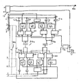
- Figs 5a and 5b when combined at conductors A-J show a block diagram of a practical circuit diagram for implementing the arrangement shown in Fig 4.
- the same component numbers and designations are used in Figs 5a and 5b as are used in Fig 4 and consequently a detailed description of the operation of Fig 5 will not be given.
- the oscillator is now shown and represented by the reference numeral 50. In the present example, it operates at about 53KHz and controls the MOSFETs SW1 to SW8.
- the frequency is not particularly critical but operation has been found to be optimal with a frequency in the region 50KHz to 65KHz.
- the current taken by it is approximately 16 mA. This is due to the current required by the oscillator and amplifier and the current required to switch the MOSFETs, some of which have a gate capacitance of up to 1.5 nF. When it is merely required to pass current past the stack without the need for preventing magnetic interference, current can be saved by turning off the oscillator, in which case the upper and lower switches are short circuit.
- An on/off switch 51 in the form of a transistor is provided for this purpose. When a logic 1 from a control circuit 52 is applied to the gate of the transistor it is turned on and provides power to the oscillator. A logic 0 turns the transistor off and oscillation ceases.
- the output of the oscillator 50 is fed to a primary winding of a transformer 53 which has two centre-tapped secondary windings.
- the upper secondary of the transformer 53 then simply acts as a short circuit to connect the gates of the upper MOSFETS IC2-IC5 through their networks to ground via a resistor (R21) connected to the centre tap turning them on.
- the lower MOSFETs IC6-IC9 are turned on by the lower secondary.
- the output from the circuit shown in Fig 5 is taken from the output terminals 55a and 55b which can be suitable for connection to a twisted pair of wires or a coaxial cable.
- the operational cycle is as follows:
- the charging path from the positive to capacitor 20a is from an input socket 51 to transformers T3 to inductor T1 to IC2/D2 to IC2/S2 to IC2/S1 to IC2/D1 to C20a.
- the return path from the lower end of capacitor 20a is IC9/D1 to IC9/S1 to IC9/S2 to IC9/D1 to inductor T1 to socket 51.
- Capacitor 20a is charged up when the MOSFETs in IC2 and IC9 are switched on.
- capacitor 20b When capacitor 20a is charging up, capacitor 20b is discharging into the load via IC4, IC6, inductor T4 and terminals 55a and 55b.
- the discharge path for capacitor 20a is via IC5, IC8, inductor T4 and terminals 55a and 55b.
- capacitor 20a When capacitor 20a is discharging, capacitor 20b is being charged.
- the charge path for capacitor 20b is similar to that for capacitor 20a but via IC3 and IC7.
- the transformer secondaries switch the MOSFETs on and off in the correct sequence to charge and discharge the capacitors 20a and 20b.
- MOSFET When the gate of a P-Channel MOSFET is negative with respect to its source, then that MOSFET is turned on.
- the upper MOSFETs, IC2, IC5, IC3 and IC4 are dual P-channel devices.
- MOSFETs IC9, IC8, IC7 and IC4 are dual N-channel devices.
- the output transformer 53 from the oscillator 50 has two centre tapped secondaries. One secondary controls the P-channel devices. The other secondary controls the N-channel devices. To save space, only the operation of the P-channel devices will be described.
- Each of the sources is connected to the centre tap secondary through a 100Nf capacitor (C2, C5, C3 and C4).
- the capacitor gives DC isolation, but allows AC to pass through. If they were not there, then all the MOSFET sources would be connected together, rendering the circuit non-operational.
- the upper half of the top secondary winding drives the gates of IC5 and IC3, while the lower half of the top secondary winding drives the gates of IC2 and IC4.
- the gate drive to the MOSFETs is via drive circuits 62-69 each of which consists of a diode and resistor connected in parallel.
- the components compensate for a difference between the turn-on and turn-off delays in the MOSFETs. These delays, were they to occur, would mean that some MOSFETs are turned on for a short time when they should be turned off. The effect would be a small amount of ground current resulting in an imbalance in the currents in the twisted pair or co-axial cable.
- This circuit has been designed to operate over a wide temperature range up to 165°C and has been found to perform satisfactorily.
- Fig 6 is a more detailed arrangement of the circuit shown in Fig 4 and indicates the signal communication through the circuit.
- the type of communication we are dealing with is where a signal is superimposed on the supply line. It is fed into transmitter/receivers through a transformer. Referring to Fig 6, C5 and C17 act as reservoir capacitors, which in conjunction with the inductors T1 and T4, reduce the switching spikes and ripple. The main path for the communication is via C18. A parallel and very necessary path is between the two windings of T3. This wound component acts as both a transformer for communications and also as a dual choke to further reduce the switching spikes and ripple. The two windings of T1 share the same core, but T1 is not a transformer, which is why the two windings are shown separate from each other. The same applies to T4.
- the core shared by the two wind of each inductor been omitted from the figure for clarity purposes.
- the reason for sharing the same core is that the net dc flux is zero due to cancellation. This enables the size of the component to be kept small and prevents saturation, particularly at high temperature.
Landscapes
- Engineering & Computer Science (AREA)
- Life Sciences & Earth Sciences (AREA)
- Physics & Mathematics (AREA)
- Remote Sensing (AREA)
- Geophysics (AREA)
- General Physics & Mathematics (AREA)
- General Life Sciences & Earth Sciences (AREA)
- Power Engineering (AREA)
- Electromagnetism (AREA)
- Environmental & Geological Engineering (AREA)
- Geology (AREA)
- Geophysics And Detection Of Objects (AREA)
- Cable Transmission Systems, Equalization Of Radio And Reduction Of Echo (AREA)
- Investigating Or Analyzing Materials By The Use Of Magnetic Means (AREA)
- Arrangements For Transmission Of Measured Signals (AREA)
- Measurement Of Length, Angles, Or The Like Using Electric Or Magnetic Means (AREA)
Applications Claiming Priority (2)
| Application Number | Priority Date | Filing Date | Title |
|---|---|---|---|
| GB0303875A GB0303875D0 (en) | 2003-02-19 | 2003-02-19 | Electrical power supply arrangement for a downhole measurement assembly |
| EP20040712097 EP1595166A2 (de) | 2003-02-19 | 2004-02-18 | Elektrische stromversorgungsvorrichtung für eine bohrlochmessungsanordnung |
Related Parent Applications (2)
| Application Number | Title | Priority Date | Filing Date |
|---|---|---|---|
| EP20040712097 Division EP1595166A2 (de) | 2003-02-19 | 2004-02-18 | Elektrische stromversorgungsvorrichtung für eine bohrlochmessungsanordnung |
| EP04712097.7 Division | 2004-02-18 |
Publications (2)
| Publication Number | Publication Date |
|---|---|
| EP1777801A2 true EP1777801A2 (de) | 2007-04-25 |
| EP1777801A3 EP1777801A3 (de) | 2011-03-16 |
Family
ID=9953343
Family Applications (2)
| Application Number | Title | Priority Date | Filing Date |
|---|---|---|---|
| EP20060026580 Withdrawn EP1777801A3 (de) | 2003-02-19 | 2004-02-18 | Elektrische Stromversorgungsvorrichtung für eine Bohrlochmessungsanordnung |
| EP20040712097 Withdrawn EP1595166A2 (de) | 2003-02-19 | 2004-02-18 | Elektrische stromversorgungsvorrichtung für eine bohrlochmessungsanordnung |
Family Applications After (1)
| Application Number | Title | Priority Date | Filing Date |
|---|---|---|---|
| EP20040712097 Withdrawn EP1595166A2 (de) | 2003-02-19 | 2004-02-18 | Elektrische stromversorgungsvorrichtung für eine bohrlochmessungsanordnung |
Country Status (8)
| Country | Link |
|---|---|
| US (2) | US20060232138A1 (de) |
| EP (2) | EP1777801A3 (de) |
| AU (1) | AU2004213958B2 (de) |
| BR (1) | BRPI0406205A (de) |
| CA (1) | CA2494170C (de) |
| GB (1) | GB0303875D0 (de) |
| NO (1) | NO20052091L (de) |
| WO (1) | WO2004075369A2 (de) |
Cited By (1)
| Publication number | Priority date | Publication date | Assignee | Title |
|---|---|---|---|---|
| US11085271B2 (en) | 2017-03-31 | 2021-08-10 | Metrol Technology Ltd. | Downhole power delivery |
Families Citing this family (11)
| Publication number | Priority date | Publication date | Assignee | Title |
|---|---|---|---|---|
| GB0303875D0 (en) * | 2003-02-19 | 2003-03-26 | Halliburton Man Ltd | Electrical power supply arrangement for a downhole measurement assembly |
| CN101689801A (zh) * | 2007-06-13 | 2010-03-31 | 半导体元件工业有限责任公司 | 电荷泵控制器及其方法 |
| US9856722B2 (en) | 2014-03-14 | 2018-01-02 | General Electric Company | Methods and systems for controlling voltage switching |
| US10481296B2 (en) * | 2014-10-22 | 2019-11-19 | Hallibunon Energy Services, Inc. | Magnetic sensor correction for field generated from nearby current |
| CA2962194C (en) * | 2014-11-12 | 2019-06-04 | Halliburton Energy Services, Inc. | Well detection using induced magnetic fields |
| GB2535236A (en) * | 2015-02-16 | 2016-08-17 | Ge Oil & Gas Uk Ltd | Retrofit power switching and repeating module |
| US9893631B2 (en) * | 2015-09-23 | 2018-02-13 | Toyota Motor Engineering & Manufacturing North America, Inc. | Non-isolated DC-DC conversion circuit configured for capacitive and magnetic power transfer |
| WO2017123202A1 (en) * | 2016-01-12 | 2017-07-20 | Halliburton Energy Services, Inc. | Downhole control and sensing system |
| US10753191B2 (en) | 2016-06-28 | 2020-08-25 | Baker Hughes, A Ge Company, Llc | Downhole tools with power utilization apparatus during flow-off state |
| US11025059B2 (en) | 2016-10-31 | 2021-06-01 | Baker Hughes Oilfield Operations Llc | Switch systems for controlling conduction of multi-phase current |
| JP7114506B2 (ja) * | 2019-02-21 | 2022-08-08 | 公益財団法人鉄道総合技術研究所 | コンデンサおよび絶縁回路 |
Family Cites Families (11)
| Publication number | Priority date | Publication date | Assignee | Title |
|---|---|---|---|---|
| US3459956A (en) * | 1966-08-25 | 1969-08-05 | Schlumberger Technology Corp | Power supply system for well logging |
| FR207196A (de) * | 1969-12-22 | |||
| JPS5814224A (ja) * | 1981-07-17 | 1983-01-27 | Nippon Gakki Seizo Kk | 電源回路 |
| JPH02146955A (ja) * | 1988-08-30 | 1990-06-06 | Michiko Naito | 静電トランス |
| US5596489A (en) * | 1994-01-14 | 1997-01-21 | Intel Corporation | Capacitive transformer having a switch responsive to clock signals |
| US6088294A (en) * | 1995-01-12 | 2000-07-11 | Baker Hughes Incorporated | Drilling system with an acoustic measurement-while-driving system for determining parameters of interest and controlling the drilling direction |
| US5744877A (en) * | 1997-01-13 | 1998-04-28 | Pes, Inc. | Downhole power transmission system |
| JP2002531049A (ja) * | 1998-11-19 | 2002-09-17 | インフィネオン テクノロジース アクチエンゲゼルシャフト | 電力供給装置および該電力供給装置を備えた回路 |
| SE515800C2 (sv) * | 1999-01-20 | 2001-10-08 | Ericsson Telefon Ab L M | Anordning och förfarande för att snabbstarta en sinusoscillator |
| US6392317B1 (en) * | 2000-08-22 | 2002-05-21 | David R. Hall | Annular wire harness for use in drill pipe |
| GB0303875D0 (en) | 2003-02-19 | 2003-03-26 | Halliburton Man Ltd | Electrical power supply arrangement for a downhole measurement assembly |
-
2003
- 2003-02-19 GB GB0303875A patent/GB0303875D0/en not_active Ceased
-
2004
- 2004-02-18 EP EP20060026580 patent/EP1777801A3/de not_active Withdrawn
- 2004-02-18 US US10/546,056 patent/US20060232138A1/en not_active Abandoned
- 2004-02-18 EP EP20040712097 patent/EP1595166A2/de not_active Withdrawn
- 2004-02-18 CA CA 2494170 patent/CA2494170C/en not_active Expired - Lifetime
- 2004-02-18 AU AU2004213958A patent/AU2004213958B2/en not_active Ceased
- 2004-02-18 BR BRPI0406205 patent/BRPI0406205A/pt not_active IP Right Cessation
- 2004-02-18 WO PCT/GB2004/000629 patent/WO2004075369A2/en not_active Ceased
-
2005
- 2005-04-29 NO NO20052091A patent/NO20052091L/no not_active Application Discontinuation
-
2009
- 2009-05-26 US US12/472,152 patent/US7928605B2/en not_active Expired - Fee Related
Cited By (2)
| Publication number | Priority date | Publication date | Assignee | Title |
|---|---|---|---|---|
| US11085271B2 (en) | 2017-03-31 | 2021-08-10 | Metrol Technology Ltd. | Downhole power delivery |
| US11732553B2 (en) | 2017-03-31 | 2023-08-22 | Metrol Technology Ltd. | Downhole power delivery |
Also Published As
| Publication number | Publication date |
|---|---|
| WO2004075369A2 (en) | 2004-09-02 |
| EP1777801A3 (de) | 2011-03-16 |
| US7928605B2 (en) | 2011-04-19 |
| CA2494170C (en) | 2013-11-19 |
| US20060232138A1 (en) | 2006-10-19 |
| GB0303875D0 (en) | 2003-03-26 |
| WO2004075369A3 (en) | 2005-03-24 |
| NO20052091L (no) | 2005-04-29 |
| BRPI0406205A (pt) | 2005-08-09 |
| AU2004213958B2 (en) | 2009-07-02 |
| CA2494170A1 (en) | 2004-09-02 |
| AU2004213958A1 (en) | 2004-09-02 |
| EP1595166A2 (de) | 2005-11-16 |
| US20090243399A1 (en) | 2009-10-01 |
Similar Documents
| Publication | Publication Date | Title |
|---|---|---|
| US7928605B2 (en) | Electrical power supply arrangement for a downhole measurement assembly | |
| US6914538B2 (en) | High-power well logging method and apparatus | |
| US8264369B2 (en) | Intelligent electrical power distribution system | |
| EP0667067B1 (de) | Übertragungsnetzwerk und filter hierfür | |
| EP0100098B1 (de) | Gleichstromumformer für Fernstromversorgung | |
| US7525264B2 (en) | Shunt regulation apparatus, systems, and methods | |
| RU2040691C1 (ru) | Система передачи электрической энергии и информации в колонне стыкующихся труб | |
| EP2806435A2 (de) | Trenntransformator zur Verwendung in isoliertem Gleichstrom-zu-Gleichstrom-Schaltnetzteil | |
| CA2955418C (en) | Electrical cable link apparatus and electrical cable system comprising the apparatus | |
| US7081831B2 (en) | Time-domain signal cancellation in downhole telemetry systems | |
| US7166933B2 (en) | Submarine power feeding branching device for submarine power feeding system having submarine feeding cables arranged in mesh pattern | |
| EP0410526B1 (de) | Generator zum Erzeugen einer elektrischen Spannung | |
| EP1650401A2 (de) | Hochleistungsverfahren und Gerät für Bohrlochmessung | |
| US6426610B1 (en) | Controlled ferroresonant constant current source | |
| US7193397B2 (en) | Voltage converter | |
| US6633493B2 (en) | Inherently short-circuit resistant power distribution system | |
| EP0400271A2 (de) | Hochspannungsgenerator-Einrichtung vom Typ eines in mehrfachen Stufen isolierenden Transformators | |
| EP0425574A1 (de) | Transformator mit symmetrischen gegentakt-windungen | |
| SU1330596A1 (ru) | Устройство дл электроразведки (его варианты) | |
| SU1078511A2 (ru) | Магнитна антенна-индукционный кабелеискатель | |
| SU619885A2 (ru) | Устройство дл передачи высокочастотной информации и питани скважинного радиоактивного каротажа | |
| JPH04244783A (ja) | 多段式絶縁変圧器型高電圧発生装置 | |
| CH660541A5 (en) | Device for compensating for network impedances for a system for transmitting audio-frequency signals via electrical power supply lines |
Legal Events
| Date | Code | Title | Description |
|---|---|---|---|
| PUAI | Public reference made under article 153(3) epc to a published international application that has entered the european phase |
Free format text: ORIGINAL CODE: 0009012 |
|
| AC | Divisional application: reference to earlier application |
Ref document number: 1595166 Country of ref document: EP Kind code of ref document: P |
|
| AK | Designated contracting states |
Kind code of ref document: A2 Designated state(s): DE FR GB |
|
| AX | Request for extension of the european patent |
Extension state: AL LT LV MK |
|
| PUAL | Search report despatched |
Free format text: ORIGINAL CODE: 0009013 |
|
| RIC1 | Information provided on ipc code assigned before grant |
Ipc: H02M 3/07 20060101ALI20110127BHEP Ipc: G01V 1/52 20060101ALI20110127BHEP Ipc: G01V 11/00 20060101AFI20110127BHEP |
|
| AK | Designated contracting states |
Kind code of ref document: A3 Designated state(s): DE FR GB |
|
| AX | Request for extension of the european patent |
Extension state: AL LT LV MK |
|
| 17P | Request for examination filed |
Effective date: 20110511 |
|
| AKX | Designation fees paid |
Designated state(s): DE FR GB |
|
| STAA | Information on the status of an ep patent application or granted ep patent |
Free format text: STATUS: THE APPLICATION IS DEEMED TO BE WITHDRAWN |
|
| 18D | Application deemed to be withdrawn |
Effective date: 20120901 |