EP1777772A1 - Dispositif pour le stockage de l'énergie électrique, pour l'alimentation des charges électriques de haute priorité, de préférence pour des véhicules motorisés - Google Patents
Dispositif pour le stockage de l'énergie électrique, pour l'alimentation des charges électriques de haute priorité, de préférence pour des véhicules motorisés Download PDFInfo
- Publication number
- EP1777772A1 EP1777772A1 EP05425734A EP05425734A EP1777772A1 EP 1777772 A1 EP1777772 A1 EP 1777772A1 EP 05425734 A EP05425734 A EP 05425734A EP 05425734 A EP05425734 A EP 05425734A EP 1777772 A1 EP1777772 A1 EP 1777772A1
- Authority
- EP
- European Patent Office
- Prior art keywords
- converter
- auxiliary battery
- electrical
- connector
- supply
- Prior art date
- Legal status (The legal status is an assumption and is not a legal conclusion. Google has not performed a legal analysis and makes no representation as to the accuracy of the status listed.)
- Granted
Links
Images


Classifications
-
- H—ELECTRICITY
- H01—ELECTRIC ELEMENTS
- H01M—PROCESSES OR MEANS, e.g. BATTERIES, FOR THE DIRECT CONVERSION OF CHEMICAL ENERGY INTO ELECTRICAL ENERGY
- H01M10/00—Secondary cells; Manufacture thereof
- H01M10/42—Methods or arrangements for servicing or maintenance of secondary cells or secondary half-cells
- H01M10/46—Accumulators structurally combined with charging apparatus
-
- H—ELECTRICITY
- H01—ELECTRIC ELEMENTS
- H01M—PROCESSES OR MEANS, e.g. BATTERIES, FOR THE DIRECT CONVERSION OF CHEMICAL ENERGY INTO ELECTRICAL ENERGY
- H01M10/00—Secondary cells; Manufacture thereof
- H01M10/42—Methods or arrangements for servicing or maintenance of secondary cells or secondary half-cells
- H01M10/48—Accumulators combined with arrangements for measuring, testing or indicating the condition of cells, e.g. the level or density of the electrolyte
-
- B—PERFORMING OPERATIONS; TRANSPORTING
- B60—VEHICLES IN GENERAL
- B60R—VEHICLES, VEHICLE FITTINGS, OR VEHICLE PARTS, NOT OTHERWISE PROVIDED FOR
- B60R16/00—Electric or fluid circuits specially adapted for vehicles and not otherwise provided for; Arrangement of elements of electric or fluid circuits specially adapted for vehicles and not otherwise provided for
- B60R16/02—Electric or fluid circuits specially adapted for vehicles and not otherwise provided for; Arrangement of elements of electric or fluid circuits specially adapted for vehicles and not otherwise provided for electric constitutive elements
- B60R16/03—Electric or fluid circuits specially adapted for vehicles and not otherwise provided for; Arrangement of elements of electric or fluid circuits specially adapted for vehicles and not otherwise provided for electric constitutive elements for supply of electrical power to vehicle subsystems or for
-
- Y—GENERAL TAGGING OF NEW TECHNOLOGICAL DEVELOPMENTS; GENERAL TAGGING OF CROSS-SECTIONAL TECHNOLOGIES SPANNING OVER SEVERAL SECTIONS OF THE IPC; TECHNICAL SUBJECTS COVERED BY FORMER USPC CROSS-REFERENCE ART COLLECTIONS [XRACs] AND DIGESTS
- Y02—TECHNOLOGIES OR APPLICATIONS FOR MITIGATION OR ADAPTATION AGAINST CLIMATE CHANGE
- Y02E—REDUCTION OF GREENHOUSE GAS [GHG] EMISSIONS, RELATED TO ENERGY GENERATION, TRANSMISSION OR DISTRIBUTION
- Y02E60/00—Enabling technologies; Technologies with a potential or indirect contribution to GHG emissions mitigation
- Y02E60/10—Energy storage using batteries
Definitions
- the present invention relates to an apparatus for the storage and supply of electrical energy for the supply of predetermined priority electrical loads in a system such as an electrical system on board a motor vehicle in which there is an apparatus for generating electrical energy with which (at least) one main storage battery is associated.
- the electrical energy required for the on-board electrical/electronic devices is produced by a generator (typically an alternator) driven by the motor vehicle's engine, and is then stored and supplied by (at least) one storage battery and is absorbed by the various on-board user devices or loads in operation.
- a generator typically an alternator driven by the motor vehicle's engine
- the amount of energy that can be generated on board a motor vehicle is limited and depends on the rate of rotation of the motor-vehicle's engine.
- the capacity of the electrical-energy storage system (the battery) is selected on the basis of conventional electrical-balance analysis methods which relate to predefined standard operating cycles and which aim to reduce greatly the probability of situations occurring in practice, in which the motor-vehicle is not available due to a deficit of electrical energy.
- An object of the present invention is to provide an integrated apparatus for the storage and supply of electrical energy which can supply energy reliably and safely to predetermined priority electrical loads in particular on board a motor vehicle.
- an apparatus comprising:
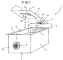
- an apparatus 1 comprises a leaktight, rigid casing, generally indicated 2.
- the casing 2 comprises a parallelepipedal tank-like container 3 having at the top an opening 4 provided with a peripheral flange 5 with which a closure lid 6 is coupled in a leaktight manner, for example, by means of screws indicated 7 in Figures 1 and 3.
- the leaktight container 2 houses various devices of the apparatus 1 which will be described further below. The specific description of the nature and arrangement of these devices will now be preceded by a short description of the circuit architecture of the apparatus 1, with reference to Figure 2.
- FIG 2 shows schematically a system for the supply of electrical energy on board a motor vehicle.
- the system comprises an energy generating and storage apparatus, generally indicated 10, including a generator 11 (an alternator) which can be driven by the internal combustion engine (not shown) of the motor vehicle, and a main storage battery 12 connected to the generator.
- the battery 12 is intended to be connected operatively to "normal", that is, non-priority electrical/electronic user devices which are generally represented in Figure 1 by a generic load indicated 13.
- the normal, that is, non-priority devices or loads comprise substantially all of the electrical loads on board with the exclusion of the electrical/electronic devices which form part of by-wire steering or braking systems or of other by-wire systems the functionality of which is essential for the safe handling of the motor vehicle.
- Two of these priority devices or loads are shown, indicated 14 and 15 in the diagram of Figure 2.
- the priority devices or loads are intended to be supplied operatively by means of the storage and supply apparatus 1 according to the invention.
- this apparatus comprises an auxiliary storage battery 20 to be connected operatively to the priority loads.
- the electrical-energy storage and supply apparatus 1 further comprises a controlled unidirectional DC/DC converter, generally indicated 21 in Figure 2.
- the converter is constituted by two sections 21a and 21b which are in parallel with one another in order to be able to ensure that a desired high output power value can be reached.
- the DC/DC converter 21 has its output connected to the positive terminal of the auxiliary battery 20 by means of a line 22 in which a normally open switch (a remote-control switch) indicated 23 in Figure 2 is interposed.
- a further normally open switch (remote-control switch) 24 is interposed between the input of the DC/DC converter 21 (in particular the input of the section 21a of that converter) and an input terminal 25 of the apparatus 1 which is operatively connected to the positive terminals of the battery 12 and of the generator 11.
- the switch 23 is controlled by a winding or solenoid 23a connected between the switch 24 and an earth conductor GND of the apparatus 1.
- the switch 24 is similarly controlled by a winding or solenoid 24a which in turn is driven by an electronic control unit 26 within the apparatus 1.
- the unit 26 has an input 26a which is connected to the terminal 25 of the apparatus 1 and an input 26b which is connected to the input terminal 27 of the apparatus 1 which in turn can be connected to the positive terminal of the battery 12 of the generator 11 by means of a switch 28.
- the latter can be closed manually, for example, by means of the key 29 for operating the ignition and starting switch of the motor vehicle.
- the unit 26 has a further terminal 26c which is connected to a terminal 30 of the apparatus 1.
- An indicator lamp 31 is connected between the terminal 30 of the apparatus 1 and the switch 28.
- the unit 26 is arranged to switch on the lamp 31 when it is necessary to indicate the occurrence of an operating anomaly or breakdown in the apparatus 1.
- the unit 26 has an input 26d which is connected to the terminal 37 of the apparatus 1 that is to be connected to an electronic control unit (not shown) of the vehicle in order to receive an operation enabling signal therefrom.
- the unit 26 also has an output 26e which is connected to terminals 32 and 33 of the apparatus 1 for connection to a communication network installed in the motor vehicle, for example, a network operating in accordance with the LIN protocol.
- the control unit 26 can input to the network through the output 26e malfunction diagnosis signals or signals of breakdowns which have occurred in the apparatus 1.
- a temperature sensor associated with the auxiliary battery 20 and connected to corresponding inputs of the control unit 26 is indicated 34 in Figure 2.
- the unit also has a plurality of terminals which are connected to the control inputs of the sections 21a and 21b of the DC/DC converter 21 as well as to the output of the converter.
- An electric motor for operating an electric fan 41 mounted in the casing 2 of the apparatus 1 in order to bring about recirculation of the air contained therein is indicated 35 in Figure 2.
- the motor 35 is connected between the remote-control switch 24 and the earth GND.
- the control unit 26 is arranged to drive the switches 23 and 24 in a manner such as to enable the DC/DC converter 21 to be connected to the generating apparatus 10 and to the auxiliary battery 20 of the apparatus 1 in predetermined operative conditions. This enablement is performed, for example, when the vehicle ignition and starting switch 28 is closed and in the presence of an enabling signal from the control system of the motor vehicle at the terminal 37 of the apparatus 1.
- the switch 23 automatically disconnects the output of the DC/DC converter 21 from the battery 20 when the switch 23 opens, preventing the battery 20 from being discharged into the output capacitor/s of the converter 21.
- the electronic control unit 26 is therefore arranged to estimate the charge state of the auxiliary battery 20 in accordance with predetermined procedures and to drive the DC/DC converter 21 in a manner such as to regulate the supply of electrical energy coming from the generating apparatus 10 (to the auxiliary battery 20) in a manner such that the estimated charge state of the battery 20 tends to be kept constantly at a predetermined reference value.
- the unit 26 modulates the power of the converter 21 in order to keep the charge state of the battery 20 at the desired value.
- This regulation or modulation may be continuous, that is, substantially proportional to the "error" between the reference value and the estimated charge state, or may be of the on/off type.
- the unit 26 is also advantageously arranged to emit, at the output 26e, diagnosis signals, for example, for the control system of the vehicle, to indicate the occurrence of fault events such as a permanent breakdown of one of the components of the apparatus 1 with consequent loss of the recharging function of the auxiliary battery 20, or a condition in which it is impossible to reach the target charge-state value of the battery 20, for example, because of transitory high-intensity phenomena or because of a lack of adequate voltage/power levels from the generating apparatus 10.
- diagnosis signals for example, for the control system of the vehicle, to indicate the occurrence of fault events such as a permanent breakdown of one of the components of the apparatus 1 with consequent loss of the recharging function of the auxiliary battery 20, or a condition in which it is impossible to reach the target charge-state value of the battery 20, for example, because of transitory high-intensity phenomena or because of a lack of adequate voltage/power levels from the generating apparatus 10.
- the apparatus 1 comprises a plurality of over-current protection devices, in particular, fuses 43 and 45, connected between the remote-control switch 24, the converter 21, and the unit 26 as well as between the remote-control switch 23 and the auxiliary battery 20 and between the positive terminal of the battery and the outputs for connection to the priority loads 14-15.
- over-current protection devices in particular, fuses 43 and 45
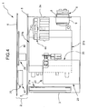
- the control unit 26 is carried by a card or board 40 fixed to the underside of the lid 6.
- the air-recirculation fan 41 the motor 35 of which has already been described above with reference to Figure 2, is fixed to the same side of the lid 6.
- the two sections 21a and 21b of the DC/DC converter 21 are fixed to two adjacent vertical side walls of the container 3 and the auxiliary battery 20 is located between the two sections, in particular in the vicinity of the section 21a.
- the fan 41 extends in the region between the adjacent sides of the two sections 21a and 21b of the DC/DC converter 21 and the auxiliary battery 20.
- the remote-control switch 24 is fixed to a support structure 42 ( Figure 3) arranged in the vicinity of the larger vertical wall of the container 3 facing that to which the section 21b of the converter 21 is fixed and in the vicinity of the front vertical wall 3a in which the multipole connector 9 is mounted.
- Some fuses 43 that is, the fuses relating to the positive terminal of the battery 20 and to the output of the control unit 26 (see also Figure 2) are mounted in the support structure 42.
- a further support structure 44 is also arranged in the container 3 of the apparatus 1 and houses further fuses, generally indicated 45, that is, the fuses relating to the remote switch 24 ( Figures 2 and 3) .
- the structure 44 is located in the upper portion of the tank-like container 3 in the vicinity of its front vertical wall 3a. In plan ( Figure 3), the structure 44 is located between the multipole connector 9 and the section 21b of the DC/DC converter 21.
- All of the electrical terminals of the above-described apparatus 1 are advantageously located in the multipole connector 9.
- the apparatus 1 as a whole can therefore be connected to the electrical-energy generating apparatus 10 and to other devices of the motor vehicle by a single wiring harness connected to the connector 9 and having branches or offtakes where necessary for local connection to individual devices.
- An apparatus is in fact an integrated energy storage and distribution system which can supply electrical energy to priority devices or loads reliably and safely.
- the apparatus provides a fault-tolerant electrical-energy distribution system for the priority loads, ensuring the supply of energy for a predetermined period of time defined at the design stage, even in the event of breakdown of the conventional generating and storage apparatus 10.
- Particularly advantageous aspects of the apparatus according to the invention are the integration of the protection devices, the electrical and mechanical layout which permits a compact construction, the facility to locate the apparatus even in regions of the vehicle which are exposed to atmospheric agents, and the modularity of the apparatus itself.
Priority Applications (4)
| Application Number | Priority Date | Filing Date | Title |
|---|---|---|---|
| AT05425734T ATE377846T1 (de) | 2005-10-19 | 2005-10-19 | Vorrichtung zum speichern von elektrischer energie für die versorgung von elektrischen lasten mit hoher priorität, insbesondere für motorfahrzeuge |
| EP05425734A EP1777772B1 (fr) | 2005-10-19 | 2005-10-19 | Dispositif pour le stockage de l'énergie électrique, pour l'alimentation des charges électriques de haute priorité, de préférence pour des véhicules motorisés |
| DE602005003237T DE602005003237T2 (de) | 2005-10-19 | 2005-10-19 | Vorrichtung zum Speichern von elektrischer Energie für die Versorgung von elektrischen Lasten mit hoher Priorität, insbesondere für Motorfahrzeuge |
| US11/420,888 US20070085418A1 (en) | 2005-10-19 | 2006-05-30 | Apparatus for the storage and supply of electrical energy for the supply of priority electrical loads, particularly for motor vehicles |
Applications Claiming Priority (1)
| Application Number | Priority Date | Filing Date | Title |
|---|---|---|---|
| EP05425734A EP1777772B1 (fr) | 2005-10-19 | 2005-10-19 | Dispositif pour le stockage de l'énergie électrique, pour l'alimentation des charges électriques de haute priorité, de préférence pour des véhicules motorisés |
Publications (2)
| Publication Number | Publication Date |
|---|---|
| EP1777772A1 true EP1777772A1 (fr) | 2007-04-25 |
| EP1777772B1 EP1777772B1 (fr) | 2007-11-07 |
Family
ID=35842362
Family Applications (1)
| Application Number | Title | Priority Date | Filing Date |
|---|---|---|---|
| EP05425734A Active EP1777772B1 (fr) | 2005-10-19 | 2005-10-19 | Dispositif pour le stockage de l'énergie électrique, pour l'alimentation des charges électriques de haute priorité, de préférence pour des véhicules motorisés |
Country Status (4)
| Country | Link |
|---|---|
| US (1) | US20070085418A1 (fr) |
| EP (1) | EP1777772B1 (fr) |
| AT (1) | ATE377846T1 (fr) |
| DE (1) | DE602005003237T2 (fr) |
Cited By (2)
| Publication number | Priority date | Publication date | Assignee | Title |
|---|---|---|---|---|
| US7509195B2 (en) * | 2003-01-17 | 2009-03-24 | General Motors Corporation | Driver control input device for drive-by-wire system |
| US8398412B2 (en) | 2009-03-16 | 2013-03-19 | Commissariat A L'energie Atomique Et Aux Energies Alternatives | Housing, electrical coupling including said housing, and vehicle including such a coupling |
Families Citing this family (5)
| Publication number | Priority date | Publication date | Assignee | Title |
|---|---|---|---|---|
| US9475459B2 (en) * | 2013-12-28 | 2016-10-25 | Tieman Vehicle Technologies LLC | Self-powered wireless fuse switch |
| US10211020B2 (en) | 2013-12-28 | 2019-02-19 | Blue Eclipse, Llc | Self-powered wireless fuse switch |
| JP6708100B2 (ja) * | 2016-11-17 | 2020-06-10 | 三菱自動車工業株式会社 | 車両 |
| JP6779820B2 (ja) * | 2017-03-24 | 2020-11-04 | 株式会社東芝 | 電極、二次電池、電池パック及び車両 |
| DE102021105053A1 (de) | 2021-03-03 | 2022-09-08 | Connaught Electronics Ltd. | Gehäuse für eine elektronische Recheneinrichtung eines Assistenzsystems eines Kraftfahrzeugs, Anordnung sowie Assistenzsystem |
Citations (3)
| Publication number | Priority date | Publication date | Assignee | Title |
|---|---|---|---|---|
| US5717310A (en) * | 1995-12-08 | 1998-02-10 | Honda Giken Kogyo Kabushiki Kaisha | Power supply control device for electric vehicle |
| US5739668A (en) * | 1995-12-05 | 1998-04-14 | Suzuki Motor Corporation | Charging control systems and circuits for recharging automobile batteries |
| US5783872A (en) * | 1996-07-25 | 1998-07-21 | Northrop Grumman Corporation | Auxiliary battery voltage/temperature compensation for automotive 12 volt system for electric vehicles |
Family Cites Families (7)
| Publication number | Priority date | Publication date | Assignee | Title |
|---|---|---|---|---|
| US3343060A (en) * | 1964-07-06 | 1967-09-19 | Introl Corp | Regulator circuit for battery chargers |
| US3681611A (en) * | 1971-05-26 | 1972-08-01 | Soltronics Inc | Vehicular remote power supply system |
| US5095260A (en) * | 1990-12-24 | 1992-03-10 | Century Manufacturing Company | Self limiting battery charger |
| US5697466A (en) * | 1992-11-12 | 1997-12-16 | Kabushikikaisha Equos Research | Hybrid vehicle |
| JP3347426B2 (ja) * | 1993-10-19 | 2002-11-20 | 本田技研工業株式会社 | 電動車両用充電器の冷却構造 |
| JP3611316B2 (ja) * | 2001-10-29 | 2005-01-19 | インターナショナル・ビジネス・マシーンズ・コーポレーション | 電気機器、コンピュータ装置、電源切換装置、および電源切換方法 |
| JP2005009474A (ja) * | 2003-05-26 | 2005-01-13 | Toyota Motor Corp | 動力出力装置およびその制御方法 |
-
2005
- 2005-10-19 AT AT05425734T patent/ATE377846T1/de not_active IP Right Cessation
- 2005-10-19 DE DE602005003237T patent/DE602005003237T2/de active Active
- 2005-10-19 EP EP05425734A patent/EP1777772B1/fr active Active
-
2006
- 2006-05-30 US US11/420,888 patent/US20070085418A1/en not_active Abandoned
Patent Citations (3)
| Publication number | Priority date | Publication date | Assignee | Title |
|---|---|---|---|---|
| US5739668A (en) * | 1995-12-05 | 1998-04-14 | Suzuki Motor Corporation | Charging control systems and circuits for recharging automobile batteries |
| US5717310A (en) * | 1995-12-08 | 1998-02-10 | Honda Giken Kogyo Kabushiki Kaisha | Power supply control device for electric vehicle |
| US5783872A (en) * | 1996-07-25 | 1998-07-21 | Northrop Grumman Corporation | Auxiliary battery voltage/temperature compensation for automotive 12 volt system for electric vehicles |
Cited By (2)
| Publication number | Priority date | Publication date | Assignee | Title |
|---|---|---|---|---|
| US7509195B2 (en) * | 2003-01-17 | 2009-03-24 | General Motors Corporation | Driver control input device for drive-by-wire system |
| US8398412B2 (en) | 2009-03-16 | 2013-03-19 | Commissariat A L'energie Atomique Et Aux Energies Alternatives | Housing, electrical coupling including said housing, and vehicle including such a coupling |
Also Published As
| Publication number | Publication date |
|---|---|
| DE602005003237D1 (de) | 2007-12-20 |
| ATE377846T1 (de) | 2007-11-15 |
| EP1777772B1 (fr) | 2007-11-07 |
| US20070085418A1 (en) | 2007-04-19 |
| DE602005003237T2 (de) | 2008-08-28 |
Similar Documents
| Publication | Publication Date | Title |
|---|---|---|
| EP1777772B1 (fr) | Dispositif pour le stockage de l'énergie électrique, pour l'alimentation des charges électriques de haute priorité, de préférence pour des véhicules motorisés | |
| CN110277596B (zh) | 电池和用于运行电池的方法 | |
| US7057306B2 (en) | Fuel cell and control unit in a detachable housing | |
| US5510658A (en) | Circuit breaker device for electric vehicle | |
| US8199449B2 (en) | Method and a device for monitoring high-voltage connections of a hybrid vehicle | |
| US9834102B2 (en) | In-vehicle power supply device | |
| JP3956814B2 (ja) | 高電圧機器収納箱 | |
| US20030155814A1 (en) | Device for power supply in a multi-voltage electric system of a motor vehicle | |
| US7109604B2 (en) | Device for distributing electrical energy and method for monitoring the distribution of energy | |
| CN110549890B (zh) | Dc/dc转换单元 | |
| US6476315B2 (en) | Solar system for a motor vehicle | |
| JP2011138685A (ja) | 蓄電装置 | |
| JPWO2010026715A1 (ja) | 車両用電源装置 | |
| JP2006327251A (ja) | 電源回路開閉装置 | |
| US6506061B2 (en) | Electrical connection box to be mounted on a vehicle | |
| EP2573909A1 (fr) | Système de gestion d'un véhicule | |
| JP2010093934A (ja) | 車載機器 | |
| CN110557017A (zh) | Dc/dc转换单元 | |
| JP2005304122A (ja) | ハイブリッド車用電池管理装置 | |
| US11390170B2 (en) | Power supply device having a fuel cell arrangement and method for lowering voltage in a fuel cell arrangement | |
| KR20210102435A (ko) | 전력 공급 네트워크 및 하이브리드 자동차 | |
| US20090174254A1 (en) | Pulse-width modulation rectifier having an emergency generator operating mode | |
| JP2015079585A (ja) | バッテリ監視装置、及び、バッテリ監視装置を備える電源装置 | |
| JP2020100259A (ja) | 車両用電源装置 | |
| KR101241798B1 (ko) | 하이브리드 자동차용 파워 릴레이 조립체 |
Legal Events
| Date | Code | Title | Description |
|---|---|---|---|
| PUAI | Public reference made under article 153(3) epc to a published international application that has entered the european phase |
Free format text: ORIGINAL CODE: 0009012 |
|
| 17P | Request for examination filed |
Effective date: 20060418 |
|
| AK | Designated contracting states |
Kind code of ref document: A1 Designated state(s): AT BE BG CH CY CZ DE DK EE ES FI FR GB GR HU IE IS IT LI LT LU LV MC NL PL PT RO SE SI SK TR |
|
| AX | Request for extension of the european patent |
Extension state: AL BA HR MK YU |
|
| GRAP | Despatch of communication of intention to grant a patent |
Free format text: ORIGINAL CODE: EPIDOSNIGR1 |
|
| RAP1 | Party data changed (applicant data changed or rights of an application transferred) |
Owner name: C.R.F. SOCIETA CONSORTILE PER AZIONI |
|
| GRAS | Grant fee paid |
Free format text: ORIGINAL CODE: EPIDOSNIGR3 |
|
| GRAA | (expected) grant |
Free format text: ORIGINAL CODE: 0009210 |
|
| AK | Designated contracting states |
Kind code of ref document: B1 Designated state(s): AT BE BG CH CY CZ DE DK EE ES FI FR GB GR HU IE IS IT LI LT LU LV MC NL PL PT RO SE SI SK TR |
|
| REG | Reference to a national code |
Ref country code: GB Ref legal event code: FG4D |
|
| REG | Reference to a national code |
Ref country code: IE Ref legal event code: FG4D |
|
| REG | Reference to a national code |
Ref country code: CH Ref legal event code: EP |
|
| REF | Corresponds to: |
Ref document number: 602005003237 Country of ref document: DE Date of ref document: 20071220 Kind code of ref document: P |
|
| AKX | Designation fees paid |
Designated state(s): AT BE BG CH CY CZ DE DK EE ES FI FR GB GR HU IE IS IT LI LT LU LV MC NL PL PT RO SE SI SK TR |
|
| PG25 | Lapsed in a contracting state [announced via postgrant information from national office to epo] |
Ref country code: NL Free format text: LAPSE BECAUSE OF FAILURE TO SUBMIT A TRANSLATION OF THE DESCRIPTION OR TO PAY THE FEE WITHIN THE PRESCRIBED TIME-LIMIT Effective date: 20071107 Ref country code: LI Free format text: LAPSE BECAUSE OF FAILURE TO SUBMIT A TRANSLATION OF THE DESCRIPTION OR TO PAY THE FEE WITHIN THE PRESCRIBED TIME-LIMIT Effective date: 20071107 Ref country code: CH Free format text: LAPSE BECAUSE OF FAILURE TO SUBMIT A TRANSLATION OF THE DESCRIPTION OR TO PAY THE FEE WITHIN THE PRESCRIBED TIME-LIMIT Effective date: 20071107 Ref country code: SE Free format text: LAPSE BECAUSE OF FAILURE TO SUBMIT A TRANSLATION OF THE DESCRIPTION OR TO PAY THE FEE WITHIN THE PRESCRIBED TIME-LIMIT Effective date: 20080207 Ref country code: ES Free format text: LAPSE BECAUSE OF FAILURE TO SUBMIT A TRANSLATION OF THE DESCRIPTION OR TO PAY THE FEE WITHIN THE PRESCRIBED TIME-LIMIT Effective date: 20080218 |
|
| NLV1 | Nl: lapsed or annulled due to failure to fulfill the requirements of art. 29p and 29m of the patents act | ||
| PG25 | Lapsed in a contracting state [announced via postgrant information from national office to epo] |
Ref country code: SI Free format text: LAPSE BECAUSE OF FAILURE TO SUBMIT A TRANSLATION OF THE DESCRIPTION OR TO PAY THE FEE WITHIN THE PRESCRIBED TIME-LIMIT Effective date: 20071107 Ref country code: LV Free format text: LAPSE BECAUSE OF FAILURE TO SUBMIT A TRANSLATION OF THE DESCRIPTION OR TO PAY THE FEE WITHIN THE PRESCRIBED TIME-LIMIT Effective date: 20071107 Ref country code: LT Free format text: LAPSE BECAUSE OF FAILURE TO SUBMIT A TRANSLATION OF THE DESCRIPTION OR TO PAY THE FEE WITHIN THE PRESCRIBED TIME-LIMIT Effective date: 20071107 Ref country code: PL Free format text: LAPSE BECAUSE OF FAILURE TO SUBMIT A TRANSLATION OF THE DESCRIPTION OR TO PAY THE FEE WITHIN THE PRESCRIBED TIME-LIMIT Effective date: 20071107 Ref country code: IS Free format text: LAPSE BECAUSE OF FAILURE TO SUBMIT A TRANSLATION OF THE DESCRIPTION OR TO PAY THE FEE WITHIN THE PRESCRIBED TIME-LIMIT Effective date: 20080307 Ref country code: BG Free format text: LAPSE BECAUSE OF FAILURE TO SUBMIT A TRANSLATION OF THE DESCRIPTION OR TO PAY THE FEE WITHIN THE PRESCRIBED TIME-LIMIT Effective date: 20080207 |
|
| REG | Reference to a national code |
Ref country code: CH Ref legal event code: PL |
|
| ET | Fr: translation filed | ||
| PG25 | Lapsed in a contracting state [announced via postgrant information from national office to epo] |
Ref country code: AT Free format text: LAPSE BECAUSE OF FAILURE TO SUBMIT A TRANSLATION OF THE DESCRIPTION OR TO PAY THE FEE WITHIN THE PRESCRIBED TIME-LIMIT Effective date: 20071107 |
|
| PG25 | Lapsed in a contracting state [announced via postgrant information from national office to epo] |
Ref country code: DK Free format text: LAPSE BECAUSE OF FAILURE TO SUBMIT A TRANSLATION OF THE DESCRIPTION OR TO PAY THE FEE WITHIN THE PRESCRIBED TIME-LIMIT Effective date: 20071107 Ref country code: CZ Free format text: LAPSE BECAUSE OF FAILURE TO SUBMIT A TRANSLATION OF THE DESCRIPTION OR TO PAY THE FEE WITHIN THE PRESCRIBED TIME-LIMIT Effective date: 20071107 |
|
| PG25 | Lapsed in a contracting state [announced via postgrant information from national office to epo] |
Ref country code: RO Free format text: LAPSE BECAUSE OF FAILURE TO SUBMIT A TRANSLATION OF THE DESCRIPTION OR TO PAY THE FEE WITHIN THE PRESCRIBED TIME-LIMIT Effective date: 20071107 Ref country code: SK Free format text: LAPSE BECAUSE OF FAILURE TO SUBMIT A TRANSLATION OF THE DESCRIPTION OR TO PAY THE FEE WITHIN THE PRESCRIBED TIME-LIMIT Effective date: 20071107 Ref country code: BE Free format text: LAPSE BECAUSE OF FAILURE TO SUBMIT A TRANSLATION OF THE DESCRIPTION OR TO PAY THE FEE WITHIN THE PRESCRIBED TIME-LIMIT Effective date: 20071107 |
|
| PLBE | No opposition filed within time limit |
Free format text: ORIGINAL CODE: 0009261 |
|
| STAA | Information on the status of an ep patent application or granted ep patent |
Free format text: STATUS: NO OPPOSITION FILED WITHIN TIME LIMIT |
|
| PG25 | Lapsed in a contracting state [announced via postgrant information from national office to epo] |
Ref country code: PT Free format text: LAPSE BECAUSE OF FAILURE TO SUBMIT A TRANSLATION OF THE DESCRIPTION OR TO PAY THE FEE WITHIN THE PRESCRIBED TIME-LIMIT Effective date: 20080407 |
|
| 26N | No opposition filed |
Effective date: 20080808 |
|
| PG25 | Lapsed in a contracting state [announced via postgrant information from national office to epo] |
Ref country code: GR Free format text: LAPSE BECAUSE OF FAILURE TO SUBMIT A TRANSLATION OF THE DESCRIPTION OR TO PAY THE FEE WITHIN THE PRESCRIBED TIME-LIMIT Effective date: 20080208 |
|
| PG25 | Lapsed in a contracting state [announced via postgrant information from national office to epo] |
Ref country code: FI Free format text: LAPSE BECAUSE OF FAILURE TO SUBMIT A TRANSLATION OF THE DESCRIPTION OR TO PAY THE FEE WITHIN THE PRESCRIBED TIME-LIMIT Effective date: 20071107 |
|
| PG25 | Lapsed in a contracting state [announced via postgrant information from national office to epo] |
Ref country code: EE Free format text: LAPSE BECAUSE OF FAILURE TO SUBMIT A TRANSLATION OF THE DESCRIPTION OR TO PAY THE FEE WITHIN THE PRESCRIBED TIME-LIMIT Effective date: 20071107 |
|
| PG25 | Lapsed in a contracting state [announced via postgrant information from national office to epo] |
Ref country code: MC Free format text: LAPSE BECAUSE OF NON-PAYMENT OF DUE FEES Effective date: 20081031 |
|
| PG25 | Lapsed in a contracting state [announced via postgrant information from national office to epo] |
Ref country code: CY Free format text: LAPSE BECAUSE OF FAILURE TO SUBMIT A TRANSLATION OF THE DESCRIPTION OR TO PAY THE FEE WITHIN THE PRESCRIBED TIME-LIMIT Effective date: 20071107 |
|
| PG25 | Lapsed in a contracting state [announced via postgrant information from national office to epo] |
Ref country code: IE Free format text: LAPSE BECAUSE OF NON-PAYMENT OF DUE FEES Effective date: 20081020 |
|
| PG25 | Lapsed in a contracting state [announced via postgrant information from national office to epo] |
Ref country code: LU Free format text: LAPSE BECAUSE OF NON-PAYMENT OF DUE FEES Effective date: 20081019 Ref country code: HU Free format text: LAPSE BECAUSE OF FAILURE TO SUBMIT A TRANSLATION OF THE DESCRIPTION OR TO PAY THE FEE WITHIN THE PRESCRIBED TIME-LIMIT Effective date: 20080508 |
|
| PG25 | Lapsed in a contracting state [announced via postgrant information from national office to epo] |
Ref country code: TR Free format text: LAPSE BECAUSE OF FAILURE TO SUBMIT A TRANSLATION OF THE DESCRIPTION OR TO PAY THE FEE WITHIN THE PRESCRIBED TIME-LIMIT Effective date: 20071107 |
|
| PG25 | Lapsed in a contracting state [announced via postgrant information from national office to epo] |
Ref country code: GB Free format text: LAPSE BECAUSE OF NON-PAYMENT OF DUE FEES Effective date: 20091019 |
|
| REG | Reference to a national code |
Ref country code: FR Ref legal event code: PLFP Year of fee payment: 11 |
|
| REG | Reference to a national code |
Ref country code: FR Ref legal event code: PLFP Year of fee payment: 12 |
|
| REG | Reference to a national code |
Ref country code: FR Ref legal event code: PLFP Year of fee payment: 13 |
|
| REG | Reference to a national code |
Ref country code: FR Ref legal event code: PLFP Year of fee payment: 14 |
|
| PGFP | Annual fee paid to national office [announced via postgrant information from national office to epo] |
Ref country code: FR Payment date: 20220920 Year of fee payment: 18 |
|
| PGFP | Annual fee paid to national office [announced via postgrant information from national office to epo] |
Ref country code: IT Payment date: 20220908 Year of fee payment: 18 Ref country code: DE Payment date: 20220920 Year of fee payment: 18 |