EP1777715A1 - Electric double layer capacitor - Google Patents
Electric double layer capacitor Download PDFInfo
- Publication number
- EP1777715A1 EP1777715A1 EP06017805A EP06017805A EP1777715A1 EP 1777715 A1 EP1777715 A1 EP 1777715A1 EP 06017805 A EP06017805 A EP 06017805A EP 06017805 A EP06017805 A EP 06017805A EP 1777715 A1 EP1777715 A1 EP 1777715A1
- Authority
- EP
- European Patent Office
- Prior art keywords
- external
- circumferential wall
- lid
- double layer
- electric double
- Prior art date
- Legal status (The legal status is an assumption and is not a legal conclusion. Google has not performed a legal analysis and makes no representation as to the accuracy of the status listed.)
- Withdrawn
Links
- 239000003990 capacitor Substances 0.000 title claims abstract description 46
- 239000008151 electrolyte solution Substances 0.000 claims description 11
- 230000002093 peripheral effect Effects 0.000 claims description 10
- 239000004696 Poly ether ether ketone Substances 0.000 claims description 3
- 229920002530 polyetherether ketone Polymers 0.000 claims description 3
- 238000002844 melting Methods 0.000 claims description 2
- 230000008018 melting Effects 0.000 claims description 2
- 229910000679 solder Inorganic materials 0.000 claims description 2
- OKTJSMMVPCPJKN-UHFFFAOYSA-N Carbon Chemical compound [C] OKTJSMMVPCPJKN-UHFFFAOYSA-N 0.000 description 22
- -1 triethylmethylammonium tetrafluoroborate Chemical compound 0.000 description 15
- 239000000463 material Substances 0.000 description 8
- 238000000034 method Methods 0.000 description 7
- 238000005452 bending Methods 0.000 description 6
- 230000000052 comparative effect Effects 0.000 description 6
- 239000000835 fiber Substances 0.000 description 5
- RUOJZAUFBMNUDX-UHFFFAOYSA-N propylene carbonate Chemical compound CC1COC(=O)O1 RUOJZAUFBMNUDX-UHFFFAOYSA-N 0.000 description 5
- WNXJIVFYUVYPPR-UHFFFAOYSA-N 1,3-dioxolane Chemical compound C1COCO1 WNXJIVFYUVYPPR-UHFFFAOYSA-N 0.000 description 4
- RTZKZFJDLAIYFH-UHFFFAOYSA-N Diethyl ether Chemical compound CCOCC RTZKZFJDLAIYFH-UHFFFAOYSA-N 0.000 description 4
- WYURNTSHIVDZCO-UHFFFAOYSA-N Tetrahydrofuran Chemical compound C1CCOC1 WYURNTSHIVDZCO-UHFFFAOYSA-N 0.000 description 4
- 239000011248 coating agent Substances 0.000 description 4
- 238000000576 coating method Methods 0.000 description 4
- 150000003839 salts Chemical class 0.000 description 4
- 239000002904 solvent Substances 0.000 description 4
- HXJUTPCZVOIRIF-UHFFFAOYSA-N sulfolane Chemical compound O=S1(=O)CCCC1 HXJUTPCZVOIRIF-UHFFFAOYSA-N 0.000 description 4
- WEVYAHXRMPXWCK-UHFFFAOYSA-N Acetonitrile Chemical compound CC#N WEVYAHXRMPXWCK-UHFFFAOYSA-N 0.000 description 3
- ZMXDDKWLCZADIW-UHFFFAOYSA-N N,N-Dimethylformamide Chemical compound CN(C)C=O ZMXDDKWLCZADIW-UHFFFAOYSA-N 0.000 description 3
- 239000011149 active material Substances 0.000 description 3
- 239000011230 binding agent Substances 0.000 description 3
- 239000003795 chemical substances by application Substances 0.000 description 3
- 239000006258 conductive agent Substances 0.000 description 3
- 238000002788 crimping Methods 0.000 description 3
- 239000000203 mixture Substances 0.000 description 3
- YEJRWHAVMIAJKC-UHFFFAOYSA-N 4-Butyrolactone Chemical compound O=C1CCCO1 YEJRWHAVMIAJKC-UHFFFAOYSA-N 0.000 description 2
- QTBSBXVTEAMEQO-UHFFFAOYSA-N Acetic acid Natural products CC(O)=O QTBSBXVTEAMEQO-UHFFFAOYSA-N 0.000 description 2
- XTHFKEDIFFGKHM-UHFFFAOYSA-N Dimethoxyethane Chemical compound COCCOC XTHFKEDIFFGKHM-UHFFFAOYSA-N 0.000 description 2
- IAZDPXIOMUYVGZ-UHFFFAOYSA-N Dimethylsulphoxide Chemical compound CS(C)=O IAZDPXIOMUYVGZ-UHFFFAOYSA-N 0.000 description 2
- ZHNUHDYFZUAESO-UHFFFAOYSA-N Formamide Chemical compound NC=O ZHNUHDYFZUAESO-UHFFFAOYSA-N 0.000 description 2
- OFOBLEOULBTSOW-UHFFFAOYSA-N Malonic acid Chemical compound OC(=O)CC(O)=O OFOBLEOULBTSOW-UHFFFAOYSA-N 0.000 description 2
- 239000006230 acetylene black Substances 0.000 description 2
- 238000001994 activation Methods 0.000 description 2
- MTHSVFCYNBDYFN-UHFFFAOYSA-N anhydrous diethylene glycol Natural products OCCOCCO MTHSVFCYNBDYFN-UHFFFAOYSA-N 0.000 description 2
- 239000011530 conductive current collector Substances 0.000 description 2
- XBDQKXXYIPTUBI-UHFFFAOYSA-N dimethylselenoniopropionate Natural products CCC(O)=O XBDQKXXYIPTUBI-UHFFFAOYSA-N 0.000 description 2
- 230000000694 effects Effects 0.000 description 2
- 150000002148 esters Chemical class 0.000 description 2
- FKRCODPIKNYEAC-UHFFFAOYSA-N ethyl propionate Chemical compound CCOC(=O)CC FKRCODPIKNYEAC-UHFFFAOYSA-N 0.000 description 2
- LYCAIKOWRPUZTN-UHFFFAOYSA-N ethylene glycol Natural products OCCO LYCAIKOWRPUZTN-UHFFFAOYSA-N 0.000 description 2
- GAEKPEKOJKCEMS-UHFFFAOYSA-N gamma-valerolactone Chemical compound CC1CCC(=O)O1 GAEKPEKOJKCEMS-UHFFFAOYSA-N 0.000 description 2
- 229910002804 graphite Inorganic materials 0.000 description 2
- 239000010439 graphite Substances 0.000 description 2
- TZIHFWKZFHZASV-UHFFFAOYSA-N methyl formate Chemical compound COC=O TZIHFWKZFHZASV-UHFFFAOYSA-N 0.000 description 2
- 238000012986 modification Methods 0.000 description 2
- 230000004048 modification Effects 0.000 description 2
- 239000003960 organic solvent Substances 0.000 description 2
- 239000004810 polytetrafluoroethylene Substances 0.000 description 2
- 229920001343 polytetrafluoroethylene Polymers 0.000 description 2
- 239000011148 porous material Substances 0.000 description 2
- 238000002360 preparation method Methods 0.000 description 2
- YLQBMQCUIZJEEH-UHFFFAOYSA-N tetrahydrofuran Natural products C=1C=COC=1 YLQBMQCUIZJEEH-UHFFFAOYSA-N 0.000 description 2
- ZZXUZKXVROWEIF-UHFFFAOYSA-N 1,2-butylene carbonate Chemical compound CCC1COC(=O)O1 ZZXUZKXVROWEIF-UHFFFAOYSA-N 0.000 description 1
- RRQYJINTUHWNHW-UHFFFAOYSA-N 1-ethoxy-2-(2-ethoxyethoxy)ethane Chemical compound CCOCCOCCOCC RRQYJINTUHWNHW-UHFFFAOYSA-N 0.000 description 1
- KIAMPLQEZAMORJ-UHFFFAOYSA-N 1-ethoxy-2-[2-(2-ethoxyethoxy)ethoxy]ethane Chemical compound CCOCCOCCOCCOCC KIAMPLQEZAMORJ-UHFFFAOYSA-N 0.000 description 1
- JWUJQDFVADABEY-UHFFFAOYSA-N 2-methyltetrahydrofuran Chemical compound CC1CCCO1 JWUJQDFVADABEY-UHFFFAOYSA-N 0.000 description 1
- OMQHDIHZSDEIFH-UHFFFAOYSA-N 3-Acetyldihydro-2(3H)-furanone Chemical compound CC(=O)C1CCOC1=O OMQHDIHZSDEIFH-UHFFFAOYSA-N 0.000 description 1
- CMJLMPKFQPJDKP-UHFFFAOYSA-N 3-methylthiolane 1,1-dioxide Chemical compound CC1CCS(=O)(=O)C1 CMJLMPKFQPJDKP-UHFFFAOYSA-N 0.000 description 1
- 229920000049 Carbon (fiber) Polymers 0.000 description 1
- 239000004215 Carbon black (E152) Substances 0.000 description 1
- 229920002134 Carboxymethyl cellulose Polymers 0.000 description 1
- 235000013162 Cocos nucifera Nutrition 0.000 description 1
- 244000060011 Cocos nucifera Species 0.000 description 1
- OIFBSDVPJOWBCH-UHFFFAOYSA-N Diethyl carbonate Chemical compound CCOC(=O)OCC OIFBSDVPJOWBCH-UHFFFAOYSA-N 0.000 description 1
- QGLBZNZGBLRJGS-UHFFFAOYSA-N Dihydro-3-methyl-2(3H)-furanone Chemical compound CC1CCOC1=O QGLBZNZGBLRJGS-UHFFFAOYSA-N 0.000 description 1
- 229920002943 EPDM rubber Polymers 0.000 description 1
- KMTRUDSVKNLOMY-UHFFFAOYSA-N Ethylene carbonate Chemical compound O=C1OCCO1 KMTRUDSVKNLOMY-UHFFFAOYSA-N 0.000 description 1
- YCKRFDGAMUMZLT-UHFFFAOYSA-N Fluorine atom Chemical compound [F] YCKRFDGAMUMZLT-UHFFFAOYSA-N 0.000 description 1
- 229910001290 LiPF6 Inorganic materials 0.000 description 1
- RJUFJBKOKNCXHH-UHFFFAOYSA-N Methyl propionate Chemical compound CCC(=O)OC RJUFJBKOKNCXHH-UHFFFAOYSA-N 0.000 description 1
- 229910019142 PO4 Inorganic materials 0.000 description 1
- 239000002033 PVDF binder Substances 0.000 description 1
- ISWSIDIOOBJBQZ-UHFFFAOYSA-N Phenol Chemical compound OC1=CC=CC=C1 ISWSIDIOOBJBQZ-UHFFFAOYSA-N 0.000 description 1
- 239000004962 Polyamide-imide Substances 0.000 description 1
- 239000004698 Polyethylene Substances 0.000 description 1
- 239000004642 Polyimide Substances 0.000 description 1
- 239000004734 Polyphenylene sulfide Substances 0.000 description 1
- 239000004743 Polypropylene Substances 0.000 description 1
- XBDQKXXYIPTUBI-UHFFFAOYSA-M Propionate Chemical compound CCC([O-])=O XBDQKXXYIPTUBI-UHFFFAOYSA-M 0.000 description 1
- 229920000297 Rayon Polymers 0.000 description 1
- KXKVLQRXCPHEJC-UHFFFAOYSA-N acetic acid trimethyl ester Natural products COC(C)=O KXKVLQRXCPHEJC-UHFFFAOYSA-N 0.000 description 1
- 229910021383 artificial graphite Inorganic materials 0.000 description 1
- 239000010426 asphalt Substances 0.000 description 1
- FWBMVXOCTXTBAD-UHFFFAOYSA-N butyl methyl carbonate Chemical compound CCCCOC(=O)OC FWBMVXOCTXTBAD-UHFFFAOYSA-N 0.000 description 1
- VASVAWIFVXAQMI-UHFFFAOYSA-N butyl propyl carbonate Chemical compound CCCCOC(=O)OCCC VASVAWIFVXAQMI-UHFFFAOYSA-N 0.000 description 1
- 229920005549 butyl rubber Polymers 0.000 description 1
- 239000004917 carbon fiber Substances 0.000 description 1
- 239000002041 carbon nanotube Substances 0.000 description 1
- 229910021393 carbon nanotube Inorganic materials 0.000 description 1
- 239000003575 carbonaceous material Substances 0.000 description 1
- 238000003763 carbonization Methods 0.000 description 1
- 239000001768 carboxy methyl cellulose Substances 0.000 description 1
- 235000010948 carboxy methyl cellulose Nutrition 0.000 description 1
- 239000008112 carboxymethyl-cellulose Substances 0.000 description 1
- 150000001875 compounds Chemical class 0.000 description 1
- 238000002425 crystallisation Methods 0.000 description 1
- 230000008025 crystallization Effects 0.000 description 1
- 150000004292 cyclic ethers Chemical class 0.000 description 1
- 125000004122 cyclic group Chemical group 0.000 description 1
- 229960004132 diethyl ether Drugs 0.000 description 1
- 229940019778 diethylene glycol diethyl ether Drugs 0.000 description 1
- IEJIGPNLZYLLBP-UHFFFAOYSA-N dimethyl carbonate Chemical compound COC(=O)OC IEJIGPNLZYLLBP-UHFFFAOYSA-N 0.000 description 1
- VUPKGFBOKBGHFZ-UHFFFAOYSA-N dipropyl carbonate Chemical compound CCCOC(=O)OCCC VUPKGFBOKBGHFZ-UHFFFAOYSA-N 0.000 description 1
- 229920001971 elastomer Polymers 0.000 description 1
- 230000002708 enhancing effect Effects 0.000 description 1
- 239000003822 epoxy resin Substances 0.000 description 1
- 150000002170 ethers Chemical class 0.000 description 1
- 229940052303 ethers for general anesthesia Drugs 0.000 description 1
- JBTWLSYIZRCDFO-UHFFFAOYSA-N ethyl methyl carbonate Chemical compound CCOC(=O)OC JBTWLSYIZRCDFO-UHFFFAOYSA-N 0.000 description 1
- QKBJDEGZZJWPJA-UHFFFAOYSA-N ethyl propyl carbonate Chemical compound [CH2]COC(=O)OCCC QKBJDEGZZJWPJA-UHFFFAOYSA-N 0.000 description 1
- 238000002474 experimental method Methods 0.000 description 1
- 239000002657 fibrous material Substances 0.000 description 1
- 229910052731 fluorine Inorganic materials 0.000 description 1
- 239000011737 fluorine Substances 0.000 description 1
- NBVXSUQYWXRMNV-UHFFFAOYSA-N fluoromethane Chemical compound FC NBVXSUQYWXRMNV-UHFFFAOYSA-N 0.000 description 1
- 239000003365 glass fiber Substances 0.000 description 1
- 238000010438 heat treatment Methods 0.000 description 1
- 229930195733 hydrocarbon Natural products 0.000 description 1
- 150000002430 hydrocarbons Chemical class 0.000 description 1
- 229920002681 hypalon Polymers 0.000 description 1
- 230000010220 ion permeability Effects 0.000 description 1
- 239000003273 ketjen black Substances 0.000 description 1
- 239000007788 liquid Substances 0.000 description 1
- MHCFAGZWMAWTNR-UHFFFAOYSA-M lithium perchlorate Chemical compound [Li+].[O-]Cl(=O)(=O)=O MHCFAGZWMAWTNR-UHFFFAOYSA-M 0.000 description 1
- 229910001486 lithium perchlorate Inorganic materials 0.000 description 1
- 229910001496 lithium tetrafluoroborate Inorganic materials 0.000 description 1
- QSZMZKBZAYQGRS-UHFFFAOYSA-N lithium;bis(trifluoromethylsulfonyl)azanide Chemical compound [Li+].FC(F)(F)S(=O)(=O)[N-]S(=O)(=O)C(F)(F)F QSZMZKBZAYQGRS-UHFFFAOYSA-N 0.000 description 1
- FPYJFEHAWHCUMM-UHFFFAOYSA-N maleic anhydride Chemical compound O=C1OC(=O)C=C1 FPYJFEHAWHCUMM-UHFFFAOYSA-N 0.000 description 1
- VNWKTOKETHGBQD-UHFFFAOYSA-N methane Chemical class C VNWKTOKETHGBQD-UHFFFAOYSA-N 0.000 description 1
- 229940017219 methyl propionate Drugs 0.000 description 1
- 239000012046 mixed solvent Substances 0.000 description 1
- 229910021382 natural graphite Inorganic materials 0.000 description 1
- LYGJENNIWJXYER-UHFFFAOYSA-N nitromethane Chemical compound C[N+]([O-])=O LYGJENNIWJXYER-UHFFFAOYSA-N 0.000 description 1
- NBIIXXVUZAFLBC-UHFFFAOYSA-K phosphate Chemical compound [O-]P([O-])([O-])=O NBIIXXVUZAFLBC-UHFFFAOYSA-K 0.000 description 1
- 239000010452 phosphate Substances 0.000 description 1
- 229920002312 polyamide-imide Polymers 0.000 description 1
- 229920000647 polyepoxide Polymers 0.000 description 1
- 229920000573 polyethylene Polymers 0.000 description 1
- 229920001223 polyethylene glycol Polymers 0.000 description 1
- 229920000139 polyethylene terephthalate Polymers 0.000 description 1
- 239000005020 polyethylene terephthalate Substances 0.000 description 1
- 229920001721 polyimide Polymers 0.000 description 1
- 229920000069 polyphenylene sulfide Polymers 0.000 description 1
- 229920001155 polypropylene Polymers 0.000 description 1
- 229920000915 polyvinyl chloride Polymers 0.000 description 1
- 239000004800 polyvinyl chloride Substances 0.000 description 1
- 229920002981 polyvinylidene fluoride Polymers 0.000 description 1
- 229920000036 polyvinylpyrrolidone Polymers 0.000 description 1
- 239000001267 polyvinylpyrrolidone Substances 0.000 description 1
- 235000013855 polyvinylpyrrolidone Nutrition 0.000 description 1
- 235000019353 potassium silicate Nutrition 0.000 description 1
- 235000019260 propionic acid Nutrition 0.000 description 1
- 239000002964 rayon Substances 0.000 description 1
- 229920005989 resin Polymers 0.000 description 1
- 239000011347 resin Substances 0.000 description 1
- 239000011369 resultant mixture Substances 0.000 description 1
- 239000005060 rubber Substances 0.000 description 1
- 239000000565 sealant Substances 0.000 description 1
- 238000007789 sealing Methods 0.000 description 1
- NTHWMYGWWRZVTN-UHFFFAOYSA-N sodium silicate Chemical compound [Na+].[Na+].[O-][Si]([O-])=O NTHWMYGWWRZVTN-UHFFFAOYSA-N 0.000 description 1
- 238000005476 soldering Methods 0.000 description 1
- 229910001220 stainless steel Inorganic materials 0.000 description 1
- 239000010935 stainless steel Substances 0.000 description 1
- 229920003048 styrene butadiene rubber Polymers 0.000 description 1
Images


Classifications
-
- H—ELECTRICITY
- H01—ELECTRIC ELEMENTS
- H01G—CAPACITORS; CAPACITORS, RECTIFIERS, DETECTORS, SWITCHING DEVICES, LIGHT-SENSITIVE OR TEMPERATURE-SENSITIVE DEVICES OF THE ELECTROLYTIC TYPE
- H01G11/00—Hybrid capacitors, i.e. capacitors having different positive and negative electrodes; Electric double-layer [EDL] capacitors; Processes for the manufacture thereof or of parts thereof
- H01G11/78—Cases; Housings; Encapsulations; Mountings
- H01G11/80—Gaskets; Sealings
-
- H—ELECTRICITY
- H01—ELECTRIC ELEMENTS
- H01G—CAPACITORS; CAPACITORS, RECTIFIERS, DETECTORS, SWITCHING DEVICES, LIGHT-SENSITIVE OR TEMPERATURE-SENSITIVE DEVICES OF THE ELECTROLYTIC TYPE
- H01G11/00—Hybrid capacitors, i.e. capacitors having different positive and negative electrodes; Electric double-layer [EDL] capacitors; Processes for the manufacture thereof or of parts thereof
- H01G11/78—Cases; Housings; Encapsulations; Mountings
- H01G11/82—Fixing or assembling a capacitive element in a housing, e.g. mounting electrodes, current collectors or terminals in containers or encapsulations
-
- H—ELECTRICITY
- H01—ELECTRIC ELEMENTS
- H01G—CAPACITORS; CAPACITORS, RECTIFIERS, DETECTORS, SWITCHING DEVICES, LIGHT-SENSITIVE OR TEMPERATURE-SENSITIVE DEVICES OF THE ELECTROLYTIC TYPE
- H01G9/00—Electrolytic capacitors, rectifiers, detectors, switching devices, light-sensitive or temperature-sensitive devices; Processes of their manufacture
- H01G9/004—Details
- H01G9/08—Housing; Encapsulation
- H01G9/10—Sealing, e.g. of lead-in wires
-
- Y—GENERAL TAGGING OF NEW TECHNOLOGICAL DEVELOPMENTS; GENERAL TAGGING OF CROSS-SECTIONAL TECHNOLOGIES SPANNING OVER SEVERAL SECTIONS OF THE IPC; TECHNICAL SUBJECTS COVERED BY FORMER USPC CROSS-REFERENCE ART COLLECTIONS [XRACs] AND DIGESTS
- Y02—TECHNOLOGIES OR APPLICATIONS FOR MITIGATION OR ADAPTATION AGAINST CLIMATE CHANGE
- Y02E—REDUCTION OF GREENHOUSE GAS [GHG] EMISSIONS, RELATED TO ENERGY GENERATION, TRANSMISSION OR DISTRIBUTION
- Y02E60/00—Enabling technologies; Technologies with a potential or indirect contribution to GHG emissions mitigation
- Y02E60/13—Energy storage using capacitors
Definitions
- the present invention relates to a button-shaped electric double layer capacitor comprising a pair of electrodes opposing each other with a separator interposed therebetween in which an electrolyte solution is impregnated.
- a button-shaped electric double layer capacitor as shown in Fig. 4 is well known.
- the electric double layer capacitor has an electrode unit 110 in which a first polarizable electrode 101 made of, for example, activated carbon, and a second polarizable electrode 102 also made of, for example, activated carbon, are opposed to each other across a separator 103 interposed between the electrodes.
- the electrode unit 110 is impregnated with an electrolyte solution.
- the first polarizable electrode 101 is electrically connected via a first current collector 106 to an external lid 104, which serves as the cathode terminal
- the second polarizable electrode 102 is electrically connected via a second current collector 107 to an external case 105, which serves as the anode terminal.
- the electrode unit 110 is accommodated in an accommodating space defined by the external case 105 and the external lid 104.
- the external lid 104 has a shallow dish-like shape. Specifically, it comprises a top wall 104a, a first circumferential wall 104b having a smaller diameter and adjoining the peripheral edge of the top wall 104a, and a second circumferential wall 104c having a larger diameter and adjoining the first circumferential wall 104b.
- the external case 105 has a shallow dish-like shape, and specifically, it comprises a bottom wall 105a and a circumferential wall 105b adjoining the peripheral edge of the bottom wall 105a.
- An electrically insulative gasket 108 is disposed between the inner surface of the circumferential wall 105b and the outer surfaces of the first circumferential wall 104b and the second circumferential wall 104c.
- An open end part 105c of the external case 105 is bent inwardly, whereby the accommodating space defined by the external case 105 and the external lid 104 is hermetically closed.
- a folded part 104d is formed at the edge part of the second circumferential wall 104c. The folded part 104d serves to improve the strength of the external lid 104, and to apply pressure to the gasket 108 so that the hermeticity can be improved. (See, for example, page 2 and Fig. 3 of Japanese Published Unexamined Patent Application No. 8-222192 ).
- the presence of the folded part 104d narrows the accommodating space, which is formed by the external lid 104 and the external case 105. Specifically, the diameter of the first circumferential wall 104b of the external lid 104 needs to be made smaller corresponding to the thickness increase of the external lid, which is due to the provision of the folded part 104d. Therefore, the diameter of the electrode unit 110 placed in the accommodating space cannot be made large, so the capacitance of the electric double layer capacitor cannot be increased if the size of the electric double layer capacitor is fixed.
- an electric double layer capacitor comprising: a) an electrode unit having a separator, first and second electrodes opposing each other across the separator therebetween, and an electrolyte solution impregnated in the electrode unit; b) an external lid, formed in a flattened U-shape in cross section, having a top wall and a circumferential wall adjoining the peripheral edge of the top wall; c) an external case, formed in a flattened U-shape in cross section, having a bottom wall and a circumferential wall adjoining the peripheral edge of the bottom wall; and d) a gasket disposed between an outer surface of the external lid and an inner surface of the external case, the electric double layer capacitor being configured so that the external case has an open end part that is bent inwardly with the external lid and the external case being disposed so that inner surfaces of the top wall and the bottom wall face each other, to hermetically close an accommodating space, formed by the external case and the external lid, for
- the configuration in which the thickness of at least the circumferential wall of the external lid is greater than the thickness of the external case as described above allows the strength of the external lid to be greater, and therefore, can prevent deformation of the external lid such as crimping even when a large pressure acts on the external lid in the process step of hermetically closing the accommodating space formed by the external case and the external lid by bending the open end part of the external case inwardly. As a result, hermeticity of the external case and the external lid can be improved.
- the configuration in which the circumferential wall of the external lid extends substantially linearly toward the bottom wall of the external case allows the space in which both electrodes are disposed to be greater than that of the conventional products, making it possible to increase the capacitance.
- the configuration in which the extending edge of the circumferential wall of the external lid is buried in the gasket allows the portion of the circumferential wall engaged with the gasket to be greater than the conventional product in which the folded part is provided, further improving the hermeticity of the accommodating space formed by the external case and the external lid.
- the configuration in which "the thickness of at least the circumferential wall of the external lid is greater than the thickness of the external case” is not limited to the configuration in which the top wall and the circumferential wall of the external lid (the entire external lid) has a uniform thickness and the thickness is greater than the thickness of the external case, but is intended to include such a configuration in which the thickness of the circumferential wall of the external lid is greater than the thickness of the external case and the thickness of the top wall of the external lid is smaller than the thickness of the external case.
- the ratio between the thickness of at least the circumferential wall of the external lid and the thickness of the external case may be restricted to 1.1 : 1 to 2 : 1.
- This restriction is made for the following reason. Specifically, if the external lid is thinner than the thickness defined by the foregoing ratio, strength of the external lid becomes too weak. As a consequence, in the process step of bending the open end part of the external case inwardly to hermetically close the accommodating space defined by the external case and the external lid, the hermeticity may degrade due to, for example, crimping of the external lid. On the other hand, if the external lid is thicker than the thickness defined by the foregoing ratio, the space formed by the external lid and the external case is so narrow that the effect of capacitance increase may reduce.
- the circumferential wall of the external lid may comprise a first circumferential wall having a smaller diameter and adjoining the peripheral edge of the top wall, and a second circumferential wall having a larger diameter and adjoining the first circumferential wall.
- the extending edge of the circumferential wall of the external lid have, at a bottom surface thereof (at a bottom surface of the second circumferential wall when the circumferential wall of the external lid comprises the first circumferential wall and the second circumferential wall), a recessed part into which the gasket fits.
- the gasket is allowed to fit into the recessed part, so the hermeticity can be enhanced.
- the recessed part have a depth of from 5 ⁇ m to 50 ⁇ m. The reason is as follows. When the depth of the recessed part is equal to or greater than 5 ⁇ m, the gasket will more firmly fit into the recessed part, further improving the hermeticity. On the other hand, if the depth of the recessed part is greater than 50 ⁇ m, the gasket may be damaged in the process step of bending the open end part of the external case inwardly, which may cause cracks.
- the gasket comprises as its main component polyether ether ketone, which has high resistance to electrolyte solution and high heat resistance.
- the gasket is heat-treated at a temperature higher than a solder melting point (for example, 260°C). The reason is that heat-treating the gasket in advance at a temperature higher than the heating temperature in the reflow soldering process promotes crystallization of the gasket, thereby allowing the gasket to become more stable physically, and thus, adhesiveness of the gasket to the external lid and the external case improves.
- hermeticity of the accommodating space formed by the external lid and the external case of the electric double layer capacitor can be enhanced without narrowing the accommodating space formed by the external lid and the external case.
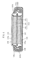
- An electric double layer capacitor comprises, as illustrated in Fig. 1, an electrode unit 10 having a first polarizable electrode 1 (first electrode) made of activated carbon, a second polarizable electrode 2 (second electrode) also made of activated carbon, and a separator 3 interposed therebetween.
- the first polarizable electrode 1 and the second polarizable electrode 2 are disposed so as to oppose each other across the separator 3.
- the electrode unit 10 is impregnated with an electrolyte solution in which triethylmethylammonium tetrafluoroborate, which serves as a supporting salt, is dissolved in a mixed organic solvent of propylene carbonate and sulfolane.
- the first polarizable electrode 1 is electrically connected via a first conductive current collector 6 to an external lid 4 serving as the cathode terminal
- the second polarizable electrode 2 is electrically connected via a second conductive current collector 7 to an external case 5 serving as the anode terminal.
- the external case 5 and the external lid 4 are made of stainless steel, and the electrode unit 10 is accommodated in the accommodating space defined by the external case 5 and the external lid 4.
- the external lid 4 has a shallow dish-like shape, and it comprises, specifically, a top wall 4a, a first circumferential wall 4b having a smaller diameter and adjoining the peripheral edge of the top wall 4a, and a second circumferential wall 4c having a larger diameter and adjoining the first circumferential wall 4b.
- the external case 5 has a shallow dish-like shape, and it comprises, specifically, a bottom wall 5a and a circumferential wall 5b adjoining the peripheral edge of the bottom wall 5a.
- the second circumferential wall 4c of the external lid 4 extends substantially linearly toward the bottom wall 5a of the external case 5, and unlike the conventional case, no folded part is formed at the edge part of the second circumferential wall 4c.
- the electric double layer capacitor of the present invention is designed so that the thickness of the external lid 4 is greater than the thickness of the external case 5 (specifically, the thickness of the external lid 4 is 0.2 mm, and the thickness of the external case 5 is 0.15 mm), and therefore, the strength of the external lid 4 becomes sufficiently large even when no folded part is provided at the edge part of the second circumferential wall 4c. Furthermore, in comparison with the case in which a folded part is provided, the space in which the polarizable electrodes 1 and 2 are to be disposed can be made larger corresponding to the thickness of the folded part. As a result, the capacitance can be increased.
- an electrically insulative gasket 8 is disposed between the inner surface of the circumferential wall 5b and the outer surfaces of the first circumferential wall 4b and the second circumferential wall 4c, so that the accommodating space defined by the external case 5 and the external lid 4 is hermetically closed by bending an open end part 5c of the external case 5 inwardly.
- the electric double layer capacitor of the present invention is configured so that the open end edge 4d of the external lid 4 (equivalent to the extending edge of the circumferential wall) is buried in the gasket 8, in addition to the configuration in which no folded part is provided.
- This configuration allows the portion of the circumferential wall engaged with the gasket 8 to be greater than the conventional product that is provided with the folded part, and thus makes it possible to further improve the hermeticity of the accommodating space formed by the external case 5 and the external lid 4.
- the ratio of the thicknesses of the external lid 4 and the external case 5 be 1.1 : 1 to 2 : 1. This restriction is made for the following reason. Specifically, if the external lid 4 is thinner than the thickness defined by the foregoing ratio, the strength of the external lid 4 is too weak. As a consequence, the hermeticity may degrade due to, for example, crimping of the external lid 4 in the process step of bending the open end part 5d of the external case 5 inwardly to hermetically close the accommodating space formed by the external case 5 and the external lid 4. On the other hand, if the external lid 4 is thicker than the thickness defined by the foregoing ratio, the space formed by the external lid 4 and the external case 5 is so narrow that the effect of capacitance increase may reduce.
- the electric double layer capacitor is fabricated in the following manner.
- Activated carbon, acetylene black, and polytetrafluoroethylene are mixed at a weight ratio of 90 : 5 : 5.
- the resultant mixture is shaped into a disk-like shape with a diameter of 2.2 mm and a thickness of 0.5 mm, and thereafter vacuum dried at 150°C for 2 hours, to thus prepare the first polarizable electrode 1 and the second polarizable electrode 2.
- An electrolyte solution is prepared by dissolving triethylmethylammonium tetrafluoroborate, which is a supporting salt, into an organic mixed solvent of a 50 : 50 volume ratio mixture of propylene carbonate and sulfolane at a concentration of 1.0 mole/liter.
- a conductive coating (made of a mixture of graphite powder and water glass), which later forms the current collectors 6 and 7, is applied onto the inner surface of the external lid 4 of the top wall 4a and onto the inner surface of the bottom wall 5a of the external case 5.
- the first polarizable electrode 1 is disposed on top of the conductive coating that has been applied to the top wall 4a of the external lid 4, and the second polarizable electrode 2 is disposed on top of the conductive coating that has been applied to the bottom wall 5a of the external case 5; thereafter, the electrodes with the conductive coating are heated to thereby form the first and second current collectors 6 and 7.
- the separator 3 is placed onto the second polarizable electrode 2, and thereafter, the electrolyte solution is impregnated in the first polarizable electrode 1, the second polarizable electrode 2, and the separator 3.
- the external lid 4 is disposed in the external case 5 so that the first polarizable electrode 1 is arranged on the second polarizable electrode 2 with the separator 3 interposed therebetween.
- the gasket 8 made of polyether ether ketone is disposed between the inner surface of the circumferential wall 5b of the external case 5 and the outer surfaces of the first circumferential wall 4b and the second circumferential wall 4c of the external lid 4.
- the open end part 5c of the external case 5 is bent inwardly and thereby the open end edge 4d of the external lid 4 is buried into the gasket 8, to hermetically seal the accommodating space defined by the external case 5 and the external lid 4.
- the button-type electric double layer capacitor is fabricated.
- Capacitor A of the invention The button-type electric double layer capacitor thus fabricated is hereinafter referred to as Capacitor A of the invention.
- Samples of the conventional button-type electric double layer capacitor were fabricated in the same manner as in the Example described above, except that a folded part was provided at the edge of the external lid and that the polarizable electrodes had a diameter of 2.0 mm and a thickness of 0.5 mm.
- Comparative Capacitor Z The button-type electric double layer capacitor thus fabricated is hereinafter referred to as Comparative Capacitor Z.
- Capacitor A of the invention exhibited a higher capacitance than Comparative Capacitor Z. This is because Capacitor A of the invention made it possible to more effectively utilize the accommodating space formed by the external lid 4 that has conventionally been unable to be utilized because of the presence of the folded part, so it became possible to dispose the polarizable electrodes 1 and 2 with a larger size.
- the present invention makes it possible to improve the strength of the external lid 4 by making the thickness of the external lid 4 greater than the thickness of the external case 5. Furthermore, fitting the open end edge 4d of the external lid 4 into the gasket 8 toward the bottom wall 5a of the external case 5 allows the portion of the open end edge 4d engaged with the gasket 8 to be greater than Comparative Example, which is provided with a folded part. Therefore, the hermeticity of the accommodating space formed by the external case 5 and the external lid 4 can be enhanced.
Landscapes
- Engineering & Computer Science (AREA)
- Power Engineering (AREA)
- Microelectronics & Electronic Packaging (AREA)
- Electric Double-Layer Capacitors Or The Like (AREA)
Abstract
Description
- The present invention relates to a button-shaped electric double layer capacitor comprising a pair of electrodes opposing each other with a separator interposed therebetween in which an electrolyte solution is impregnated.
- A button-shaped electric double layer capacitor as shown in Fig. 4 is well known. The electric double layer capacitor has an
electrode unit 110 in which a firstpolarizable electrode 101 made of, for example, activated carbon, and a secondpolarizable electrode 102 also made of, for example, activated carbon, are opposed to each other across aseparator 103 interposed between the electrodes. Theelectrode unit 110 is impregnated with an electrolyte solution. The firstpolarizable electrode 101 is electrically connected via a firstcurrent collector 106 to anexternal lid 104, which serves as the cathode terminal, and the secondpolarizable electrode 102 is electrically connected via a secondcurrent collector 107 to anexternal case 105, which serves as the anode terminal. Theelectrode unit 110 is accommodated in an accommodating space defined by theexternal case 105 and theexternal lid 104. - The
external lid 104 has a shallow dish-like shape. Specifically, it comprises atop wall 104a, a firstcircumferential wall 104b having a smaller diameter and adjoining the peripheral edge of thetop wall 104a, and a secondcircumferential wall 104c having a larger diameter and adjoining the firstcircumferential wall 104b. On the other hand, theexternal case 105 has a shallow dish-like shape, and specifically, it comprises abottom wall 105a and acircumferential wall 105b adjoining the peripheral edge of thebottom wall 105a. An electricallyinsulative gasket 108 is disposed between the inner surface of thecircumferential wall 105b and the outer surfaces of the firstcircumferential wall 104b and the secondcircumferential wall 104c. Anopen end part 105c of theexternal case 105 is bent inwardly, whereby the accommodating space defined by theexternal case 105 and theexternal lid 104 is hermetically closed. A foldedpart 104d is formed at the edge part of the secondcircumferential wall 104c. The foldedpart 104d serves to improve the strength of theexternal lid 104, and to apply pressure to thegasket 108 so that the hermeticity can be improved. (See, for example,page 2 and Fig. 3 ofJapanese Published Unexamined Patent Application No. 8-222192 - The presence of the folded
part 104d, however, narrows the accommodating space, which is formed by theexternal lid 104 and theexternal case 105. Specifically, the diameter of the firstcircumferential wall 104b of theexternal lid 104 needs to be made smaller corresponding to the thickness increase of the external lid, which is due to the provision of the foldedpart 104d. Therefore, the diameter of theelectrode unit 110 placed in the accommodating space cannot be made large, so the capacitance of the electric double layer capacitor cannot be increased if the size of the electric double layer capacitor is fixed. - In view of the foregoing problem, it is an object of the present invention to provide an electric double layer capacitor that has a large capacitance and achieves good productivity.
- In order to accomplish the foregoing and other objects, the present invention provides an electric double layer capacitor comprising: a) an electrode unit having a separator, first and second electrodes opposing each other across the separator therebetween, and an electrolyte solution impregnated in the electrode unit; b) an external lid, formed in a flattened U-shape in cross section, having a top wall and a circumferential wall adjoining the peripheral edge of the top wall; c) an external case, formed in a flattened U-shape in cross section, having a bottom wall and a circumferential wall adjoining the peripheral edge of the bottom wall; and d) a gasket disposed between an outer surface of the external lid and an inner surface of the external case, the electric double layer capacitor being configured so that the external case has an open end part that is bent inwardly with the external lid and the external case being disposed so that inner surfaces of the top wall and the bottom wall face each other, to hermetically close an accommodating space, formed by the external case and the external lid, for accommodating the electrode unit, wherein: the thickness of at least the circumferential wall of the external lid is greater than the thickness of the external case; and the circumferential wall of the external lid extends substantially linearly toward the bottom wall of the external case, and the extending edge of the circumferential wall of the external lid is buried in the gasket.
- The configuration in which the thickness of at least the circumferential wall of the external lid is greater than the thickness of the external case as described above allows the strength of the external lid to be greater, and therefore, can prevent deformation of the external lid such as crimping even when a large pressure acts on the external lid in the process step of hermetically closing the accommodating space formed by the external case and the external lid by bending the open end part of the external case inwardly. As a result, hermeticity of the external case and the external lid can be improved. In addition, the configuration in which the circumferential wall of the external lid extends substantially linearly toward the bottom wall of the external case (in other words, the configuration in which no folded part is provided at the edge of the circumferential wall of the external lid) allows the space in which both electrodes are disposed to be greater than that of the conventional products, making it possible to increase the capacitance. Moreover, the configuration in which the extending edge of the circumferential wall of the external lid is buried in the gasket allows the portion of the circumferential wall engaged with the gasket to be greater than the conventional product in which the folded part is provided, further improving the hermeticity of the accommodating space formed by the external case and the external lid. It should be noted that the configuration in which "the thickness of at least the circumferential wall of the external lid is greater than the thickness of the external case" is not limited to the configuration in which the top wall and the circumferential wall of the external lid (the entire external lid) has a uniform thickness and the thickness is greater than the thickness of the external case, but is intended to include such a configuration in which the thickness of the circumferential wall of the external lid is greater than the thickness of the external case and the thickness of the top wall of the external lid is smaller than the thickness of the external case.
- In the present invention, the ratio between the thickness of at least the circumferential wall of the external lid and the thickness of the external case may be restricted to 1.1 : 1 to 2 : 1. This restriction is made for the following reason. Specifically, if the external lid is thinner than the thickness defined by the foregoing ratio, strength of the external lid becomes too weak. As a consequence, in the process step of bending the open end part of the external case inwardly to hermetically close the accommodating space defined by the external case and the external lid, the hermeticity may degrade due to, for example, crimping of the external lid. On the other hand, if the external lid is thicker than the thickness defined by the foregoing ratio, the space formed by the external lid and the external case is so narrow that the effect of capacitance increase may reduce.
- The circumferential wall of the external lid may comprise a first circumferential wall having a smaller diameter and adjoining the peripheral edge of the top wall, and a second circumferential wall having a larger diameter and adjoining the first circumferential wall.
- In the present invention, it is preferable that the extending edge of the circumferential wall of the external lid have, at a bottom surface thereof (at a bottom surface of the second circumferential wall when the circumferential wall of the external lid comprises the first circumferential wall and the second circumferential wall), a recessed part into which the gasket fits. By employing this configuration, the gasket is allowed to fit into the recessed part, so the hermeticity can be enhanced. It is preferable that the recessed part have a depth of from 5 µm to 50 µm. The reason is as follows. When the depth of the recessed part is equal to or greater than 5 µm, the gasket will more firmly fit into the recessed part, further improving the hermeticity. On the other hand, if the depth of the recessed part is greater than 50 µm, the gasket may be damaged in the process step of bending the open end part of the external case inwardly, which may cause cracks.
- It is preferable that the gasket comprises as its main component polyether ether ketone, which has high resistance to electrolyte solution and high heat resistance. In addition, it is preferable that the gasket is heat-treated at a temperature higher than a solder melting point (for example, 260°C). The reason is that heat-treating the gasket in advance at a temperature higher than the heating temperature in the reflow soldering process promotes crystallization of the gasket, thereby allowing the gasket to become more stable physically, and thus, adhesiveness of the gasket to the external lid and the external case improves.
- By employing the present invention, hermeticity of the accommodating space formed by the external lid and the external case of the electric double layer capacitor can be enhanced without narrowing the accommodating space formed by the external lid and the external case.
-
- Fig. 1 is a cross-sectional view illustrating an electric double layer capacitor according to the present invention;
- Fig. 2 is a cross-sectional view illustrating an electric double layer capacitor according to a modified example of the present invention;
- Fig. 3A is a cross-sectional view illustrating a portion near the extending edge of the external lid in another modified example;
- Fig. 3B is a cross-sectional view illustrating a portion near the extending edge of the external lid in yet another modified example;
- Fig. 3C is a cross-sectional view illustrating a portion near the extending edge of the external lid in still another modified example; and
- Fig. 4 is a cross-sectional view illustrating a conventional electric double layer capacitor.
- Hereinbelow, the present invention is described in further detail based on preferred embodiments thereof. It should be construed, however, that the present invention is not limited to the following preferred embodiments but various changes and modifications are possible without departing from the scope of the invention.
- An electric double layer capacitor according to the present invention comprises, as illustrated in Fig. 1, an
electrode unit 10 having a first polarizable electrode 1 (first electrode) made of activated carbon, a second polarizable electrode 2 (second electrode) also made of activated carbon, and aseparator 3 interposed therebetween. The firstpolarizable electrode 1 and the secondpolarizable electrode 2 are disposed so as to oppose each other across theseparator 3. Theelectrode unit 10 is impregnated with an electrolyte solution in which triethylmethylammonium tetrafluoroborate, which serves as a supporting salt, is dissolved in a mixed organic solvent of propylene carbonate and sulfolane. - The first
polarizable electrode 1 is electrically connected via a first conductivecurrent collector 6 to anexternal lid 4 serving as the cathode terminal, and the secondpolarizable electrode 2 is electrically connected via a second conductivecurrent collector 7 to anexternal case 5 serving as the anode terminal. Theexternal case 5 and theexternal lid 4 are made of stainless steel, and theelectrode unit 10 is accommodated in the accommodating space defined by theexternal case 5 and theexternal lid 4. Theexternal lid 4 has a shallow dish-like shape, and it comprises, specifically, atop wall 4a, a firstcircumferential wall 4b having a smaller diameter and adjoining the peripheral edge of thetop wall 4a, and a secondcircumferential wall 4c having a larger diameter and adjoining the firstcircumferential wall 4b. Likewise, theexternal case 5 has a shallow dish-like shape, and it comprises, specifically, abottom wall 5a and acircumferential wall 5b adjoining the peripheral edge of thebottom wall 5a. - The second
circumferential wall 4c of theexternal lid 4 extends substantially linearly toward thebottom wall 5a of theexternal case 5, and unlike the conventional case, no folded part is formed at the edge part of the secondcircumferential wall 4c. The electric double layer capacitor of the present invention is designed so that the thickness of theexternal lid 4 is greater than the thickness of the external case 5 (specifically, the thickness of theexternal lid 4 is 0.2 mm, and the thickness of theexternal case 5 is 0.15 mm), and therefore, the strength of theexternal lid 4 becomes sufficiently large even when no folded part is provided at the edge part of the secondcircumferential wall 4c. Furthermore, in comparison with the case in which a folded part is provided, the space in which thepolarizable electrodes - In addition, an electrically
insulative gasket 8 is disposed between the inner surface of thecircumferential wall 5b and the outer surfaces of the firstcircumferential wall 4b and the secondcircumferential wall 4c, so that the accommodating space defined by theexternal case 5 and theexternal lid 4 is hermetically closed by bending anopen end part 5c of theexternal case 5 inwardly. - It should be noted that the electric double layer capacitor of the present invention is configured so that the
open end edge 4d of the external lid 4 (equivalent to the extending edge of the circumferential wall) is buried in thegasket 8, in addition to the configuration in which no folded part is provided. This configuration allows the portion of the circumferential wall engaged with thegasket 8 to be greater than the conventional product that is provided with the folded part, and thus makes it possible to further improve the hermeticity of the accommodating space formed by theexternal case 5 and theexternal lid 4. - It is preferable that the ratio of the thicknesses of the
external lid 4 and theexternal case 5 be 1.1 : 1 to 2 : 1. This restriction is made for the following reason. Specifically, if theexternal lid 4 is thinner than the thickness defined by the foregoing ratio, the strength of theexternal lid 4 is too weak. As a consequence, the hermeticity may degrade due to, for example, crimping of theexternal lid 4 in the process step of bending the open end part 5d of theexternal case 5 inwardly to hermetically close the accommodating space formed by theexternal case 5 and theexternal lid 4. On the other hand, if theexternal lid 4 is thicker than the thickness defined by the foregoing ratio, the space formed by theexternal lid 4 and theexternal case 5 is so narrow that the effect of capacitance increase may reduce. - The electric double layer capacitor is fabricated in the following manner.
- Activated carbon, acetylene black, and polytetrafluoroethylene are mixed at a weight ratio of 90 : 5 : 5. The resultant mixture is shaped into a disk-like shape with a diameter of 2.2 mm and a thickness of 0.5 mm, and thereafter vacuum dried at 150°C for 2 hours, to thus prepare the first
polarizable electrode 1 and the secondpolarizable electrode 2. - An electrolyte solution is prepared by dissolving triethylmethylammonium tetrafluoroborate, which is a supporting salt, into an organic mixed solvent of a 50 : 50 volume ratio mixture of propylene carbonate and sulfolane at a concentration of 1.0 mole/liter.
- First, a conductive coating (made of a mixture of graphite powder and water glass), which later forms the
current collectors external lid 4 of thetop wall 4a and onto the inner surface of thebottom wall 5a of theexternal case 5. Next, the firstpolarizable electrode 1 is disposed on top of the conductive coating that has been applied to thetop wall 4a of theexternal lid 4, and the secondpolarizable electrode 2 is disposed on top of the conductive coating that has been applied to thebottom wall 5a of theexternal case 5; thereafter, the electrodes with the conductive coating are heated to thereby form the first and secondcurrent collectors separator 3 is placed onto the secondpolarizable electrode 2, and thereafter, the electrolyte solution is impregnated in the firstpolarizable electrode 1, the secondpolarizable electrode 2, and theseparator 3. Thereafter, theexternal lid 4 is disposed in theexternal case 5 so that the firstpolarizable electrode 1 is arranged on the secondpolarizable electrode 2 with theseparator 3 interposed therebetween. At this time, thegasket 8 made of polyether ether ketone is disposed between the inner surface of thecircumferential wall 5b of theexternal case 5 and the outer surfaces of the firstcircumferential wall 4b and the secondcircumferential wall 4c of theexternal lid 4. Subsequently, theopen end part 5c of theexternal case 5 is bent inwardly and thereby theopen end edge 4d of theexternal lid 4 is buried into thegasket 8, to hermetically seal the accommodating space defined by theexternal case 5 and theexternal lid 4. Thus, the button-type electric double layer capacitor is fabricated. - Samples of the above-described button-type electric double layer capacitor were prepared in the just-described manner.
- The button-type electric double layer capacitor thus fabricated is hereinafter referred to as Capacitor A of the invention.
- Samples of the conventional button-type electric double layer capacitor were fabricated in the same manner as in the Example described above, except that a folded part was provided at the edge of the external lid and that the polarizable electrodes had a diameter of 2.0 mm and a thickness of 0.5 mm.
- The button-type electric double layer capacitor thus fabricated is hereinafter referred to as Comparative Capacitor Z.
- The capacitances of the samples of Capacitor A of the invention and Comparative Capacitor Z were measured, and the mean values were obtained. The results are shown in Table 1 below. The number of the samples was 50 for each of the capacitors.
TABLE 1 Capacitance (mF) Capacitor A 63 Comparative Capacitor Z 51 - As clearly seen from Table 1, Capacitor A of the invention exhibited a higher capacitance than Comparative Capacitor Z. This is because Capacitor A of the invention made it possible to more effectively utilize the accommodating space formed by the
external lid 4 that has conventionally been unable to be utilized because of the presence of the folded part, so it became possible to dispose thepolarizable electrodes - Moreover, the present invention makes it possible to improve the strength of the
external lid 4 by making the thickness of theexternal lid 4 greater than the thickness of theexternal case 5. Furthermore, fitting theopen end edge 4d of theexternal lid 4 into thegasket 8 toward thebottom wall 5a of theexternal case 5 allows the portion of theopen end edge 4d engaged with thegasket 8 to be greater than Comparative Example, which is provided with a folded part. Therefore, the hermeticity of the accommodating space formed by theexternal case 5 and theexternal lid 4 can be enhanced. -
- (1) Although the foregoing example has described that the circumferential wall of the
external lid 4 is made of the firstcircumferential wall 4b and the secondcircumferential wall 4c with different diameters, it is possible to construct the circumferential wall with a uniform diameter.
In addition, although the foregoing Example has described a configuration in which the thickness of the entire external lid 4 (which is made of thetop wall 4a, the firstcircumferential wall 4b, and the secondcircumferential wall 4c) is greater than the thickness of theexternal case 5, it is also possible to adopt a configuration in which, as illustrated in Fig. 2, the firstcircumferential wall 4b and the secondcircumferential wall 4c have the same thickness that is greater than the thickness of theexternal case 5 while the thickness of thetop wall 4a is smaller than the thickness of theexternal case 5. - (2) The bottom surface of the
open end edge 4d of the external lid 4 (equivalent to the bottom surface of the secondcircumferential wall 4c) may be provided with a recessedpart 15, as illustrated in Figs. 3A to 3C. This configuration enables the size of thepolarizable electrodes gasket 8 fits into the recessedpart 15 so that the hermeticity can improve. The recessedpart 15 may be processed into various shapes including a substantially U-shaped cross-sectional shape shown in Fig. 3A, a substantially W-shaped cross-sectional shape shown in Fig. 3B, and a substantially V-shaped cross-sectional shape shown in Fig. 3C. - (3) It is preferable that the depth of the recessed
part 15 be in the range of from 5 µm to 50 µm. This restriction is made for the following reason. When the depth of the recessedpart 15 is 5 µm or greater, thegasket 8 will more firmly fit into the recessedpart 15, further enhancing the hermeticity. On the other hand, if the depth of the recessedpart 15 is greater than 50 µm, thegasket 8 may be damaged in the process step of bending theopen end part 5b inwardly, which becomes a cause of cracks. - (4) Examples of the material for the
separator 3 used in the present invention include, but are not limited to, glass fibers and resins such as polyphenylene sulfide, polyethylene terephthalate, polyamide, and polyimide, to form an insulative film that has a large ion permeability and also achieves predetermined mechanical strengths. In addition, the pore size of theseparator 3 may be any size as long as it falls within the range that is generally employed for capacitors; for example, the pore size may be in the range of from 0.01 µm to 5 µm. In addition, the thickens of theseparator 3 may be any thickness that is commonly employed, for example, in the range of from 10 µm to 300 µm. - (5) The
polarizable electrodes
The active material may be made of powdery activated carbon that is obtained by subjecting a material such as sawdust, coconut shell, and pitch to an activation process. It is also possible to use a material obtained by subjecting a fiber material such as phenol-based fiber, rayon-based fiber, acryl-based fiber, and pitch-based fiber to an infusible process and a carbonization activation process, thereby producing activated carbon or activated carbon fiber, and forming the resultant material into a felt, fiber, paper, or sinter form. Other usable examples include metallic compounds and carbon materials such as carbon nanotubes.
The binder agent may be any binder agent that is commonly used for electric double layer capacitors. Examples include polytetrafluoroethylene, polyvinylidene fluoride, polyvinyl pyrrolidone, polyvinyl chloride, polyethylene, polypropylene, polyfluoroethylenepropylene, ethylene-propylene-diene terpolymer, styrene-butadiene rubber, carboxymethylcellulose, and fluorocarbon rubber.
The conductive agent may be any conductive agent that is commonly used for electric double layer capacitors; examples include natural graphite such as flaked graphite and earthy graphite, artificial graphite, carbon black, acetylene black, Ketjen Black, and carbon fibers. - (6) The electrolyte solution may be made of any materials that have conventionally been used. For example, the foregoing Example used an electrolyte solution in which a supporting salt was dissolved in an organic solvent containing propylene carbonate. Here, when propylene carbonate is mixed with another solvent, the other solvent is not limited to sulfolane mentioned above, but may be various other solvents such as cyclic esters, chain esters, cyclic ethers, and chain ethers.
Specific examples include: ethylene carbonate, butylene carbonate, dimethyl carbonate, diethyl carbonate, γ-butyrolactone, 2-methyl-γ-butyrolactone, acetyl-γ-butyrolactone, γ-valerolactone, 1,2-dimethoxyethane, 1,2-ethoxyethane, diethyl ether, diethylene glycol diethyl ether, triethylene glycol diethyl ether, ethylene glycol dialkyl ether, diethylene glycol dialkyl ether, triethylen eglycol dialkyl ether, tetraethylene glycol dialkyl ether, dipropyl carbonate, methyl ethyl carbonate, methyl butyl carbonate, ethylpropyl carbonate, butylpropyl carbonate, propionic acid alkyl ester, malonic acid dialkyl ester, acetic acid alkyl ester, tetrahydrofuran (THF), alkyltetrahydrofuran, dialkyltetrahydrofuran, alkoxytetrahydrofuran, dialkoxytetrahydrofuran, 1,3-dioxolane, alkyl-1,3-dioxolane, 1,4-dioxolane, 2-methyltetrahydrofuran, dimethyl sulfoxide, 1,3-dioxolane, formamide, dimethylformamide, dioxolane, acetonitrile, nitromethane, methyl formate, methyl acetate, methyl propionate, ethyl propionate, trialkyl phosphate, maleic anhydride, and 3-methylsulfolane, all of which may be used either alone or in combination. In particular, a mixture of propylene carbonate and sulfolane, as in Example above, is preferable because it shows good heat resistance.
A preferable supporting salt is tetraethylammonium tetrafluoroborate or triethylmethylammonium tetrafluoroborate. However, it is also possible to use (C2H5)4PBF4, (C3H7)4PBF4, (C2H5)4PPF6, (C2H5)4PCF3SO4, (C2H5)4NPF6, LiClO4, LiPF6, LiBF4, and LiN(CF3SO2)2, which may be used either alone or in combination. - (7) In order to further enhance the sealing performance of the
gasket 8, it is possible that the gasket is coated with a liquid sealant made from at least one material among hydrocarbon-based or fluorine-based oil such as asphalt and butyl rubber, chlorosulfonated polyethylene, and epoxy resin, diluted by a solvent as necessary. - Only selected embodiments have been chosen to illustrate the present invention. To those skilled in the art, however, it will be apparent from the foregoing disclosure that various changes and modifications can be made herein without departing from the scope of the invention as defined in the appended claims. Furthermore, the foregoing description of the embodiments according to the present invention is provided for illustration only, and not for limiting the invention as defined by the appended claims and their equivalents.
Claims (8)
- An electric double layer capacitor comprising a) an electrode unit having a separator, first and second electrodes opposing each other across the separator therebetween, and an electrolyte solution impregnated in the electrode unit; b) an external lid, formed in a flattened U-shape in cross section, having a top wall and a circumferential wall adjoining the peripheral edge of the top wall; c) an external case, formed in a flattened U-shape in cross section, having a bottom wall and a circumferential wall adjoining the peripheral edge of the bottom wall; and d) a gasket disposed between an outer surface of the external lid and an inner surface of the external case, the electric double layer capacitor being configured so that the external case has an open end part that is bent inwardly with the external lid and the external case being disposed so that inner surfaces of the top wall and the bottom wall face each other, to hermetically close an accommodating space, formed by the external case and the external lid, for accommodating the electrode unit, characterized in that:the thickness of at least the circumferential wall of the external lid is greater than the thickness of the external case; andthe circumferential wall of the external lid extends substantially linearly toward the bottom wall of the external case, and the extending edge of the circumferential wall of the external lid is buried in the gasket.
- The electric double layer capacitor according to claim 1, wherein the ratio between the thickness of at least the circumferential wall of the external lid and the thickness of the external case is 1.1 : 1 to 2 : 1.
- The electric double layer capacitor according to claim 1 or 2, wherein the circumferential wall of the external lid comprises a first circumferential wall having a smaller diameter and adjoining the peripheral edge of the top wall, and a second circumferential wall having a larger diameter and adjoining the first circumferential wall.
- The electric double layer capacitor according to claim 3, wherein the extending edge has, at a bottom surface thereof, a recessed part into which the gasket fits.
- The electric double layer capacitor according to claim 4, wherein the recessed part has a depth of from 5 µm to 50 µm.
- The electric double layer capacitor according to any one of claims 1 through 5, wherein the main component of the gasket is polyether ether ketone.
- The electric double layer capacitor according to any one of claims 1 through 6, wherein the gasket is heat-treated at a temperature higher than a solder melting point.
- The electric double layer capacitor according to claim 7, wherein the temperature is 260°C.
Applications Claiming Priority (1)
| Application Number | Priority Date | Filing Date | Title |
|---|---|---|---|
| JP2005247172A JP2007066943A (en) | 2005-08-29 | 2005-08-29 | Electric double-layer capacitor |
Publications (1)
| Publication Number | Publication Date |
|---|---|
| EP1777715A1 true EP1777715A1 (en) | 2007-04-25 |
Family
ID=37810896
Family Applications (1)
| Application Number | Title | Priority Date | Filing Date |
|---|---|---|---|
| EP06017805A Withdrawn EP1777715A1 (en) | 2005-08-29 | 2006-08-25 | Electric double layer capacitor |
Country Status (4)
| Country | Link |
|---|---|
| US (1) | US20070053138A1 (en) |
| EP (1) | EP1777715A1 (en) |
| JP (1) | JP2007066943A (en) |
| CN (1) | CN1925077A (en) |
Families Citing this family (3)
| Publication number | Priority date | Publication date | Assignee | Title |
|---|---|---|---|---|
| US20120033346A1 (en) * | 2010-08-05 | 2012-02-09 | Samsung Electro-Mechanics Co., Ltd. | Energy storage device |
| TWI517192B (en) * | 2013-06-28 | 2016-01-11 | 逢甲大學 | Packaging structures of an energy storage device |
| JP7077147B2 (en) * | 2018-05-31 | 2022-05-30 | 株式会社東芝 | Electronics |
Citations (4)
| Publication number | Priority date | Publication date | Assignee | Title |
|---|---|---|---|---|
| JPH08298232A (en) * | 1995-04-25 | 1996-11-12 | Kureha Chem Ind Co Ltd | Electric double layer capacitor |
| US6301093B1 (en) * | 1999-01-14 | 2001-10-09 | Honda Giken Kogyo Kabushiki Kaisha | Electrochemical capacitor |
| EP1324360A2 (en) * | 2001-12-18 | 2003-07-02 | Camatech Co., Ltd. | Electric double layer capacitor and method of fabricating the same |
| EP1724794A1 (en) * | 2004-03-09 | 2006-11-22 | Sanyo Electric Co., Ltd. | Electric double-layer capacitor |
Family Cites Families (4)
| Publication number | Priority date | Publication date | Assignee | Title |
|---|---|---|---|---|
| WO1999025039A1 (en) * | 1997-11-10 | 1999-05-20 | Nippon Zeon Co., Ltd. | Binder containing vinyl alcohol polymer, slurry, electrode, and secondary battery with nonaqueous electrolyte |
| WO2005038835A1 (en) * | 2003-10-20 | 2005-04-28 | Sanyo Electric Co., Ltd. | Electric double layer capacitor |
| CN1321469C (en) * | 2004-03-04 | 2007-06-13 | 松下电器产业株式会社 | Square gas battery |
| JP2007005717A (en) * | 2005-06-27 | 2007-01-11 | Sanyo Electric Co Ltd | Electrochemical element |
-
2005
- 2005-08-29 JP JP2005247172A patent/JP2007066943A/en not_active Withdrawn
-
2006
- 2006-08-25 EP EP06017805A patent/EP1777715A1/en not_active Withdrawn
- 2006-08-28 US US11/467,744 patent/US20070053138A1/en not_active Abandoned
- 2006-08-28 CN CNA2006101257719A patent/CN1925077A/en active Pending
Patent Citations (4)
| Publication number | Priority date | Publication date | Assignee | Title |
|---|---|---|---|---|
| JPH08298232A (en) * | 1995-04-25 | 1996-11-12 | Kureha Chem Ind Co Ltd | Electric double layer capacitor |
| US6301093B1 (en) * | 1999-01-14 | 2001-10-09 | Honda Giken Kogyo Kabushiki Kaisha | Electrochemical capacitor |
| EP1324360A2 (en) * | 2001-12-18 | 2003-07-02 | Camatech Co., Ltd. | Electric double layer capacitor and method of fabricating the same |
| EP1724794A1 (en) * | 2004-03-09 | 2006-11-22 | Sanyo Electric Co., Ltd. | Electric double-layer capacitor |
Also Published As
| Publication number | Publication date |
|---|---|
| JP2007066943A (en) | 2007-03-15 |
| US20070053138A1 (en) | 2007-03-08 |
| CN1925077A (en) | 2007-03-07 |
Similar Documents
| Publication | Publication Date | Title |
|---|---|---|
| US8273263B2 (en) | Ionic compound | |
| US7974074B2 (en) | Electric double-layered capacitor | |
| US20120243145A1 (en) | Electric double layer capacitor | |
| JP2002063934A (en) | Electrolytic solution and electrochemical element using it | |
| US8274780B2 (en) | Polarizable electrode for electric double layer capacitor and electric double layer capacitor using the same | |
| WO2007055392A1 (en) | Ionic compound | |
| JP2010040554A (en) | Coin type cell and method of manufacturing the same | |
| KR102028597B1 (en) | Current collector for Electrochemical energy storage device and Manufacturing method thereof | |
| JP2002190427A (en) | Electric double layer capacitor mountable by reflow soldering and method of manufacturing the same | |
| JPWO2008123286A1 (en) | Electric double layer capacitor | |
| US7110243B2 (en) | Electric double layer capacitor | |
| US20070053138A1 (en) | Electric double layer capacitor | |
| US7317608B2 (en) | Electric double layer capacitor | |
| KR20170070339A (en) | Electrochemical energy storage device and manufacturing method thereof | |
| JP3872182B2 (en) | Electric double layer capacitor | |
| JP2010245068A (en) | Electric double-layer capacitor | |
| JP2002056827A (en) | Non-aqueous electrolyte secondary battery | |
| US20190273284A1 (en) | Electrolyte for electrochemical device, electrolytic solution, and electrochemical device | |
| JP5039884B2 (en) | Electrochemical cell | |
| JP2004087825A (en) | Electric double layer capacitor | |
| JP2007067311A (en) | Electric double-layer capacitor | |
| JP2007019165A (en) | Accumulator device | |
| JP2004014989A (en) | Electric double layer capacitor | |
| JP4931480B2 (en) | ELECTROCHEMICAL ELEMENT AND ELECTRONIC DEVICE HAVING THE SAME | |
| JP2007180055A (en) | Electric double layer capacitor and mounting body thereof |
Legal Events
| Date | Code | Title | Description |
|---|---|---|---|
| PUAI | Public reference made under article 153(3) epc to a published international application that has entered the european phase |
Free format text: ORIGINAL CODE: 0009012 |
|
| AK | Designated contracting states |
Kind code of ref document: A1 Designated state(s): AT BE BG CH CY CZ DE DK EE ES FI FR GB GR HU IE IS IT LI LT LU LV MC NL PL PT RO SE SI SK TR |
|
| AX | Request for extension of the european patent |
Extension state: AL BA HR MK YU |
|
| 17P | Request for examination filed |
Effective date: 20071005 |
|
| AKX | Designation fees paid |
Designated state(s): AT BE BG CH CY CZ DE DK EE ES FI FR GB GR HU IE IS IT LI LT LU LV MC NL PL PT RO SE SI SK TR |
|
| STAA | Information on the status of an ep patent application or granted ep patent |
Free format text: STATUS: THE APPLICATION HAS BEEN WITHDRAWN |
|
| 18W | Application withdrawn |
Effective date: 20100618 |