EP1777606A2 - Power supply / cooling system - Google Patents
Power supply / cooling system Download PDFInfo
- Publication number
- EP1777606A2 EP1777606A2 EP06020168A EP06020168A EP1777606A2 EP 1777606 A2 EP1777606 A2 EP 1777606A2 EP 06020168 A EP06020168 A EP 06020168A EP 06020168 A EP06020168 A EP 06020168A EP 1777606 A2 EP1777606 A2 EP 1777606A2
- Authority
- EP
- European Patent Office
- Prior art keywords
- computer device
- cooling system
- housing
- fan
- airflow
- Prior art date
- Legal status (The legal status is an assumption and is not a legal conclusion. Google has not performed a legal analysis and makes no representation as to the accuracy of the status listed.)
- Ceased
Links
Images

Classifications
-
- G—PHYSICS
- G06—COMPUTING OR CALCULATING; COUNTING
- G06F—ELECTRIC DIGITAL DATA PROCESSING
- G06F1/00—Details not covered by groups G06F3/00 - G06F13/00 and G06F21/00
- G06F1/16—Constructional details or arrangements
- G06F1/20—Cooling means
- G06F1/203—Cooling means for portable computers, e.g. for laptops
-
- G—PHYSICS
- G06—COMPUTING OR CALCULATING; COUNTING
- G06F—ELECTRIC DIGITAL DATA PROCESSING
- G06F1/00—Details not covered by groups G06F3/00 - G06F13/00 and G06F21/00
- G06F1/16—Constructional details or arrangements
- G06F1/1613—Constructional details or arrangements for portable computers
- G06F1/1632—External expansion units, e.g. docking stations
-
- G—PHYSICS
- G06—COMPUTING OR CALCULATING; COUNTING
- G06F—ELECTRIC DIGITAL DATA PROCESSING
- G06F1/00—Details not covered by groups G06F3/00 - G06F13/00 and G06F21/00
- G06F1/16—Constructional details or arrangements
- G06F1/20—Cooling means
- G06F1/206—Cooling means comprising thermal management
Definitions
- Computer devices such as laptop or notebook computers, comprise a variety of different types of hardware and/or software including, for example, different types and functional levels of processors and graphic circuits.
- some computer devices are configured to operate at relatively high performance levels, thereby generating greater amounts of thermal energy and requiring additional power and/or systems to dissipate the thermal energy.
- new chassis designs to accommodate larger cooling systems and/or additional battery power to meet the operational parameters of the computer device increase costs associated with the computer device.
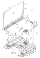
- FIGURE 1 is a diagram illustrating an embodiment of a power supply cooling system in accordance with the present invention.
- FIGURE 2 is a block diagram illustrating an embodiment of the power supply cooling system of FIGURE 1.
- FIGURES 1 and 2 of the drawings like numerals being used for like and corresponding parts of the various drawings.
- FIGURE 1 is a diagram illustrating an embodiment of a power supply cooling system 8 in accordance with the present invention.
- system 8 comprises a computer device 10 and a cooling system 12 removably couplable to computer device 10.
- computer device 10 comprises a laptop or notebook computer having a display member 16 rotatably coupled to a base member 18.
- computer device 10 may comprise other types of devices such as, but not limited to, tablet personal computers, personal digital assistants, or any other type of portable or non-portable computer device.
- Cooling system 12 is removably couplable to computer device 10 to provide additional power and/or cooling air to computer device 10.
- base member 18 of computer device 10 comprises a housing 20 having a working surface 22, a bottom surface 24, a front surface 26, a rear surface 28 and a pair of side surfaces 30 and 32.
- Display member 16 comprises a housing 34 having a display surface 36 and a rear surface 38.
- bottom surface 24 of base member 18 comprises at least one airflow inlet 48 having a plurality of apertures or openings 49 for receiving cooling air from cooling system 12, and a connector port 50 for communicatively engaging a correspondingly positioned connector port 52 on cooling system 12.
- housing 20 comprises at least one airflow outlet 54 disposed on rear surface 28 of base member 18 and having plurality of apertures or openings 55. Airflow into inlet 48 and exiting outlet 54 dissipate thermal energy generated by operational components of computer device 10 disposed within housing 20. It should be understood that outlet 54 may be otherwise located on base member 18 (e.g., disposed on surfaces 22, 24, 26, 30 and/or 32) and/or may be disposed on multiple surfaces of base member 18. Further, it should be understood that inlet 48 may be otherwise located on base member 18 corresponding to a source of cooling air provided by system 12.
- cooling system 12 comprises a housing 56 having a top surface 58, a bottom surface 60, a front surface 62, rear surfaces 64a, 64b and 64c, and a pair of side surfaces 66 and 68.
- cooling system 12 comprises a fan 70 for actively generating an airflow and a plurality of battery cells 74 disposed within housing 56.
- Cooling system 12 is configured to draw an airflow into housing 56 by fan 70 through a pair of inlets 76a and 76b each having apertures or openings 77 and located on respective rear surfaces 64a and 64c.
- cooling system 12 comprises at least one airflow outlet 82 having a plurality of apertures or openings 83 disposed on top surface 58 of housing 56 for cooperating with inlet 48 of computer device 10.
- fan 70 generates a positive airflow 78a and 78b through housing 56 from respective inlets 76a and 76b and following respective airflow paths 80a and 80b toward airflow outlet 82 and exhausts the airflow 78 through outlet 82.
- thermal energy generated by battery cells 74 and/or any other heat generating device disposed within housing 56 is dissipated through outlet 82.
- a greater or fewer number of inlets 76 can be disposed on rear surface 64 and/or on any other surface of cooling system 12 (e.g., surface 58, 60, 62, 66 and/or 68).
- cooling system 12 is removably couplable to computer device 10 by a locking system 84 such that outlet 82 of cooling system 12 is at least partially aligned with inlet 48 of base member 18, thereby providing an airflow from cooling system 12 to base member 18.
- a single inlet 48 and outlet 82 are illustrated.
- locking system 84 comprises a plurality of hooks 86 insertable into a plurality of correspondingly positioned openings 88 disposed on bottom surface 24 of base member 18 to securely fasten cooling system 12 to computer device 10.
- cooling system 12 may be coupled to base member 18 using other locations and/or surfaces of base member 18 (e.g., surfaces 22, 26, 28, 30 and/or 32).
- an engagement member 90 is used to facilitate a connection between outlet 82 of cooling system 12 and inlet 48 of computer device 10 to prevent or substantially prevent airflow leaks therefrom.
- Engagement member 90 may comprise an elastomeric member, protrusion or other device for facilitating engagement of outlet 82 to inlet 48.
- engagement member 90 is disposed on top surface 58 of cooling system 12 about a perimeter of outlet 82 such that when cooling system 12 is attached to computer device 10, engagement member 90 directs the airflow from outlet 82 to inlet 48, thereby eliminating or substantially reducing airflow loss between cooling system 12 and computer device 10. It should be understood that, alternatively or additionally, engagement member 90 may be installed on bottom surface 24 of base member 18.
- cooling system 12 In operation, when cooling system 12 is coupled to computer device 10, airflow 78 is directed into base member 18 through inlet 48 and exits base member 18 through outlet 54 to dissipate thermal energy generated by operational components of computer device disposed within base member 18.
- battery cells 74 of cooling system 12 are used to power cooling system 12 (e.g., providing power to fan 70 and/or other operational components of cooling system 12) and also provide power to computer device 10 (e.g., through connector ports 50 and 52).
- cooling system 12 may be otherwise powered (e.g., by internal and/or external batteries of computer device 10 or alternating current (AC) power obtained from an external outlet or AC adapter).
- AC alternating current
- computer device 10 is configured to operate in either a lightweight or low performance mode, where cooling system 12 is detached from computer device 10, or a high performance mode, where cooling system 12 is attached to computer device 10.
- a lightweight or low performance mode computer device 10 operates at a lower performance level, thereby utilizing less battery power and generating lower amounts of thermal energy. Accordingly, the need for additional cooling and/or power supplied via cooling system 12 is reduced.
- computer device 10 when computer device 10 is operated in the high performance mode, computer device 10 operates at a higher performance level, thereby utilizing additional power and generating increased levels of thermal energy.
- cooling system 12 enables computer device 10 to operate at higher performance levels by dissipating the additional thermal energy generated by computer device in the high performance mode and also providing an additional source of power to computer device 10 (e.g., via battery cells 74).
- cooling system 12 is configured as a cooling battery pack by providing both cooling and battery power functionality to computer device 10.
- FIGURE 2 is a block diagram illustrating system 8 comprising computer device 10 and cooling system 12 of FIGURE 1.
- computer device 10 comprises a processor 92 coupled to a memory 94, a sensor element 96, and connector port 50 for communicatively engaging connector port 52 of cooling system 12.
- computer device 10 also comprises a mode detector 97 and a thermal monitoring system 98.
- Mode detector 97 and thermal monitoring system 98 may comprise software, hardware, or a combination of software and hardware.
- mode detector 97 and thermal monitoring system 98 are illustrated as being stored in memory 94 so as to be accessible and/or executable by processor 92. However, it should be understood that mode detector 97 and/or thermal monitoring system 98 may be otherwise located or stored.
- mode detector 97 is used to detect whether cooling system 12 is attached to computer device 10. In some embodiments of the present invention, mode detector 97 detects whether cooling system 12 is attached to computer device 10 by determining an engagement status of connector port 50 with connector port 52 of cooling system 12, communication, or lack thereof, of communication and/or data signals between computer device 10 and cooling system 12, detection of a current or power supply at connector port 50, or otherwise. If mode detector 97 determines that cooling system 12 is not attached to computer device 10, computer device 10 is preferably configured to operate in the lightweight mode. If mode detector 97 detects that cooling system 12 is attached to computer device 10, computer device 10 is preferably configured to operate in the high performance mode.
- sensor element 96 is used to detect and/or measure a level of thermal energy generated by components of computer device 10 (e.g., a temperature sensor).
- Thermal monitoring system 98 monitors temperature information received from sensor element 96 and generates a signal that is processed by hardware, software, and/or a combination thereof, of computer device 10 (e.g., a basic input output system (BIOS), operating system or other hardware and/or software component of computer device 10) to control the speed of fan 70 and/or actuation/de-actuation of fan 70.
- BIOS basic input output system
- thermal monitoring system 98 controls and/or otherwise causes actuation of fan 70 and/or an increase in speed of fan 70, thereby increasing a level of thermal energy dissipation from within computer device 10.
- thermal monitoring system 98 controls and/or otherwise causes a decrease in fan 70 speed and/or de-actuation of fan 70.
- thermal monitoring system 98 is configured to actuate fan 70 at various intervals, at predetermined fan 70 speeds and/or for predetermined periods of time to dissipate thermal energy generated by operation of computer device 10.
- embodiments of the present invention provide a computer device 10 having a removably couplable cooling device 12 to dissipate heat from computer device 10 and provide power to computer device 10.
- Embodiments of the present invention enable computer device 10 to be manufactured smaller in size yet with high performance capabilities by providing a battery source with cooling-on-demand capabilities.
Landscapes
- Engineering & Computer Science (AREA)
- Theoretical Computer Science (AREA)
- Human Computer Interaction (AREA)
- Physics & Mathematics (AREA)
- General Engineering & Computer Science (AREA)
- General Physics & Mathematics (AREA)
- Computer Hardware Design (AREA)
- Cooling Or The Like Of Electrical Apparatus (AREA)
- Rectifiers (AREA)
- Secondary Cells (AREA)
Abstract
Description
- Computer devices, such as laptop or notebook computers, comprise a variety of different types of hardware and/or software including, for example, different types and functional levels of processors and graphic circuits. Thus, some computer devices are configured to operate at relatively high performance levels, thereby generating greater amounts of thermal energy and requiring additional power and/or systems to dissipate the thermal energy. To accommodate the increased operational and thermal dissipation needs of the computer device, new chassis designs to accommodate larger cooling systems and/or additional battery power to meet the operational parameters of the computer device increase costs associated with the computer device.
- For a more complete understanding of the present invention, and the objects and advantages thereof, reference is now made to the following descriptions taken in connection with the accompanying drawings in which:
- FIGURE 1 is a diagram illustrating an embodiment of a power supply cooling system in accordance with the present invention; and
- FIGURE 2 is a block diagram illustrating an embodiment of the power supply cooling system of FIGURE 1.
- The preferred embodiments of the present invention and the advantages thereof are best understood by referring to FIGURES 1 and 2 of the drawings, like numerals being used for like and corresponding parts of the various drawings.
- FIGURE 1 is a diagram illustrating an embodiment of a power
supply cooling system 8 in accordance with the present invention. In the embodiment illustrated in FIGURE 1,system 8 comprises acomputer device 10 and acooling system 12 removably couplable tocomputer device 10. In the embodiment illustrated in FIGURE 1,computer device 10 comprises a laptop or notebook computer having adisplay member 16 rotatably coupled to abase member 18. However, it should be understood thatcomputer device 10 may comprise other types of devices such as, but not limited to, tablet personal computers, personal digital assistants, or any other type of portable or non-portable computer device.Cooling system 12 is removably couplable tocomputer device 10 to provide additional power and/or cooling air tocomputer device 10. - In the embodiment illustrated in FIGURE 1,
base member 18 ofcomputer device 10 comprises ahousing 20 having a workingsurface 22, abottom surface 24, afront surface 26, arear surface 28 and a pair ofside surfaces Display member 16 comprises ahousing 34 having adisplay surface 36 and arear surface 38. In the embodiment illustrated in FIGURE 1,bottom surface 24 ofbase member 18 comprises at least oneairflow inlet 48 having a plurality of apertures oropenings 49 for receiving cooling air fromcooling system 12, and aconnector port 50 for communicatively engaging a correspondingly positionedconnector port 52 oncooling system 12. - In the embodiment illustrated in FIGURE 1,
housing 20 comprises at least oneairflow outlet 54 disposed onrear surface 28 ofbase member 18 and having plurality of apertures oropenings 55. Airflow intoinlet 48 and exitingoutlet 54 dissipate thermal energy generated by operational components ofcomputer device 10 disposed withinhousing 20. It should be understood thatoutlet 54 may be otherwise located on base member 18 (e.g., disposed onsurfaces base member 18. Further, it should be understood thatinlet 48 may be otherwise located onbase member 18 corresponding to a source of cooling air provided bysystem 12. - In the embodiment illustrated in FIGURE 1,
cooling system 12 comprises ahousing 56 having atop surface 58, abottom surface 60, afront surface 62,rear surfaces side surfaces cooling system 12 comprises afan 70 for actively generating an airflow and a plurality ofbattery cells 74 disposed withinhousing 56.Cooling system 12 is configured to draw an airflow intohousing 56 byfan 70 through a pair ofinlets 76a and 76b each having apertures oropenings 77 and located on respectiverear surfaces 64a and 64c. In the embodiment illustrated in FIGURE 1,cooling system 12 comprises at least oneairflow outlet 82 having a plurality of apertures oropenings 83 disposed ontop surface 58 ofhousing 56 for cooperating withinlet 48 ofcomputer device 10. In operation,fan 70 generates apositive airflow housing 56 fromrespective inlets 76a and 76b and followingrespective airflow paths airflow outlet 82 and exhausts theairflow 78 throughoutlet 82. Asairflow airflow paths battery cells 74 and/or any other heat generating device disposed withinhousing 56 is dissipated throughoutlet 82. It should be understood that a greater or fewer number of inlets 76 can be disposed on rear surface 64 and/or on any other surface of cooling system 12 (e.g.,surface - In the embodiment illustrated in FIGURE 1,
cooling system 12 is removably couplable tocomputer device 10 by alocking system 84 such thatoutlet 82 ofcooling system 12 is at least partially aligned withinlet 48 ofbase member 18, thereby providing an airflow fromcooling system 12 tobase member 18. In FIGURE 1, asingle inlet 48 andoutlet 82 are illustrated. However, it should be understood that additional correspondingly aligned inlets/outlets onrespective computer device 10 andcooling system 12 may be used. In the embodiment illustrated in FIGURE 1,locking system 84 comprises a plurality ofhooks 86 insertable into a plurality of correspondingly positionedopenings 88 disposed onbottom surface 24 ofbase member 18 to securely fastencooling system 12 tocomputer device 10. However, it should be understood that other devices or methods may be used to removably securecooling system 12 tocomputer device 10. Further, it should be understood thatcooling system 12 may be coupled tobase member 18 using other locations and/or surfaces of base member 18 (e.g.,surfaces - In the embodiment illustrated in FIGURE 1, an
engagement member 90 is used to facilitate a connection betweenoutlet 82 ofcooling system 12 andinlet 48 ofcomputer device 10 to prevent or substantially prevent airflow leaks therefrom.Engagement member 90 may comprise an elastomeric member, protrusion or other device for facilitating engagement ofoutlet 82 to inlet 48. In the embodiment illustrated in FIGURE 1,engagement member 90 is disposed ontop surface 58 ofcooling system 12 about a perimeter ofoutlet 82 such that whencooling system 12 is attached tocomputer device 10,engagement member 90 directs the airflow fromoutlet 82 toinlet 48, thereby eliminating or substantially reducing airflow loss betweencooling system 12 andcomputer device 10. It should be understood that, alternatively or additionally,engagement member 90 may be installed onbottom surface 24 ofbase member 18. - In operation, when
cooling system 12 is coupled tocomputer device 10,airflow 78 is directed intobase member 18 throughinlet 48 andexits base member 18 throughoutlet 54 to dissipate thermal energy generated by operational components of computer device disposed withinbase member 18. Preferably,battery cells 74 ofcooling system 12 are used to power cooling system 12 (e.g., providing power tofan 70 and/or other operational components of cooling system 12) and also provide power to computer device 10 (e.g., throughconnector ports 50 and 52). However, it should be understood thatcooling system 12 may be otherwise powered (e.g., by internal and/or external batteries ofcomputer device 10 or alternating current (AC) power obtained from an external outlet or AC adapter). - Preferably,
computer device 10 is configured to operate in either a lightweight or low performance mode, wherecooling system 12 is detached fromcomputer device 10, or a high performance mode, wherecooling system 12 is attached tocomputer device 10. For example, in the lightweight or low performance mode,computer device 10 operates at a lower performance level, thereby utilizing less battery power and generating lower amounts of thermal energy. Accordingly, the need for additional cooling and/or power supplied viacooling system 12 is reduced. However, whencomputer device 10 is operated in the high performance mode,computer device 10 operates at a higher performance level, thereby utilizing additional power and generating increased levels of thermal energy. Accordingly,cooling system 12 enablescomputer device 10 to operate at higher performance levels by dissipating the additional thermal energy generated by computer device in the high performance mode and also providing an additional source of power to computer device 10 (e.g., via battery cells 74). Thus, in some embodiments of the present invention,cooling system 12 is configured as a cooling battery pack by providing both cooling and battery power functionality tocomputer device 10. - FIGURE 2 is a block
diagram illustrating system 8 comprisingcomputer device 10 andcooling system 12 of FIGURE 1. In the embodiment illustrated in FIGURE 2,computer device 10 comprises aprocessor 92 coupled to amemory 94, asensor element 96, andconnector port 50 for communicativelyengaging connector port 52 ofcooling system 12. In the embodiment illustrated in FIGURE 2,computer device 10 also comprises amode detector 97 and athermal monitoring system 98.Mode detector 97 andthermal monitoring system 98 may comprise software, hardware, or a combination of software and hardware. In FIGURE 2,mode detector 97 andthermal monitoring system 98 are illustrated as being stored inmemory 94 so as to be accessible and/or executable byprocessor 92. However, it should be understood thatmode detector 97 and/orthermal monitoring system 98 may be otherwise located or stored. - In some embodiments of the present invention,
mode detector 97 is used to detect whethercooling system 12 is attached tocomputer device 10. In some embodiments of the present invention,mode detector 97 detects whethercooling system 12 is attached tocomputer device 10 by determining an engagement status ofconnector port 50 withconnector port 52 ofcooling system 12, communication, or lack thereof, of communication and/or data signals betweencomputer device 10 andcooling system 12, detection of a current or power supply atconnector port 50, or otherwise. Ifmode detector 97 determines thatcooling system 12 is not attached tocomputer device 10,computer device 10 is preferably configured to operate in the lightweight mode. Ifmode detector 97 detects thatcooling system 12 is attached tocomputer device 10,computer device 10 is preferably configured to operate in the high performance mode. - In some embodiments of the present invention,
sensor element 96 is used to detect and/or measure a level of thermal energy generated by components of computer device 10 (e.g., a temperature sensor).Thermal monitoring system 98 monitors temperature information received fromsensor element 96 and generates a signal that is processed by hardware, software, and/or a combination thereof, of computer device 10 (e.g., a basic input output system (BIOS), operating system or other hardware and/or software component of computer device 10) to control the speed offan 70 and/or actuation/de-actuation offan 70. For example, if relatively high amounts of thermal energy are being generated by computer device 10 (e.g., temperature withincomputer device 10 exceeds predetermined threshold(s)),thermal monitoring system 98 controls and/or otherwise causes actuation offan 70 and/or an increase in speed offan 70, thereby increasing a level of thermal energy dissipation from withincomputer device 10. Accordingly, in response tosensor element 96 detecting and/or measuring a decrease in thermal energy generation (e.g., a decrease in temperature and/or a temperature falling below predetermined threshold(s)),thermal monitoring system 98 controls and/or otherwise causes a decrease infan 70 speed and/or de-actuation offan 70. Additionally or alternatively,thermal monitoring system 98 is configured to actuatefan 70 at various intervals, atpredetermined fan 70 speeds and/or for predetermined periods of time to dissipate thermal energy generated by operation ofcomputer device 10. - Thus, embodiments of the present invention provide a
computer device 10 having a removablycouplable cooling device 12 to dissipate heat fromcomputer device 10 and provide power tocomputer device 10. Embodiments of the present invention enablecomputer device 10 to be manufactured smaller in size yet with high performance capabilities by providing a battery source with cooling-on-demand capabilities.
Claims (10)
- A power supply cooling system (8), comprising:a computer device (10) having at least one inlet (48) for receiving an airflow generated by a cooling system (12) removably couplable to the computer device (10), the computer device (10) configured to receive power from the cooling system (12).
- The system (8) of Claim 1, wherein the computer device (10) comprises a thermal monitoring system (98) configured to actuate a fan (70) of the cooling system (12).
- The system (8) of Claim 1, wherein the computer device (10) comprises a thermal monitoring system (98) configured to control a speed of a fan (70) of the cooling system (12).
- The system (8) of Claim 1, wherein the computer device (10) comprises a mode detector (97) configured to determine an engagement status of the cooling system (12) with the computer device (12).
- The system (8) of Claim 1, wherein the computer device (10) is configured to operate in a high performance mode in response to engagement of the cooling system (12) with the computer device (10).
- A method of manufacturing a cooling system (12) for a computer device (10), comprising:configuring a housing (56) to be removably couplable to a computer device (10) housing (20);disposing at least one battery cell (74) in the housing (56) for providing power to the computer device (10); andproviding a fan (70) in the housing (56) to direct an airflow to the computer device (10).
- The method of Claim 6, further comprising configuring the fan (70) to be actuatable by the computer device (10).
- The method of Claim 6, further comprising configuring the fan (70) to be controlled by the computer device (10).
- The method of Claim 6, further comprising configuring the housing (56) to draw an airflow therethrough to dissipate thermal energy generated by the at least one battery cell (74).
- The method of Claim 6, further comprising configuring the housing (56) to be removably couplable to a bottom surface (24) of the computer device (10).
Applications Claiming Priority (1)
| Application Number | Priority Date | Filing Date | Title |
|---|---|---|---|
| US11/256,857 US8000099B2 (en) | 2005-10-24 | 2005-10-24 | Power supply cooling system |
Publications (2)
| Publication Number | Publication Date |
|---|---|
| EP1777606A2 true EP1777606A2 (en) | 2007-04-25 |
| EP1777606A3 EP1777606A3 (en) | 2009-01-21 |
Family
ID=37734076
Family Applications (1)
| Application Number | Title | Priority Date | Filing Date |
|---|---|---|---|
| EP06020168A Ceased EP1777606A3 (en) | 2005-10-24 | 2006-09-26 | Power supply / cooling system |
Country Status (5)
| Country | Link |
|---|---|
| US (1) | US8000099B2 (en) |
| EP (1) | EP1777606A3 (en) |
| JP (1) | JP2007122709A (en) |
| CN (1) | CN1991678A (en) |
| TW (1) | TW200736895A (en) |
Cited By (3)
| Publication number | Priority date | Publication date | Assignee | Title |
|---|---|---|---|---|
| AT517411A1 (en) * | 2015-06-03 | 2017-01-15 | Christoph Schmiedl | Mobile computer system |
| EP4184725A4 (en) * | 2020-10-20 | 2024-01-03 | LG Energy Solution, Ltd. | Connector having built-in cooling fan |
| EP4081882A4 (en) * | 2019-12-23 | 2024-01-10 | Advanced Micro Devices, Inc. | EXTERNAL COOLING MODULE |
Families Citing this family (47)
| Publication number | Priority date | Publication date | Assignee | Title |
|---|---|---|---|---|
| JP4554503B2 (en) * | 2005-12-14 | 2010-09-29 | 富士通株式会社 | Heat dissipation device and electronic device |
| US20080007910A1 (en) * | 2006-07-10 | 2008-01-10 | Cheng-I Lin | Storage-type heat-dissipating pad of notebook computer |
| US7830661B2 (en) | 2007-08-01 | 2010-11-09 | Belkin International, Inc. | Laptop computer support |
| BRPI0704566A2 (en) * | 2007-09-18 | 2009-05-12 | Whirlpool Sa | docking station for a computer |
| US8895171B2 (en) * | 2007-10-23 | 2014-11-25 | Ford Global Technologies, Llc | System for cooling a vehicle battery and method of installing same |
| US20090128092A1 (en) * | 2007-11-15 | 2009-05-21 | Steven Woud | Base case battery with storage |
| US7809478B2 (en) * | 2008-01-30 | 2010-10-05 | Dell Products L.P. | System and method for managing portable information handling system cooling |
| US8705233B2 (en) * | 2008-03-29 | 2014-04-22 | Dell Products L.P. | System and method for portable information handling system thermal shield |
| US8315746B2 (en) * | 2008-05-30 | 2012-11-20 | Apple Inc. | Thermal management techniques in an electronic device |
| US20100226088A1 (en) * | 2008-06-25 | 2010-09-09 | Cheng Yu Huang | Heat-Dissipation, Connection and Support Structure for Notebook Computer |
| US8553409B2 (en) * | 2008-06-27 | 2013-10-08 | Dell Products L.P. | System and method for portable information handling system parallel-wall thermal shield |
| CN101650587A (en) * | 2008-08-12 | 2010-02-17 | 鸿富锦精密工业(深圳)有限公司 | Portable computer supporter |
| TWM391129U (en) * | 2010-04-19 | 2010-10-21 | Wistron Corp | Power supply having heat dissipation function and its combination with an electronic device |
| CN102402261B (en) * | 2010-09-08 | 2014-11-12 | 神讯电脑(昆山)有限公司 | Host device with waterproof function and radiating module thereof |
| EP2485321B1 (en) * | 2011-02-04 | 2016-10-19 | Sony Ericsson Mobile Communications AB | Electrical connector comprising a temperature control arrangement |
| US20130114203A1 (en) * | 2011-11-07 | 2013-05-09 | Sergey Ignatchenko | Systems, Apparatuses and Methods for Improving the Performance of Computing Devices |
| US8699221B2 (en) * | 2012-03-09 | 2014-04-15 | Cheng Yu Huang | Notebook computer cooling pad capable of temperature detection and fan-speed adjustment |
| US9239598B2 (en) * | 2012-05-30 | 2016-01-19 | Apple Inc. | Thermal architecture |
| US9354903B2 (en) * | 2012-07-24 | 2016-05-31 | Beijing Lenovo Software Ltd. | Control method and electronic device |
| CN103576809B (en) * | 2012-07-24 | 2017-09-29 | 联想(北京)有限公司 | Electronic equipment and its first and second electronic equipment and the first electronic equipment switching method |
| TWM445207U (en) * | 2012-08-06 | 2013-01-11 | Acer Inc | Heat dissipation mechanism |
| US20140043750A1 (en) * | 2012-08-10 | 2014-02-13 | Philip Calderone | Laptop Computer Cooling and Docking Station |
| US20140098486A1 (en) * | 2012-10-05 | 2014-04-10 | Steven Davis | Active cooling dock for computing device |
| CN103970309A (en) * | 2013-01-31 | 2014-08-06 | 鸿富锦精密电子(天津)有限公司 | Mouse pad |
| JP5710078B1 (en) | 2014-01-16 | 2015-04-30 | 三菱電機株式会社 | Electronic equipment unit |
| US20150293567A1 (en) * | 2014-04-09 | 2015-10-15 | Ray Broadwell | Secondary cooling system for laptop computer |
| CN105022463B (en) * | 2014-04-29 | 2018-10-02 | 和硕联合科技股份有限公司 | Electronic device module |
| US9792961B2 (en) | 2014-07-21 | 2017-10-17 | Advanced Micro Devices, Inc. | Distributed computing with phase change material thermal management |
| US11836020B2 (en) | 2014-11-11 | 2023-12-05 | Darren Saravis | Temperature regulating mount |
| US9836101B1 (en) | 2014-11-11 | 2017-12-05 | Darren Saravis | Cooling mount |
| US11262816B2 (en) | 2014-11-11 | 2022-03-01 | Darren Saravis | Temperature regulating mount with magnetic power mount |
| US12235695B2 (en) | 2014-11-11 | 2025-02-25 | Darren Saravis | Temperature regulating mount with magnetic power mount |
| US10877529B2 (en) * | 2014-11-11 | 2020-12-29 | Darren Saravis | Temperature regulating mount |
| US9996110B2 (en) * | 2014-12-24 | 2018-06-12 | Intel Corporation | Direct attach dock cooling leveraging maximum silicon junction temperature control |
| SG11201708372QA (en) * | 2015-05-01 | 2017-11-29 | Baselayer Tech Llc | Side-cooled modular data center |
| KR102463535B1 (en) * | 2015-06-12 | 2022-11-07 | 삼성전자주식회사 | Computing module connected to electronic apparatus and operating method thereof |
| JP6159783B2 (en) * | 2015-11-30 | 2017-07-05 | レノボ・シンガポール・プライベート・リミテッド | Electronics |
| US10416734B2 (en) * | 2016-03-15 | 2019-09-17 | Dell Products L.P. | Mechanically-adjustable supplemental cooling systems and methods for portable information handling systems |
| CN205864936U (en) * | 2016-07-11 | 2017-01-04 | 番禺得意精密电子工业有限公司 | Radiating structure for electronic equipment |
| US11092986B2 (en) * | 2017-06-30 | 2021-08-17 | Dell Products L.P. | Multi-fan sealed boost dock |
| TWI677277B (en) * | 2018-05-21 | 2019-11-11 | 訊凱國際股份有限公司 | External heat dissipation device and temperature adjusting device |
| US11409340B2 (en) * | 2020-06-23 | 2022-08-09 | Qualcomm Incorporated | Thermal mitigation in a portable computing device by active heat transfer to a docking device |
| US12396124B2 (en) | 2020-12-23 | 2025-08-19 | Intel Corporation | Fan module interconnect apparatus for electronic devices |
| US11914427B2 (en) * | 2022-07-25 | 2024-02-27 | Spigen Korea Co., Ltd. | Apparatus for standing of computer |
| US12321210B2 (en) * | 2023-03-28 | 2025-06-03 | Dell Products L.P. | System for thermal management of a handheld computing device |
| US12339715B2 (en) * | 2023-04-20 | 2025-06-24 | Dell Products L.P. | Computing dock with articulating vent cover |
| US12396125B2 (en) | 2023-05-23 | 2025-08-19 | Intel Corporation | Removable fan cartridges for electronic devices |
Citations (3)
| Publication number | Priority date | Publication date | Assignee | Title |
|---|---|---|---|---|
| EP0989480A2 (en) * | 1998-09-25 | 2000-03-29 | Fujitsu Limited | Information processing device, peripheral device and attachment device |
| US6275945B1 (en) | 1996-11-26 | 2001-08-14 | Kabushiki Kaisha Toshiba | Apparatus for radiating heat for use in computer system |
| US6563703B2 (en) | 2000-12-27 | 2003-05-13 | Intel Corporation | Portable and plugable thermal and power solution for a notebook or handheld device |
Family Cites Families (28)
| Publication number | Priority date | Publication date | Assignee | Title |
|---|---|---|---|---|
| US5664118A (en) * | 1994-03-28 | 1997-09-02 | Kabushiki Kaisha Toshiba | Computer system having detachable expansion unit |
| US5862037A (en) * | 1997-03-03 | 1999-01-19 | Inclose Design, Inc. | PC card for cooling a portable computer |
| JP3889114B2 (en) * | 1997-05-28 | 2007-03-07 | 富士通株式会社 | Electronics |
| US5898568A (en) * | 1997-07-25 | 1999-04-27 | Cheng; Chun-Cheng | External heat dissipator accessory for a notebook computer |
| US6522535B1 (en) * | 1997-10-23 | 2003-02-18 | Hewlett-Packard Company | Method and apparatus for cooling a portable computer in a docking station |
| JP2000003231A (en) | 1998-06-12 | 2000-01-07 | Sharp Corp | Information processing system with heat dissipation promotion function |
| US6353536B1 (en) * | 1998-06-25 | 2002-03-05 | Kabushiki Kaisha Toshiba | Electronic equipment system and extension device for expanding the functions of electronic equipment |
| JP2000089855A (en) * | 1998-09-14 | 2000-03-31 | Fujitsu Ltd | Function extension device and electronic unit |
| JP2000172378A (en) * | 1998-12-04 | 2000-06-23 | Sony Corp | Cooling assist device, cooling assist method, electronic device, and information processing device |
| US6453378B1 (en) * | 1998-12-16 | 2002-09-17 | Gateway, Inc. | Portable computer with enhanced performance management |
| US6094347A (en) * | 1999-01-08 | 2000-07-25 | Intel Corporation | Airflow heat exchanger for a portable electronic device and port replicator, docking station, or mini-docking station |
| JP2000207063A (en) | 1999-01-20 | 2000-07-28 | Hitachi Ltd | Information processing system |
| JP2000216558A (en) * | 1999-01-21 | 2000-08-04 | Toshiba Corp | Electronic device, expansion device attachable to electronic device, and electronic device system including expansion device |
| JP2000214952A (en) | 1999-01-25 | 2000-08-04 | Toshiba Corp | Computer system |
| US6109039A (en) * | 1999-03-24 | 2000-08-29 | International Business Machines Corporation | Heat transfer in electronic apparatus |
| JP2000293270A (en) | 1999-04-08 | 2000-10-20 | Hitachi Ltd | Cooling method for portable electronic device and portable electronic device |
| US6034871A (en) * | 1999-04-27 | 2000-03-07 | Auras Technology Ltd. | Heat dissipation cassette for a notebook personal computer |
| JP3601778B2 (en) * | 2000-06-30 | 2004-12-15 | 株式会社東芝 | Electronics |
| DE20013029U1 (en) * | 2000-07-27 | 2000-12-14 | Yu, Ming-Chuan, Taoyuan | Cooling pad for notebook |
| US6459574B1 (en) * | 2000-12-28 | 2002-10-01 | Intel Corporation | Docking station having a cooling unit to cool an electronic device |
| US6459575B1 (en) * | 2001-05-15 | 2002-10-01 | Hewlett-Packard Company | Cooling module for portable computer |
| TW584372U (en) * | 2002-03-13 | 2004-04-11 | Cyber Internat Co Ltd A | Heat dissipation apparatus with serial and parallel connection ports |
| US6738256B2 (en) * | 2002-09-10 | 2004-05-18 | Chen-Huang Hsieh | Heat sink attached externally on bottom portion of portable computer |
| JPWO2004066133A1 (en) * | 2003-01-22 | 2006-05-18 | 富士通株式会社 | Information processing device |
| US6894896B2 (en) * | 2003-05-13 | 2005-05-17 | Jen-Cheng Lin | Portable heat-dissipating device for a notebook computer |
| US7106585B2 (en) * | 2004-02-11 | 2006-09-12 | Cooler Master Co., Ltd. | Holding dock for portable computers |
| TWI245985B (en) * | 2004-09-17 | 2005-12-21 | Shiou-Huei Jeng | Docketing station for notebook computer |
| US7038909B1 (en) * | 2005-02-23 | 2006-05-02 | Win-Win Opto-Electronics Co., Ltd. | Contractible and extentable laptop computer external cooler pad |
-
2005
- 2005-10-24 US US11/256,857 patent/US8000099B2/en not_active Expired - Fee Related
-
2006
- 2006-09-25 TW TW095135333A patent/TW200736895A/en unknown
- 2006-09-26 EP EP06020168A patent/EP1777606A3/en not_active Ceased
- 2006-10-04 JP JP2006272945A patent/JP2007122709A/en not_active Withdrawn
- 2006-10-24 CN CNA2006100640592A patent/CN1991678A/en active Pending
Patent Citations (3)
| Publication number | Priority date | Publication date | Assignee | Title |
|---|---|---|---|---|
| US6275945B1 (en) | 1996-11-26 | 2001-08-14 | Kabushiki Kaisha Toshiba | Apparatus for radiating heat for use in computer system |
| EP0989480A2 (en) * | 1998-09-25 | 2000-03-29 | Fujitsu Limited | Information processing device, peripheral device and attachment device |
| US6563703B2 (en) | 2000-12-27 | 2003-05-13 | Intel Corporation | Portable and plugable thermal and power solution for a notebook or handheld device |
Cited By (5)
| Publication number | Priority date | Publication date | Assignee | Title |
|---|---|---|---|---|
| AT517411A1 (en) * | 2015-06-03 | 2017-01-15 | Christoph Schmiedl | Mobile computer system |
| AT517411B1 (en) * | 2015-06-03 | 2017-10-15 | Christoph Schmiedl | Mobile computer system |
| EP4081882A4 (en) * | 2019-12-23 | 2024-01-10 | Advanced Micro Devices, Inc. | EXTERNAL COOLING MODULE |
| EP4184725A4 (en) * | 2020-10-20 | 2024-01-03 | LG Energy Solution, Ltd. | Connector having built-in cooling fan |
| US12531366B2 (en) | 2020-10-20 | 2026-01-20 | Lg Energy Solution, Ltd. | Connector including cooling fan |
Also Published As
| Publication number | Publication date |
|---|---|
| EP1777606A3 (en) | 2009-01-21 |
| TW200736895A (en) | 2007-10-01 |
| US8000099B2 (en) | 2011-08-16 |
| US20070091560A1 (en) | 2007-04-26 |
| JP2007122709A (en) | 2007-05-17 |
| CN1991678A (en) | 2007-07-04 |
Similar Documents
| Publication | Publication Date | Title |
|---|---|---|
| EP1777606A2 (en) | Power supply / cooling system | |
| US6785142B1 (en) | System and method for detecting blank modules | |
| US6453378B1 (en) | Portable computer with enhanced performance management | |
| US20040268166A1 (en) | Controlling power consumption of at least one computer system | |
| US8405975B2 (en) | Dual mode portable information handling system cooling | |
| US7461272B2 (en) | Device, system and method of thermal control | |
| US7081684B2 (en) | Converting heat generated by a component to electrical energy | |
| US7249718B2 (en) | Cooling system with a variable maximum operation level | |
| US8639963B2 (en) | System and method for indirect throttling of a system resource by a processor | |
| US20140304541A1 (en) | Method for preventing over-heating of a device within a data processing system | |
| US20110128698A1 (en) | Information processing apparatus | |
| US20110267769A1 (en) | Supplementary cooling system | |
| WO1999047988A2 (en) | Thermally efficient portable computer system and method incorporating thermal connection port and dock | |
| US6212644B1 (en) | Controlling temperatures in computers | |
| CN103890691A (en) | Airflow block response in a system | |
| US20190339764A1 (en) | Controlling power efficiency of an information processing device | |
| US6275162B1 (en) | Method of displaying capacity using LEDs of the notebook computer system and the device of the same | |
| US11379030B2 (en) | Controlling power efficiency of an information processing device | |
| JP2953423B2 (en) | Portable information processing device | |
| US20080259556A1 (en) | Modular graphics expansion system | |
| JPH10275034A (en) | Computer system and expansion unit applied to the system | |
| US20250248005A1 (en) | Computing rack liquid cooling adapter system and method | |
| US8041468B2 (en) | Method for dynamically cooling when detecting RAID controller with battery present in computer system | |
| KR100700979B1 (en) | Portable computer and its control method | |
| JPH1139063A (en) | Electronics |
Legal Events
| Date | Code | Title | Description |
|---|---|---|---|
| PUAI | Public reference made under article 153(3) epc to a published international application that has entered the european phase |
Free format text: ORIGINAL CODE: 0009012 |
|
| AK | Designated contracting states |
Kind code of ref document: A2 Designated state(s): AT BE BG CH CY CZ DE DK EE ES FI FR GB GR HU IE IS IT LI LT LU LV MC NL PL PT RO SE SI SK TR |
|
| AX | Request for extension of the european patent |
Extension state: AL BA HR MK YU |
|
| PUAL | Search report despatched |
Free format text: ORIGINAL CODE: 0009013 |
|
| AK | Designated contracting states |
Kind code of ref document: A3 Designated state(s): AT BE BG CH CY CZ DE DK EE ES FI FR GB GR HU IE IS IT LI LT LU LV MC NL PL PT RO SE SI SK TR |
|
| AX | Request for extension of the european patent |
Extension state: AL BA HR MK RS |
|
| 17P | Request for examination filed |
Effective date: 20090205 |
|
| 17Q | First examination report despatched |
Effective date: 20090304 |
|
| AKX | Designation fees paid |
Designated state(s): DE GB |
|
| STAA | Information on the status of an ep patent application or granted ep patent |
Free format text: STATUS: THE APPLICATION HAS BEEN REFUSED |
|
| 18R | Application refused |
Effective date: 20110528 |