EP1777184A1 - Sheet transporting system - Google Patents
Sheet transporting system Download PDFInfo
- Publication number
- EP1777184A1 EP1777184A1 EP05022658A EP05022658A EP1777184A1 EP 1777184 A1 EP1777184 A1 EP 1777184A1 EP 05022658 A EP05022658 A EP 05022658A EP 05022658 A EP05022658 A EP 05022658A EP 1777184 A1 EP1777184 A1 EP 1777184A1
- Authority
- EP
- European Patent Office
- Prior art keywords
- sheets
- sheet
- transporting system
- guidance
- transport path
- Prior art date
- Legal status (The legal status is an assumption and is not a legal conclusion. Google has not performed a legal analysis and makes no representation as to the accuracy of the status listed.)
- Withdrawn
Links
Images


Classifications
-
- B—PERFORMING OPERATIONS; TRANSPORTING
- B41—PRINTING; LINING MACHINES; TYPEWRITERS; STAMPS
- B41F—PRINTING MACHINES OR PRESSES
- B41F22/00—Means preventing smudging of machine parts or printed articles
-
- B—PERFORMING OPERATIONS; TRANSPORTING
- B41—PRINTING; LINING MACHINES; TYPEWRITERS; STAMPS
- B41F—PRINTING MACHINES OR PRESSES
- B41F21/00—Devices for conveying sheets through printing apparatus or machines
-
- B—PERFORMING OPERATIONS; TRANSPORTING
- B65—CONVEYING; PACKING; STORING; HANDLING THIN OR FILAMENTARY MATERIAL
- B65H—HANDLING THIN OR FILAMENTARY MATERIAL, e.g. SHEETS, WEBS, CABLES
- B65H29/00—Delivering or advancing articles from machines; Advancing articles to or into piles
- B65H29/02—Delivering or advancing articles from machines; Advancing articles to or into piles by mechanical grippers engaging the leading edge only of the articles
- B65H29/04—Delivering or advancing articles from machines; Advancing articles to or into piles by mechanical grippers engaging the leading edge only of the articles the grippers being carried by endless chains or bands
- B65H29/041—Delivering or advancing articles from machines; Advancing articles to or into piles by mechanical grippers engaging the leading edge only of the articles the grippers being carried by endless chains or bands and introducing into a pile
-
- B—PERFORMING OPERATIONS; TRANSPORTING
- B65—CONVEYING; PACKING; STORING; HANDLING THIN OR FILAMENTARY MATERIAL
- B65H—HANDLING THIN OR FILAMENTARY MATERIAL, e.g. SHEETS, WEBS, CABLES
- B65H29/00—Delivering or advancing articles from machines; Advancing articles to or into piles
- B65H29/52—Stationary guides or smoothers
-
- B—PERFORMING OPERATIONS; TRANSPORTING
- B65—CONVEYING; PACKING; STORING; HANDLING THIN OR FILAMENTARY MATERIAL
- B65H—HANDLING THIN OR FILAMENTARY MATERIAL, e.g. SHEETS, WEBS, CABLES
- B65H2404/00—Parts for transporting or guiding the handled material
- B65H2404/60—Other elements in face contact with handled material
- B65H2404/61—Longitudinally-extending strips, tubes, plates, or wires
-
- B—PERFORMING OPERATIONS; TRANSPORTING
- B65—CONVEYING; PACKING; STORING; HANDLING THIN OR FILAMENTARY MATERIAL
- B65H—HANDLING THIN OR FILAMENTARY MATERIAL, e.g. SHEETS, WEBS, CABLES
- B65H2511/00—Dimensions; Position; Numbers; Identification; Occurrences
- B65H2511/20—Location in space
-
- B—PERFORMING OPERATIONS; TRANSPORTING
- B65—CONVEYING; PACKING; STORING; HANDLING THIN OR FILAMENTARY MATERIAL
- B65H—HANDLING THIN OR FILAMENTARY MATERIAL, e.g. SHEETS, WEBS, CABLES
- B65H2601/00—Problem to be solved or advantage achieved
- B65H2601/20—Avoiding or preventing undesirable effects
- B65H2601/25—Damages to handled material
- B65H2601/251—Smearing
-
- B—PERFORMING OPERATIONS; TRANSPORTING
- B65—CONVEYING; PACKING; STORING; HANDLING THIN OR FILAMENTARY MATERIAL
- B65H—HANDLING THIN OR FILAMENTARY MATERIAL, e.g. SHEETS, WEBS, CABLES
- B65H2801/00—Application field
- B65H2801/03—Image reproduction devices
- B65H2801/21—Industrial-size printers, e.g. rotary printing press
Definitions
- a sheet-fed printing and/or processing machine commonly includes a printing and/or processing unit for printing and/or processing the sheets and, optionally, one or more additional processing modules (such as an inspection module, a drying device, a laser marking or perforating device, or any other processing device for processing the sheets) disposed in the sheet delivery path between the printing and/or processing unit and a sheet delivery unit.
- additional processing modules such as an inspection module, a drying device, a laser marking or perforating device, or any other processing device for processing the sheets
- Known delivery units usually include a plurality of delivery piles where the sheets are delivered.
- a sheet-fed printing and/or processing machine with inspection capability is provided with at least three delivery piles, one delivery pile for sheets having a defect, and two delivery piles, filled alternately, for the sheets which are considered meeting the quality requirements.
- these guide means can advantageously be arranged so as to come in contact only with the margins between the prints in order to avoid soiling of the prints themselves.
- an object of the invention is a sheet transporting system of the type defined above, wherein the sheet guidance rods are mounted on transversely movable rod holders, and wherein these rod holders are coupled to driving means adapted to adjust the transverse positions of the guidance rods.
- each rod holder is slidingly mounted on a crossbar and is coupled to a motor and to a gearbox, the gearbox engaging a transverse threaded shaft member.
- the driving means of the rod holders are connected to a common control unit for controlling the transverse positions of the guidance rods.
- each guidance rod is held between at least a corresponding pair of rod holders, spaced apart longitudinally along the sheet transport path, transverse displacement of each guidance rod being controlled by simultaneous displacement of the said corresponding pair of rod holders.
- the sheets may additionally be drawn against the guidance rods by means of air depression caused by suction means arranged on the same side of the sheets as the guidance rods.
- the sheets may be pressed against the guidance rods by means of air overpressure caused by blowing means facing the sheets and located on the side of the sheets opposite to the guidance rods.
- the blowing means include perforated blowing pipes arranged transversely to the transport path.
- the transporting system comprises a number of aggregate modules arranged in line along the sheet transport path, each module comprising at least a transverse row of said rod holders.
- the sheet transporting system may in particular be used for transporting sheets from a printing unit to a delivery unit of a printing machine, by adopting a configuration wherein the sheet transporting system comprises at least one aggregate top transport module, where the sheets are transported with a freshly printed side facing downward, the other side of the sheets facing the guidance rods.
- the sheet transporting system further comprises a reversal module for reversing the sheets, where the sheets are guided by guidance rods shaped as curved elements, the reversal module delivering the sheets to the delivery unit with the freshly printed side facing up.
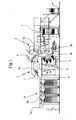
- Figure 1 illustrates the general arrangement of the units constituting an intaglio printing machine.
- a sheet feeder unit 1 a printing unit 2, including an impression cylinder 2a, a plate cylinder 2b and a collecting cylinder 2c.
- an inking carriage 3 suspended under a frame 4.
- the sheets are fed from the sheet feeder unit 1 to the impression cylinder 2a of the printing unit 2 which carries the sheets one after the other to the printing nip between the impression cylinder 2a and the plate cylinder 2b where printing of the sheets occurs.
- the impression cylinder 2a hands over the printed sheets to a sheet transporting system consisting in this example of an endless chain conveyor system with endless chains and gripper bars, generally designated by 5, as such known in the art.
- the transporting system 5 carries the sheets above the frame 4, in front of an inspection unit 6 and a drying unit 7, and down to the delivery unit 8.
- the sheets are transferred from the impression cylinder 2a to the transporting system 5, and transported by the same in front of the inspection unit 6 and the drying unit 7 with the freshly printed side facing down. Thereafter, the sheets run above the delivery unit 8, still with the freshly printed side facing down, are reversed at the outermost left position of the machine and delivered to the appropriate delivery pile with the freshly printed side facing up.
- Gripper release devices are disposed in each delivery module so as to selectively deliver a sheet in the desired delivery pile, such gripper release devices are described for example in Applicant's patent application PCT/IB2005/001113, incorporated herein by reference.
- the return path of the endless chain conveyor system 5, from the delivery unit 8 back to the printing unit 2, is illustrated in figure 1 by dash-dot line 9.
- a top module 5a is located above the frame 4 of the inking carriage 3, providing an interior space accommodating the inspection unit 6 and the drying device 7.
- a delivery module 5b is mounted above each delivery pile, and a reversal module 5c is mounted laterally at the free end of the outermost delivery module.
- Figure 1 shows three delivery modules, one above each pile, whereas figure 2 shows only one delivery module for the sake of simplicity.
- the module 5a comprises two side frames 10a, 10b, fitting with the frame 4 of the inking carriage 3.
- the delivery modules 5b and the reversal module 5c each comprise two side frames 11a, 11b, respectively 12a, 12b, fitting together.
- Between the side frames of each module is mounted at least one transverse row 13, 14, 15, of rod holders 17, the structure of which is illustrated in greater detail in figure 3.
- Similar rows of rod holders are distributed at regular intervals along the sheet transport path so as to provide adequate support for a plurality of longitudinal guidance rods 16, 26 distributed transversely to the direction of displacement of the sheets.
- eight guidance rods are mounted in such a way and held at regular intervals by the rows 13, 14, 15 of rod holders 17.
- the guidance rods 16 of the top module 5a and of the delivery module 5b are generally straight or locally slightly curved, whereas the guidance rods 26 of the reversal module 5c are shaped as curved elements.
- the guidance rods 16, 26 can be mostly continuous or be broken down into several guiding rod segments mounted one behind the other between the successive rows of rod holders.
- endless chains and gripper bars of the endless chain conveyor system are not illustrated in the drawings. It will however be understood that the endless chains are located between the side frames 10a, 10b, 11a, 11b, 12a, 12b and that the gripper bars move immediately below the guiding rods 16, 26 which are accordingly located immediately above the upper side of the transported sheets.
- the top module 5a and the delivery modules 5b are provided with transverse blowing pipes 24 for blowing air under pressure against the transported sheets.
- the reversal module 5c is provided with a curved blowing surface 25 with perforations for similarly blowing air under pressure against the transported sheets.
- These blowing means 24, 25 are disposed under the path of the gripper bars so as to blow air against the under side of the transported sheets.
- the perforations of the transverse perforated pipes 24 and of the curved blowing surface 25, are directed perpendicular to the transport path, in direction of the guidance rods 16, 26.
- the air blown by the blowing pipes 24 and the blowing surface 25 presses the sheets during transport against the guidance rods 16 and 26. It will be appreciated that the blown air not only maintains the sheets along the guidance rods but also contributes to improving the drying of the sheets.
- the sheets might be drawn against the guidance rods 16, 26 by means of air depression caused by suction means arranged on the same side of the sheets as the guidance rods 16, 26.
- suction means are well-known in the art and do not need to be described in detail. Blowing means and suction means could even be combined if necessary.
- each rod holder 17 comprises a holding portion 18 for holding a corresponding portion of a guidance rod 16, 26 or, alternatively, for holding end to end the two end portions of two successive guidance rod segments.
- the body 19 of each rod holder 17 is provided with a through hole, by means of which the rod holder 17 is mounted slidingly on a guiding crossbar 20, the latter being mounted transversely between the side frames.
- the rod holder 17 further includes an electric motor 21 and a gearbox 22, the latter engaging a threaded shaft member 23 mounted between the side frames, parallel to the guiding crossbar 20. Activation of the motor 21 causes a transverse translation of the corresponding rod holder 17 through the interaction of the gearbox 22 and the threaded shaft member 23.
- Other mechanisms for translating the rod holders 17 transversely to the direction of displacement of the sheets might be envisaged, such as driving the rod holders 17 on an transverse rack-rail member.
- each rod holder 17 be connected to a central control unit so as to be able to actuate simultaneously all the rod holders 17 which are coupled to a common line of guidance rods 16, 26 and ensure that the alignment with the sheet transporting direction is maintained. It might however be advantageous to be able to adjust the position of each rod holder 17 independently of the others, in order to provide fine adjustment the alignment of the guidance rods 16, 26.
- Control of the individual rod holders 17 can be implemented by a common central processing unit (CPU), not shown operatively coupled to the motors 22.
- This CPU can control the transverse positions of all rod holders 17, and can advantageously be provided with means for storing a predetermined set of position settings for usual sheet format or sizes and print layouts. The adequacy of these settings can be controlled visually at the beginning of each run.
Abstract
There is described a sheet transporting system for carrying sheets on a transport path in a sheet-fed printing and/or processing machine, comprising a gripper system driving said sheets along said transport path and a plurality of parallel sheet guidance rods (16, 26), arranged longitudinally along said transport path and guiding said sheets on said transport path. The guidance rods are mounted on transversely movable rod holders (17) which are coupled to driving means (21, 22, 23) adapted to adjust the transverse positions of the guidance rods (16, 26).
Description
- The present invention concerns a sheet transporting system for carrying sheets on a transport path in a sheet-fed printing and/or processing machine, comprising a gripper system driving said sheets along said transport path and a plurality of parallel sheet guidance rods, arranged longitudinally along said transport path and guiding said sheets on said transport path.
- Depending on the overall machine configuration, a sheet-fed printing and/or processing machine commonly includes a printing and/or processing unit for printing and/or processing the sheets and, optionally, one or more additional processing modules (such as an inspection module, a drying device, a laser marking or perforating device, or any other processing device for processing the sheets) disposed in the sheet delivery path between the printing and/or processing unit and a sheet delivery unit. Known delivery units usually include a plurality of delivery piles where the sheets are delivered. Typically, a sheet-fed printing and/or processing machine with inspection capability is provided with at least three delivery piles, one delivery pile for sheets having a defect, and two delivery piles, filled alternately, for the sheets which are considered meeting the quality requirements. Such a delivery unit is for instance disclosed in Applicant's patent application
PCT/IB2005/001113 - The transport path of the endless chain gripper system may vary depending on the overall machine configuration, but at least one portion of the path goes from the printing or processing unit through the delivery modules and defines a so called "delivery path", whereas the remaining part of the transport path, which returns from the last one of the delivery modules to the printing or processing unit, defines a so called "return path".
- Whereas the leading edge of each sheet is held by the grippers of a gripper bar, a substantial portion of the remaining surface of the sheet have to be supported by guide means like guide plates or guide drums in order to prevent soiling of the sheets, this being especially critical when the sheets are transported to the delivery unit with a freshly-printed side of the sheets facing downward as this side shall preferably not come in contact with any obstacle under the effect of gravity. Moreover, even portions of the opposite side of the sheets may still be somewhat wet, due to a previous printing or marking step on the said opposite side. This is particularly the case with intaglio-printed sheets where the deposited ink is relatively thick and can remain wet for a certain period of time. Therefore, it is advisable to support only some selected areas of the opposite side of the sheets, by means of longitudinally arranged straight guidance rods or the like, instead of plates, on straight portions of the transport path, and by means of a number of parallel curved guidance rods, discs or the like, instead of drums, at locations where sheets shall undergo a turn or be reversed.
- In particular, if the sheets bear prints arranged in rows and columns, as this is common in the art of printing security papers, these guide means can advantageously be arranged so as to come in contact only with the margins between the prints in order to avoid soiling of the prints themselves.
- However, if the format of the sheets or the layout of the individual prints on the sheets changes widthwise, the positions of these guide rods or guide discs must be changed. This is a tedious manual operation, necessitating a generally long machine stop.
- It is therefore an aim of the invention to improve the sheet transporting systems of the prior art, especially the sheet transporting systems of the type comprising longitudinal guidance rods or members for supporting the sheets lengthwise.
- It is another aim of the present invention to provide a transporting system, which may be readily adjusted to various sheet formats and print layouts.
- It is another aim of the present invention to provide a transporting system that can be customised and adapted to several different machines.
- It is a further aim of the present invention to provide a transporting system that is modular.
- Thus, an object of the invention is a sheet transporting system of the type defined above, wherein the sheet guidance rods are mounted on transversely movable rod holders, and wherein these rod holders are coupled to driving means adapted to adjust the transverse positions of the guidance rods.
- The term "longitudinal" as used herein and in the claims has the usual meaning of parallel to the sheet displacement direction; the term "transverse" as used herein and in the claims has the usual meaning of perpendicular to the sheet displacement direction and parallel to the sheet plane.
- Preferably, each rod holder is coupled to a driving means adapted to adjust the transverse position of the rod holder (and thereby of each guidance rod) independently of the transverse positions of the other rod holders.
- In a preferred embodiment, each rod holder is slidingly mounted on a crossbar and is coupled to a motor and to a gearbox, the gearbox engaging a transverse threaded shaft member.
- In a preferred embodiment, the driving means of the rod holders are connected to a common control unit for controlling the transverse positions of the guidance rods.
- In a preferred embodiment, each guidance rod is held between at least a corresponding pair of rod holders, spaced apart longitudinally along the sheet transport path, transverse displacement of each guidance rod being controlled by simultaneous displacement of the said corresponding pair of rod holders.
- The sheets may additionally be drawn against the guidance rods by means of air depression caused by suction means arranged on the same side of the sheets as the guidance rods.
- Alternatively, the sheets may be pressed against the guidance rods by means of air overpressure caused by blowing means facing the sheets and located on the side of the sheets opposite to the guidance rods. An advantage of this arrangement resides in that the blown air also contributes to improving the drying of freshly-printed sheets.
- In a preferred embodiment, the blowing means include perforated blowing pipes arranged transversely to the transport path.
- Preferably, the transporting system comprises a number of aggregate modules arranged in line along the sheet transport path, each module comprising at least a transverse row of said rod holders.
- The sheet transporting system may in particular be used for transporting sheets from a printing unit to a delivery unit of a printing machine, by adopting a configuration wherein the sheet transporting system comprises at least one aggregate top transport module, where the sheets are transported with a freshly printed side facing downward, the other side of the sheets facing the guidance rods. In this case, the sheet transporting system further comprises a reversal module for reversing the sheets, where the sheets are guided by guidance rods shaped as curved elements, the reversal module delivering the sheets to the delivery unit with the freshly printed side facing up.
- Particulars and advantages of the invention will be best understood with the following description of an exemplary embodiment and the accompanying drawings, in which:
- Figure 1 is a general side view of an intaglio printing machine;
- Figure 2 is a partial perspective view of an embodiment of a sheet transporting system according to the invention;
- Figure 3 is an enlarged perspective view of a transverse row of rod holders of the embodiment of figure 2.
- Figure 1 illustrates the general arrangement of the units constituting an intaglio printing machine. Those skilled in the art will easily recognise, from right to left, a
sheet feeder unit 1, aprinting unit 2, including animpression cylinder 2a, aplate cylinder 2b and a collectingcylinder 2c. At the left of the collectingcylinder 2c is an inkingcarriage 3, suspended under aframe 4. The sheets are fed from thesheet feeder unit 1 to theimpression cylinder 2a of theprinting unit 2 which carries the sheets one after the other to the printing nip between theimpression cylinder 2a and theplate cylinder 2b where printing of the sheets occurs. After printing of the sheets, theimpression cylinder 2a hands over the printed sheets to a sheet transporting system consisting in this example of an endless chain conveyor system with endless chains and gripper bars, generally designated by 5, as such known in the art. Thetransporting system 5 carries the sheets above theframe 4, in front of an inspection unit 6 and adrying unit 7, and down to the delivery unit 8. - In the configuration of the machine illustrated in figure 1, the sheets are transferred from the
impression cylinder 2a to thetransporting system 5, and transported by the same in front of the inspection unit 6 and thedrying unit 7 with the freshly printed side facing down. Thereafter, the sheets run above the delivery unit 8, still with the freshly printed side facing down, are reversed at the outermost left position of the machine and delivered to the appropriate delivery pile with the freshly printed side facing up. Gripper release devices are disposed in each delivery module so as to selectively deliver a sheet in the desired delivery pile, such gripper release devices are described for example in Applicant's patent application PCT/IB2005/001113, incorporated herein by reference. The return path of the endlesschain conveyor system 5, from the delivery unit 8 back to theprinting unit 2, is illustrated in figure 1 by dash-dot line 9. - As may be seen from figures 1 and 2, it is advantageous to construct the frame and the mechanical parts of the
transporting system 5 as separate modules. In the illustrated configuration, atop module 5a is located above theframe 4 of the inkingcarriage 3, providing an interior space accommodating the inspection unit 6 and thedrying device 7. Adelivery module 5b is mounted above each delivery pile, and areversal module 5c is mounted laterally at the free end of the outermost delivery module. Figure 1 shows three delivery modules, one above each pile, whereas figure 2 shows only one delivery module for the sake of simplicity. - As may be seen in figure 2, the
module 5a comprises twoside frames frame 4 of the inkingcarriage 3. Thedelivery modules 5b and thereversal module 5c each comprise twoside frames 11a, 11b, respectively 12a, 12b, fitting together. Between the side frames of each module is mounted at least onetransverse row longitudinal guidance rods 16, 26 distributed transversely to the direction of displacement of the sheets. In the illustrated configuration, eight guidance rods are mounted in such a way and held at regular intervals by therows top module 5a and of thedelivery module 5b, are generally straight or locally slightly curved, whereas the guidance rods 26 of thereversal module 5c are shaped as curved elements. Theguidance rods 16, 26 can be mostly continuous or be broken down into several guiding rod segments mounted one behind the other between the successive rows of rod holders. - The endless chains and gripper bars of the endless chain conveyor system are not illustrated in the drawings. It will however be understood that the endless chains are located between the
side frames rods 16, 26 which are accordingly located immediately above the upper side of the transported sheets. - The
top module 5a and thedelivery modules 5b, are provided with transverse blowingpipes 24 for blowing air under pressure against the transported sheets. Thereversal module 5c is provided with a curved blowing surface 25 with perforations for similarly blowing air under pressure against the transported sheets. These blowing means 24, 25 are disposed under the path of the gripper bars so as to blow air against the under side of the transported sheets. As may be best seen in figure 2, the perforations of the transverseperforated pipes 24 and of the curved blowing surface 25, are directed perpendicular to the transport path, in direction of theguidance rods 16, 26. Since the sheets are transported between the guidance rods and the blowing means 24, 25, the air blown by the blowingpipes 24 and the blowing surface 25 presses the sheets during transport against theguidance rods 16 and 26. It will be appreciated that the blown air not only maintains the sheets along the guidance rods but also contributes to improving the drying of the sheets. - Alternatively, rather than blowing air against the sheets, the sheets might be drawn against the
guidance rods 16, 26 by means of air depression caused by suction means arranged on the same side of the sheets as theguidance rods 16, 26. Such suction means are well-known in the art and do not need to be described in detail. Blowing means and suction means could even be combined if necessary. - As shown in Figure 3, each rod holder 17 comprises a holding
portion 18 for holding a corresponding portion of aguidance rod 16, 26 or, alternatively, for holding end to end the two end portions of two successive guidance rod segments. Thebody 19 of each rod holder 17 is provided with a through hole, by means of which the rod holder 17 is mounted slidingly on a guidingcrossbar 20, the latter being mounted transversely between the side frames. The rod holder 17 further includes anelectric motor 21 and agearbox 22, the latter engaging a threadedshaft member 23 mounted between the side frames, parallel to the guidingcrossbar 20. Activation of themotor 21 causes a transverse translation of the corresponding rod holder 17 through the interaction of thegearbox 22 and the threadedshaft member 23. Other mechanisms for translating the rod holders 17 transversely to the direction of displacement of the sheets might be envisaged, such as driving the rod holders 17 on an transverse rack-rail member. - Those skilled in the art will appreciate that transverse displacement of a given longitudinal line of
guidance rods 16, 26 requires simultaneous actuation of the corresponding rod holders 17 for that given longitudinal line, so that the parallelism with the other longitudinal lines of guidance rods is retained. The longitudinal alignment (or parallelism) of theguidance rods 16, 26 can be adjusted by playing with the transverse position of each rod holder 17 along a given longitudinal line. It is thus preferred that each rod holder 17 be connected to a central control unit so as to be able to actuate simultaneously all the rod holders 17 which are coupled to a common line ofguidance rods 16, 26 and ensure that the alignment with the sheet transporting direction is maintained. It might however be advantageous to be able to adjust the position of each rod holder 17 independently of the others, in order to provide fine adjustment the alignment of theguidance rods 16, 26. - Control of the individual rod holders 17 can be implemented by a common central processing unit (CPU), not shown operatively coupled to the
motors 22. This CPU can control the transverse positions of all rod holders 17, and can advantageously be provided with means for storing a predetermined set of position settings for usual sheet format or sizes and print layouts. The adequacy of these settings can be controlled visually at the beginning of each run. - It will be appreciated that various modifications and/or improvements can be made to the above described embodiments without departing from the scope of the annexed claims. For instance, while the above embodiments of the sheet transporting system are described in the context of an intaglio printing machine, such sheet transporting system might be used in other types of printing and/or processing machines.
Claims (10)
- A sheet transporting system for carrying sheets on a transport path in a sheet-fed printing and/or processing machine, comprising a gripper system driving said sheets along said transport path and a plurality of parallel sheet guidance rods (16, 26), arranged longitudinally along said transport path and guiding said sheets on said transport path,
wherein said sheet guidance rods (16, 26) are mounted on transversely movable rod holders (17) which are coupled to driving means (21, 22, 23) adapted to adjust the transverse positions of said guidance rods (16, 26). - A sheet transporting system as claimed in claim 1, wherein each rod holder (17) is coupled to a driving means (21, 22, 23) adapted to adjust the transverse position of the rod holder independently of the transverse positions of the other rod holders (17).
- A sheet transporting system as claimed in claim 1 or 2, wherein each rod holder (17) is slidingly mounted on a crossbar (20) and is coupled to a motor (21) and to a gearbox (22), said gearbox (22) engaging a transverse threaded shaft member (23).
- A sheet transporting system as claimed in any one of claims 1 to 3, wherein said driving means (21, 22, 23) of the rod holders (17) are connected to a common control unit for controlling the transverse positions of the guidance rods (16, 26).
- A sheet transporting system as claimed in any one of the preceding claims, wherein each guidance rod (16, 26) is held between at least a corresponding pair of rod holders (17), spaced-apart longitudinally along the sheet transport path, transverse displacement of each guidance rod (16, 26) being controlled by simultaneous displacement of the said corresponding pair of rod holders (17).
- A sheet transporting system as claimed in any one of the preceding claims, wherein the sheets are drawn against the guidance rods (16, 26) by means of air depression caused by suction means arranged on the same side of the sheets as the guidance rods (16, 26).
- A sheet transporting system as claimed in any one of claims 1 to 5, wherein the sheets are pressed against the guidance rods (16, 26) by means of air overpressure caused by blowing means (24, 25) facing the sheets and located on the side of the sheets opposite to said guidance rods (16, 26).
- A sheet transporting system as claimed in claim 7, wherein said blowing means (24, 25) include perforated blowing tubes (24) arranged parallel and transversely to the transport path
- A sheet transporting system as claimed in any one of the preceding claims, wherein said transporting system comprises a number of aggregate modules (5a, 5b, 5c) arranged in line along the sheet transport path, each module (5a, 5b, 5c) comprising at least a transverse row (13, 14, 15) of said rod holders (17).
- A sheet transporting system as claimed in claim 9, for transporting sheets from a printing unit (2) to a delivery unit (8), comprising at least one aggregate top transport module (5a; 5b), where the sheets are transported with a freshly printed side facing downward, while the other side of the sheets is guided onto guidance rods (16), said sheet transporting system further comprising a reversal module (5c), where the sheets are guided by guidance rods (26) shaped as curved elements, said reversal module (5c) delivering said sheets to the delivery unit (8) with the freshly printed side facing up.
Priority Applications (1)
| Application Number | Priority Date | Filing Date | Title |
|---|---|---|---|
| EP05022658A EP1777184A1 (en) | 2005-10-18 | 2005-10-18 | Sheet transporting system |
Applications Claiming Priority (1)
| Application Number | Priority Date | Filing Date | Title |
|---|---|---|---|
| EP05022658A EP1777184A1 (en) | 2005-10-18 | 2005-10-18 | Sheet transporting system |
Publications (1)
| Publication Number | Publication Date |
|---|---|
| EP1777184A1 true EP1777184A1 (en) | 2007-04-25 |
Family
ID=35998513
Family Applications (1)
| Application Number | Title | Priority Date | Filing Date |
|---|---|---|---|
| EP05022658A Withdrawn EP1777184A1 (en) | 2005-10-18 | 2005-10-18 | Sheet transporting system |
Country Status (1)
| Country | Link |
|---|---|
| EP (1) | EP1777184A1 (en) |
Cited By (1)
| Publication number | Priority date | Publication date | Assignee | Title |
|---|---|---|---|---|
| EP2138437A1 (en) | 2008-06-27 | 2009-12-30 | Kba-Giori S.A. | Inspection system for inspecting the quality of printed sheets |
Citations (11)
| Publication number | Priority date | Publication date | Assignee | Title |
|---|---|---|---|---|
| GB1006394A (en) * | 1962-08-29 | 1965-09-29 | Johannisberg Gmbh Maschf | Improvements relating to a method of and apparatus for turning and depositing printed sheets in printing machines |
| DD125394A1 (en) * | 1976-02-27 | 1977-04-20 | ||
| US4225129A (en) * | 1978-01-25 | 1980-09-30 | Veb Polygraph Leipzig Kombinat Fuer Polygraphische Maschinen Und Ausruestungen | Sheet guidance arrangement in printing-machine outfeed units |
| US4572073A (en) * | 1983-11-25 | 1986-02-25 | M.A.N.-Roland Druckmaschinen Aktiengesellschaft | Sheet guide arrangement in sheet-fed machines |
| DE3533857A1 (en) * | 1984-10-05 | 1986-04-10 | VEB Kombinat Polygraph "Werner Lamberz" Leipzig, DDR 7050 Leipzig | Device on trolleys of sheet conveying devices in printing machines |
| DE3736168A1 (en) * | 1987-02-27 | 1988-09-08 | Polygraph Leipzig | Adjusting drive for guide devices |
| US5228391A (en) * | 1990-12-31 | 1993-07-20 | Howard W. DeMoore | Vacuum transfer apparatus for rotary sheet-fed printing presses |
| US5259309A (en) * | 1992-01-31 | 1993-11-09 | Koenig & Bauer Aktiengesellschaft | Adjustable sheet guide assembly |
| EP1094023A2 (en) * | 1999-10-20 | 2001-04-25 | Heidelberger Druckmaschinen Aktiengesellschaft | Sheet guiding device for machines processing printed sheets |
| EP1489031A2 (en) * | 2003-06-19 | 2004-12-22 | Komori Corporation | Guide device for sheet |
| DE102004031752A1 (en) * | 2003-07-24 | 2005-02-17 | Heidelberger Druckmaschinen Ag | Device for feed of sheets in printing machine has guide element in form of long coil extension spring with coils wound from round wire, whereby several coil springs are provided in parallel arrangement with ends fastened on common holder |
-
2005
- 2005-10-18 EP EP05022658A patent/EP1777184A1/en not_active Withdrawn
Patent Citations (11)
| Publication number | Priority date | Publication date | Assignee | Title |
|---|---|---|---|---|
| GB1006394A (en) * | 1962-08-29 | 1965-09-29 | Johannisberg Gmbh Maschf | Improvements relating to a method of and apparatus for turning and depositing printed sheets in printing machines |
| DD125394A1 (en) * | 1976-02-27 | 1977-04-20 | ||
| US4225129A (en) * | 1978-01-25 | 1980-09-30 | Veb Polygraph Leipzig Kombinat Fuer Polygraphische Maschinen Und Ausruestungen | Sheet guidance arrangement in printing-machine outfeed units |
| US4572073A (en) * | 1983-11-25 | 1986-02-25 | M.A.N.-Roland Druckmaschinen Aktiengesellschaft | Sheet guide arrangement in sheet-fed machines |
| DE3533857A1 (en) * | 1984-10-05 | 1986-04-10 | VEB Kombinat Polygraph "Werner Lamberz" Leipzig, DDR 7050 Leipzig | Device on trolleys of sheet conveying devices in printing machines |
| DE3736168A1 (en) * | 1987-02-27 | 1988-09-08 | Polygraph Leipzig | Adjusting drive for guide devices |
| US5228391A (en) * | 1990-12-31 | 1993-07-20 | Howard W. DeMoore | Vacuum transfer apparatus for rotary sheet-fed printing presses |
| US5259309A (en) * | 1992-01-31 | 1993-11-09 | Koenig & Bauer Aktiengesellschaft | Adjustable sheet guide assembly |
| EP1094023A2 (en) * | 1999-10-20 | 2001-04-25 | Heidelberger Druckmaschinen Aktiengesellschaft | Sheet guiding device for machines processing printed sheets |
| EP1489031A2 (en) * | 2003-06-19 | 2004-12-22 | Komori Corporation | Guide device for sheet |
| DE102004031752A1 (en) * | 2003-07-24 | 2005-02-17 | Heidelberger Druckmaschinen Ag | Device for feed of sheets in printing machine has guide element in form of long coil extension spring with coils wound from round wire, whereby several coil springs are provided in parallel arrangement with ends fastened on common holder |
Cited By (4)
| Publication number | Priority date | Publication date | Assignee | Title |
|---|---|---|---|---|
| EP2138437A1 (en) | 2008-06-27 | 2009-12-30 | Kba-Giori S.A. | Inspection system for inspecting the quality of printed sheets |
| EP2383213A1 (en) | 2008-06-27 | 2011-11-02 | Kba-Notasys Sa | Inspection system for inspecting the quality of printed sheets |
| US9156245B2 (en) | 2008-06-27 | 2015-10-13 | Kba-Notasys Sa | Inspection system for inspecting the quality of printed sheets |
| US9387667B2 (en) | 2008-06-27 | 2016-07-12 | Kba-Notasys Sa | Inspection system for inspecting the quality of printed sheets |
Similar Documents
| Publication | Publication Date | Title |
|---|---|---|
| JP3025477B2 (en) | Sheet guide for printing press | |
| JP5837030B2 (en) | An intaglio printing press system for intaglio printing on the front-back side of a sheet of paper to produce banknotes and similar securities | |
| EP1747904B1 (en) | Printing machine with laser perforating unit | |
| JP4885840B2 (en) | Printing method and printing machine | |
| JPH11320832A (en) | Feeding apparatus provided at sheet-fed rotary printer | |
| JP3759177B2 (en) | Chain conveyor for sheet-fed printing machines | |
| JPH02188364A (en) | Paper conveying apparatus | |
| JP2004522669A (en) | Method for separating a single sheet from a stack of sheets as print media | |
| JPH1076634A (en) | Pneumatic sheet-guide apparatus provided in printing machine | |
| EP1088657B1 (en) | Printing machine | |
| JP2004314605A (en) | Device for transferring sheet through printing machine | |
| JP5355340B2 (en) | Printing machine that prints sheets on both sides | |
| EP1777184A1 (en) | Sheet transporting system | |
| US6527268B2 (en) | Method and device for contact-free guidance of sheets | |
| EP1400353A1 (en) | Intaglio printing machine | |
| US6557468B2 (en) | Delivery for a sheet processing machine, particularly for a sheet-fed printing machine | |
| ES2205709T5 (en) | SHEET RECEPTION DEVICE IN A ROTATING MACHINE TO PRINT SHEETS. | |
| JP3920824B2 (en) | Machine for processing flat substrates with an auxiliary pile support | |
| EP1088654A1 (en) | Printing machine | |
| JP2000503963A (en) | Equipment to supply web paper to folding equipment | |
| CN113544070B (en) | Conveyor for sheet-like substrates | |
| EP1740489B1 (en) | Delivery unit for sheet-fed printing or processing machines | |
| JP2015067446A (en) | Device and method for ejecting sheet | |
| CN105460647B (en) | Method and apparatus for page to be discharged | |
| JP6468685B2 (en) | Sheet-fed printing machine |
Legal Events
| Date | Code | Title | Description |
|---|---|---|---|
| PUAI | Public reference made under article 153(3) epc to a published international application that has entered the european phase |
Free format text: ORIGINAL CODE: 0009012 |
|
| AK | Designated contracting states |
Kind code of ref document: A1 Designated state(s): AT BE BG CH CY CZ DE DK EE ES FI FR GB GR HU IE IS IT LI LT LU LV MC NL PL PT RO SE SI SK TR |
|
| AX | Request for extension of the european patent |
Extension state: AL BA HR MK YU |
|
| AKX | Designation fees paid | ||
| REG | Reference to a national code |
Ref country code: DE Ref legal event code: 8566 |
|
| STAA | Information on the status of an ep patent application or granted ep patent |
Free format text: STATUS: THE APPLICATION IS DEEMED TO BE WITHDRAWN |
|
| 18D | Application deemed to be withdrawn |
Effective date: 20071026 |