EP1777153A2 - Marine vessel and marine drive combination - Google Patents
Marine vessel and marine drive combination Download PDFInfo
- Publication number
- EP1777153A2 EP1777153A2 EP06020075A EP06020075A EP1777153A2 EP 1777153 A2 EP1777153 A2 EP 1777153A2 EP 06020075 A EP06020075 A EP 06020075A EP 06020075 A EP06020075 A EP 06020075A EP 1777153 A2 EP1777153 A2 EP 1777153A2
- Authority
- EP
- European Patent Office
- Prior art keywords
- starboard
- port
- marine
- propulsion device
- tunnel
- Prior art date
- Legal status (The legal status is an assumption and is not a legal conclusion. Google has not performed a legal analysis and makes no representation as to the accuracy of the status listed.)
- Granted
Links
Images





Classifications
-
- B—PERFORMING OPERATIONS; TRANSPORTING
- B63—SHIPS OR OTHER WATERBORNE VESSELS; RELATED EQUIPMENT
- B63B—SHIPS OR OTHER WATERBORNE VESSELS; EQUIPMENT FOR SHIPPING
- B63B39/00—Equipment to decrease pitch, roll, or like unwanted vessel movements; Apparatus for indicating vessel attitude
- B63B39/06—Equipment to decrease pitch, roll, or like unwanted vessel movements; Apparatus for indicating vessel attitude to decrease vessel movements by using foils acting on ambient water
- B63B39/061—Equipment to decrease pitch, roll, or like unwanted vessel movements; Apparatus for indicating vessel attitude to decrease vessel movements by using foils acting on ambient water by using trimflaps, i.e. flaps mounted on the rear of a boat, e.g. speed boat
-
- B—PERFORMING OPERATIONS; TRANSPORTING
- B63—SHIPS OR OTHER WATERBORNE VESSELS; RELATED EQUIPMENT
- B63H—MARINE PROPULSION OR STEERING
- B63H25/00—Steering; Slowing-down otherwise than by use of propulsive elements; Dynamic anchoring, i.e. positioning vessels by means of main or auxiliary propulsive elements
- B63H25/42—Steering or dynamic anchoring by propulsive elements; Steering or dynamic anchoring by propellers used therefor only; Steering or dynamic anchoring by rudders carrying propellers
-
- B—PERFORMING OPERATIONS; TRANSPORTING
- B63—SHIPS OR OTHER WATERBORNE VESSELS; RELATED EQUIPMENT
- B63H—MARINE PROPULSION OR STEERING
- B63H5/00—Arrangements on vessels of propulsion elements directly acting on water
- B63H5/07—Arrangements on vessels of propulsion elements directly acting on water of propellers
- B63H5/08—Arrangements on vessels of propulsion elements directly acting on water of propellers of more than one propeller
- B63H5/10—Arrangements on vessels of propulsion elements directly acting on water of propellers of more than one propeller of coaxial type, e.g. of counter-rotative type
-
- B—PERFORMING OPERATIONS; TRANSPORTING
- B63—SHIPS OR OTHER WATERBORNE VESSELS; RELATED EQUIPMENT
- B63H—MARINE PROPULSION OR STEERING
- B63H5/00—Arrangements on vessels of propulsion elements directly acting on water
- B63H5/07—Arrangements on vessels of propulsion elements directly acting on water of propellers
- B63H5/125—Arrangements on vessels of propulsion elements directly acting on water of propellers movably mounted with respect to hull, e.g. adjustable in direction, e.g. podded azimuthing thrusters
-
- B—PERFORMING OPERATIONS; TRANSPORTING
- B63—SHIPS OR OTHER WATERBORNE VESSELS; RELATED EQUIPMENT
- B63H—MARINE PROPULSION OR STEERING
- B63H5/00—Arrangements on vessels of propulsion elements directly acting on water
- B63H5/07—Arrangements on vessels of propulsion elements directly acting on water of propellers
- B63H5/16—Arrangements on vessels of propulsion elements directly acting on water of propellers characterised by being mounted in recesses; with stationary water-guiding elements; Means to prevent fouling of the propeller, e.g. guards, cages or screens
-
- B—PERFORMING OPERATIONS; TRANSPORTING
- B63—SHIPS OR OTHER WATERBORNE VESSELS; RELATED EQUIPMENT
- B63H—MARINE PROPULSION OR STEERING
- B63H5/00—Arrangements on vessels of propulsion elements directly acting on water
- B63H5/07—Arrangements on vessels of propulsion elements directly acting on water of propellers
- B63H5/125—Arrangements on vessels of propulsion elements directly acting on water of propellers movably mounted with respect to hull, e.g. adjustable in direction, e.g. podded azimuthing thrusters
- B63H2005/1254—Podded azimuthing thrusters, i.e. podded thruster units arranged inboard for rotation about vertical axis
- B63H2005/1256—Podded azimuthing thrusters, i.e. podded thruster units arranged inboard for rotation about vertical axis with mechanical power transmission to propellers
Definitions
- the present invention relates to a marine drive for propelling a marine vessel with the features of the introductory part of claim 1 as well as a marine vessel and drive combination with the features of the introductory part of claim 3.
- Marine drives as well as marine vessel and drive combinations are known in the prior art (see e.g. US-A-5,108,325 ).
- the marine drive of this marine vessel includes a trim tab for contact by the water for adjusting vessel attitude and/or altering thrust vectors, or otherwise affecting hydrodynamic operation of the vessel.
- the trim tab is fixedly positioned on the marine drive and trimming is done by pivoting the complete marine drive up and down about a horizontal axis.
- the object of the present invention is to provide a marine drive and marine vessel and drive combination which is improved as far as the hydrodynamic operation of the vessel is concerned.
- This object is met by a marine drive comprising the features of claim 1 and by a marine vessel and drive combination comprising the features of claim 3.
- Preferable modifications and improvements of the invention are the subject of the dependent claims.
- the invention is described with reference to the drawings which show, by way of example only, a preferred embodiment of the invention.
- Fig. 1 is a perspective view of a marine vessel and drive combination in accordance with the invention.
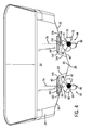
- Fig. 2 is a bottom elevation view of the combination of Fig. 1.
- Fig. 3 is a side elevation view of the combination of Fig. 1.
- Fig. 4 is a rear or aft elevation view of the combination of Fig. 1.
- Fig. 5 is an enlarged view of a portion of Fig. 3.
- Fig. 5A is like a portion of Fig. 5 and shows an alternate embodiment.
- Fig. 5B is an enlarged rear elevation view of a portion of Fig. 5.
- Fig. 6 is an enlarged view of a portion of Fig. 2.
- Fig. 7 is like Fig. 6 and shows a different steering orientation.
- Fig. 8 is like Fig. 6 and shows another different steering orientation.
- Fig. 9 is an enlarged view of a portion of Fig. 1.
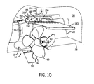
- Fig. 10 is like Fig. 9 and shows a further operational embodiment.
- Fig. 11 is a side view showing the arrangement of an engine and marine propulsion device used in conjunction with the present invention.
- Marine vessel 22 includes a hull 24 having a longitudinally extending keel 26 having a lower reach 28.
- the hull has port and starboard lower hull surfaces 30 and 32, respectively, extending upwardly and laterally distally oppositely from keel 26 in V-shaped relation, Fig. 4.
- Hull 24 extends forwardly from a stem 34 to a bow 36.
- a port tunnel 38 is formed in port lower hull surface 30.
- Port tunnel 38 has a top 40, Fig. 4, spaced above an open bottom 42 at port lower hull surface 30.
- Port tunnel 38 opens aft at stem 34 and extends forwardly therefrom and has a closed forward end 44 aft of bow 36.
- a starboard tunnel 46 is formed in starboard lower hull surface 32.
- Starboard tunnel 46 has a top 48 spaced above an open bottom 50 at starboard lower hull surface 32.
- Starboard tunnel 46 opens aft at stem 34 and extends forwardly therefrom and has a closed forward end 52 aft of bow 36.
- a port marine propulsion device 54 includes a port driveshaft housing 56 extending downwardly in port tunnel 38 to a port lower gear case 58, e.g. including a torpedo-shaped housing as is known, supporting at least one port propeller shaft 60 driving at least one water-engaging propulsor such as port propeller 62, and preferably a pair of propeller shafts driving counter-rotating propellers 62, 63, as is known, for example U.S. Patents 5,108,325 , 5,230,644 , 5,366,398 , 5,415,576 , 5,425,663 , all incorporated herein by reference.
- Starboard marine propulsion device 64 is comparable and includes a starboard driveshaft housing 66 extending downwardly in starboard tunnel 46 to starboard lower gear case 68, e.g. provided by the noted torpedo-shaped housing, supporting at least one starboard propeller shaft 70 driving at least one starboard propeller 72, and preferably a pair of counter-rotating starboard propellers 72, 73, as above.
- the port and starboard marine propulsion devices 54 and 64 are steerable about respective port and starboard vertical steering axes 74 and 76, comparably as shown in commonly owned co-pending EPC-applications 06.......... related to a "Method for Maneuvering a Marine Vessel " and 06..........
- Port steering axis 74 extends through the top 40 of port tunnel 38.
- Starboard steering axis 76 extends through the top 48 of starboard tunnel 46.
- Tops 40 and 48 of port and starboard tunnels 38 and 46 are at a given vertical elevation, Fig. 4, spaced vertically above lower reach 28 of keel 26 to provide port and starboard tunnels 38 and 46 with a given vertical height receiving port and starboard marine propulsion devices 54 and 64 and raising same relative to keel 26, such that keel 26 at least partially protects port and starboard marine propulsion devices 54 and 64 from striking underwater objects, including grounding, during forward propulsion of the vessel.
- At least a portion of port driveshaft housing 56 is in port tunnel 38 and above open bottom 42 of port tunnel 38 at port lower hull surface 30.
- At least a portion of port lower gear case 58 is outside of port tunnel 38 and below open bottom 42 of port tunnel 38 at port lower hull surface 30.
- starboard driveshaft housing 66 is in starboard tunnel 46 and above open bottom 50 of starboard tunnel 46 at starboard lower hull surface 32. At least a portion of starboard lower gear case 68 is outside of starboard tunnel 46 and below open bottom 50 of starboard tunnel 46 at starboard lower hull surface 32.
- port and starboard lower gear cases 58 and 68 are horizontally aligned along a horizontal projection line at or above and transversely crossing lower reach 28 of keel 26.
- Port lower gear case 58 includes the noted port torpedo-shaped housing having a front nose 78 with a curved surface 80 extending downwardly and aft therefrom.
- front nose 78 is horizontally aligned with lower reach 28 of keel 26, such that underwater objects struck by port lower gear case 58 slide along curved surface 80 downwardly and aft from nose 78 of the noted port torpedo-shaped housing.
- Starboard lower gear case 68 includes the noted starboard torpedo-shaped housing having a front nose 82, Fig. 5, with a curved surface 84 extending downwardly and aft therefrom.
- front nose 82 is horizontally aligned with lower reach 28 of keel 26, such that underwater objects struck by starboard lower gear case 68 slide along curved surface 84 extending downwardly and aft from nose 82 of the noted starboard torpedo-shaped housing.
- port and starboard marine propulsion devices 54 and 64 have respective port and starboard lower skegs 86 and 88 extending downwardly from respective port and starboard lower gear cases 58 and 68 to a lower reach at a vertical level below lower reach 28 of keel 26.
- Each of port and starboard lower skegs 86 and 88 is a breakaway skeg, e.g. mounted by frangible shear pins such as 90, Fig. 5, to its respective lower gear case, and breaking away from its respective lower gear case upon striking an underwater object, to protect the respective marine propulsion device.
- Fig. 5B is an enlarged rear elevation view of a portion of skeg 88 and gear case 68 of Fig.
- Port marine propulsion device 54 provides propulsion thrust along a port thrust direction 102, Fig. 6, along the noted at least one port propeller shaft 60.
- Port marine propulsion device 54 has a port reference position 104 with port thrust direction 102 pointing forwardly parallel to keel 26.
- Port marine propulsion device 54 is steerable about port steering axis 74 along a first angular range 106, Fig. 7, from port reference position 104 away from keel 26, e.g. clockwise in Fig. 7.
- Port marine propulsion device 54 is steerable about steering axis 72 along a second angular range 108, Fig. 8, from port reference position 104 towards keel 26, e.g. counterclockwise in Fig. 8.
- Angular ranges 106 and 108 are unequal, and port tunnel 38 is asymmetric, to be described.
- Starboard propulsion device 64 provides propulsion thrust along a starboard thrust direction 110 along the noted at least one starboard propeller shaft 70.
- Starboard marine propulsion device 64 has a starboard reference position 112, Fig. 6, with starboard thrust direction 110 pointing forwardly parallel to keel 26.
- Starboard marine propulsion device 64 is steerable about starboard steering axis 76 along a third angular range 114, Fig. 7, from starboard reference position 112 towards keel 26, e.g. clockwise in Fig. 7.
- Starboard marine propulsion device 64 is steerable about starboard steering axis 76 along a fourth angular range 116, Fig.
- Third and fourth angular ranges 114 and 116 are unequal, and starboard tunnel 46 is asymmetric, to be described.
- second angular range 108 is at least twice as great as first angular range 106, and in a further preferred embodiment, first angular range 106 is at least 15 degrees, and second angular range 108 is at least 45 degrees.
- third angular range 114 is at least twice as great as fourth angular range 116, and in the noted further preferred embodiment, third angular range 114 is at least 45 degrees, and fourth angular range 116 is at least 15 degrees.
- Marine propulsion devices 54 and 64 may be rotated and steered in unison with equal angular ranges, or may be independently controlled for various steering, docking, and position or station maintaining virtual anchoring functions, and for which further reference is made to the above-noted commonly owned co-pending applications.
- Port tunnel 38 has left and right port tunnel sidewalls 120 and 122 extending vertically between top 40 of port tunnel 38 and open bottom 42 of port tunnel 38 and port lower hull surface 30.
- Left and right port tunnel sidewalls 120 and 122 are laterally spaced with port driveshaft housing 56 therebetween.
- Right port tunnel sidewall 122 has a greater vertical height and a lower vertical reach than left port tunnel sidewall 120 and limits the span of first angular range 106 to be less than the span of second angular range 108.
- Starboard tunnel 46 has left and right starboard tunnel sidewalls 124 and 126 extending vertically between top 48 of starboard tunnel 46 and open bottom 50 of starboard tunnel 46 at starboard lower hull surface 32.
- Left and right starboard tunnel sidewalls 124 and 126 are laterally spaced with starboard driveshaft housing 66 therebetween.
- Left starboard tunnel sidewall 124 has a greater vertical height and a lower vertical reach than right starboard tunnel sidewall 126 and limits the span of fourth angular range 116 to be less than the span of third angular range 114.
- Port marine propulsion device 54 has a port trim tab 130 pivotally mounted thereto for contact by the water for adjusting vessel attitude and/or altering thrust vectors or otherwise affecting hydrodynamic operation of the vessel.
- Starboard marine propulsion device 64 has a starboard trim tab 132 pivotally mounted thereto.
- Port trim tab 130 is preferably pivotally mounted to port marine propulsion device 54 at a pivot axis 134, Fig. 6, aft of port driveshaft housing 56 and aft of port steering axis 74.
- starboard trim tab 132 is preferably pivotally mounted to starboard marine propulsion device 64 at a pivot axis 136 aft of starboard driveshaft housing 66 and aft of starboard steering axis 76.
- Port trim tab 130 has an upwardly pivoted retracted position, Figs. 1, 4, 9, and solid line in Fig. 5, and a downwardly pivoted extended position, Fig. 10, and dashed line in Fig. 5.
- the top 40, Fig. 4, of port tunnel 38 has a notch 140 receiving port trim tab 130 in the noted retracted position to enhance hydrodynamic profile by providing a smoother transition providing less restriction to water flow therepast.
- Starboard trim tab 132 likewise has an upwardly pivoted retracted position, and a downwardly pivoted extended position.
- the top 48 of starboard tunnel 46 has a notch 142 receiving starboard trim tab 132 in the noted retracted position to enhance hydrodynamic profile.
- Each trim tab may be actuated in conventional manner, e.g.
- a hydraulic cylinder 144 having an extensible and retractable plunger or piston 146 engaging pivot pin 148 journaled to stanchions 150 of the respective trim tab.
- external hydraulic cylinder 144a has its piston 146a connected to the aft end of the trim tab, for a longer moment arm from the pivot axis of the trim tab if desired.
- the trim tabs may be actuated electrically, e.g. by electrical reduction motors.
- the forward end of the trim tab is pivotally mounted at hinges such as 152 to mounting plate 154 of the marine propulsion device which is then mounted to the vessel hull and sealed thereto for example at sealing gasket 156.
- the forward end of the trim tab is pivotally mounted to the marine propulsion device and not to the vessel, and the aft end of the trim tab is movable in a vertical arc.
- Fig. 11 is a side view taken from the above-noted commonly owned co-pending applications and showing the arrangement of a marine propulsion device, such as 54 or 64, associated with a mechanism that is able to rotate the marine propulsion device about its respective steering axis 74 or 76.
- the driveshaft of the marine propulsion device extends vertically and parallel to the steering axis and is connected in torque transmitting relation with a generally horizontal propeller shaft that is able to rotate about a propeller axis 61.
- the embodiment shown in Fig. 11 comprises two propellers 62 and 63, as above noted, that are attached to the propeller shaft 60.
- the motive force to drive the propellers 62 and 63 is provided by an internal combustion engine 160 that is located within the bilge of the marine vessel 22.
- the engine is configured with its crankshaft aligned for rotation about a horizontal axis.
- engine 160 is a diesel engine.
- Each of the two marine propulsion devices 54 and 64 is driven by a separate engine 160.
- each of the marine propulsion devices 54 and 64 are independently steerable about their respective steering axes 74 and 76.
- the steering axes are generally vertical and parallel to each other. They are intentionally not configured to be perpendicular to the bottom respective surface 30 and 32 of the hull.
- Driveshaft housings 56 and 66 and gear case torpedo housings 58 and 68 contain rotatable shafts, gears, and bearings which support the shafts and connect the driveshaft to the propeller shaft for rotation of the propellers.
- No source of motive power is located below the hull surface. The power necessary to rotate the propellers is solely provided by the internal combustion engine.
- the marine vessel maneuvering system in one preferred embodiment is that provided in the noted commonly owned co-pending applications, allowing the operator of the marine vessel to provide maneuvering commands to a microprocessor which controls the steering movements and thrust magnitudes of two marine propulsion devices 54, 64 to implement those maneuvering commands, e.g. steering, docking, and position or station maintaining virtual anchoring functions, and the like, as above noted.
Landscapes
- Chemical & Material Sciences (AREA)
- Engineering & Computer Science (AREA)
- Combustion & Propulsion (AREA)
- Mechanical Engineering (AREA)
- Ocean & Marine Engineering (AREA)
- Toys (AREA)
- Automatic Cycles, And Cycles In General (AREA)
- Ship Loading And Unloading (AREA)
- Lubrication Of Internal Combustion Engines (AREA)
- Butt Welding And Welding Of Specific Article (AREA)
Abstract
Description
- The present invention relates to a marine drive for propelling a marine vessel with the features of the introductory part of claim 1 as well as a marine vessel and drive combination with the features of the introductory part of claim 3.
- Marine drives as well as marine vessel and drive combinations are known in the prior art (see e.g.
US-A-5,108,325 ). The marine drive of this marine vessel includes a trim tab for contact by the water for adjusting vessel attitude and/or altering thrust vectors, or otherwise affecting hydrodynamic operation of the vessel. The trim tab is fixedly positioned on the marine drive and trimming is done by pivoting the complete marine drive up and down about a horizontal axis. - The object of the present invention is to provide a marine drive and marine vessel and drive combination which is improved as far as the hydrodynamic operation of the vessel is concerned.
This object is met by a marine drive comprising the features of claim 1 and by a marine vessel and drive combination comprising the features of claim 3.
Preferable modifications and improvements of the invention are the subject of the dependent claims.
Hereafter the invention is described with reference to the drawings which show, by way of example only, a preferred embodiment of the invention. In the drawings: - Fig. 1 is a perspective view of a marine vessel and drive combination in accordance with the invention.
- Fig. 2 is a bottom elevation view of the combination of Fig. 1.
- Fig. 3 is a side elevation view of the combination of Fig. 1.
- Fig. 4 is a rear or aft elevation view of the combination of Fig. 1.
- Fig. 5 is an enlarged view of a portion of Fig. 3.
- Fig. 5A is like a portion of Fig. 5 and shows an alternate embodiment.
- Fig. 5B is an enlarged rear elevation view of a portion of Fig. 5.
- Fig. 6 is an enlarged view of a portion of Fig. 2.
- Fig. 7 is like Fig. 6 and shows a different steering orientation.
- Fig. 8 is like Fig. 6 and shows another different steering orientation.
- Fig. 9 is an enlarged view of a portion of Fig. 1.
- Fig. 10 is like Fig. 9 and shows a further operational embodiment.
- Fig. 11 is a side view showing the arrangement of an engine and marine propulsion device used in conjunction with the present invention.
- Figs. 1-4 show a marine vessel and drive combination.
Marine vessel 22 includes ahull 24 having a longitudinally extendingkeel 26 having alower reach 28. The hull has port and starboardlower hull surfaces keel 26 in V-shaped relation, Fig. 4. Hull 24 extends forwardly from astem 34 to abow 36. - A
port tunnel 38, Fig. 2, is formed in portlower hull surface 30. Porttunnel 38 has atop 40, Fig. 4, spaced above anopen bottom 42 at portlower hull surface 30. Porttunnel 38 opens aft atstem 34 and extends forwardly therefrom and has a closedforward end 44 aft ofbow 36. Astarboard tunnel 46 is formed in starboardlower hull surface 32. Starboard tunnel 46 has a top 48 spaced above anopen bottom 50 at starboardlower hull surface 32. Starboard tunnel 46 opens aft atstem 34 and extends forwardly therefrom and has a closedforward end 52 aft ofbow 36. - A port
marine propulsion device 54 includes aport driveshaft housing 56 extending downwardly inport tunnel 38 to a portlower gear case 58, e.g. including a torpedo-shaped housing as is known, supporting at least oneport propeller shaft 60 driving at least one water-engaging propulsor such asport propeller 62, and preferably a pair of propeller shafts drivingcounter-rotating propellers U.S. Patents 5,108,325 ,5,230,644 ,5,366,398 ,5,415,576 ,5,425,663 , all incorporated herein by reference. Starboardmarine propulsion device 64 is comparable and includes astarboard driveshaft housing 66 extending downwardly instarboard tunnel 46 to starboardlower gear case 68, e.g. provided by the noted torpedo-shaped housing, supporting at least onestarboard propeller shaft 70 driving at least onestarboard propeller 72, and preferably a pair of counter-rotatingstarboard propellers marine propulsion devices vertical steering axes Port steering axis 74 extends through the top 40 ofport tunnel 38.Starboard steering axis 76 extends through the top 48 ofstarboard tunnel 46. -
Tops starboard tunnels lower reach 28 ofkeel 26 to provide port andstarboard tunnels marine propulsion devices keel 26, such thatkeel 26 at least partially protects port and starboardmarine propulsion devices port driveshaft housing 56 is inport tunnel 38 and aboveopen bottom 42 ofport tunnel 38 at portlower hull surface 30. At least a portion of portlower gear case 58 is outside ofport tunnel 38 and belowopen bottom 42 ofport tunnel 38 at portlower hull surface 30. At least a portion ofstarboard driveshaft housing 66 is instarboard tunnel 46 and aboveopen bottom 50 ofstarboard tunnel 46 at starboardlower hull surface 32. At least a portion of starboardlower gear case 68 is outside ofstarboard tunnel 46 and belowopen bottom 50 ofstarboard tunnel 46 at starboardlower hull surface 32. In one preferred embodiment, port and starboardlower gear cases lower reach 28 ofkeel 26. Portlower gear case 58 includes the noted port torpedo-shaped housing having afront nose 78 with acurved surface 80 extending downwardly and aft therefrom. In one preferred embodiment,front nose 78 is horizontally aligned withlower reach 28 ofkeel 26, such that underwater objects struck by portlower gear case 58 slide alongcurved surface 80 downwardly and aft fromnose 78 of the noted port torpedo-shaped housing. Starboardlower gear case 68 includes the noted starboard torpedo-shaped housing having afront nose 82, Fig. 5, with acurved surface 84 extending downwardly and aft therefrom. In the noted one preferred embodiment,front nose 82 is horizontally aligned withlower reach 28 ofkeel 26, such that underwater objects struck by starboardlower gear case 68 slide alongcurved surface 84 extending downwardly and aft fromnose 82 of the noted starboard torpedo-shaped housing. Further in the noted preferred embodiment, port and starboardmarine propulsion devices lower skegs lower gear cases lower reach 28 ofkeel 26. Each of port and starboardlower skegs skeg 88 andgear case 68 of Fig. 5, withpropellers skeg 88 tolower gear case 68 by a breakaway channel or tongue and groove arrangement, forexample tongue 89 at the top ofskeg 88, and groove orchannel 91 at the bottom oflower gear case 68 receivingtongue 89 in breakaway manner upon shearing of frangible pins such as 90. - Port
marine propulsion device 54 provides propulsion thrust along aport thrust direction 102, Fig. 6, along the noted at least oneport propeller shaft 60. Portmarine propulsion device 54 has aport reference position 104 withport thrust direction 102 pointing forwardly parallel tokeel 26. Portmarine propulsion device 54 is steerable aboutport steering axis 74 along a firstangular range 106, Fig. 7, fromport reference position 104 away fromkeel 26, e.g. clockwise in Fig. 7. Portmarine propulsion device 54 is steerable aboutsteering axis 72 along a secondangular range 108, Fig. 8, fromport reference position 104 towardskeel 26, e.g. counterclockwise in Fig. 8.Angular ranges port tunnel 38 is asymmetric, to be described. Starboardpropulsion device 64 provides propulsion thrust along astarboard thrust direction 110 along the noted at least onestarboard propeller shaft 70. Starboardmarine propulsion device 64 has astarboard reference position 112, Fig. 6, withstarboard thrust direction 110 pointing forwardly parallel tokeel 26. Starboardmarine propulsion device 64 is steerable aboutstarboard steering axis 76 along a thirdangular range 114, Fig. 7, fromstarboard reference position 112 towardskeel 26, e.g. clockwise in Fig. 7. Starboardmarine propulsion device 64 is steerable aboutstarboard steering axis 76 along a fourthangular range 116, Fig. 8, away fromkeel 26, e.g. counterclockwise in Fig. 8. Third and fourthangular ranges starboard tunnel 46 is asymmetric, to be described. In one preferred embodiment, secondangular range 108 is at least twice as great as firstangular range 106, and in a further preferred embodiment, firstangular range 106 is at least 15 degrees, and secondangular range 108 is at least 45 degrees. In the noted preferred embodiment, thirdangular range 114 is at least twice as great as fourthangular range 116, and in the noted further preferred embodiment, thirdangular range 114 is at least 45 degrees, and fourthangular range 116 is at least 15 degrees.Marine propulsion devices -
Port tunnel 38 has left and right port tunnel sidewalls 120 and 122 extending vertically betweentop 40 ofport tunnel 38 andopen bottom 42 ofport tunnel 38 and portlower hull surface 30. Left and right port tunnel sidewalls 120 and 122 are laterally spaced withport driveshaft housing 56 therebetween. Rightport tunnel sidewall 122 has a greater vertical height and a lower vertical reach than leftport tunnel sidewall 120 and limits the span of firstangular range 106 to be less than the span of secondangular range 108.Starboard tunnel 46 has left and right starboard tunnel sidewalls 124 and 126 extending vertically betweentop 48 ofstarboard tunnel 46 andopen bottom 50 ofstarboard tunnel 46 at starboardlower hull surface 32. Left and right starboard tunnel sidewalls 124 and 126 are laterally spaced withstarboard driveshaft housing 66 therebetween. Leftstarboard tunnel sidewall 124 has a greater vertical height and a lower vertical reach than rightstarboard tunnel sidewall 126 and limits the span of fourthangular range 116 to be less than the span of thirdangular range 114. - Port
marine propulsion device 54 has aport trim tab 130 pivotally mounted thereto for contact by the water for adjusting vessel attitude and/or altering thrust vectors or otherwise affecting hydrodynamic operation of the vessel. Starboardmarine propulsion device 64 has astarboard trim tab 132 pivotally mounted thereto.Port trim tab 130 is preferably pivotally mounted to portmarine propulsion device 54 at apivot axis 134, Fig. 6, aft ofport driveshaft housing 56 and aft ofport steering axis 74. Likewise, starboardtrim tab 132 is preferably pivotally mounted to starboardmarine propulsion device 64 at apivot axis 136 aft ofstarboard driveshaft housing 66 and aft ofstarboard steering axis 76.Port trim tab 130 has an upwardly pivoted retracted position, Figs. 1, 4, 9, and solid line in Fig. 5, and a downwardly pivoted extended position, Fig. 10, and dashed line in Fig. 5. The top 40, Fig. 4, ofport tunnel 38 has anotch 140 receiving porttrim tab 130 in the noted retracted position to enhance hydrodynamic profile by providing a smoother transition providing less restriction to water flow therepast.Starboard trim tab 132 likewise has an upwardly pivoted retracted position, and a downwardly pivoted extended position. The top 48 ofstarboard tunnel 46 has anotch 142 receiving starboardtrim tab 132 in the noted retracted position to enhance hydrodynamic profile. Each trim tab may be actuated in conventional manner, e.g. hydraulically, e.g. by ahydraulic cylinder 144 having an extensible and retractable plunger orpiston 146engaging pivot pin 148 journaled tostanchions 150 of the respective trim tab. In an alternate embodiment, Fig. 5A, externalhydraulic cylinder 144a has itspiston 146a connected to the aft end of the trim tab, for a longer moment arm from the pivot axis of the trim tab if desired. In further embodiments, the trim tabs may be actuated electrically, e.g. by electrical reduction motors. The forward end of the trim tab is pivotally mounted at hinges such as 152 to mountingplate 154 of the marine propulsion device which is then mounted to the vessel hull and sealed thereto for example at sealinggasket 156. In the preferred embodiment, the forward end of the trim tab is pivotally mounted to the marine propulsion device and not to the vessel, and the aft end of the trim tab is movable in a vertical arc. - Fig. 11 is a side view taken from the above-noted commonly owned co-pending applications and showing the arrangement of a marine propulsion device, such as 54 or 64, associated with a mechanism that is able to rotate the marine propulsion device about its
respective steering axis propellers propeller shaft 60. The motive force to drive thepropellers internal combustion engine 160 that is located within the bilge of themarine vessel 22. The engine is configured with its crankshaft aligned for rotation about a horizontal axis. In one preferred embodiment,engine 160 is a diesel engine. Each of the twomarine propulsion devices separate engine 160. In addition, each of themarine propulsion devices respective surface respective bottom surface Driveshaft housings case torpedo housings marine propulsion devices
Claims (6)
- A marine drive for propelling a marine vessel, comprising a marine propulsion device (54; 64) extending from the vessel (22) and having a water-engaging propulsor (62; 63) for propelling the vessel (22) through a body of water,
characterized in that
a trim tab (130; 132) is movably mounted to the marine propulsion device (54; 64) for contact by the water for affecting hydrodynamic operation of the vessel (22). - The marine drive according to claim 1, characterized in that
the trim tab (130; 132) is pivotally mounted to the marine propulsion device (54; 64),
wherein, preferably, the trim tab (130; 132) has a forward end pivotally mounted to the marine propulsion device (54; 64), and an aft end movable in a vertical arc,
wherein, further preferably, when the vessel (22) comprises a hull (24) the forward end of the trim tab (130; 132) is pivotally mounted to the marine propulsion device (54; 64) and not to the hull (24). - A marine vessel and drive combination comprising:a marine vessel (22) comprising a hull (24) having a longitudinally extending keel (26) having a lower reach (28), and port and starboard lower hull surfaces (30, 32) extending upwardly and laterally distally oppositely from said keel (26) in V-shaped relation,characterized in that
a port tunnel (38) is formed in the port lower hull surface (30), the port tunnel (38) having a top (40) spaced above an open bottom (42);
a starboard tunnel (46) formed in said starboard lower hull surface (32), the starboard tunnel (46) having a top (48) spaced above an open bottom (50);
a port marine propulsion device (54) comprising a port driveshaft housing (56) extending downwardly in the port tunnel (38) to a port lower gear case (58) supporting at least one port propeller shaft (60) driving at least one port propeller (62); a starboard marine propulsion device (64) comprising a starboard driveshaft housing (66) extending downwardly in the starboard tunnel (46) to a starboard lower gear case (68) supporting at least one starboard propeller shaft (70) driving at least one starboard propeller (72);
a port trim tab (130) movably mounted to the port marine propulsion device (54);
a starboard trim tab (132) movably mounted to the starboard marine propulsion device (64). - The marine vessel and drive combination according to claim 3, characterized
in that
the port trim tab (130) is pivotally mounted to the port marine propulsion device (54) at a pivot axis (134) aft of the port drive shaft housing (56),
the starboard trim tab (132) is pivotally mounted to the starboard marine propulsion device (64) at a pivot axis (136) aft of the starboard drive shaft housing (66). - The marine vessel and drive combination according to claim 3 or 4
characterized in that
the port driveshaft housing (56) is steerable about a port steering axis (74) which extends through the top (40) of the port tunnel (38),
the port trim tab (130) is pivotally mounted to the port marine propulsion device (54) at a pivot axis (134) aft of the port steering axis (74),
the starboard driveshaft housing (66) is steerable about a starboard steering axis (76) which extends through the top (48) of the starboard tunnel (46),
the starboard trim tab (132) is pivotally mounted to the starboard marine propulsion device (64) at a pivot axis (136) aft of the starboard steering axis (76). - The marine vessel and drive combination according to any one of the claims 3 to 5, characterized in that
the port trim tab (130) has an upwardly pivoted retracted position, and a downwardly pivoted extended position;
the top (40) of the port tunnel (38) has a notch (140) receiving the port trim tab (130) in the retracted position to enhance hydrodynamic profile;
the starboard trim tab (132) has an upwardly pivoted retracted position, and a downwardly pivoted extended position;
the top (48) of the starboard tunnel (46) has a notch (142) receiving the starboard trim tab (132) in the retracted position to enhance hydrodynamic profile.
Applications Claiming Priority (1)
| Application Number | Priority Date | Filing Date | Title |
|---|---|---|---|
| US11/255,510 US7188581B1 (en) | 2005-10-21 | 2005-10-21 | Marine drive with integrated trim tab |
Publications (3)
| Publication Number | Publication Date |
|---|---|
| EP1777153A2 true EP1777153A2 (en) | 2007-04-25 |
| EP1777153A3 EP1777153A3 (en) | 2007-12-12 |
| EP1777153B1 EP1777153B1 (en) | 2008-11-26 |
Family
ID=37716321
Family Applications (1)
| Application Number | Title | Priority Date | Filing Date |
|---|---|---|---|
| EP06020075A Active EP1777153B1 (en) | 2005-10-21 | 2006-09-26 | Marine vessel and marine drive combination |
Country Status (4)
| Country | Link |
|---|---|
| US (2) | US7188581B1 (en) |
| EP (1) | EP1777153B1 (en) |
| AT (1) | ATE415339T1 (en) |
| DE (1) | DE602006003835D1 (en) |
Families Citing this family (66)
| Publication number | Priority date | Publication date | Assignee | Title |
|---|---|---|---|---|
| US7188581B1 (en) * | 2005-10-21 | 2007-03-13 | Brunswick Corporation | Marine drive with integrated trim tab |
| US7666040B2 (en) * | 2006-10-23 | 2010-02-23 | Ab Volvo Penta | Watercraft swivel drives |
| US7435147B1 (en) | 2007-06-08 | 2008-10-14 | Brunswick Corporation | Breakaway skeg for a marine propulsion device |
| US7584934B1 (en) | 2007-08-13 | 2009-09-08 | Brunswick Corporation | Clamp member for a marine propulsion device |
| US7867046B1 (en) | 2008-01-07 | 2011-01-11 | Brunswick Corporation | Torsion-bearing break-away mount for a marine drive |
| US8011983B1 (en) | 2008-01-07 | 2011-09-06 | Brunswick Corporation | Marine drive with break-away mount |
| US7850496B1 (en) | 2008-01-11 | 2010-12-14 | Brunswick Corporation | Lubrication system of a marine propulsion device |
| ITGE20080040A1 (en) * | 2008-05-06 | 2009-11-07 | Ultraflex Spa | HINGE JOINT FOR ACTUATORS CYLINDERS OF BOATS, BOATS AND COMMAND SYSTEM OF THE ALETTONE |
| WO2009142553A1 (en) | 2008-05-22 | 2009-11-26 | Ab Volvo Penta | Gear housing for an aquatic vessel, breakaway safety system for an aquatic vessel and aquatic vessel |
| IT1400217B1 (en) * | 2009-01-26 | 2013-05-24 | Fb Design Srl | HIGH-PERFORMANCE PLANANT HULL EQUIPPED WITH A TRIM CORRECTOR SYSTEM |
| JP5243978B2 (en) * | 2009-01-27 | 2013-07-24 | ヤマハ発動機株式会社 | Marine propulsion system and ship maneuvering method |
| US8113892B1 (en) | 2009-04-06 | 2012-02-14 | Brunswick Corporation | Steering control system for a watercraft with three or more actuators |
| WO2010151659A1 (en) | 2009-06-24 | 2010-12-29 | Zf Friedrichshafen Ag | Pod drive installation and hull configuration for a marine vessel |
| JP5638374B2 (en) * | 2010-12-13 | 2014-12-10 | 藤田 八十仁 | Hull |
| WO2012112565A2 (en) | 2011-02-15 | 2012-08-23 | Rotation Medical, Inc. | Methods and apparatus for delivering and positioning sheet-like materials |
| CH705329A2 (en) | 2011-07-16 | 2013-01-31 | Peter A Mueller | Manoeuvring for watercraft. |
| US9260161B2 (en) | 2011-11-12 | 2016-02-16 | Malibu Boats, Llc | Surf wake system for a watercraft |
| US9580147B2 (en) | 2011-09-16 | 2017-02-28 | Malibu Boats, Llc | Surf wake system for a watercraft |
| US9809289B2 (en) | 2013-08-15 | 2017-11-07 | Blue Sky Marine, LLC | Hull mounted, steerable marine drive with trim actuation |
| AU2014306895B2 (en) * | 2013-08-15 | 2017-08-10 | Axial Drive Systems, Llc | A hull mounted, steerable marine drive with trim actuation |
| US9802684B2 (en) | 2013-10-11 | 2017-10-31 | Mastercraft Boat Company, Llc | Wake-modifying device for a boat |
| US8833286B1 (en) | 2013-10-11 | 2014-09-16 | Mastercraft Boat Company, Llc | Wake-modifying device for a boat |
| US10358189B2 (en) | 2013-10-11 | 2019-07-23 | Mastercraft Boat Company, Llc | Wake-modifying device for a boat |
| US9669903B2 (en) | 2014-02-04 | 2017-06-06 | Malibu Boats, Llc | Methods and apparatus for facilitating watercraft planing |
| EP3139859B1 (en) | 2014-05-09 | 2021-06-23 | Rotation Medical, Inc. | Medical implant delivery system for sheet-like implant |
| US9278740B1 (en) | 2014-08-29 | 2016-03-08 | Brunswick Corporation | System and method for controlling attitude of a marine vessel having trim tabs |
| US9643698B1 (en) | 2014-12-17 | 2017-05-09 | Brunswick Corporation | Systems and methods for providing notification regarding trim angle of a marine propulsion device |
| US9695764B1 (en) | 2015-02-10 | 2017-07-04 | Brunswick Corporation | Multi-fuel marine engine control system |
| US10518856B2 (en) | 2015-06-23 | 2019-12-31 | Brunswick Corporation | Systems and methods for automatically controlling attitude of a marine vessel with trim devices |
| US9919781B1 (en) | 2015-06-23 | 2018-03-20 | Brunswick Corporation | Systems and methods for automatically controlling attitude of a marine vessel with trim devices |
| US9745036B2 (en) | 2015-06-23 | 2017-08-29 | Brunswick Corporation | Systems and methods for automatically controlling attitude of a marine vessel with trim devices |
| US9764810B1 (en) | 2015-06-23 | 2017-09-19 | Bruswick Corporation | Methods for positioning multiple trimmable marine propulsion devices on a marine vessel |
| US9598160B2 (en) | 2015-06-23 | 2017-03-21 | Brunswick Corporation | Systems and methods for automatically controlling attitude of a marine vessel with trim devices |
| US9891620B2 (en) | 2015-07-15 | 2018-02-13 | Malibu Boats, Llc | Control systems for water-sports watercraft |
| US9751605B1 (en) | 2015-12-29 | 2017-09-05 | Brunswick Corporation | System and method for trimming a trimmable marine device with respect to a marine vessel |
| US9694892B1 (en) | 2015-12-29 | 2017-07-04 | Brunswick Corporation | System and method for trimming trimmable marine devices with respect to a marine vessel |
| US10005527B2 (en) * | 2016-01-15 | 2018-06-26 | Joseph R. Langlois | Method for optimizing surface area and use of adjustable trim-tabs for increasing fuel efficiency of a watercraft |
| US10315737B2 (en) * | 2016-01-15 | 2019-06-11 | Joseph R Langlois | Fluid hinges for trim tab connections |
| US10035571B1 (en) * | 2016-01-15 | 2018-07-31 | Joseph R. Langlois | System for attitude control and stabilization of a marine craft |
| US10513312B2 (en) * | 2016-01-15 | 2019-12-24 | Joseph R. Langlois | System for attitude control and stabilization of a watercraft |
| US10994807B2 (en) * | 2016-01-15 | 2021-05-04 | Joseph R. Langlois | Transom mounted bracket for a fluid hinge trim tab system |
| US9896172B1 (en) | 2016-01-21 | 2018-02-20 | Brunswick Corporation | Apparatuses and methods for servicing lubrication in a marine drive |
| US9896174B1 (en) | 2016-08-22 | 2018-02-20 | Brunswick Corporation | System and method for controlling trim position of propulsion device on a marine vessel |
| US10118682B2 (en) | 2016-08-22 | 2018-11-06 | Brunswick Corporation | Method and system for controlling trim position of a propulsion device on a marine vessel |
| US10011339B2 (en) | 2016-08-22 | 2018-07-03 | Brunswick Corporation | System and method for controlling trim position of propulsion devices on a marine vessel |
| US10000267B1 (en) | 2017-08-14 | 2018-06-19 | Brunswick Corporation | Methods for trimming trimmable marine devices with respect to a marine vessel |
| US10351221B1 (en) | 2017-09-01 | 2019-07-16 | Brunswick Corporation | Methods for automatically controlling attitude of a marine vessel during launch |
| US10518855B2 (en) * | 2018-02-14 | 2019-12-31 | Caterpillar Inc. | Marine vessel hull having profiled propulsor pod mounting surface |
| US10829190B1 (en) | 2018-05-29 | 2020-11-10 | Brunswick Corporation | Trim control system and method |
| US12122483B2 (en) | 2018-10-01 | 2024-10-22 | Dometic Marine Canada Inc. | Actuator |
| WO2020069615A1 (en) | 2018-10-01 | 2020-04-09 | Marine Canada Acquisition Inc. | A watertight electric actuator for a trim tab assembly or wake gate assembly |
| US11518482B1 (en) | 2019-04-05 | 2022-12-06 | Malibu Boats, Llc | Water sports boat with foil displacement system |
| US11372411B1 (en) | 2019-08-08 | 2022-06-28 | Brunswick Corporation | Marine steering system and method |
| US12600449B1 (en) | 2023-05-10 | 2026-04-14 | Brunswick Corporation | Marine vessels having a first marine drive and a second marine drive and methods for controlling them |
| US12428122B1 (en) | 2020-08-04 | 2025-09-30 | Brunswick Corporation | Methods for a marine vessel with primary and auxiliary propulsion devices |
| US11827319B1 (en) | 2020-08-04 | 2023-11-28 | Brunswick Corporation | Methods for a marine vessel with primary and auxiliary propulsion devices |
| US11932356B1 (en) | 2020-08-24 | 2024-03-19 | Malibu Boats, Llc | Powered swim platform |
| CA3190335A1 (en) | 2020-09-23 | 2022-03-31 | Michael J. Uggeri | Boats, methods, and devices used to generate a desired wake |
| US12263921B1 (en) | 2022-01-06 | 2025-04-01 | Brunswick Corporation | Marine vessels having a modifiable wake and devices for modifying a wake of a marine vessel |
| US12275504B1 (en) | 2022-02-04 | 2025-04-15 | Brunswick Corporation | Marine vessels having a modifiable wake and devices for modifying a wake of a marine vessel |
| US12065230B1 (en) | 2022-02-15 | 2024-08-20 | Brunswick Corporation | Marine propulsion control system and method with rear and lateral marine drives |
| US12134454B1 (en) | 2022-07-20 | 2024-11-05 | Brunswick Corporation | Marine propulsion system and method with single rear drive and lateral marine drive |
| US12258115B2 (en) | 2022-07-20 | 2025-03-25 | Brunswick Corporation | Marine propulsion system and joystick control method |
| US12110088B1 (en) | 2022-07-20 | 2024-10-08 | Brunswick Corporation | Marine propulsion system and method with rear and lateral marine drives |
| US12312052B1 (en) | 2023-01-27 | 2025-05-27 | Brunswick Corporation | Systems and methods for controlling marine vessels based on seat occupancy |
| US12565290B1 (en) | 2023-07-10 | 2026-03-03 | Brunswick Corporation | System and method for controlling heading of a marine vessel having trim tabs |
Family Cites Families (58)
| Publication number | Priority date | Publication date | Assignee | Title |
|---|---|---|---|---|
| US2912955A (en) * | 1958-06-03 | 1959-11-17 | Leipert Edward | Combined cavitation plate and trim tab assembly |
| SE369697B (en) * | 1968-04-18 | 1974-09-16 | Penn Yan Boats Inc | |
| US3628485A (en) * | 1969-09-24 | 1971-12-21 | John D Gill | Planing boat with stepped hull |
| US3980035A (en) * | 1974-12-23 | 1976-09-14 | Johansson Sten E | Attitude control devices for stern drive power boats |
| JPH0637200B2 (en) * | 1986-07-28 | 1994-05-18 | 三信工業株式会社 | Trim tab control device for marine propulsion |
| US5108325A (en) | 1987-06-15 | 1992-04-28 | Brunswick Corporation | Boat propulsion device |
| US5366398A (en) | 1992-05-27 | 1994-11-22 | Brunswick Corporation | Marine dual propeller lower bore drive assembly |
| US5230644A (en) | 1992-05-27 | 1993-07-27 | Brunswick Corporation | Counter-rotating surfacing marine drive |
| US5685253A (en) | 1992-05-27 | 1997-11-11 | Brunswick Corporation | Reduced drag stable Vee bottom planing boat |
| US5415576A (en) | 1992-05-27 | 1995-05-16 | Brunswick Corporation | Counter-rotating surfacing marine drive with defined X-dimension |
| US5425663A (en) | 1992-05-27 | 1995-06-20 | Brunswick Corporation | Counter-rotating surfacing marine drive with planing plate |
| FI96590C (en) | 1992-09-28 | 2003-11-27 | Abb Oy | Ship's propulsion system |
| US5301624A (en) * | 1993-02-24 | 1994-04-12 | Swath Ocean Systems, Inc. | Stern planes for swath vessel |
| SE502126C2 (en) | 1993-12-03 | 1995-08-28 | Volvo Penta Ab | Power unit for boats with electrically isolated propeller gear |
| US5386368A (en) | 1993-12-13 | 1995-01-31 | Johnson Fishing, Inc. | Apparatus for maintaining a boat in a fixed position |
| SE508314C2 (en) | 1994-06-28 | 1998-09-21 | Volvo Penta Ab | Propeller Drive Installation |
| US5493990A (en) * | 1995-05-08 | 1996-02-27 | Dyer; William B. | Hydrofoil with trolling plate |
| JPH10148106A (en) * | 1996-11-19 | 1998-06-02 | Fuji Oozx Inc | Aluminum tappet for internal combustion engine and method for producing the same |
| US6038995A (en) * | 1997-10-10 | 2000-03-21 | The United States Of America As Represented By The Secretary Of The Navy | Combined wedge-flap for improved ship powering |
| US5832860A (en) * | 1998-05-04 | 1998-11-10 | Lexau; James R. | Trim enhancing device for a power boat |
| US6142841A (en) | 1998-05-14 | 2000-11-07 | Brunswick Corporation | Waterjet docking control system for a marine vessel |
| US6234100B1 (en) | 1998-09-03 | 2001-05-22 | The Talaria Company, Llc | Stick control system for waterjet boats |
| FI107042B (en) | 1998-09-14 | 2001-05-31 | Abb Azipod Oy | Turning a propulsion unit |
| SE513265C2 (en) | 1998-12-16 | 2000-08-14 | Volvo Penta Ab | Båtpropellertransmission |
| SE512999C2 (en) | 1998-12-16 | 2000-06-19 | Volvo Penta Ab | Båtpropellertransmission |
| FI108119B (en) | 1999-01-26 | 2001-11-30 | Abb Azipod Oy | Turning a propulsion unit |
| US6138601A (en) | 1999-02-26 | 2000-10-31 | Brunswick Corporation | Boat hull with configurable planing surface |
| SE516576C2 (en) | 1999-03-16 | 2002-01-29 | Volvo Penta Ab | Drive units in a boat comprising counter-rotating, pulling propellers mounted on an underwater housing with rear rudder blades and drive installation with two such drive units |
| SE516560C2 (en) | 1999-03-16 | 2002-01-29 | Volvo Penta Ab | Propulsion units in a boat comprising counter-rotating, propeller propellers arranged on an underwater housing with rear rudder blades and exhaust blowers and drive installation with two such propulsion units |
| US6354235B1 (en) | 1999-07-30 | 2002-03-12 | Robert C. Davies | Convoy of towed ocean going cargo vessels and method for shipping across an ocean |
| US6230642B1 (en) | 1999-08-19 | 2001-05-15 | The Talaria Company, Llc | Autopilot-based steering and maneuvering system for boats |
| FI115041B (en) | 2000-01-28 | 2005-02-28 | Abb Oy | Ship engine unit |
| SE518844C2 (en) | 2000-02-02 | 2002-11-26 | Volvo Penta Ab | Power unit in a boat |
| US6234853B1 (en) | 2000-02-11 | 2001-05-22 | Brunswick Corporation | Simplified docking method and apparatus for a multiple engine marine vessel |
| WO2001076938A2 (en) | 2000-04-07 | 2001-10-18 | The Talaria Company, Llc | Differential bucket control system for waterjet boats |
| SE521860C2 (en) | 2000-08-14 | 2003-12-16 | Volvo Teknisk Utveckling Ab | Method and apparatus for determining the position of a moving object |
| FI110254B (en) | 2000-09-25 | 2002-12-31 | Abb Oy | Arrangement of the installation of the ship's propulsion system and its associated method and equipment |
| NZ539147A (en) * | 2000-10-12 | 2006-09-29 | Evan L | Boat propulsion system with trim plate in channel to control water flow to propeller |
| US6357375B1 (en) | 2000-11-27 | 2002-03-19 | Donald Ray Ellis | Boat thruster control apparatus |
| US6511354B1 (en) | 2001-06-04 | 2003-01-28 | Brunswick Corporation | Multipurpose control mechanism for a marine vessel |
| US7189126B2 (en) | 2001-06-14 | 2007-03-13 | Abb Oy | Ship's propulsion arrangement and method |
| WO2003010422A1 (en) | 2001-07-21 | 2003-02-06 | Volvo Technological Development Corporation | Arrangement in an exhaust system |
| US6544081B1 (en) * | 2001-10-10 | 2003-04-08 | Douglas G. Paulo | Boat hull with tunnel structure |
| SE521051C2 (en) | 2001-11-16 | 2003-09-23 | Volvo Penta Ab | Remote control system for a vehicle. |
| SE521180C2 (en) | 2002-02-27 | 2003-10-07 | Volvo Penta Ab | Propeller system, propeller shaft and propeller intended to be mounted on said propeller shaft |
| JP2003257671A (en) * | 2002-02-28 | 2003-09-12 | Fuji Photo Film Co Ltd | Light emitting device and manufacturing method thereof |
| JP3897693B2 (en) * | 2002-03-06 | 2007-03-28 | 美津濃株式会社 | Golf bag and golf bag frame |
| SE521522C2 (en) | 2002-03-07 | 2003-11-11 | Volvo Penta Ab | Propeller assembly for marine power units |
| SE522187C2 (en) | 2002-05-03 | 2004-01-20 | Volvo Penta Ab | Ways to steer a boat with dual outboard drives as well as boats with dual outboard drives |
| SE522188C2 (en) | 2002-05-03 | 2004-01-20 | Volvo Penta Ab | Outboard drive for boats |
| SE522215C2 (en) | 2002-05-03 | 2004-01-20 | Volvo Penta Ab | Propeller shaft and propeller fitted to the shaft |
| SE524504C2 (en) | 2002-05-03 | 2004-08-17 | Volvo Penta Ab | Boat hull with outboard drive and outboard drive for boats |
| GB2389908B (en) | 2002-06-18 | 2005-05-18 | Itw Ltd | Pressure gauge |
| US7059167B2 (en) | 2003-01-31 | 2006-06-13 | Ab Volvo Penta | Method and arrangement for indirectly determining fill characteristics of a fluid tank on a marine vessel |
| SE524813C2 (en) | 2003-02-20 | 2004-10-05 | Volvo Penta Ab | Propeller combination for a boat propeller drive with dual propellers |
| SE525349C2 (en) | 2003-06-23 | 2005-02-08 | Volvo Penta Ab | Outboard drive for boats |
| US7476134B1 (en) | 2003-10-29 | 2009-01-13 | Fell William P | Jet powered steering system for small boat outboard motors |
| US7188581B1 (en) * | 2005-10-21 | 2007-03-13 | Brunswick Corporation | Marine drive with integrated trim tab |
-
2005
- 2005-10-21 US US11/255,510 patent/US7188581B1/en not_active Expired - Lifetime
-
2006
- 2006-09-26 AT AT06020075T patent/ATE415339T1/en not_active IP Right Cessation
- 2006-09-26 EP EP06020075A patent/EP1777153B1/en active Active
- 2006-09-26 DE DE602006003835T patent/DE602006003835D1/en active Active
-
2007
- 2007-02-22 US US11/677,720 patent/US20070137550A1/en not_active Abandoned
Also Published As
| Publication number | Publication date |
|---|---|
| US7188581B1 (en) | 2007-03-13 |
| ATE415339T1 (en) | 2008-12-15 |
| DE602006003835D1 (en) | 2009-01-08 |
| EP1777153A3 (en) | 2007-12-12 |
| US20070137550A1 (en) | 2007-06-21 |
| EP1777153B1 (en) | 2008-11-26 |
Similar Documents
| Publication | Publication Date | Title |
|---|---|---|
| EP1777153B1 (en) | Marine vessel and marine drive combination | |
| US7371140B2 (en) | Protective marine vessel and drive | |
| US7294031B1 (en) | Marine drive grommet seal | |
| US8011983B1 (en) | Marine drive with break-away mount | |
| US9809289B2 (en) | Hull mounted, steerable marine drive with trim actuation | |
| US7867046B1 (en) | Torsion-bearing break-away mount for a marine drive | |
| US6280267B1 (en) | Retractable trolling motor | |
| US5878686A (en) | Pivotal afterplane having a motor positioned thereon | |
| EP3154853B1 (en) | Outboard motor | |
| CA1312504C (en) | L-drive | |
| WO1997046445A1 (en) | Marine propulsion and steering unit | |
| NO840737L (en) | DEVICE FOR VESSELS WITH PARALLEL HULLS | |
| US10046835B2 (en) | Vessel with unitary bow door and multi-fold ramp | |
| WO2007072185A3 (en) | A propulsion system for a watercraft | |
| EP3033271B1 (en) | A hull mounted, steerable marine drive with trim actuation | |
| US4846741A (en) | Heel compensating steering arrangement for high speed boats | |
| US9630692B2 (en) | Steerable tractor-type drive for boats | |
| US4810218A (en) | Marine propulsion device | |
| EP2602181A1 (en) | Pod drive installation and hull configuration for a marine vessel | |
| US6971932B2 (en) | Marine inboard/outboard system | |
| EP1512623A2 (en) | Steering device | |
| EP4458661A1 (en) | A marine propulsion system with a contained trim cylinder | |
| US7228810B2 (en) | Powerboat with disappearing tunnel | |
| US20240343368A1 (en) | Propulsion system for a marine vessel | |
| GB2060533A (en) | Steering Arrangement for Watercraft |
Legal Events
| Date | Code | Title | Description |
|---|---|---|---|
| PUAI | Public reference made under article 153(3) epc to a published international application that has entered the european phase |
Free format text: ORIGINAL CODE: 0009012 |
|
| AK | Designated contracting states |
Kind code of ref document: A2 Designated state(s): AT BE BG CH CY CZ DE DK EE ES FI FR GB GR HU IE IS IT LI LT LU LV MC NL PL PT RO SE SI SK TR |
|
| AX | Request for extension of the european patent |
Extension state: AL BA HR MK YU |
|
| RIC1 | Information provided on ipc code assigned before grant |
Ipc: B63H 5/125 20060101ALI20070922BHEP Ipc: B63H 5/16 20060101ALI20070922BHEP Ipc: B63H 20/00 20060101ALI20070922BHEP Ipc: B63B 39/06 20060101AFI20070215BHEP Ipc: B63H 20/08 20060101ALI20070922BHEP Ipc: B63H 20/12 20060101ALI20070922BHEP |
|
| PUAL | Search report despatched |
Free format text: ORIGINAL CODE: 0009013 |
|
| AK | Designated contracting states |
Kind code of ref document: A3 Designated state(s): AT BE BG CH CY CZ DE DK EE ES FI FR GB GR HU IE IS IT LI LT LU LV MC NL PL PT RO SE SI SK TR |
|
| AX | Request for extension of the european patent |
Extension state: AL BA HR MK YU |
|
| RIC1 | Information provided on ipc code assigned before grant |
Ipc: B63H 5/16 20060101ALI20071108BHEP Ipc: B63H 5/125 20060101ALI20071108BHEP Ipc: B63H 20/08 20060101ALI20071108BHEP Ipc: B63B 39/06 20060101AFI20070215BHEP Ipc: B63H 20/00 20060101ALI20071108BHEP Ipc: B63H 25/42 20060101ALI20071108BHEP Ipc: B63H 20/12 20060101ALI20071108BHEP |
|
| 17P | Request for examination filed |
Effective date: 20080115 |
|
| GRAP | Despatch of communication of intention to grant a patent |
Free format text: ORIGINAL CODE: EPIDOSNIGR1 |
|
| AKX | Designation fees paid |
Designated state(s): AT BE BG CH CY CZ DE DK EE ES FI FR GB GR HU IE IS IT LI LT LU LV MC NL PL PT RO SE SI SK TR |
|
| GRAS | Grant fee paid |
Free format text: ORIGINAL CODE: EPIDOSNIGR3 |
|
| GRAA | (expected) grant |
Free format text: ORIGINAL CODE: 0009210 |
|
| AK | Designated contracting states |
Kind code of ref document: B1 Designated state(s): AT BE BG CH CY CZ DE DK EE ES FI FR GB GR HU IE IS IT LI LT LU LV MC NL PL PT RO SE SI SK TR |
|
| REG | Reference to a national code |
Ref country code: GB Ref legal event code: FG4D |
|
| REG | Reference to a national code |
Ref country code: CH Ref legal event code: EP |
|
| REG | Reference to a national code |
Ref country code: IE Ref legal event code: FG4D |
|
| REF | Corresponds to: |
Ref document number: 602006003835 Country of ref document: DE Date of ref document: 20090108 Kind code of ref document: P |
|
| REG | Reference to a national code |
Ref country code: SE Ref legal event code: TRGR |
|
| PG25 | Lapsed in a contracting state [announced via postgrant information from national office to epo] |
Ref country code: ES Free format text: LAPSE BECAUSE OF FAILURE TO SUBMIT A TRANSLATION OF THE DESCRIPTION OR TO PAY THE FEE WITHIN THE PRESCRIBED TIME-LIMIT Effective date: 20090308 Ref country code: AT Free format text: LAPSE BECAUSE OF FAILURE TO SUBMIT A TRANSLATION OF THE DESCRIPTION OR TO PAY THE FEE WITHIN THE PRESCRIBED TIME-LIMIT Effective date: 20081126 Ref country code: LT Free format text: LAPSE BECAUSE OF FAILURE TO SUBMIT A TRANSLATION OF THE DESCRIPTION OR TO PAY THE FEE WITHIN THE PRESCRIBED TIME-LIMIT Effective date: 20081126 |
|
| NLV1 | Nl: lapsed or annulled due to failure to fulfill the requirements of art. 29p and 29m of the patents act | ||
| PG25 | Lapsed in a contracting state [announced via postgrant information from national office to epo] |
Ref country code: NL Free format text: LAPSE BECAUSE OF FAILURE TO SUBMIT A TRANSLATION OF THE DESCRIPTION OR TO PAY THE FEE WITHIN THE PRESCRIBED TIME-LIMIT Effective date: 20081126 Ref country code: IS Free format text: LAPSE BECAUSE OF FAILURE TO SUBMIT A TRANSLATION OF THE DESCRIPTION OR TO PAY THE FEE WITHIN THE PRESCRIBED TIME-LIMIT Effective date: 20090326 Ref country code: FI Free format text: LAPSE BECAUSE OF FAILURE TO SUBMIT A TRANSLATION OF THE DESCRIPTION OR TO PAY THE FEE WITHIN THE PRESCRIBED TIME-LIMIT Effective date: 20081126 Ref country code: PL Free format text: LAPSE BECAUSE OF FAILURE TO SUBMIT A TRANSLATION OF THE DESCRIPTION OR TO PAY THE FEE WITHIN THE PRESCRIBED TIME-LIMIT Effective date: 20081126 Ref country code: SI Free format text: LAPSE BECAUSE OF FAILURE TO SUBMIT A TRANSLATION OF THE DESCRIPTION OR TO PAY THE FEE WITHIN THE PRESCRIBED TIME-LIMIT Effective date: 20081126 Ref country code: LV Free format text: LAPSE BECAUSE OF FAILURE TO SUBMIT A TRANSLATION OF THE DESCRIPTION OR TO PAY THE FEE WITHIN THE PRESCRIBED TIME-LIMIT Effective date: 20081126 |
|
| PG25 | Lapsed in a contracting state [announced via postgrant information from national office to epo] |
Ref country code: EE Free format text: LAPSE BECAUSE OF FAILURE TO SUBMIT A TRANSLATION OF THE DESCRIPTION OR TO PAY THE FEE WITHIN THE PRESCRIBED TIME-LIMIT Effective date: 20081126 Ref country code: DK Free format text: LAPSE BECAUSE OF FAILURE TO SUBMIT A TRANSLATION OF THE DESCRIPTION OR TO PAY THE FEE WITHIN THE PRESCRIBED TIME-LIMIT Effective date: 20081126 Ref country code: BG Free format text: LAPSE BECAUSE OF FAILURE TO SUBMIT A TRANSLATION OF THE DESCRIPTION OR TO PAY THE FEE WITHIN THE PRESCRIBED TIME-LIMIT Effective date: 20090226 Ref country code: RO Free format text: LAPSE BECAUSE OF FAILURE TO SUBMIT A TRANSLATION OF THE DESCRIPTION OR TO PAY THE FEE WITHIN THE PRESCRIBED TIME-LIMIT Effective date: 20081126 Ref country code: BE Free format text: LAPSE BECAUSE OF FAILURE TO SUBMIT A TRANSLATION OF THE DESCRIPTION OR TO PAY THE FEE WITHIN THE PRESCRIBED TIME-LIMIT Effective date: 20081126 |
|
| PG25 | Lapsed in a contracting state [announced via postgrant information from national office to epo] |
Ref country code: PT Free format text: LAPSE BECAUSE OF FAILURE TO SUBMIT A TRANSLATION OF THE DESCRIPTION OR TO PAY THE FEE WITHIN THE PRESCRIBED TIME-LIMIT Effective date: 20090427 Ref country code: CZ Free format text: LAPSE BECAUSE OF FAILURE TO SUBMIT A TRANSLATION OF THE DESCRIPTION OR TO PAY THE FEE WITHIN THE PRESCRIBED TIME-LIMIT Effective date: 20081126 |
|
| PG25 | Lapsed in a contracting state [announced via postgrant information from national office to epo] |
Ref country code: SK Free format text: LAPSE BECAUSE OF FAILURE TO SUBMIT A TRANSLATION OF THE DESCRIPTION OR TO PAY THE FEE WITHIN THE PRESCRIBED TIME-LIMIT Effective date: 20081126 |
|
| PLBE | No opposition filed within time limit |
Free format text: ORIGINAL CODE: 0009261 |
|
| STAA | Information on the status of an ep patent application or granted ep patent |
Free format text: STATUS: NO OPPOSITION FILED WITHIN TIME LIMIT |
|
| 26N | No opposition filed |
Effective date: 20090827 |
|
| PG25 | Lapsed in a contracting state [announced via postgrant information from national office to epo] |
Ref country code: MC Free format text: LAPSE BECAUSE OF NON-PAYMENT OF DUE FEES Effective date: 20090930 |
|
| REG | Reference to a national code |
Ref country code: IE Ref legal event code: MM4A |
|
| PG25 | Lapsed in a contracting state [announced via postgrant information from national office to epo] |
Ref country code: IE Free format text: LAPSE BECAUSE OF NON-PAYMENT OF DUE FEES Effective date: 20090926 |
|
| PG25 | Lapsed in a contracting state [announced via postgrant information from national office to epo] |
Ref country code: GR Free format text: LAPSE BECAUSE OF FAILURE TO SUBMIT A TRANSLATION OF THE DESCRIPTION OR TO PAY THE FEE WITHIN THE PRESCRIBED TIME-LIMIT Effective date: 20090227 |
|
| PG25 | Lapsed in a contracting state [announced via postgrant information from national office to epo] |
Ref country code: LU Free format text: LAPSE BECAUSE OF NON-PAYMENT OF DUE FEES Effective date: 20090926 |
|
| REG | Reference to a national code |
Ref country code: CH Ref legal event code: PL |
|
| PG25 | Lapsed in a contracting state [announced via postgrant information from national office to epo] |
Ref country code: HU Free format text: LAPSE BECAUSE OF FAILURE TO SUBMIT A TRANSLATION OF THE DESCRIPTION OR TO PAY THE FEE WITHIN THE PRESCRIBED TIME-LIMIT Effective date: 20090527 |
|
| PG25 | Lapsed in a contracting state [announced via postgrant information from national office to epo] |
Ref country code: CH Free format text: LAPSE BECAUSE OF NON-PAYMENT OF DUE FEES Effective date: 20100930 Ref country code: LI Free format text: LAPSE BECAUSE OF NON-PAYMENT OF DUE FEES Effective date: 20100930 |
|
| PG25 | Lapsed in a contracting state [announced via postgrant information from national office to epo] |
Ref country code: TR Free format text: LAPSE BECAUSE OF FAILURE TO SUBMIT A TRANSLATION OF THE DESCRIPTION OR TO PAY THE FEE WITHIN THE PRESCRIBED TIME-LIMIT Effective date: 20081126 |
|
| PG25 | Lapsed in a contracting state [announced via postgrant information from national office to epo] |
Ref country code: CY Free format text: LAPSE BECAUSE OF FAILURE TO SUBMIT A TRANSLATION OF THE DESCRIPTION OR TO PAY THE FEE WITHIN THE PRESCRIBED TIME-LIMIT Effective date: 20081126 |
|
| REG | Reference to a national code |
Ref country code: DE Ref legal event code: R082 Ref document number: 602006003835 Country of ref document: DE Representative=s name: VON ROHR PATENTANWAELTE PARTNERSCHAFT MBB, DE |
|
| REG | Reference to a national code |
Ref country code: FR Ref legal event code: PLFP Year of fee payment: 11 |
|
| REG | Reference to a national code |
Ref country code: FR Ref legal event code: PLFP Year of fee payment: 12 |
|
| REG | Reference to a national code |
Ref country code: FR Ref legal event code: PLFP Year of fee payment: 13 |
|
| PGFP | Annual fee paid to national office [announced via postgrant information from national office to epo] |
Ref country code: GB Payment date: 20190827 Year of fee payment: 14 |
|
| GBPC | Gb: european patent ceased through non-payment of renewal fee |
Effective date: 20200926 |
|
| PG25 | Lapsed in a contracting state [announced via postgrant information from national office to epo] |
Ref country code: GB Free format text: LAPSE BECAUSE OF NON-PAYMENT OF DUE FEES Effective date: 20200926 |
|
| P01 | Opt-out of the competence of the unified patent court (upc) registered |
Effective date: 20230330 |
|
| PGFP | Annual fee paid to national office [announced via postgrant information from national office to epo] |
Ref country code: DE Payment date: 20250819 Year of fee payment: 20 |
|
| PGFP | Annual fee paid to national office [announced via postgrant information from national office to epo] |
Ref country code: IT Payment date: 20250818 Year of fee payment: 20 |
|
| PGFP | Annual fee paid to national office [announced via postgrant information from national office to epo] |
Ref country code: FR Payment date: 20250922 Year of fee payment: 20 |
|
| PGFP | Annual fee paid to national office [announced via postgrant information from national office to epo] |
Ref country code: SE Payment date: 20250917 Year of fee payment: 20 |