EP1776626B1 - Method and system for cmg array singularity avoidance - Google Patents
Method and system for cmg array singularity avoidance Download PDFInfo
- Publication number
- EP1776626B1 EP1776626B1 EP05856878A EP05856878A EP1776626B1 EP 1776626 B1 EP1776626 B1 EP 1776626B1 EP 05856878 A EP05856878 A EP 05856878A EP 05856878 A EP05856878 A EP 05856878A EP 1776626 B1 EP1776626 B1 EP 1776626B1
- Authority
- EP
- European Patent Office
- Prior art keywords
- space
- null
- gimbal rate
- cmgs
- torque
- Prior art date
- Legal status (The legal status is an assumption and is not a legal conclusion. Google has not performed a legal analysis and makes no representation as to the accuracy of the status listed.)
- Expired - Lifetime
Links
Images

Classifications
-
- B—PERFORMING OPERATIONS; TRANSPORTING
- B64—AIRCRAFT; AVIATION; COSMONAUTICS
- B64G—COSMONAUTICS; VEHICLES OR EQUIPMENT THEREFOR
- B64G1/00—Cosmonautic vehicles
- B64G1/22—Parts of, or equipment specially adapted for fitting in or to, cosmonautic vehicles
- B64G1/24—Guiding or controlling apparatus, e.g. for attitude control
- B64G1/28—Guiding or controlling apparatus, e.g. for attitude control using inertia or gyro effect
- B64G1/286—Guiding or controlling apparatus, e.g. for attitude control using inertia or gyro effect using control momentum gyroscopes (CMGs)
-
- B—PERFORMING OPERATIONS; TRANSPORTING
- B64—AIRCRAFT; AVIATION; COSMONAUTICS
- B64G—COSMONAUTICS; VEHICLES OR EQUIPMENT THEREFOR
- B64G1/00—Cosmonautic vehicles
- B64G1/22—Parts of, or equipment specially adapted for fitting in or to, cosmonautic vehicles
- B64G1/24—Guiding or controlling apparatus, e.g. for attitude control
- B64G1/244—Spacecraft control systems
Definitions
- This invention relates to the field of spacecraft vehicle control and, more specifically, to a method and system for CMG array singularity avoidance.
- a CMG typically comprises a flywheel with a fixed or variable spin rate mounted to a gimbal assembly.
- the spin axis of the CMG can be tilted by moving the CMG using the gimbal assembly. This motion produces a gyroscopic torque orthogonal to the spin axis and gimbal axis.
- a minimum of three CMGs arranged such that each CMG in the CMG array imparts torque about a linearly independent axis, is typically used.
- the CMGs are moved about their gimbal axis in response to a command for torque from the spacecraft attitude-control system.
- a further drawback of the (AA T + ⁇ I) -1 approach is that it does very little until the CMGs are already very near the singularity, where gimbal-rate capability (and therefore CMG array torque capability) can be undesirably low. Instead, what is needed is a method and system for singularity avoidance that keeps the CMG array well conditioned by steering toward optimal gimbal angles rather than allowing CMG array performance to degrade until, at the last instant, the CMG array dodges the singularity with undesired torques.
- WO 2004/032392 A2 discloses a CMG control system and method of the prior art.
- a method for avoiding singularities in the movement of CMGs in an array of CMGs in a spacecraft is provided.
- a torque command representing a desired torque to produce an attitude adjustment for the spacecraft is received.
- a range-space gimbal rate required to produce the desired torque based on a Jacobian matrix is calculated.
- a null-space gimbal rate that assists in the avoidance of singularities is calculated.
- the total gimbal rate command is determined by summing the range-space gimbal rate and the null-space gimbal rate. Then, the total gimbal rate command is provided to the CMGs to produce the total gimbal rate.
- a momentum control system for producing commands to move CMGs within a CMG array.
- the momentum control system includes an attitude control system configured to receive data representative of a desired maneuver. In response to the data representative of a desired maneuver, the attitude control system determines a torque command to complete the desired maneuver.
- a momentum actuator control processor coupled the attitude control system receives the torque command. The momentum actuator control processor, in response to receiving the torque command, calculates a gimbal rate command comprising a range-space gimbal rate and a null-space gimbal rate.
- FIG. 1 is a block diagram illustrating an exemplary CMG control system
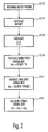
- FIG. 2 is a flowchart illustrating a determinant-maximizing CMG steering law
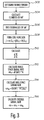
- FIG. 3 is a flowchart illustrating an eigenvalue-based steering law.
- the present invention takes advantage of null-space steering to prevent the occurrence of singularities when moving the CMGs in a CMG array to provide torque. Furthermore, the present invention does so in a way that optimally conditions the CMG array at all times, keeping the CMG array as far as possible from any singularity. As discussed previously, a minimum of three CMGs are required to provide the three degrees of freedom needed to orient a spacecraft. However, in many cases more than three CMGs are implemented. The extra CMGs are typically provided for mechanical redundancy purposes but are occasionally used in the implementation of sophisticated steering laws like the present invention. Each extra CMG provides an extra mathematical degree of freedom.
- a 3xn matrix A provides for a three-dimensional range space and a null space of dimension at least n-3.
- a matrix B can be defined as spanning the null space of matrix A.
- While movement of the CMGs in the null space does not affect the torque provided by the CMG array, the movement of the CMGs in the null space can affect how each CMG gimbal angle contributes to the total gimbal rate, ⁇ , an nx1 array, required to produce the torque: ⁇ ⁇ r + ⁇ n where ⁇ r is the portion of the total gimbal-rate vector that lies within the range space, and ⁇ n is the portion within the null space.
- FIG. 1 An exemplary control system 100 for implementing the present invention is illustrated in Fig. 1 .
- the components of the control system 100 are known in the art and can be assembled in different ways using different processors, software, controllers, sensors and the like.
- the control system 100 includes an attitude control system 102 coupled to a momentum actuator control processor 104.
- CMGs 106 are coupled the momentum actuator control processor 104.
- Associated with each CMG 106 are one or more CMG sensors 108 for providing information concerning the state of the CMG 106 to the control system.
- Control system 100 in one embodiment, is mounted on a spacecraft such as an orbiting satellite.
- Attitude control system 102 controls the positioning of a spacecraft.
- the attitude control system 102 receives data concerning a desired spacecraft maneuver and determines an appropriate torque command to complete the desired maneuver.
- the torque commands are presented to the momentum actuator control processor 104.
- the momentum actuator control processor 104 in response to the torque commands, calculates the gimbal rates necessary to produce the commanded torque. Additionally, the momentum actuator control processor 104 calculates CMG movement in both the range space and the null space to prevent singular conditions.
- the momentum actuator control system processor 104 based on the above identified calculations, provides the necessary commands to the CMGs 106 such that the CMG movement produces the commanded torque and, in accordance with the teachings of the present invention, provides the torque while preventing conditions that lead to a singularity.
- Individual CMGs are not necessarily devoted exclusively to range-space or null-space motion; rather, all of the CMGs, working in concert, produce both range-space and null-space effects.
- movement in the null space can be used to avoid singularities.
- the gimbal rates in the null space are determined such that det(AA T ) is maximized.
- Fig. 2 is a flowchart illustrating a method for maximizing the determinant of (AA T ) using null-space steering.
- step 202 the torque required to move the spacecraft is determined, in one embodiment by the attitude control system 102.
- step 204 the elements of the AA T matrix are calculated to determine the determinant.
- the result is an entirely analytical gradient-steering method, whose explicit solution for the gimbal motion eliminates the need for numerical search algorithms.
- g i the i th CMG's gimbal axis rate
- h i the i th CMG's angular momentum
- the matrix exponential e ⁇ i ⁇ g i x is used as a convenience in the derivation. In practice, this direction-cosine matrix is a simple function of the gimbal axis and sines and cosines of the gimbal angle.
- the matrix exponential e ⁇ i ⁇ g i x represents a rotation of an angle ⁇ about an axis g i .
- K is a matrix or scalar gain, either constant or otherwise, selected to ensure that the gimbal rate never exceeds a maximum value and so that, for all points in the CMG array's capability, the determinant, det(AA T ), is driven away from singularities faster than it is drawn to them.
- B ( B T B ) -1 B T projects the gimbal motion that would follow the gradient of the determinant exactly onto the null space so that it does not influence the output torque.
- ⁇ ⁇ ⁇ ⁇ is the partial derivative of the determinant with respect to the output torque direction.
- the components of this vector were previously calculated in step 206.
- the expression ⁇ ⁇ ⁇ ⁇ T is used as the pseudoinverse of ⁇ ⁇ ⁇ ⁇ .
- the traditional pseudoinverse includes a factor of one over the square of the magnitude. Since, in this case, the magnitude can never go to zero in the gimbal angle set, this term can be excluded. The result is a bell-behaved, stable, null-space command.
- the null-space steering maximizes a weighted sum of the eigenvalues of (AA T ).
- D a scalar, ⁇
- this embodiment also steers the CMGs in a way that attempts to optimize the determinant.
- the difference in this embodiment is that each of the eigenvalues can be treated individually, an approach that may offer more versatility in some applications.
- FIG. 3 is a flowchart illustrating an embodiment of the present invention that maximizes the eigenvalues of (AA T ) by null-space motion.
- the required torque is determined (step 302). This torque is the torque requested to change the attitude of the spacecraft.
- step 304 the elements of the matrix AA T are calculated. The elements of matrix AA T are calculated in the same manner as the first embodiment.
- step 306 the eigenvalues of AA T are calculated.
- the coefficients ⁇ , ⁇ and ⁇ are weighting factors that can be varied to emphasis a particular eigenvalue if desired. Alternatively, the coefficients can be given equal weight.
- ⁇ v i ⁇ ⁇ i and ⁇ J ⁇ v i can be computed analytically from the eigenvalues determined previously.
Landscapes
- Engineering & Computer Science (AREA)
- Remote Sensing (AREA)
- Chemical & Material Sciences (AREA)
- Combustion & Propulsion (AREA)
- Radar, Positioning & Navigation (AREA)
- Aviation & Aerospace Engineering (AREA)
- Automation & Control Theory (AREA)
- Control Of Position, Course, Altitude, Or Attitude Of Moving Bodies (AREA)
Applications Claiming Priority (2)
| Application Number | Priority Date | Filing Date | Title |
|---|---|---|---|
| US10/897,494 US7246776B2 (en) | 2004-07-23 | 2004-07-23 | Method and system for CMG array singularity avoidance |
| PCT/US2005/025614 WO2006085996A1 (en) | 2004-07-23 | 2005-07-18 | Method and system for cmg array singularity avoidance |
Publications (2)
| Publication Number | Publication Date |
|---|---|
| EP1776626A1 EP1776626A1 (en) | 2007-04-25 |
| EP1776626B1 true EP1776626B1 (en) | 2008-12-31 |
Family
ID=35756501
Family Applications (1)
| Application Number | Title | Priority Date | Filing Date |
|---|---|---|---|
| EP05856878A Expired - Lifetime EP1776626B1 (en) | 2004-07-23 | 2005-07-18 | Method and system for cmg array singularity avoidance |
Country Status (5)
| Country | Link |
|---|---|
| US (1) | US7246776B2 (enExample) |
| EP (1) | EP1776626B1 (enExample) |
| JP (1) | JP4630332B2 (enExample) |
| DE (1) | DE602005012109D1 (enExample) |
| WO (1) | WO2006085996A1 (enExample) |
Families Citing this family (16)
| Publication number | Priority date | Publication date | Assignee | Title |
|---|---|---|---|---|
| US7246776B2 (en) | 2004-07-23 | 2007-07-24 | Honeywell International, Inc. | Method and system for CMG array singularity avoidance |
| US7370833B2 (en) * | 2005-10-20 | 2008-05-13 | Honeywell International Inc. | Method and system for determining a singularity free momentum path |
| US7693619B2 (en) * | 2005-11-30 | 2010-04-06 | Honeywell International Inc. | Method and system for controlling sets of collinear control moment gyroscopes with offset determination without attitude trajectory of spacecraft |
| US7805226B2 (en) * | 2006-09-29 | 2010-09-28 | Honeywell International Inc. | Hierarchical strategy for singularity avoidance in arrays of control moment gyroscopes |
| US7627404B2 (en) * | 2007-04-13 | 2009-12-01 | The Boeing Company | Singularity escape and avoidance using a virtual array rotation |
| US8209070B2 (en) * | 2008-12-17 | 2012-06-26 | Honeywell International Inc. | Methods and systems for efficiently orienting an agile vehicle using a gyroscope array |
| US8014911B2 (en) * | 2009-11-03 | 2011-09-06 | Honeywell International Inc. | Methods and systems for imposing a momentum boundary while reorienting an agile vehicle with control moment gyroscopes |
| US8346538B2 (en) | 2010-05-25 | 2013-01-01 | Honeywell International Inc. | Methods and systems for reducing angular velocity using a gyroscope array |
| US9567112B1 (en) | 2013-06-27 | 2017-02-14 | The United States Of America, As Represented By The Secretary Of The Navy | Method and apparatus for singularity avoidance for control moment gyroscope (CMG) systems without using null motion |
| CN103940451B (zh) * | 2014-04-30 | 2016-08-24 | 北京控制工程研究所 | 基于零空间向量自主优化选择的冗余陀螺故障定位方法 |
| CN104044756B (zh) * | 2014-06-09 | 2016-04-27 | 中国科学院长春光学精密机械与物理研究所 | 高集成高精度控制力矩陀螺群伺服控制装置 |
| CN110712768B (zh) * | 2019-10-31 | 2021-03-16 | 上海航天控制技术研究所 | 一种控制力矩陀螺群初始框架位置确定方法 |
| CN112256048B (zh) * | 2020-10-13 | 2022-02-11 | 北京航空航天大学 | 一种混合灵敏度优化的cmg框架系统速度调节方法 |
| CN113247310B (zh) * | 2021-05-20 | 2022-07-29 | 上海卫星工程研究所 | 一种适用于卫星可连续姿态机动次数的估算方法及系统 |
| US20240308698A1 (en) * | 2023-03-08 | 2024-09-19 | The Boeing Company | Systems and methods for combined control moment gyroscope and thruster control |
| CN119160416B (zh) * | 2024-11-20 | 2025-02-25 | 杭州电子科技大学 | 一种基于前馈模型预测的立体成像卫星姿态控制方法 |
Family Cites Families (16)
| Publication number | Priority date | Publication date | Assignee | Title |
|---|---|---|---|---|
| FR2678894B1 (fr) * | 1991-07-09 | 1993-11-19 | Aerospatiale Ste Nationale Indle | Procede et dispositif de controle d'attitude en roulis-lacet d'un satellite a direction unique d'actionnement continu. |
| US5875676A (en) * | 1997-09-02 | 1999-03-02 | Honeywell Inc. | Non colocated rate sensing for control moment gyroscopes |
| US6154691A (en) * | 1997-09-02 | 2000-11-28 | Honeywell International Inc. | Orienting a satellite with controlled momentum gyros |
| US6047927A (en) * | 1998-03-16 | 2000-04-11 | Honeywell Inc. | Escaping singularities in a satellite attitude control |
| US6128556A (en) * | 1998-03-16 | 2000-10-03 | Honeywell International Inc. | CMG control based on angular momentum to control satellite attitude |
| US6131056A (en) | 1998-03-16 | 2000-10-10 | Honeywell International Inc. | Continuous attitude control that avoids CMG array singularities |
| US6039290A (en) | 1998-03-16 | 2000-03-21 | Honeywell Inc. | Robust singularity avoidance in satellite attitude control |
| US6360996B1 (en) * | 2000-02-24 | 2002-03-26 | Hughes Electronics Corporation | Steering control for skewed scissors pair CMG clusters |
| US6354163B1 (en) | 2000-05-17 | 2002-03-12 | Honeywell International Inc. | Mitigating gimbal induced disturbances in CMG arrays |
| JP2002145199A (ja) * | 2000-11-13 | 2002-05-22 | Toshiba Corp | 宇宙航行体の姿勢制御装置 |
| FR2826470B1 (fr) * | 2001-06-26 | 2003-09-19 | Astrium Sas | Procede et dispositif de pilotage de l'attitude et de guidage d'un satellite par grappe de gyrodynes |
| US6681649B2 (en) * | 2002-04-03 | 2004-01-27 | Honeywell International Inc. | Inertial control and measurement system |
| US6648274B1 (en) * | 2002-04-12 | 2003-11-18 | David A. Bailey | Virtual reaction wheel array |
| US6917862B2 (en) * | 2002-08-28 | 2005-07-12 | Arizona Board Of Regents | Singularity escape/avoidance steering logic for control moment gyro systems |
| JP3970724B2 (ja) * | 2002-08-30 | 2007-09-05 | Nec東芝スペースシステム株式会社 | 飛翔体の姿勢変更制御装置及び姿勢変更制御方法 |
| US7246776B2 (en) | 2004-07-23 | 2007-07-24 | Honeywell International, Inc. | Method and system for CMG array singularity avoidance |
-
2004
- 2004-07-23 US US10/897,494 patent/US7246776B2/en not_active Expired - Lifetime
-
2005
- 2005-07-18 JP JP2007522662A patent/JP4630332B2/ja not_active Expired - Fee Related
- 2005-07-18 WO PCT/US2005/025614 patent/WO2006085996A1/en not_active Ceased
- 2005-07-18 DE DE602005012109T patent/DE602005012109D1/de not_active Expired - Lifetime
- 2005-07-18 EP EP05856878A patent/EP1776626B1/en not_active Expired - Lifetime
Also Published As
| Publication number | Publication date |
|---|---|
| DE602005012109D1 (de) | 2009-02-12 |
| WO2006085996A1 (en) | 2006-08-17 |
| US7246776B2 (en) | 2007-07-24 |
| JP2008507446A (ja) | 2008-03-13 |
| EP1776626A1 (en) | 2007-04-25 |
| JP4630332B2 (ja) | 2011-02-09 |
| US20060027708A1 (en) | 2006-02-09 |
Similar Documents
| Publication | Publication Date | Title |
|---|---|---|
| EP1776626B1 (en) | Method and system for cmg array singularity avoidance | |
| US7627404B2 (en) | Singularity escape and avoidance using a virtual array rotation | |
| US8880246B1 (en) | Method and apparatus for determining spacecraft maneuvers | |
| EP1782143B1 (en) | Method and system for optimizing torque in a cmg array | |
| EP1908686B1 (en) | Hierarchial strategy for singularity avoidance in arrays of control moment gyroscopes | |
| US11292618B2 (en) | Nonlinear model predictive control of coupled celestial system | |
| US12240631B2 (en) | Orbital attitude control device, satellite, orbital attitude control method, and recording medium | |
| Jones et al. | Generalized framework for linearly constrained control moment gyro steering | |
| Sugihara et al. | Design, Control, and Motion Strategy of TRADY: Tilted‐Rotor‐Equipped Aerial Robot With Autonomous In‐Flight Assembly and Disassembly Ability | |
| US9567112B1 (en) | Method and apparatus for singularity avoidance for control moment gyroscope (CMG) systems without using null motion | |
| EP1749743B1 (en) | A method and system for determining a singularity free momentum path | |
| US7370833B2 (en) | Method and system for determining a singularity free momentum path | |
| US20070124032A1 (en) | Method and system for controlling sets of collinear control moment gyroscopes | |
| US20040193292A1 (en) | Robust spacecraft controller and method for designing same | |
| Sasaki et al. | Gain-scheduled control/steering design for a spacecraft with variable-speed control moment gyros | |
| Takada et al. | Receding horizon control on steering of control moment gyro for fast attitude maneuver | |
| Okubo et al. | Singularity robust steering of redundant single gimbal control moment gyros for small satellites | |
| Facchino | MPC Design for CMG based Testbed | |
| Sasaki | Convex Optimization for Attitude, Vibration, and Orbit Control of a Spacecraft with Double-Gimbal Variable-Speed Control Moment Gyros | |
| Leve | Design of 3-DOF Testbed for Micro-Satellite Autonomous Operations | |
| Dionne et al. | Rapid Slew and Settle of a Small Satellite in LEO Laser Communication | |
| 權相元 | Attitude Control of Small Satellites Using Single-Gimbal Control Moment Gyros |
Legal Events
| Date | Code | Title | Description |
|---|---|---|---|
| PUAI | Public reference made under article 153(3) epc to a published international application that has entered the european phase |
Free format text: ORIGINAL CODE: 0009012 |
|
| 17P | Request for examination filed |
Effective date: 20070119 |
|
| AK | Designated contracting states |
Kind code of ref document: A1 Designated state(s): DE FR GB IT |
|
| RIN1 | Information on inventor provided before grant (corrected) |
Inventor name: PECK, MASON, A. Inventor name: UNDERHILL, BRIAN Inventor name: HAMILTON, BRIAN, J. |
|
| DAX | Request for extension of the european patent (deleted) | ||
| RBV | Designated contracting states (corrected) |
Designated state(s): DE FR GB IT |
|
| GRAP | Despatch of communication of intention to grant a patent |
Free format text: ORIGINAL CODE: EPIDOSNIGR1 |
|
| GRAS | Grant fee paid |
Free format text: ORIGINAL CODE: EPIDOSNIGR3 |
|
| GRAA | (expected) grant |
Free format text: ORIGINAL CODE: 0009210 |
|
| AK | Designated contracting states |
Kind code of ref document: B1 Designated state(s): DE FR GB IT |
|
| REG | Reference to a national code |
Ref country code: GB Ref legal event code: FG4D |
|
| REF | Corresponds to: |
Ref document number: 602005012109 Country of ref document: DE Date of ref document: 20090212 Kind code of ref document: P |
|
| PLBE | No opposition filed within time limit |
Free format text: ORIGINAL CODE: 0009261 |
|
| STAA | Information on the status of an ep patent application or granted ep patent |
Free format text: STATUS: NO OPPOSITION FILED WITHIN TIME LIMIT |
|
| PGFP | Annual fee paid to national office [announced via postgrant information from national office to epo] |
Ref country code: GB Payment date: 20090612 Year of fee payment: 5 |
|
| 26N | No opposition filed |
Effective date: 20091001 |
|
| PGFP | Annual fee paid to national office [announced via postgrant information from national office to epo] |
Ref country code: IT Payment date: 20090722 Year of fee payment: 5 |
|
| GBPC | Gb: european patent ceased through non-payment of renewal fee |
Effective date: 20100718 |
|
| PG25 | Lapsed in a contracting state [announced via postgrant information from national office to epo] |
Ref country code: IT Free format text: LAPSE BECAUSE OF NON-PAYMENT OF DUE FEES Effective date: 20100718 |
|
| PG25 | Lapsed in a contracting state [announced via postgrant information from national office to epo] |
Ref country code: GB Free format text: LAPSE BECAUSE OF NON-PAYMENT OF DUE FEES Effective date: 20100718 |
|
| REG | Reference to a national code |
Ref country code: FR Ref legal event code: PLFP Year of fee payment: 12 |
|
| REG | Reference to a national code |
Ref country code: FR Ref legal event code: PLFP Year of fee payment: 13 |
|
| REG | Reference to a national code |
Ref country code: FR Ref legal event code: PLFP Year of fee payment: 14 |
|
| PGFP | Annual fee paid to national office [announced via postgrant information from national office to epo] |
Ref country code: DE Payment date: 20210729 Year of fee payment: 17 |
|
| REG | Reference to a national code |
Ref country code: DE Ref legal event code: R119 Ref document number: 602005012109 Country of ref document: DE |
|
| PG25 | Lapsed in a contracting state [announced via postgrant information from national office to epo] |
Ref country code: DE Free format text: LAPSE BECAUSE OF NON-PAYMENT OF DUE FEES Effective date: 20230201 |
|
| P01 | Opt-out of the competence of the unified patent court (upc) registered |
Effective date: 20230525 |
|
| PGFP | Annual fee paid to national office [announced via postgrant information from national office to epo] |
Ref country code: FR Payment date: 20240725 Year of fee payment: 20 |