EP1775493A1 - Sliding caliper disc brake - Google Patents
Sliding caliper disc brake Download PDFInfo
- Publication number
- EP1775493A1 EP1775493A1 EP05022384A EP05022384A EP1775493A1 EP 1775493 A1 EP1775493 A1 EP 1775493A1 EP 05022384 A EP05022384 A EP 05022384A EP 05022384 A EP05022384 A EP 05022384A EP 1775493 A1 EP1775493 A1 EP 1775493A1
- Authority
- EP
- European Patent Office
- Prior art keywords
- brake
- bridge
- disc
- brake pad
- caliper
- Prior art date
- Legal status (The legal status is an assumption and is not a legal conclusion. Google has not performed a legal analysis and makes no representation as to the accuracy of the status listed.)
- Granted
Links
- 238000009434 installation Methods 0.000 description 4
- 239000000725 suspension Substances 0.000 description 4
- 238000012423 maintenance Methods 0.000 description 2
- 230000006641 stabilisation Effects 0.000 description 2
- 238000011105 stabilization Methods 0.000 description 2
- 230000000087 stabilizing effect Effects 0.000 description 2
- 230000005540 biological transmission Effects 0.000 description 1
- 238000010276 construction Methods 0.000 description 1
- 230000014509 gene expression Effects 0.000 description 1
- 230000002093 peripheral effect Effects 0.000 description 1
Images




Classifications
-
- F—MECHANICAL ENGINEERING; LIGHTING; HEATING; WEAPONS; BLASTING
- F16—ENGINEERING ELEMENTS AND UNITS; GENERAL MEASURES FOR PRODUCING AND MAINTAINING EFFECTIVE FUNCTIONING OF MACHINES OR INSTALLATIONS; THERMAL INSULATION IN GENERAL
- F16D—COUPLINGS FOR TRANSMITTING ROTATION; CLUTCHES; BRAKES
- F16D55/00—Brakes with substantially-radial braking surfaces pressed together in axial direction, e.g. disc brakes
- F16D55/02—Brakes with substantially-radial braking surfaces pressed together in axial direction, e.g. disc brakes with axially-movable discs or pads pressed against axially-located rotating members
- F16D55/22—Brakes with substantially-radial braking surfaces pressed together in axial direction, e.g. disc brakes with axially-movable discs or pads pressed against axially-located rotating members by clamping an axially-located rotating disc between movable braking members, e.g. movable brake discs or brake pads
- F16D55/224—Brakes with substantially-radial braking surfaces pressed together in axial direction, e.g. disc brakes with axially-movable discs or pads pressed against axially-located rotating members by clamping an axially-located rotating disc between movable braking members, e.g. movable brake discs or brake pads with a common actuating member for the braking members
- F16D55/225—Brakes with substantially-radial braking surfaces pressed together in axial direction, e.g. disc brakes with axially-movable discs or pads pressed against axially-located rotating members by clamping an axially-located rotating disc between movable braking members, e.g. movable brake discs or brake pads with a common actuating member for the braking members the braking members being brake pads
- F16D55/226—Brakes with substantially-radial braking surfaces pressed together in axial direction, e.g. disc brakes with axially-movable discs or pads pressed against axially-located rotating members by clamping an axially-located rotating disc between movable braking members, e.g. movable brake discs or brake pads with a common actuating member for the braking members the braking members being brake pads in which the common actuating member is moved axially, e.g. floating caliper disc brakes
-
- F—MECHANICAL ENGINEERING; LIGHTING; HEATING; WEAPONS; BLASTING
- F16—ENGINEERING ELEMENTS AND UNITS; GENERAL MEASURES FOR PRODUCING AND MAINTAINING EFFECTIVE FUNCTIONING OF MACHINES OR INSTALLATIONS; THERMAL INSULATION IN GENERAL
- F16D—COUPLINGS FOR TRANSMITTING ROTATION; CLUTCHES; BRAKES
- F16D65/00—Parts or details
- F16D65/02—Braking members; Mounting thereof
- F16D65/04—Bands, shoes or pads; Pivots or supporting members therefor
- F16D65/092—Bands, shoes or pads; Pivots or supporting members therefor for axially-engaging brakes, e.g. disc brakes
- F16D65/095—Pivots or supporting members therefor
-
- F—MECHANICAL ENGINEERING; LIGHTING; HEATING; WEAPONS; BLASTING
- F16—ENGINEERING ELEMENTS AND UNITS; GENERAL MEASURES FOR PRODUCING AND MAINTAINING EFFECTIVE FUNCTIONING OF MACHINES OR INSTALLATIONS; THERMAL INSULATION IN GENERAL
- F16D—COUPLINGS FOR TRANSMITTING ROTATION; CLUTCHES; BRAKES
- F16D55/00—Brakes with substantially-radial braking surfaces pressed together in axial direction, e.g. disc brakes
- F16D2055/0004—Parts or details of disc brakes
- F16D2055/0008—Brake supports
-
- F—MECHANICAL ENGINEERING; LIGHTING; HEATING; WEAPONS; BLASTING
- F16—ENGINEERING ELEMENTS AND UNITS; GENERAL MEASURES FOR PRODUCING AND MAINTAINING EFFECTIVE FUNCTIONING OF MACHINES OR INSTALLATIONS; THERMAL INSULATION IN GENERAL
- F16D—COUPLINGS FOR TRANSMITTING ROTATION; CLUTCHES; BRAKES
- F16D55/00—Brakes with substantially-radial braking surfaces pressed together in axial direction, e.g. disc brakes
- F16D2055/0004—Parts or details of disc brakes
- F16D2055/0016—Brake calipers
- F16D2055/002—Brake calipers assembled from a plurality of parts
Definitions
- the present invention concerns disc brakes with a sliding caliper which is arranged in sliding engagement on a carrier which is fixed to the axle.
- the caliper contains a brake actuating mechanism which is applying a brake force so that brake pads which are arranged on both sides of a brake disc come into braking engagement with the latter.
- the disc brake is primarily intended for a road vehicle but may quite as well be used for a rail vehicle.
- Sliding calipers require certain space for their movement during brake actuation in the axial direction of the brake disc.
- the location of other components such as the suspension, the steering axle or the wheel rim have to be considered during construction and assembly of the calipers so that always free movement of the latter is ensured.
- access to the calipers should be possible for maintenance reasons and for disassembly for exchanging worn brake pads, the brake disc or other components.
- the caliper is divided mainly in two parts, a housing which is arranged astraddle of the brake disc and a cover which is fixed to the housing by way of bolts.
- the cover comprises at least some parts of the brake actuating mechanism and constitutes a self-sustained unit with said parts which enables the insert of the unit into the housing of the caliper through an opening arranged on the rear side of the caliper, i.e. the side opposite to the wheel.
- a further object of the present invention is accordingly to facilitate the mounting of the disc brake and parts thereof under such tight installation conditions.
- the present invention addresses the afore-mentioned problems, which occur in such disc brakes as defined.
- the disc brake according to the present invention comprises a sliding caliper in two part-form with a housing and a bridge.
- the housing which receives a brake actuating mechanism for the application of a brake force, is to be arranged astraddle of a brake disc and comprises two legs in parallel which overlap said brake disc. To the free end front surfaces of said legs, the bridge is fixed by means of bolts. In other words, the bridge of the caliper is arranged on the side of the brake disc opposite of the brake actuating mechanism.
- Both the housing and the bridge of the caliper are arranged in sliding engagement with a carrier by means of guide pins, respectively.
- the carrier remains stationary and is fixed to the axle of the vehicle.
- brake pads are arranged for braking engagement with the brake disc, one inner brake pad, which directly cooperates with the brake actuating mechanism, being arranged on the application-side of the brake disc and one outer brake pad being arranged on the reaction-side of the brake disc.
- the bridge is designed and configured in such a way so that, when mounted to the housing of the caliper, said bridge is stabilizing and/or guiding the outer brake pad in the caliper.
- the outer brake pad can be easily mounted. Further, easy access to the carrier and the brake disc is provided, when the bridge gets dismounted, which facilitates assembly of these parts and maintenance.
- One major advantage of the caliper design according to the invention is due to the fact that no heads of bolts could interfere with the suspension or other peripheral components, since the bolts for the fixation of the bridge are located on the outer side of the caliper only.
- the overall dimensions of the caliper can be more easily designed with respect to the present space requirements and with respect to the assembly of the caliper under such space requirements, such as e.g. for super small wheel rims.
- the inner brake pad as it is commonly known, is supported by the carrier, whereas according to the invention the outer brake pad is supported by the caliper.
- the tangential forces which will be exerted by the brake pads substantially in the rotational direction of the brake disc due to the frictional engagement between the latter and the brake pads, will be taken up by the carrier for the inner brake pad and by the caliper for the outer brake pad.
- the outer brake pad is supported by the legs of the housing which take up the tangential forces.
- each leg of the housing comprises a support face in substantially vertical orientation. Both vertical support faces do face each other and serve as an abutment for the short sides of the outer brake pad, respectively.
- the carrier is comprising at least one horizontal support face for the outer brake pad, similar as for the inner brake pad.
- at least one horizontal support face is arranged on the side of the bridge facing the brake disc.
- the bridge is stabilizing and locating the outer brake pad in position and for guidance, when the bridge is bolted to the legs of the housing.
- such stabilization and guidance of the outer brake pad is realized by substantially vertical support faces which are arranged on the inner side of the bridge and which face each other.
- said vertical support faces are formed integrally with the bridge as one piece.
- horizontal support faces for the outer brake pad can be either arranged on the carrier or on the bridge directly.
- the bridge comprises a recess to be formed on its inner side which substantially corresponds in shape to the geometric shape of the outer brake pad.
- the recess can be formed with a certain degree of clearance, in particular in the tangential directions, so as to allow for the tangential movement of the brake pads to some extent during braking.
- This embodiment has the advantage that the outer brake pad is entirely guided by the recess in the bridge which at the same time avoids noise and vibrations so that no more additional dampening spring for the outer brake pad is needed.
- the bridge serves as the means to stabilize the outer brake pad for its locating and guidance during and after the mounting of the bridge to the housing.
- outer and inner are used to describe the placement of components, or parts of components, as seen in an axial direction from the centre of the vehicle, “outer” means a placement more far from the vehicle centre-line to the side of the vehicle.
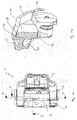
- Fig. 1 a first embodiment of the disc brake according to the invention is shown in an exploded perspective view.
- the disc brake comprises a caliper 1 which consists of two parts, an inner housing 2 and an outer bridge 3.
- the housing 2 receives a brake actuating mechanism, two thrust tappets 4 of which can be seen on the side of the housing 2 facing the brake disc.
- the housing 2 is preferably cast as one piece an comprises two parallel legs 5 which are arranged astraddle the brake disc, as can be seen e.g. in Fig. 2, and which end in a free end front surface 6, respectively.
- the bridge 3 is mounted with corresponding front surfaces 7 by means of bolts 8, whereby the two part-caliper 1 will be completed.
- the housing 2 and the bridge 3 do embed brake pads, an inner brake pad 9 and an outer brake pad 10, which are arranged on both sides of the brake disc (not shown), respectively.
- Each brake pad 9 and 10 is formed integral with a back plate 11, respectively.
- a carrier 12 is arranged between the housing 2 and the bridge 3 and is fixed to an axle by intermediate parts (not shown).
- the carrier 12 receives the caliper 1 in a sliding manner.
- the carrier 12 comprises guide pins 13 which are received by sleeves 14 in the housing 2.
- the bridge 3 comprises guide pins 15 which interact with sleeves 16 of the carrier 12.
- the inner brake pad 9 with its back plate 11 is supported on the inner side of the substantially U-shaped carrier 12 by means of supports 17, which are formed integral with the carrier 12 and embed the inner brake pad 9 and its back plate 11 so as to receive tangential forces from the inner brake pad 9 and its back plate 11 when being in engagement with the brake disc during braking after the thrust tappets 4 pushed the inner brake pad 9 forward.
- the outer brake pad 10 and its back plate 11 are supported by the housing 2, as can be seen from Figs. 3a and 3b, which housing 2 receives the tangential forces of the outer brake pad 10 and its back plate 11.
- the legs 5 of the housing 2 comprise in the region of their free end front surfaces 6 vertical supports faces 18, which face each other and against which the short sides of the outer brake pad 10 and/or its back plate 11 abut during the braking engagement.
- outer brake pad 10 is guided on horizontal support faces 19, which are provided by the carrier 12 and can better be seen in Figs. 6a and 6b.
- the outer brake pad 10 will be stabilized and located in position by the bridge 3, when the latter is mounted to the housing 2 after assembly of the caliper 1.
- a second embodiment of the caliper 1 of the disc brake according to the invention is shown in exploded perspective view.
- this second embodiment corresponds to the first embodiment with the difference that the support for the outer brake pad 10 and its back plate 11 is provided by the bridge 3 directly.
- the bridge 3 comprises for that purpose substantially vertical support faces 20 which face each other and which preferably are integrally formed with the bridge 3 at the side facing the brake disc as one piece. As can be seen from Fig. 6b, the vertical support faces 20 of the bridge 3 are configured so that only the back plate 11 of the outer brake pad 10 abuts against the faces 20.
- the outer brake pad 10 is horizontally guided by the horizontal support faces 19 of the carrier 12.
- the vertical support faces 20 of the bridge 3 in turn are supported on both sides by abutments 21, which are arranged at the free end regions of the legs 5 of the housing 2. Thereby, the tangential forces taken up by the vertical support faces 20 of the bridge 3 are then directly transferred into the housing 2.
- Fig. 7 a third embodiment of a disc brake according to the invention is disclosed.
- the third embodiment substantially corresponds to the first embodiment with the difference that the bridge 3 is comprising a horizontal support face 22 for the outer brake pad 10 and its back plate 11.
- said horizontal support face 22 is received in the space formed by two free opposite ends 23 in the outer side of the carrier 12.
- the horizontal support face 22 receives only the back plate 11 of the outer brake pad 10.
- the back plate 11 is again supported by the vertical support faces 18 of the legs 5 of the housing 2.
- Figs. 10 to 12c show a preferred embodiment of the disc brake according to the invention, which basically differs from the three embodiments as described above.
- Fig. 10 said fourth embodiment is shown in exploded perspective view.
- the carrier 12 is of an open design and comprises two ends 23.
- the bridge 3 better to be seen in Figs. 12a to 12c, comprises both the horizontal support faces and the vertical support faces for the guidance and stabilization of the outer brake pad 10. According to the invention this is realized by a recess 24 which is formed at the inner side of the bridge 3 facing the brake disc.
- the shape of said recess 24 corresponds to the shape of the outer brake pad 10 to be received by the recess 24 thereby forming an upper substantially horizontal support face 25 and lower horizontal support faces 26 on the one hand and vertical support faces 27 on both sides of the recess 24 on the other hand which face each other and against which the short sides of the outer brake pad 10 abut during braking.
- the outer brake pad 10 does not have a back plate as the bridge 3 itself forms the back plate for the brake pad 10.
- the outer brake pad 10 is received in the recess 24 without tolerance so that the brake pad 10 cannot move during braking engagement.
- the outer brake pad 10 is received in the recess 24 with some tolerance, as the recess 24 offers some clearance 28 between the respective support faces 25, 26, 27 and the edges of the outer brake pad 10, which allows for minor movements during the braking engagement.
- the back side of the bridge 3 is configured with a recess 29 on the one hand and the different wall thicknesses of the bridge 3 are designed on the other hand so as to allow for best force and stress distribution and support in the bridge 3.
- the shape of the recess 24 and the outer brake pad 10 may vary accordingly.
- the bridge 3 actually serves to stabilize the outer brake pad 10 with regard to the carrier 12 and the brake disc, which facilitates the guidance and its locating of the outer brake pad 10.
Landscapes
- Engineering & Computer Science (AREA)
- General Engineering & Computer Science (AREA)
- Mechanical Engineering (AREA)
- Braking Arrangements (AREA)
Abstract
Description
- The present invention concerns disc brakes with a sliding caliper which is arranged in sliding engagement on a carrier which is fixed to the axle. The caliper contains a brake actuating mechanism which is applying a brake force so that brake pads which are arranged on both sides of a brake disc come into braking engagement with the latter. The disc brake is primarily intended for a road vehicle but may quite as well be used for a rail vehicle.
- Sliding calipers require certain space for their movement during brake actuation in the axial direction of the brake disc. In close proximity of the disc brake for a wheel, however, the location of other components such as the suspension, the steering axle or the wheel rim have to be considered during construction and assembly of the calipers so that always free movement of the latter is ensured. Further, access to the calipers should be possible for maintenance reasons and for disassembly for exchanging worn brake pads, the brake disc or other components.
- This, however, will become a major problem under very tight installation conditions, such as, for example, the use of super single wheel rims or the arrangement of the disc brake in very close proximity to the suspension. In particular, when a so-called two part-caliper is used, as it is known e.g. from the applicant's
European patent EP 0 942 191 B2 , the specific design of such calipers may interfere with such constructional space constraints. - In
EP 0 942 191 B2 the caliper is divided mainly in two parts, a housing which is arranged astraddle of the brake disc and a cover which is fixed to the housing by way of bolts. The cover comprises at least some parts of the brake actuating mechanism and constitutes a self-sustained unit with said parts which enables the insert of the unit into the housing of the caliper through an opening arranged on the rear side of the caliper, i.e. the side opposite to the wheel. - When such a caliper is mounted in very tight installation environments as described above, some drawbacks might be present. Under certain unfavourable conditions, if, for example, on the one hand, new brake pads are mounted in the disc brake, the caliper housing might get into contact with the wheel rim. On the other hand, if the brake pads are worn, the head of the bolts of the cover or parts of the cover itself might get into contact with parts of the suspension. It is obvious that such conditions are undesirable both as regards noise and functioning.
- It is accordingly an object of the present invention to enable free movement of a caliper under all conditions also in tight installation environments.
- A further object of the present invention is accordingly to facilitate the mounting of the disc brake and parts thereof under such tight installation conditions.
- The present invention addresses the afore-mentioned problems, which occur in such disc brakes as defined.
- In particular, the disc brake according to the present invention comprises a sliding caliper in two part-form with a housing and a bridge.
- The housing, which receives a brake actuating mechanism for the application of a brake force, is to be arranged astraddle of a brake disc and comprises two legs in parallel which overlap said brake disc. To the free end front surfaces of said legs, the bridge is fixed by means of bolts. In other words, the bridge of the caliper is arranged on the side of the brake disc opposite of the brake actuating mechanism.
- Both the housing and the bridge of the caliper are arranged in sliding engagement with a carrier by means of guide pins, respectively. The carrier remains stationary and is fixed to the axle of the vehicle.
- On both sides of the brake disc, brake pads are arranged for braking engagement with the brake disc, one inner brake pad, which directly cooperates with the brake actuating mechanism, being arranged on the application-side of the brake disc and one outer brake pad being arranged on the reaction-side of the brake disc.
- According to the invention, the bridge is designed and configured in such a way so that, when mounted to the housing of the caliper, said bridge is stabilizing and/or guiding the outer brake pad in the caliper.
- In other words, due to the fact that the bridge is arranged on the outer side of the caliper, the outer brake pad can be easily mounted. Further, easy access to the carrier and the brake disc is provided, when the bridge gets dismounted, which facilitates assembly of these parts and maintenance.
- One major advantage of the caliper design according to the invention is due to the fact that no heads of bolts could interfere with the suspension or other peripheral components, since the bolts for the fixation of the bridge are located on the outer side of the caliper only.
- Moreover, due to the two part-design with the specific housing comprising legs and the bridge, the overall dimensions of the caliper can be more easily designed with respect to the present space requirements and with respect to the assembly of the caliper under such space requirements, such as e.g. for super small wheel rims.
- This is further facilitated in that the inner brake pad, as it is commonly known, is supported by the carrier, whereas according to the invention the outer brake pad is supported by the caliper. During braking the tangential forces, which will be exerted by the brake pads substantially in the rotational direction of the brake disc due to the frictional engagement between the latter and the brake pads, will be taken up by the carrier for the inner brake pad and by the caliper for the outer brake pad.
- According to one aspect of the invention, the outer brake pad is supported by the legs of the housing which take up the tangential forces. At the regions of their free end front surfaces, each leg of the housing comprises a support face in substantially vertical orientation. Both vertical support faces do face each other and serve as an abutment for the short sides of the outer brake pad, respectively.
- In one embodiment, the carrier is comprising at least one horizontal support face for the outer brake pad, similar as for the inner brake pad. In another embodiment, at least one horizontal support face is arranged on the side of the bridge facing the brake disc. In both embodiments, the bridge is stabilizing and locating the outer brake pad in position and for guidance, when the bridge is bolted to the legs of the housing.
- In an alternative embodiment according to another aspect of the invention, such stabilization and guidance of the outer brake pad is realized by substantially vertical support faces which are arranged on the inner side of the bridge and which face each other. Preferably, said vertical support faces are formed integrally with the bridge as one piece. For further support and transmission of the tangential forces exerted by the outer brake pad during braking, said vertical support faces do abut against corresponding support faces which are formed on the legs of the housing at the region of their free ends. Also here, horizontal support faces for the outer brake pad can be either arranged on the carrier or on the bridge directly.
- In a preferred embodiment according to the invention, in which both the horizontal and the vertical support faces are provided by the bridge, the bridge comprises a recess to be formed on its inner side which substantially corresponds in shape to the geometric shape of the outer brake pad. The recess can be formed with a certain degree of clearance, in particular in the tangential directions, so as to allow for the tangential movement of the brake pads to some extent during braking.
- This embodiment has the advantage that the outer brake pad is entirely guided by the recess in the bridge which at the same time avoids noise and vibrations so that no more additional dampening spring for the outer brake pad is needed.
- In all embodiments, the bridge serves as the means to stabilize the outer brake pad for its locating and guidance during and after the mounting of the bridge to the housing.
- Further objects and advantages of the present invention will become obvious for a person skilled in the art when reading the detailed description below of preferred embodiments.
- The invention will be explained further below by way of examples and with reference to the enclosed drawings. In the drawings:
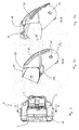
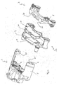
- Fig. 1 is an exploded perspective view of a first embodiment of a disc brake according to the invention;
- Fig. 2 is a top view of the embodiment of Fig. 1;
- Fig. 3a is a partial cross-section along X-X of Fig. 2;
- Fig. 3b is the partial cross-section of Fig. 3a shown in a perspective view;
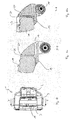
- Fig. 4 is an exploded perspective view of a second embodiment of a disc brake according to the invention;
- Fig. 5 is a top view of the embodiment of Fig. 4;
- Fig. 6a is a partial cross-section along Y-Y of Fig. 5;
- Fig. 6b is partial the cross-section of Fig. 6a shown in a perspective view;
- Fig. 7 is an exploded perspective view of a third embodiment of a disc brake according to the invention;
- Fig. 8 is a top view of the embodiment of Fig. 7;
- Fig. 9a is a partial cross-section along Z-Z of Fig. 8;
- Fig. 9b is the partial cross-section of Fig. 9a shown in a perspective view;
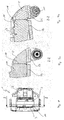
- Fig. 10 is an exploded view of a fourth embodiment of a disc brake according to the invention;
- Fig. 11 is a top view of the embodiment of Fig. 10;
- Fig. 12a is a partial cross-section along T-T of Fig. 11;
- Fig. 12b is the partial cross-section of Fig. 12a shown in a perspective view; and
- Fig. 12c is a partial cross-section along S-S of Fig. 11 shown in perspective view.
- As used in this description the expressions "outer" and "inner" are used to describe the placement of components, or parts of components, as seen in an axial direction from the centre of the vehicle, "outer" means a placement more far from the vehicle centre-line to the side of the vehicle.
- Identical or similar components in the different embodiments are bearing the same reference numerals. A person skilled in the art realises that the principles of the present invention apply for disc brakes having many different structures. Only parts important for the understanding of the present invention will be specifically referred to in the description below. For the ease of better illustration, the brake disc is not shown in the Figures.
- In Fig. 1 a first embodiment of the disc brake according to the invention is shown in an exploded perspective view.
- The disc brake comprises a caliper 1 which consists of two parts, an
inner housing 2 and anouter bridge 3. Thehousing 2 receives a brake actuating mechanism, two thrust tappets 4 of which can be seen on the side of thehousing 2 facing the brake disc. - The
housing 2 is preferably cast as one piece an comprises two parallel legs 5 which are arranged astraddle the brake disc, as can be seen e.g. in Fig. 2, and which end in a free end front surface 6, respectively. - To each of said free end front surfaces 6 of the legs 5, the
bridge 3 is mounted with corresponding front surfaces 7 by means ofbolts 8, whereby the two part-caliper 1 will be completed. - The
housing 2 and thebridge 3 do embed brake pads, an inner brake pad 9 and anouter brake pad 10, which are arranged on both sides of the brake disc (not shown), respectively. Eachbrake pad 9 and 10 is formed integral with aback plate 11, respectively. - A
carrier 12 is arranged between thehousing 2 and thebridge 3 and is fixed to an axle by intermediate parts (not shown). Thecarrier 12 receives the caliper 1 in a sliding manner. - For that purposes the
carrier 12 comprises guide pins 13 which are received bysleeves 14 in thehousing 2. Further, thebridge 3 comprises guide pins 15 which interact withsleeves 16 of thecarrier 12. Thereby, the caliper 1, i.e. thehousing 2 and thebridge 3 bolted thereto, can slide with respect to thecarrier 12 as one unit. - As can be seen in Fig. 1, the inner brake pad 9 with its
back plate 11 is supported on the inner side of the substantiallyU-shaped carrier 12 by means ofsupports 17, which are formed integral with thecarrier 12 and embed the inner brake pad 9 and itsback plate 11 so as to receive tangential forces from the inner brake pad 9 and itsback plate 11 when being in engagement with the brake disc during braking after the thrust tappets 4 pushed the inner brake pad 9 forward. - On contrary thereto, the
outer brake pad 10 and itsback plate 11 are supported by thehousing 2, as can be seen from Figs. 3a and 3b, whichhousing 2 receives the tangential forces of theouter brake pad 10 and itsback plate 11. - For that purpose, the legs 5 of the
housing 2 comprise in the region of their free end front surfaces 6 vertical supports faces 18, which face each other and against which the short sides of theouter brake pad 10 and/or itsback plate 11 abut during the braking engagement. - In addition, the
outer brake pad 10 is guided on horizontal support faces 19, which are provided by thecarrier 12 and can better be seen in Figs. 6a and 6b. - As can be seen from Fig. 1, the
outer brake pad 10 will be stabilized and located in position by thebridge 3, when the latter is mounted to thehousing 2 after assembly of the caliper 1. - In Fig. 4 a second embodiment of the caliper 1 of the disc brake according to the invention is shown in exploded perspective view.
- In principle this second embodiment corresponds to the first embodiment with the difference that the support for the
outer brake pad 10 and itsback plate 11 is provided by thebridge 3 directly. - The
bridge 3 comprises for that purpose substantially vertical support faces 20 which face each other and which preferably are integrally formed with thebridge 3 at the side facing the brake disc as one piece. As can be seen from Fig. 6b, the vertical support faces 20 of thebridge 3 are configured so that only theback plate 11 of theouter brake pad 10 abuts against the faces 20. - Also in this embodiment, the
outer brake pad 10 is horizontally guided by the horizontal support faces 19 of thecarrier 12. - The vertical support faces 20 of the
bridge 3 in turn are supported on both sides byabutments 21, which are arranged at the free end regions of the legs 5 of thehousing 2. Thereby, the tangential forces taken up by the vertical support faces 20 of thebridge 3 are then directly transferred into thehousing 2. - In Fig. 7 a third embodiment of a disc brake according to the invention is disclosed.
- The third embodiment substantially corresponds to the first embodiment with the difference that the
bridge 3 is comprising ahorizontal support face 22 for theouter brake pad 10 and itsback plate 11. When thebridge 3 is bolted to thehousing 2, saidhorizontal support face 22 is received in the space formed by two free opposite ends 23 in the outer side of thecarrier 12. - As can be seen in Fig. 9b, the
horizontal support face 22 receives only theback plate 11 of theouter brake pad 10. - Vertically, the
back plate 11 is again supported by the vertical support faces 18 of the legs 5 of thehousing 2. - Figs. 10 to 12c show a preferred embodiment of the disc brake according to the invention, which basically differs from the three embodiments as described above.
- In Fig. 10 said fourth embodiment is shown in exploded perspective view.
- Also here, the
carrier 12 is of an open design and comprises two ends 23. - The
bridge 3, better to be seen in Figs. 12a to 12c, comprises both the horizontal support faces and the vertical support faces for the guidance and stabilization of theouter brake pad 10. According to the invention this is realized by arecess 24 which is formed at the inner side of thebridge 3 facing the brake disc. - The shape of said
recess 24 corresponds to the shape of theouter brake pad 10 to be received by therecess 24 thereby forming an upper substantiallyhorizontal support face 25 and lower horizontal support faces 26 on the one hand and vertical support faces 27 on both sides of therecess 24 on the other hand which face each other and against which the short sides of theouter brake pad 10 abut during braking. - Accordingly, for this embodiment, the
outer brake pad 10 does not have a back plate as thebridge 3 itself forms the back plate for thebrake pad 10. In one alternative, theouter brake pad 10 is received in therecess 24 without tolerance so that thebrake pad 10 cannot move during braking engagement. In another preferred alternative, theouter brake pad 10 is received in therecess 24 with some tolerance, as therecess 24 offers someclearance 28 between the respective support faces 25, 26, 27 and the edges of theouter brake pad 10, which allows for minor movements during the braking engagement. - As can be seen in Fig. 10, the back side of the
bridge 3 is configured with arecess 29 on the one hand and the different wall thicknesses of thebridge 3 are designed on the other hand so as to allow for best force and stress distribution and support in thebridge 3. The shape of therecess 24 and theouter brake pad 10 may vary accordingly. - A person skilled in the art realises that in all the embodiments of the caliper 1 according to the invention as described above, the
bridge 3 actually serves to stabilize theouter brake pad 10 with regard to thecarrier 12 and the brake disc, which facilitates the guidance and its locating of theouter brake pad 10. -
- 1
- Caliper
- 2
- Housing
- 3
- Bridge
- 4
- Thrust tappets
- 5
- Legs of the housing
- 6
- Front surface of legs
- 7
- Front surface of bridge
- 8
- Bolts
- 9
- Inner brake pad
- 10
- Outer brake pad
- 11
- Back plate
- 12
- Carrier
- 13
- Guide pins
- 14
- Sleeves
- 15
- Guide pins
- 16
- Sleeves
- 17
- Supports of carrier
- 18
- Vertical support faces of housing
- 19
- Horizontal support face of carrier
- 20
- Vertical support faces of bridge
- 21
- Abutments of housing
- 22
- Horizontal support faces of bridge
- 23
- Free ends of carrier
- 24
- Recess of bridge
- 25
- Upper horizontal support face of recess
- 26
- Lower horizontal support face of recess
- 27
- Vertical support faces of recess
- 28
- Clearance
- 29
- Recess
Claims (11)
- Disc brake for a vehicle comprising a caliper (1) and a carrier (12), the carrier (12) carrying the caliper (1) in sliding arrangement, and a brake actuating mechanism contained in said caliper (1) to apply a brake force for braking engagement of brake pads (9;10) with a brake disc, in the caliper (1) one inner brake pad (9) being arranged on the application-side and one outer brake pad (10) being arranged on the reaction-side of said brake disc, characterized in that the caliper (1) is comprising a housing (2) to be arranged astraddle of a brake disc and a bridge (3) to be attached to the housing (2) at the reaction-side of the brake disc, the bridge (3) being arranged and configured so as to stabilize and/or to guide the outer brake pad (10) in the caliper (1) after assembly of said bridge (3).
- Disc brake according to claim 1, in which the housing (2) comprises two legs (5) overlapping the brake disc, whereby the bridge (3) is to be bolted to the free end front surfaces (6) of said legs (5), respectively.
- Disc brake according to claim 1 or 2, in which the bridge (3) is arranged in sliding engagement with the carrier (12).
- Disc brake according to one of claims 1, 2 or 3, in which the inner brake pad (9) is being supported by the carrier (12) and the outer brake pad (10) is being supported by the caliper (1) so as to take up the tangential forces of the brake pads (9;10) during brake actuation, respectively.
- Disc brake according to claim 4, in which each leg (5) comprises a substantially vertical support face (18) for the outer brake pad (10) at the region of its free end front surface (6), whereby the vertical support faces (18) are facing each other.
- Disc brake according to claim 4, in which the bridge (3) is comprising substantially vertical support faces (20) for the outer brake pad (10), which are facing each other.
- Disc brake according to claim 6, in which the vertical support faces (20) of the bridge (3) are being supported by the legs (5) at the region of their free end front surfaces (6), respectively.
- Disc brake according to claim 5, 6 or 7, in which the carrier (12) is comprising at least one substantially horizontal support face (19) for the outer brake pad (10).
- Disc brake according to claim 4, in which the bridge (3) is comprising substantially horizontal support faces (25,26) and vertical support faces (27) for the outer brake pad (10).
- Disc brake according to claim 9, in which the bridge (3) is comprising a recess (24) substantially corresponding in shape to the outer brake pad (10) for receiving the outer brake pad (10).
- Disc brake according to claim 5, in which the bridge (3) is comprising at least one substantially horizontal support face (22) for the outer brake pad (10).
Priority Applications (3)
| Application Number | Priority Date | Filing Date | Title |
|---|---|---|---|
| EP05022384A EP1775493B1 (en) | 2005-10-13 | 2005-10-13 | Sliding caliper disc brake |
| AT05022384T ATE418023T1 (en) | 2005-10-13 | 2005-10-13 | FLOATING CALIPER DISC BRAKE |
| DE602005011820T DE602005011820D1 (en) | 2005-10-13 | 2005-10-13 | Floating-caliper disc brake |
Applications Claiming Priority (1)
| Application Number | Priority Date | Filing Date | Title |
|---|---|---|---|
| EP05022384A EP1775493B1 (en) | 2005-10-13 | 2005-10-13 | Sliding caliper disc brake |
Publications (2)
| Publication Number | Publication Date |
|---|---|
| EP1775493A1 true EP1775493A1 (en) | 2007-04-18 |
| EP1775493B1 EP1775493B1 (en) | 2008-12-17 |
Family
ID=35636843
Family Applications (1)
| Application Number | Title | Priority Date | Filing Date |
|---|---|---|---|
| EP05022384A Expired - Lifetime EP1775493B1 (en) | 2005-10-13 | 2005-10-13 | Sliding caliper disc brake |
Country Status (3)
| Country | Link |
|---|---|
| EP (1) | EP1775493B1 (en) |
| AT (1) | ATE418023T1 (en) |
| DE (1) | DE602005011820D1 (en) |
Cited By (1)
| Publication number | Priority date | Publication date | Assignee | Title |
|---|---|---|---|---|
| CN115217864A (en) * | 2021-04-20 | 2022-10-21 | 株式会社万都 | caliper brake |
Families Citing this family (1)
| Publication number | Priority date | Publication date | Assignee | Title |
|---|---|---|---|---|
| DE202010011588U1 (en) | 2010-08-20 | 2010-10-21 | Haldex Brake Products Ab | Carrier and caliper for a disc brake |
Citations (6)
| Publication number | Priority date | Publication date | Assignee | Title |
|---|---|---|---|---|
| US4609079A (en) * | 1983-01-20 | 1986-09-02 | Societe Anonyme D.B.A. | Sliding caliper disc brake |
| US5188202A (en) * | 1990-04-20 | 1993-02-23 | Nissin Kogyo Kabushiki Kaisha | Reaction force type disk brake |
| DE4331623A1 (en) * | 1993-09-17 | 1995-03-23 | Teves Gmbh Alfred | Floating-calliper disc brake |
| EP0959259A2 (en) * | 1998-05-22 | 1999-11-24 | WABCO Perrot Bremsen GmbH | Disc brake for a land craft |
| WO2003023244A1 (en) * | 2001-09-07 | 2003-03-20 | Haldex Brake Products Ab | Modular disc brake |
| DE202005005798U1 (en) * | 2004-04-13 | 2005-09-22 | Meritor Heavy Vehicle Braking Systems (Uk) Ltd. | disc brake |
-
2005
- 2005-10-13 EP EP05022384A patent/EP1775493B1/en not_active Expired - Lifetime
- 2005-10-13 AT AT05022384T patent/ATE418023T1/en not_active IP Right Cessation
- 2005-10-13 DE DE602005011820T patent/DE602005011820D1/en not_active Expired - Lifetime
Patent Citations (6)
| Publication number | Priority date | Publication date | Assignee | Title |
|---|---|---|---|---|
| US4609079A (en) * | 1983-01-20 | 1986-09-02 | Societe Anonyme D.B.A. | Sliding caliper disc brake |
| US5188202A (en) * | 1990-04-20 | 1993-02-23 | Nissin Kogyo Kabushiki Kaisha | Reaction force type disk brake |
| DE4331623A1 (en) * | 1993-09-17 | 1995-03-23 | Teves Gmbh Alfred | Floating-calliper disc brake |
| EP0959259A2 (en) * | 1998-05-22 | 1999-11-24 | WABCO Perrot Bremsen GmbH | Disc brake for a land craft |
| WO2003023244A1 (en) * | 2001-09-07 | 2003-03-20 | Haldex Brake Products Ab | Modular disc brake |
| DE202005005798U1 (en) * | 2004-04-13 | 2005-09-22 | Meritor Heavy Vehicle Braking Systems (Uk) Ltd. | disc brake |
Cited By (2)
| Publication number | Priority date | Publication date | Assignee | Title |
|---|---|---|---|---|
| CN115217864A (en) * | 2021-04-20 | 2022-10-21 | 株式会社万都 | caliper brake |
| CN115217864B (en) * | 2021-04-20 | 2024-03-26 | 汉拿万都株式会社 | Caliper brake |
Also Published As
| Publication number | Publication date |
|---|---|
| ATE418023T1 (en) | 2009-01-15 |
| DE602005011820D1 (en) | 2009-01-29 |
| EP1775493B1 (en) | 2008-12-17 |
Similar Documents
| Publication | Publication Date | Title |
|---|---|---|
| US5343985A (en) | Floating-caliper spot-type disc brake for high-powered vehicles | |
| KR940001993B1 (en) | Floating caliper type spot type disk brake | |
| EP2707619B1 (en) | Floating calliper for disc brake | |
| US20190293133A1 (en) | Disc Brake for a Utility Vehicle, and Brake Pad Set | |
| CN101523075B (en) | Disk brake and brake lining for the same | |
| US11359684B2 (en) | Disc brake for a commercial vehicle, brake pad, and brake pad set | |
| JP2004132545A (en) | Brake caliper | |
| CN107429766B (en) | Pad and spring assembly for disc brake caliper | |
| EP2787238A1 (en) | Disc-brake device and calipers | |
| US20070272498A1 (en) | Wide caliper assembly design | |
| EP2981729B1 (en) | Disc brake | |
| US7334666B2 (en) | Disk brake | |
| EP1775493B1 (en) | Sliding caliper disc brake | |
| US7461725B2 (en) | Disk brake | |
| US7234568B2 (en) | High performance disk brake | |
| JPH0262433A (en) | Spot type disk brake | |
| US7258210B2 (en) | Balanced support of brake pads | |
| JPH0456902B2 (en) | ||
| GB2262145A (en) | Floating-caliper spot-type disc brake for high-powered vehicles | |
| JP4767442B2 (en) | Disc brake | |
| EP1984643B1 (en) | Spring for holding pads in a disc brake caliper | |
| JP4718422B2 (en) | Disc brake | |
| US20070272501A1 (en) | Spot-Type Disc Brake Comprising A Spring Assembly | |
| EP3575624A1 (en) | Disc brake pad and disc brake device | |
| US20040108174A1 (en) | Method and apparatus for disc brake construction |
Legal Events
| Date | Code | Title | Description |
|---|---|---|---|
| PUAI | Public reference made under article 153(3) epc to a published international application that has entered the european phase |
Free format text: ORIGINAL CODE: 0009012 |
|
| 17P | Request for examination filed |
Effective date: 20060331 |
|
| AK | Designated contracting states |
Kind code of ref document: A1 Designated state(s): AT BE BG CH CY CZ DE DK EE ES FI FR GB GR HU IE IS IT LI LT LU LV MC NL PL PT RO SE SI SK TR |
|
| AX | Request for extension of the european patent |
Extension state: AL BA HR MK YU |
|
| AKX | Designation fees paid |
Designated state(s): AT BE BG CH CY CZ DE DK EE ES FI FR GB GR HU IE IS IT LI LT LU LV MC NL PL PT RO SE SI SK TR |
|
| GRAP | Despatch of communication of intention to grant a patent |
Free format text: ORIGINAL CODE: EPIDOSNIGR1 |
|
| GRAS | Grant fee paid |
Free format text: ORIGINAL CODE: EPIDOSNIGR3 |
|
| GRAA | (expected) grant |
Free format text: ORIGINAL CODE: 0009210 |
|
| AK | Designated contracting states |
Kind code of ref document: B1 Designated state(s): AT BE BG CH CY CZ DE DK EE ES FI FR GB GR HU IE IS IT LI LT LU LV MC NL PL PT RO SE SI SK TR |
|
| REG | Reference to a national code |
Ref country code: GB Ref legal event code: FG4D |
|
| REG | Reference to a national code |
Ref country code: CH Ref legal event code: EP |
|
| REG | Reference to a national code |
Ref country code: IE Ref legal event code: FG4D |
|
| REF | Corresponds to: |
Ref document number: 602005011820 Country of ref document: DE Date of ref document: 20090129 Kind code of ref document: P |
|
| PG25 | Lapsed in a contracting state [announced via postgrant information from national office to epo] |
Ref country code: LT Free format text: LAPSE BECAUSE OF FAILURE TO SUBMIT A TRANSLATION OF THE DESCRIPTION OR TO PAY THE FEE WITHIN THE PRESCRIBED TIME-LIMIT Effective date: 20081217 |
|
| PG25 | Lapsed in a contracting state [announced via postgrant information from national office to epo] |
Ref country code: NL Free format text: LAPSE BECAUSE OF FAILURE TO SUBMIT A TRANSLATION OF THE DESCRIPTION OR TO PAY THE FEE WITHIN THE PRESCRIBED TIME-LIMIT Effective date: 20081217 Ref country code: SI Free format text: LAPSE BECAUSE OF FAILURE TO SUBMIT A TRANSLATION OF THE DESCRIPTION OR TO PAY THE FEE WITHIN THE PRESCRIBED TIME-LIMIT Effective date: 20081217 Ref country code: PL Free format text: LAPSE BECAUSE OF FAILURE TO SUBMIT A TRANSLATION OF THE DESCRIPTION OR TO PAY THE FEE WITHIN THE PRESCRIBED TIME-LIMIT Effective date: 20081217 Ref country code: FI Free format text: LAPSE BECAUSE OF FAILURE TO SUBMIT A TRANSLATION OF THE DESCRIPTION OR TO PAY THE FEE WITHIN THE PRESCRIBED TIME-LIMIT Effective date: 20081217 Ref country code: LV Free format text: LAPSE BECAUSE OF FAILURE TO SUBMIT A TRANSLATION OF THE DESCRIPTION OR TO PAY THE FEE WITHIN THE PRESCRIBED TIME-LIMIT Effective date: 20081217 |
|
| NLV1 | Nl: lapsed or annulled due to failure to fulfill the requirements of art. 29p and 29m of the patents act | ||
| PG25 | Lapsed in a contracting state [announced via postgrant information from national office to epo] |
Ref country code: BE Free format text: LAPSE BECAUSE OF FAILURE TO SUBMIT A TRANSLATION OF THE DESCRIPTION OR TO PAY THE FEE WITHIN THE PRESCRIBED TIME-LIMIT Effective date: 20081217 Ref country code: BG Free format text: LAPSE BECAUSE OF FAILURE TO SUBMIT A TRANSLATION OF THE DESCRIPTION OR TO PAY THE FEE WITHIN THE PRESCRIBED TIME-LIMIT Effective date: 20090317 Ref country code: RO Free format text: LAPSE BECAUSE OF FAILURE TO SUBMIT A TRANSLATION OF THE DESCRIPTION OR TO PAY THE FEE WITHIN THE PRESCRIBED TIME-LIMIT Effective date: 20081217 Ref country code: EE Free format text: LAPSE BECAUSE OF FAILURE TO SUBMIT A TRANSLATION OF THE DESCRIPTION OR TO PAY THE FEE WITHIN THE PRESCRIBED TIME-LIMIT Effective date: 20081217 Ref country code: ES Free format text: LAPSE BECAUSE OF FAILURE TO SUBMIT A TRANSLATION OF THE DESCRIPTION OR TO PAY THE FEE WITHIN THE PRESCRIBED TIME-LIMIT Effective date: 20090328 |
|
| PG25 | Lapsed in a contracting state [announced via postgrant information from national office to epo] |
Ref country code: PT Free format text: LAPSE BECAUSE OF FAILURE TO SUBMIT A TRANSLATION OF THE DESCRIPTION OR TO PAY THE FEE WITHIN THE PRESCRIBED TIME-LIMIT Effective date: 20090518 Ref country code: IS Free format text: LAPSE BECAUSE OF FAILURE TO SUBMIT A TRANSLATION OF THE DESCRIPTION OR TO PAY THE FEE WITHIN THE PRESCRIBED TIME-LIMIT Effective date: 20090417 Ref country code: CZ Free format text: LAPSE BECAUSE OF FAILURE TO SUBMIT A TRANSLATION OF THE DESCRIPTION OR TO PAY THE FEE WITHIN THE PRESCRIBED TIME-LIMIT Effective date: 20081217 Ref country code: AT Free format text: LAPSE BECAUSE OF FAILURE TO SUBMIT A TRANSLATION OF THE DESCRIPTION OR TO PAY THE FEE WITHIN THE PRESCRIBED TIME-LIMIT Effective date: 20081217 Ref country code: SE Free format text: LAPSE BECAUSE OF FAILURE TO SUBMIT A TRANSLATION OF THE DESCRIPTION OR TO PAY THE FEE WITHIN THE PRESCRIBED TIME-LIMIT Effective date: 20090317 |
|
| PG25 | Lapsed in a contracting state [announced via postgrant information from national office to epo] |
Ref country code: SK Free format text: LAPSE BECAUSE OF FAILURE TO SUBMIT A TRANSLATION OF THE DESCRIPTION OR TO PAY THE FEE WITHIN THE PRESCRIBED TIME-LIMIT Effective date: 20081217 |
|
| PLBE | No opposition filed within time limit |
Free format text: ORIGINAL CODE: 0009261 |
|
| STAA | Information on the status of an ep patent application or granted ep patent |
Free format text: STATUS: NO OPPOSITION FILED WITHIN TIME LIMIT |
|
| PG25 | Lapsed in a contracting state [announced via postgrant information from national office to epo] |
Ref country code: DK Free format text: LAPSE BECAUSE OF FAILURE TO SUBMIT A TRANSLATION OF THE DESCRIPTION OR TO PAY THE FEE WITHIN THE PRESCRIBED TIME-LIMIT Effective date: 20081217 |
|
| 26N | No opposition filed |
Effective date: 20090918 |
|
| PG25 | Lapsed in a contracting state [announced via postgrant information from national office to epo] |
Ref country code: MC Free format text: LAPSE BECAUSE OF NON-PAYMENT OF DUE FEES Effective date: 20091031 |
|
| REG | Reference to a national code |
Ref country code: CH Ref legal event code: PL |
|
| REG | Reference to a national code |
Ref country code: IE Ref legal event code: MM4A |
|
| REG | Reference to a national code |
Ref country code: FR Ref legal event code: ST Effective date: 20100630 |
|
| PG25 | Lapsed in a contracting state [announced via postgrant information from national office to epo] |
Ref country code: FR Free format text: LAPSE BECAUSE OF NON-PAYMENT OF DUE FEES Effective date: 20091102 |
|
| PG25 | Lapsed in a contracting state [announced via postgrant information from national office to epo] |
Ref country code: IE Free format text: LAPSE BECAUSE OF NON-PAYMENT OF DUE FEES Effective date: 20091013 Ref country code: LI Free format text: LAPSE BECAUSE OF NON-PAYMENT OF DUE FEES Effective date: 20091031 Ref country code: GR Free format text: LAPSE BECAUSE OF FAILURE TO SUBMIT A TRANSLATION OF THE DESCRIPTION OR TO PAY THE FEE WITHIN THE PRESCRIBED TIME-LIMIT Effective date: 20090318 Ref country code: CH Free format text: LAPSE BECAUSE OF NON-PAYMENT OF DUE FEES Effective date: 20091031 |
|
| PG25 | Lapsed in a contracting state [announced via postgrant information from national office to epo] |
Ref country code: GB Free format text: LAPSE BECAUSE OF NON-PAYMENT OF DUE FEES Effective date: 20091013 |
|
| PG25 | Lapsed in a contracting state [announced via postgrant information from national office to epo] |
Ref country code: IT Free format text: LAPSE BECAUSE OF FAILURE TO SUBMIT A TRANSLATION OF THE DESCRIPTION OR TO PAY THE FEE WITHIN THE PRESCRIBED TIME-LIMIT Effective date: 20081217 |
|
| PG25 | Lapsed in a contracting state [announced via postgrant information from national office to epo] |
Ref country code: LU Free format text: LAPSE BECAUSE OF NON-PAYMENT OF DUE FEES Effective date: 20091013 |
|
| PG25 | Lapsed in a contracting state [announced via postgrant information from national office to epo] |
Ref country code: HU Free format text: LAPSE BECAUSE OF FAILURE TO SUBMIT A TRANSLATION OF THE DESCRIPTION OR TO PAY THE FEE WITHIN THE PRESCRIBED TIME-LIMIT Effective date: 20090618 |
|
| PG25 | Lapsed in a contracting state [announced via postgrant information from national office to epo] |
Ref country code: TR Free format text: LAPSE BECAUSE OF FAILURE TO SUBMIT A TRANSLATION OF THE DESCRIPTION OR TO PAY THE FEE WITHIN THE PRESCRIBED TIME-LIMIT Effective date: 20081217 |
|
| PG25 | Lapsed in a contracting state [announced via postgrant information from national office to epo] |
Ref country code: CY Free format text: LAPSE BECAUSE OF FAILURE TO SUBMIT A TRANSLATION OF THE DESCRIPTION OR TO PAY THE FEE WITHIN THE PRESCRIBED TIME-LIMIT Effective date: 20081217 |
|
| PGFP | Annual fee paid to national office [announced via postgrant information from national office to epo] |
Ref country code: DE Payment date: 20161026 Year of fee payment: 12 |
|
| REG | Reference to a national code |
Ref country code: DE Ref legal event code: R119 Ref document number: 602005011820 Country of ref document: DE |
|
| PG25 | Lapsed in a contracting state [announced via postgrant information from national office to epo] |
Ref country code: DE Free format text: LAPSE BECAUSE OF NON-PAYMENT OF DUE FEES Effective date: 20180501 |