EP1775458A2 - Fuel injector with hydraulic pin actuation - Google Patents
Fuel injector with hydraulic pin actuation Download PDFInfo
- Publication number
- EP1775458A2 EP1775458A2 EP07101238A EP07101238A EP1775458A2 EP 1775458 A2 EP1775458 A2 EP 1775458A2 EP 07101238 A EP07101238 A EP 07101238A EP 07101238 A EP07101238 A EP 07101238A EP 1775458 A2 EP1775458 A2 EP 1775458A2
- Authority
- EP
- European Patent Office
- Prior art keywords
- injector
- pin
- fuel
- electrical connector
- valve
- Prior art date
- Legal status (The legal status is an assumption and is not a legal conclusion. Google has not performed a legal analysis and makes no representation as to the accuracy of the status listed.)
- Granted
Links
Images


Classifications
-
- F—MECHANICAL ENGINEERING; LIGHTING; HEATING; WEAPONS; BLASTING
- F02—COMBUSTION ENGINES; HOT-GAS OR COMBUSTION-PRODUCT ENGINE PLANTS
- F02M—SUPPLYING COMBUSTION ENGINES IN GENERAL WITH COMBUSTIBLE MIXTURES OR CONSTITUENTS THEREOF
- F02M55/00—Fuel-injection apparatus characterised by their fuel conduits or their venting means; Arrangements of conduits between fuel tank and pump F02M37/00
- F02M55/002—Arrangement of leakage or drain conduits in or from injectors
-
- F—MECHANICAL ENGINEERING; LIGHTING; HEATING; WEAPONS; BLASTING
- F02—COMBUSTION ENGINES; HOT-GAS OR COMBUSTION-PRODUCT ENGINE PLANTS
- F02M—SUPPLYING COMBUSTION ENGINES IN GENERAL WITH COMBUSTIBLE MIXTURES OR CONSTITUENTS THEREOF
- F02M47/00—Fuel-injection apparatus operated cyclically with fuel-injection valves actuated by fluid pressure
- F02M47/02—Fuel-injection apparatus operated cyclically with fuel-injection valves actuated by fluid pressure of accumulator-injector type, i.e. having fuel pressure of accumulator tending to open, and fuel pressure in other chamber tending to close, injection valves and having means for periodically releasing that closing pressure
- F02M47/027—Electrically actuated valves draining the chamber to release the closing pressure
-
- F—MECHANICAL ENGINEERING; LIGHTING; HEATING; WEAPONS; BLASTING
- F02—COMBUSTION ENGINES; HOT-GAS OR COMBUSTION-PRODUCT ENGINE PLANTS
- F02M—SUPPLYING COMBUSTION ENGINES IN GENERAL WITH COMBUSTIBLE MIXTURES OR CONSTITUENTS THEREOF
- F02M51/00—Fuel-injection apparatus characterised by being operated electrically
- F02M51/005—Arrangement of electrical wires and connections, e.g. wire harness, sockets, plugs; Arrangement of electronic control circuits in or on fuel injection apparatus
-
- F—MECHANICAL ENGINEERING; LIGHTING; HEATING; WEAPONS; BLASTING
- F02—COMBUSTION ENGINES; HOT-GAS OR COMBUSTION-PRODUCT ENGINE PLANTS
- F02M—SUPPLYING COMBUSTION ENGINES IN GENERAL WITH COMBUSTIBLE MIXTURES OR CONSTITUENTS THEREOF
- F02M63/00—Other fuel-injection apparatus having pertinent characteristics not provided for in groups F02M39/00 - F02M57/00 or F02M67/00; Details, component parts, or accessories of fuel-injection apparatus, not provided for in, or of interest apart from, the apparatus of groups F02M39/00 - F02M61/00 or F02M67/00; Combination of fuel pump with other devices, e.g. lubricating oil pump
- F02M63/0012—Valves
- F02M63/0014—Valves characterised by the valve actuating means
- F02M63/0015—Valves characterised by the valve actuating means electrical, e.g. using solenoid
-
- F—MECHANICAL ENGINEERING; LIGHTING; HEATING; WEAPONS; BLASTING
- F02—COMBUSTION ENGINES; HOT-GAS OR COMBUSTION-PRODUCT ENGINE PLANTS
- F02M—SUPPLYING COMBUSTION ENGINES IN GENERAL WITH COMBUSTIBLE MIXTURES OR CONSTITUENTS THEREOF
- F02M63/00—Other fuel-injection apparatus having pertinent characteristics not provided for in groups F02M39/00 - F02M57/00 or F02M67/00; Details, component parts, or accessories of fuel-injection apparatus, not provided for in, or of interest apart from, the apparatus of groups F02M39/00 - F02M61/00 or F02M67/00; Combination of fuel pump with other devices, e.g. lubricating oil pump
- F02M63/0012—Valves
- F02M63/0031—Valves characterized by the type of valves, e.g. special valve member details, valve seat details, valve housing details
- F02M63/004—Sliding valves, e.g. spool valves, i.e. whereby the closing member has a sliding movement along a seat for opening and closing
-
- F—MECHANICAL ENGINEERING; LIGHTING; HEATING; WEAPONS; BLASTING
- F02—COMBUSTION ENGINES; HOT-GAS OR COMBUSTION-PRODUCT ENGINE PLANTS
- F02M—SUPPLYING COMBUSTION ENGINES IN GENERAL WITH COMBUSTIBLE MIXTURES OR CONSTITUENTS THEREOF
- F02M63/00—Other fuel-injection apparatus having pertinent characteristics not provided for in groups F02M39/00 - F02M57/00 or F02M67/00; Details, component parts, or accessories of fuel-injection apparatus, not provided for in, or of interest apart from, the apparatus of groups F02M39/00 - F02M61/00 or F02M67/00; Combination of fuel pump with other devices, e.g. lubricating oil pump
- F02M63/0012—Valves
- F02M63/0031—Valves characterized by the type of valves, e.g. special valve member details, valve seat details, valve housing details
- F02M63/0043—Two-way valves
-
- F—MECHANICAL ENGINEERING; LIGHTING; HEATING; WEAPONS; BLASTING
- F02—COMBUSTION ENGINES; HOT-GAS OR COMBUSTION-PRODUCT ENGINE PLANTS
- F02M—SUPPLYING COMBUSTION ENGINES IN GENERAL WITH COMBUSTIBLE MIXTURES OR CONSTITUENTS THEREOF
- F02M63/00—Other fuel-injection apparatus having pertinent characteristics not provided for in groups F02M39/00 - F02M57/00 or F02M67/00; Details, component parts, or accessories of fuel-injection apparatus, not provided for in, or of interest apart from, the apparatus of groups F02M39/00 - F02M61/00 or F02M67/00; Combination of fuel pump with other devices, e.g. lubricating oil pump
- F02M63/0012—Valves
- F02M63/0059—Arrangements of valve actuators
- F02M63/0063—Two or more actuators acting on a single valve body
-
- F—MECHANICAL ENGINEERING; LIGHTING; HEATING; WEAPONS; BLASTING
- F02—COMBUSTION ENGINES; HOT-GAS OR COMBUSTION-PRODUCT ENGINE PLANTS
- F02M—SUPPLYING COMBUSTION ENGINES IN GENERAL WITH COMBUSTIBLE MIXTURES OR CONSTITUENTS THEREOF
- F02M2200/00—Details of fuel-injection apparatus, not otherwise provided for
- F02M2200/28—Details of throttles in fuel-injection apparatus
-
- F—MECHANICAL ENGINEERING; LIGHTING; HEATING; WEAPONS; BLASTING
- F02—COMBUSTION ENGINES; HOT-GAS OR COMBUSTION-PRODUCT ENGINE PLANTS
- F02M—SUPPLYING COMBUSTION ENGINES IN GENERAL WITH COMBUSTIBLE MIXTURES OR CONSTITUENTS THEREOF
- F02M2547/00—Special features for fuel-injection valves actuated by fluid pressure
- F02M2547/003—Valve inserts containing control chamber and valve piston
-
- Y—GENERAL TAGGING OF NEW TECHNOLOGICAL DEVELOPMENTS; GENERAL TAGGING OF CROSS-SECTIONAL TECHNOLOGIES SPANNING OVER SEVERAL SECTIONS OF THE IPC; TECHNICAL SUBJECTS COVERED BY FORMER USPC CROSS-REFERENCE ART COLLECTIONS [XRACs] AND DIGESTS
- Y10—TECHNICAL SUBJECTS COVERED BY FORMER USPC
- Y10S—TECHNICAL SUBJECTS COVERED BY FORMER USPC CROSS-REFERENCE ART COLLECTIONS [XRACs] AND DIGESTS
- Y10S239/00—Fluid sprinkling, spraying, and diffusing
- Y10S239/90—Electromagnetically actuated fuel injector having ball and seat type valve
Definitions
- the present invention relates to a fuel injector with hydraulic pin actuation.
- An injector with electromagnetic pin actuation is provided with an valve injection having a valve seat, which ends in an injection nozzle and is coupled with a pin capable of being displaced from a position where the valve seat is closed to a position where the valve seat is open by a thrust by an electromagnetic actuator and against the action of a spring capable of holding the pin in the closed position; in particular, the actuator comprises an electromagnet capable of displacing the pin from the closed position to the open position against the action of the spring.
- injectors with electromagnetic pin actuation work very well with low to medium fuel pressures, while critical situations can arise with high fuel pressures since the electromagnet may not be able to produce sufficient force to open the injector in short periods of time; for this reason, injectors with hydraulic pin actuation have been proposed, i.e. injectors in which the displacement of the pin from the closed position to the open position against the action of the spring happens through the effect of hydraulic forces.
- the control chamber is coupled to a control valve, which is actuated by an electromagnetic actuator so as to be displaced against the action of a control spring between a closed position and an open position, in which it puts the control chamber in communication with a low-pressure drainage environment.
- a control valve which is actuated by an electromagnetic actuator so as to be displaced against the action of a control spring between a closed position and an open position, in which it puts the control chamber in communication with a low-pressure drainage environment.
- Patents US-5664545-A1 , DE-1016484-A , EP-0851115-A1 and EP-0999360-A1 supply further examples of injectors with hydraulic pin actuation.
- the operation of the control spring is to hold the valve body of the control valve in the closed position with a predetermined elastic force that must be greater than the hydraulic force exerted by the fuel; clearly, the greater the working pressure of the fuel, the greater the elastic force that has to be exerted by the spring.
- a predetermined elastic force that must be greater than the hydraulic force exerted by the fuel; clearly, the greater the working pressure of the fuel, the greater the elastic force that has to be exerted by the spring.
- As the working pressure of the fuel has gradually risen, higher-performance control springs are being used, capable of exerting ever-higher elastic forces; obviously, an increase in the elastic force exerted by the control spring that holds the valve body of the control valve in the closed position involves a corresponding increase in the force that has to be generated by the electromagnetic actuator of the control valve in order to move the control valve from the closed position to the open position.
- the increase in the force generated by the electromagnetic actuator of the control valve has proved problematic and has only been resolved by increasing the transverse dimension of the injector
- GB2341893 relates to a two-stage electromagnetically actuated fuel injector for use in a common rail system of a i.c. engine.
- the fuel injector comprises a valve needle slidable in a bore and having an upper end exposed to pressure in a control chamber; the pressure in the control chamber is relieved by a valve to initiate injection.
- the valve member is movable by a first electromagnetic actuator which comprises a first component coupled to the valve member and a second component which is movable by a second electromagnetic actuator; thus injection can be made in two stages by energizing the actuator windings of the two actuators respectively.
- the valve member may be coupled to an armature movable by a single electromagnetic actuator having a winding located between relatively movable stator components defining respective pole faces which are spaced from the armature by different distances.
- the aim of the present invention is to produce a fuel injector with hydraulic pin actuation that has none of the disadvantages described above and, in particular, is easy and economic to actuate.
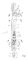
- the reference number 1 indicates a fuel injector as a whole, which fuel injector is housed in a cylindrical body 2 having a longitudinal axis 3 and is capable of being controlled for injecting fuel by an injection nozzle 4 regulated by an injection valve 5.
- an injection chamber 6 is produced, which is delimited below by a valve seat 7 of the injection valve 5 and houses, in a sliding manner, a lower portion of a pin 8 of the injection valve 5, in such a way that the pin 8 can be displaced along the longitudinal axis 3 when pushed by a hydraulic actuator device 9 between a position where the valve seat 7 is closed and a position where it is open; the lower portion of the pin 8 housed in the injection chamber 6 has a component 10 in the shape of a truncated cone, which reduces the section of said pin 8.
- an upper portion of the pin 8 is housed in a control chamber 11 and is coupled to a spring 12 that exerts on said pin 8 a downward force that tends to hold said pin 8 in the aforementioned closed position.
- the upper portion of the pin 8 has a tapered shape with a further change in section, which produces a surface 13 in the shape of a circular crown, from the centre of which there rises a cylindrical body 14 having the function of limiting the upward travel of the pin 8 against an upper surface of the control chamber 11; the spring 12 is arranged coaxially with the cylindrical body 14 so as to be compressed between the surface 13 in the shape of a circular crown and the upper surface of the control chamber 11.
- the useful area AU1 of the pin 8 on which the pressure of the fuel acts in order to determine a thrust along the longitudinal axis 3 is relatively small and is substantially equal to the sum of the area generated by the change in the section of the pin 8 in correspondence with the component 10 in the shape of a truncated cone and the area of the tip of the pin 8 not coupled to the valve seat 7 and immersed in the fuel; in contrast, in the control chamber 11 the useful area AU2 of the pin 8 on which the pressure of the fuel acts in order to determine a thrust along the longitudinal axis 3 is equal to the entire section of the pin 8 and is therefore greater than the useful area AU1 of the pin 8 in the injection chamber 6.
- the cylindrical body 2 also has a supply line 15, which starts from an upper end of the cylindrical body 2 and is capable of feeding the pressurised fuel to the injection chamber 6; from the supply line 15 another supply line 16 branches off, which is capable of putting the supply line 15 in communication with the control chamber 11 in order to supply pressurised fuel also to the control chamber 11.
- a drainage duct 17 leaves, capable of putting the control chamber 11 in communication with a drain 18, which is arranged in an upper portion of the cylindrical body 2 and finishes in a fuel collection and recirculation environment substantially at ambient pressure (not illustrated); the drainage duct 17 is regulated by a control valve 19, which is arranged close to the control chamber 11 and is controlled between a closed position, in which the control chamber 11 is isolated from the drainage duct 17, and an open position, in which the control chamber 11 is connected to the drainage duct 17.
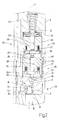
- the control valve 19 comprises a valve seat 20 produced along the drainage duct 17 and a valve body 21, which has a spherical shape and is moveable in a direction parallel to the longitudinal axis 3 from an engaged position (corresponding to the control valve 19 being closed) and a disengaged position (corresponding to the control valve 19 being open) of the valve seat 20 when being pushed by an electromagnetic actuator device 22 against the action of a spring 23 that tends to keep the valve body 21 in the engaged position.
- the control valve 19 is entirely housed along the drainage duct 17, which, for this reason, has a cylindrical chamber 24 in order to accommodate the actuator device 22.
- the electromagnetic actuator device 22 comprises two electromagnets 25, which are identical to each other, are electrically independent of each other and are both mechanically connected to the valve body 21 of the control valve 19 in order to displace the valve body 21 from the engaged position to the disengaged position against the action of the spring 23.
- each electromagnet 25 comprises a magnetic nucleus 26 of toroid shape, which houses a respective coil 27 and has a central hole 28 in which a respective pin 29 is engaged; each pin 29 is mounted in a sliding manner inside the corresponding central hole 28 and is integral with a respective armature 30 made of ferromagnetic material, which is magnetically attracted to the magnetic nucleus 26 when the relative coil 27 is energised.
- the pin 29 of the lower electromagnet 25 on the one hand bears against the valve body 21 of the control valve 19 and on the other hand bears against the pin 29 of the upper electromagnet 25; the pin 29 of the upper electromagnet 25 on the one hand bears against the pin 29 of the lower electromagnet 25 and on the other hand bears against one end of the spring 23 by the interposition of a cup-type connection component 31.
- the pin 29 of the lower electromagnet 25 bears against and is not fixed to the valve body 21 of the control valve 19 so as to define an articulation capable of making up for any errors of alignment; moreover, it should be noted that the valve body 21 and the pins 29 are held together by the opposing forces of pressure exerted by the fuel on the valve body 21 and by the spring 23.
- the magnetic nuclei 26 of the electromagnets 25 are held in position by a pair of annular positioning components 32 and by at least one Belleville spring 33 that is compressed between an upper wall of the chamber 24 and a base surface of the magnetic nucleus 26 of the upper electromagnet 25; in particular, a positioning component 32 is arranged between the magnetic nuclei 26 of the two electromagnets 25, and the other positioning component 32 is arranged between a base surface of the magnetic nucleus 26 of the lower electromagnet 25 and a lower wall of the chamber 24. It should be noted that the positioning components 32 also perform the function of recording the travel of the armatures 30.
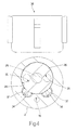
- the drainage duct 17 comprises two channels 34, which are parallel to the longitudinal axis 3 of the injector 1 and extend from the chamber 24 to the drain 18; each channel 34 has a semicircular section in correspondence with the chamber 24 and has a circular section between the chamber 24 and the drain 18.
- the armatures 30 of the two electromagnets 25 have a respective pair of through-holes 35 (illustrated in Figure 4) in order to control the permeability of said armatures 30 during their displacement.
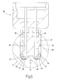
- channels 34 of the drainage duct 17 are to allow the passage of a flow of fuel through the chamber 24 to the drain 18; moreover, inside each channel 34, a pair of electrical conductors 36 is housed, supplying the coil 27 of a respective electromagnet 25. Obviously, inside each channel 34 the two electrical conductors 36 are insulated from one another and are isolated from the fuel by the interposition of a respective insulating component 37. Each pair of electrical conductors 36 extends between the respective coil 27 and an electrical connector 38, which is arranged in the upper portion of the cylindrical body 2 immediately below the drain 18.
- the electrical connector 38 is capable of being inserted, sealed off from the fuel, inside a respective hole 39 perpendicular to the longitudinal axis 3 of the injector 1; in particular, the electrical connector 38 comprises a pair of electrical contacts 40, which extend along the whole electrical connector 38 and on one side they bear against the electrical conductors 36 and on the opposite side they are free in the air and can be coupled with a female electrical connector (not illustrated) supplying the injector 1.
- the electrical contacts 40 are shaped so as to connect the two coils 27 together in series or parallel; for example, where the two coils 27 are connected in parallel, each electrical contact 40 bears against an electrical conductor 38 of one coil 27 and against an electrical conductor 38 of the other coil 27.
- the hole 39 housing the electrical connector 38 forms an angle other than 90° with the longitudinal axis 3 of the injector 1; for example, the hole 39, and therefore the electrical connector 38, could form an angle of 45° with the longitudinal axis 3 of the injector 1.
- the electrical connector 38 is blocked inside the hole 39 by a retaining trip device (known and not illustrated) or by another similar retaining device.
- the section of the supply line 16, the section of the control valve 19 and the section of the drainage duct 17 are given dimensions relative to the section of the supply line 15 so as to ensure that when the control valve 19 is open the pressure of the fuel in the control chamber 11 falls to much lower values than the pressure of the fuel in the injection chamber 6 and in order to ensure that the flow rate of fuel through the drainage duct 17 is a substantially negligible fraction of the flow rate of fuel through the injection nozzle 4.
- the force generated by the spring 23 holds the control valve 19 in the closed position; therefore, the pressure of the fuel in the control chamber 11 is the same as the pressure of the fuel in the injection chamber 6 through the effect of the supply line 16.
- the force generated by the spring 12, and the hydraulic force generated by the imbalance between the useful areas AU1 and AU2 of the pin 8, to the advantage of the control chamber 11, and the injection chamber 6, keep the injection valve 5 in the aforementioned closed position.
- the control valve 19 When the electromagnets 25 are energised by means of circulating electrical current, the control valve 19 is moved to the open position as described above, therefore the control chamber 11 is put into communication with the drain 18 and the pressure of the fuel in the control chamber 11 falls to much lower values than the pressure of the fuel in the injection chamber 6; as stated previously, the difference between the pressures of the fuel in the injection chamber 6 and the control chamber 11 is due to the dimensions of the sections of the supply line 16, the control valve 19 and the drainage duct 17 in comparison with the section of the supply line 15.
- the force generated by the spring 23 returns the control valve 19 to the closed position; therefore, the pressure of the fuel in the control chamber 11 tends to rise until it reaches the pressure of the fuel in the injection chamber 6.
- the force generated by the spring 12, and the hydraulic force generated by the imbalance between the useful areas AU1 and AU2 of the pin 8, to the advantage of the control chamber 11, and the injection chamber 6, return the injection valve 5 to the aforementioned closed position.
- the supply line 15 has a throat 43, which is arranged downstream of where the supply line 16 branches off, and is capable of instantaneously increasing the difference in pressure between the control chamber 11 and the injection chamber 6 during the transitory moment when the pin 8 closes (when the pin passes from the position where the valve seat 7 is open to the position where it is closed) in order to increase the force acting on the pin 8 and, therefore, to speed up the closing of said pin 8.
- more than two electromagnets 25, connected mechanically in series are used according to the method described above; by way of example, three or four electromagnets 25 connected mechanically in series could be used.
- three or four electromagnets 25 connected mechanically in series could be used.
- such an embodiment is used when it is necessary for the electromagnetic actuator 22 to be capable of generating a very great force.
- the two electromagnets 25 are perfectly identical to each other and that, for each electromagnet 25, the respective armature 30 is guided by the corresponding pin 29. This detail proves to be important, since it allows each armature 30 to be coupled with its own magnetic nucleus 26 before inserting said armature 30 inside the injector 1; in this way, any error made in the dimensions of the relative air gap is reduced.
Abstract
Description
- The present invention relates to a fuel injector with hydraulic pin actuation.
- Fuel injectors with electromagnetic pin actuation are commercially available, and they differ greatly in how they combine good performance and modest cost. An injector with electromagnetic pin actuation is provided with an valve injection having a valve seat, which ends in an injection nozzle and is coupled with a pin capable of being displaced from a position where the valve seat is closed to a position where the valve seat is open by a thrust by an electromagnetic actuator and against the action of a spring capable of holding the pin in the closed position; in particular, the actuator comprises an electromagnet capable of displacing the pin from the closed position to the open position against the action of the spring.
- Injectors with electromagnetic pin actuation work very well with low to medium fuel pressures, while critical situations can arise with high fuel pressures since the electromagnet may not be able to produce sufficient force to open the injector in short periods of time; for this reason, injectors with hydraulic pin actuation have been proposed, i.e. injectors in which the displacement of the pin from the closed position to the open position against the action of the spring happens through the effect of hydraulic forces.
- An example of an injector with hydraulic pin actuation is provided by patent application
EP-1036932-A2 or patent applicationEP-0921302-A2 , in which a lower portion of the pin is housed in an injection chamber, which is delimited below by the valve seat of the injection valve, and an upper portion of the pin is housed in a control chamber, which houses the spring that keeps the pin in the closed position; fuel is fed constantly at pressure either to the injection chamber, which it leaves through the injection nozzle when the pin is in the open position, or to the control chamber. The control chamber is coupled to a control valve, which is actuated by an electromagnetic actuator so as to be displaced against the action of a control spring between a closed position and an open position, in which it puts the control chamber in communication with a low-pressure drainage environment. In use, when the control valve is closed, the pressure of the fuel in the control chamber is equal to the pressure of the fuel in the injection chamber, and the pin is held in the closed position either by the action of the spring or by the hydraulic force that is generated when the area of the pin subject to the action of the fuel is greater in the upper portion housed in the control chamber than in the lower portion housed in the injection chamber. When the control valve is open, the pressure of the fuel in the control chamber falls to much lower values than the pressure of the fuel in the injection chamber and the pin is displaced upwards into the open position by the effect of the hydraulic force that is generated by the difference in pressure. - Another example of an injector with hydraulic pin actuation is provided by patent application
WO-0129395-A1 - Patents
US-5664545-A1 ,DE-1016484-A ,EP-0851115-A1 andEP-0999360-A1 supply further examples of injectors with hydraulic pin actuation. - The operation of the control spring is to hold the valve body of the control valve in the closed position with a predetermined elastic force that must be greater than the hydraulic force exerted by the fuel; clearly, the greater the working pressure of the fuel, the greater the elastic force that has to be exerted by the spring. As the working pressure of the fuel has gradually risen, higher-performance control springs are being used, capable of exerting ever-higher elastic forces; obviously, an increase in the elastic force exerted by the control spring that holds the valve body of the control valve in the closed position involves a corresponding increase in the force that has to be generated by the electromagnetic actuator of the control valve in order to move the control valve from the closed position to the open position. However, in known injectors with hydraulic pin actuation the increase in the force generated by the electromagnetic actuator of the control valve has proved problematic and has only been resolved by increasing the transverse dimension of the injectors.
- As described by patent application
IT-BO2002A000497 IT-B02002A 000497 -
GB2341893 - The aim of the present invention is to produce a fuel injector with hydraulic pin actuation that has none of the disadvantages described above and, in particular, is easy and economic to actuate.
- According to the present invention, a fuel injector with hydraulic pin actuation is produced as claimed in the attached claims.
- The present invention will now be described with reference to the attached drawings, which illustrate a non-limiting embodiment thereof, in which:
- Figure 1 is a schematic view, from the side and in cross section, of a fuel injector produced according to the present invention;
- Figure 2 is a view on an enlarged scale of a detail in Figure 1;
- Figure 3 is a view on an enlarged scale of a further detail in Figure 1;
- Figure 4 is a view on an enlarged scale and in cross section along the line IV-IV of the injector in Figure 1;
- Figure 5 is a view on an enlarged scale and in cross section along the line V-V of the injector in Figure 1; and
- Figure 6 is a view on an enlarged scale and in section along the line VI-VI of the injector in Figure 1.
- In Figure 1 the
reference number 1 indicates a fuel injector as a whole, which fuel injector is housed in acylindrical body 2 having alongitudinal axis 3 and is capable of being controlled for injecting fuel by an injection nozzle 4 regulated by aninjection valve 5. Inside thecylindrical body 2 aninjection chamber 6 is produced, which is delimited below by avalve seat 7 of theinjection valve 5 and houses, in a sliding manner, a lower portion of apin 8 of theinjection valve 5, in such a way that thepin 8 can be displaced along thelongitudinal axis 3 when pushed by ahydraulic actuator device 9 between a position where thevalve seat 7 is closed and a position where it is open; the lower portion of thepin 8 housed in theinjection chamber 6 has acomponent 10 in the shape of a truncated cone, which reduces the section of saidpin 8. - As illustrated in Figure 2, an upper portion of the
pin 8 is housed in acontrol chamber 11 and is coupled to aspring 12 that exerts on said pin 8 a downward force that tends to hold saidpin 8 in the aforementioned closed position. In particular, the upper portion of thepin 8 has a tapered shape with a further change in section, which produces asurface 13 in the shape of a circular crown, from the centre of which there rises acylindrical body 14 having the function of limiting the upward travel of thepin 8 against an upper surface of thecontrol chamber 11; thespring 12 is arranged coaxially with thecylindrical body 14 so as to be compressed between thesurface 13 in the shape of a circular crown and the upper surface of thecontrol chamber 11. - It should be noted that in the
injection chamber 6 the useful area AU1 of thepin 8 on which the pressure of the fuel acts in order to determine a thrust along thelongitudinal axis 3 is relatively small and is substantially equal to the sum of the area generated by the change in the section of thepin 8 in correspondence with thecomponent 10 in the shape of a truncated cone and the area of the tip of thepin 8 not coupled to thevalve seat 7 and immersed in the fuel; in contrast, in thecontrol chamber 11 the useful area AU2 of thepin 8 on which the pressure of the fuel acts in order to determine a thrust along thelongitudinal axis 3 is equal to the entire section of thepin 8 and is therefore greater than the useful area AU1 of thepin 8 in theinjection chamber 6. - The
cylindrical body 2 also has asupply line 15, which starts from an upper end of thecylindrical body 2 and is capable of feeding the pressurised fuel to theinjection chamber 6; from thesupply line 15 anothersupply line 16 branches off, which is capable of putting thesupply line 15 in communication with thecontrol chamber 11 in order to supply pressurised fuel also to thecontrol chamber 11. - From the control chamber 11 a
drainage duct 17 leaves, capable of putting thecontrol chamber 11 in communication with adrain 18, which is arranged in an upper portion of thecylindrical body 2 and finishes in a fuel collection and recirculation environment substantially at ambient pressure (not illustrated); thedrainage duct 17 is regulated by acontrol valve 19, which is arranged close to thecontrol chamber 11 and is controlled between a closed position, in which thecontrol chamber 11 is isolated from thedrainage duct 17, and an open position, in which thecontrol chamber 11 is connected to thedrainage duct 17. - The
control valve 19 comprises avalve seat 20 produced along thedrainage duct 17 and avalve body 21, which has a spherical shape and is moveable in a direction parallel to thelongitudinal axis 3 from an engaged position (corresponding to thecontrol valve 19 being closed) and a disengaged position (corresponding to thecontrol valve 19 being open) of thevalve seat 20 when being pushed by anelectromagnetic actuator device 22 against the action of aspring 23 that tends to keep thevalve body 21 in the engaged position. Thecontrol valve 19 is entirely housed along thedrainage duct 17, which, for this reason, has acylindrical chamber 24 in order to accommodate theactuator device 22. - The
electromagnetic actuator device 22 comprises twoelectromagnets 25, which are identical to each other, are electrically independent of each other and are both mechanically connected to thevalve body 21 of thecontrol valve 19 in order to displace thevalve body 21 from the engaged position to the disengaged position against the action of thespring 23. In particular, eachelectromagnet 25 comprises amagnetic nucleus 26 of toroid shape, which houses arespective coil 27 and has acentral hole 28 in which arespective pin 29 is engaged; eachpin 29 is mounted in a sliding manner inside the correspondingcentral hole 28 and is integral with arespective armature 30 made of ferromagnetic material, which is magnetically attracted to themagnetic nucleus 26 when therelative coil 27 is energised. - The
pin 29 of thelower electromagnet 25 on the one hand bears against thevalve body 21 of thecontrol valve 19 and on the other hand bears against thepin 29 of theupper electromagnet 25; thepin 29 of theupper electromagnet 25 on the one hand bears against thepin 29 of thelower electromagnet 25 and on the other hand bears against one end of thespring 23 by the interposition of a cup-type connection component 31. It is important to note that thepin 29 of thelower electromagnet 25 bears against and is not fixed to thevalve body 21 of thecontrol valve 19 so as to define an articulation capable of making up for any errors of alignment; moreover, it should be noted that thevalve body 21 and thepins 29 are held together by the opposing forces of pressure exerted by the fuel on thevalve body 21 and by thespring 23. - Inside the
chamber 24, themagnetic nuclei 26 of theelectromagnets 25 are held in position by a pair ofannular positioning components 32 and by at least one Bellevillespring 33 that is compressed between an upper wall of thechamber 24 and a base surface of themagnetic nucleus 26 of theupper electromagnet 25; in particular, apositioning component 32 is arranged between themagnetic nuclei 26 of the twoelectromagnets 25, and theother positioning component 32 is arranged between a base surface of themagnetic nucleus 26 of thelower electromagnet 25 and a lower wall of thechamber 24. It should be noted that thepositioning components 32 also perform the function of recording the travel of thearmatures 30. - It is clear from the above that the two
electromagnets 25 are stacked on top of one another and are arranged mechanically in series with each other so that the respective thrust forces are added together. - As illustrated in Figures 4, 5 and 6, the
drainage duct 17 comprises twochannels 34, which are parallel to thelongitudinal axis 3 of theinjector 1 and extend from thechamber 24 to thedrain 18; eachchannel 34 has a semicircular section in correspondence with thechamber 24 and has a circular section between thechamber 24 and thedrain 18. Thearmatures 30 of the twoelectromagnets 25 have a respective pair of through-holes 35 (illustrated in Figure 4) in order to control the permeability of saidarmatures 30 during their displacement. - One purpose of the
channels 34 of thedrainage duct 17 is to allow the passage of a flow of fuel through thechamber 24 to thedrain 18; moreover, inside eachchannel 34, a pair ofelectrical conductors 36 is housed, supplying thecoil 27 of arespective electromagnet 25. Obviously, inside eachchannel 34 the twoelectrical conductors 36 are insulated from one another and are isolated from the fuel by the interposition of arespective insulating component 37. Each pair ofelectrical conductors 36 extends between therespective coil 27 and anelectrical connector 38, which is arranged in the upper portion of thecylindrical body 2 immediately below thedrain 18. - As illustrated in Figures 3 and 6 the
electrical connector 38 is capable of being inserted, sealed off from the fuel, inside arespective hole 39 perpendicular to thelongitudinal axis 3 of theinjector 1; in particular, theelectrical connector 38 comprises a pair ofelectrical contacts 40, which extend along the wholeelectrical connector 38 and on one side they bear against theelectrical conductors 36 and on the opposite side they are free in the air and can be coupled with a female electrical connector (not illustrated) supplying theinjector 1. It should be noted that theelectrical contacts 40 are shaped so as to connect the twocoils 27 together in series or parallel; for example, where the twocoils 27 are connected in parallel, eachelectrical contact 40 bears against anelectrical conductor 38 of onecoil 27 and against anelectrical conductor 38 of theother coil 27. In another embodiment, thehole 39 housing theelectrical connector 38 forms an angle other than 90° with thelongitudinal axis 3 of theinjector 1; for example, thehole 39, and therefore theelectrical connector 38, could form an angle of 45° with thelongitudinal axis 3 of theinjector 1. - In order to ensure that the fuel is sealed off from the
electrical connector 38, there is anelastic sealing ring 41 between theelectrical connector 38 and thehole 39, and there is anelastic sealing ring 42 around eachelectrical contact 40. Preferably, theelectrical connector 38 is blocked inside thehole 39 by a retaining trip device (known and not illustrated) or by another similar retaining device. - The section of the
supply line 16, the section of thecontrol valve 19 and the section of thedrainage duct 17 are given dimensions relative to the section of thesupply line 15 so as to ensure that when thecontrol valve 19 is open the pressure of the fuel in thecontrol chamber 11 falls to much lower values than the pressure of the fuel in theinjection chamber 6 and in order to ensure that the flow rate of fuel through thedrainage duct 17 is a substantially negligible fraction of the flow rate of fuel through the injection nozzle 4. - In use, when the
electromagnets 25 are de-energised, the force generated by thespring 23 holds thecontrol valve 19 in the closed position; therefore, the pressure of the fuel in thecontrol chamber 11 is the same as the pressure of the fuel in theinjection chamber 6 through the effect of thesupply line 16. In this situation, the force generated by thespring 12, and the hydraulic force generated by the imbalance between the useful areas AU1 and AU2 of thepin 8, to the advantage of thecontrol chamber 11, and theinjection chamber 6, keep theinjection valve 5 in the aforementioned closed position. - When the
electromagnets 25 are energised by means of circulating electrical current, thecontrol valve 19 is moved to the open position as described above, therefore thecontrol chamber 11 is put into communication with thedrain 18 and the pressure of the fuel in thecontrol chamber 11 falls to much lower values than the pressure of the fuel in theinjection chamber 6; as stated previously, the difference between the pressures of the fuel in theinjection chamber 6 and thecontrol chamber 11 is due to the dimensions of the sections of thesupply line 16, thecontrol valve 19 and thedrainage duct 17 in comparison with the section of thesupply line 15. - Through the effect of the imbalance between the pressures of the fuel in the
injection chamber 6 and thecontrol chamber 11, a hydraulic force is generated on thepin 8, which force is capable of displacing thepin 8 upwards against the action of thespring 12 so as to move theinjection valve 5 to the aforementioned open position and to allow the injection of the fuel through the injection nozzle 4. - When the
electromagnets 25 are de-energised, the force generated by thespring 23 returns thecontrol valve 19 to the closed position; therefore, the pressure of the fuel in thecontrol chamber 11 tends to rise until it reaches the pressure of the fuel in theinjection chamber 6. In this situation, the force generated by thespring 12, and the hydraulic force generated by the imbalance between the useful areas AU1 and AU2 of thepin 8, to the advantage of thecontrol chamber 11, and theinjection chamber 6, return theinjection valve 5 to the aforementioned closed position. - Preferably, the
supply line 15 has athroat 43, which is arranged downstream of where thesupply line 16 branches off, and is capable of instantaneously increasing the difference in pressure between thecontrol chamber 11 and theinjection chamber 6 during the transitory moment when thepin 8 closes (when the pin passes from the position where thevalve seat 7 is open to the position where it is closed) in order to increase the force acting on thepin 8 and, therefore, to speed up the closing of saidpin 8. - According to another embodiment not illustrated, more than two
electromagnets 25, connected mechanically in series, are used according to the method described above; by way of example, three or fourelectromagnets 25 connected mechanically in series could be used. Obviously, such an embodiment is used when it is necessary for theelectromagnetic actuator 22 to be capable of generating a very great force. - Experimental tests have demonstrated that the
injector 1 described above has optimal dynamic characteristics, even when operating with very high fuel pressures, and it proves economical, compact and easy to produce. Any error in the size of the air gap of thearmatures 30 is reduced to a minimum, consequently limiting the structural dispersions of theinjector 1. Finally, through the configuration described above, a reduction of the total mass of the moveable part is obtained with beneficial effects in reducing the phenomenon of bounce in thecontrol valve 19; in this way, the metering of the fuel is always very accurate and in particular a series of pilot fuel preinjections can be performed accurately and in rapid sequence, marked by a very short injection time. - It should be noted that the two
electromagnets 25 are perfectly identical to each other and that, for eachelectromagnet 25, therespective armature 30 is guided by the correspondingpin 29. This detail proves to be important, since it allows eacharmature 30 to be coupled with its ownmagnetic nucleus 26 before inserting saidarmature 30 inside theinjector 1; in this way, any error made in the dimensions of the relative air gap is reduced.
Claims (9)
- Fuel injector (1) comprising:a cylindrical body (2), which houses an injection nozzle (4) regulated by an injection valve (5) provided with a moveable pin (8);a first fuel supply line (15);an injection chamber (6) communicating with the first supply line (15), housing a lower portion of the pin (8) and delimited below by a valve seat (7) of the injection valve (5);a control chamber (11) communicating with the first supply line (15) and housing an upper portion of the pin (8); anda control valve (19), which is actuated by an electromagnetic actuator (22) in order to be displaced from an open position, in which it puts the control chamber (11) in communication with a drain (18) for the fuel at low pressure, against the action of a first spring (23); wherein the electromagnetic actuator (22) comprises at least two electromagnets (25), which are identical to each other, are stacked on top of each other and are arranged mechanically in series with each other so that the respective thrust forces are added together;the injector (1) being characterised by the fact that a drainage channel (17) is provided, which channel is capable of putting the control chamber (11) in communication with the drain (18), is regulated by the control valve (19) and comprises two channels (34) that extend as far as the drain (18); inside each channel (34), a pair of electrical conductors (36) being housed, supplying a respective electromagnet (25).
- Injector according to Claim 1, wherein, inside each channel (34), the two electrical conductors (36) are insulated from each other by the interposition of a respective insulating component (37).
- Injector according to Claim 1 or 2, comprising an electrical connector (38) capable of being inserted, sealed off from the fuel, inside a respective hole (39); each pair of electrical conductors (36) extending between the respective electromagnet (25) and the electrical connector (38).
- Injector according to Claim 3, wherein the electrical connector (38) forms an angle of 90° with a longitudinal axis (3) of the injector (1).
- Injector according to Claim 3, wherein the electrical connector (38) forms an angle other than 90° with a longitudinal axis (3) of the injector (1).
- Injector according to Claim 5, wherein the electrical connector (38) forms an angle of 45° with the longitudinal axis (3) of the injector (1).
- Injector according to one of Claims 3 to 6, wherein the electrical connector (38) comprises a pair of electrical contacts (40), which extend along the whole electrical connector (38) and on one side bear against the electrical conductors (36) and on the opposite side are free in the air and can be coupled with a female electrical connector supplying the injector (1).
- Injector according to Claim 7, wherein the electrical contacts (40) are shaped so as to connect together the two electromagnets (25) in series or in parallel.
- Injector according to Claim 7 or 8, wherein there is a first elastic sealing ring (41) between the electrical connector (38) and the hole (39), and there is a second elastic sealing ring (42) around each electrical contact (40).
Applications Claiming Priority (2)
| Application Number | Priority Date | Filing Date | Title |
|---|---|---|---|
| IT000678A ITBO20030678A1 (en) | 2003-11-14 | 2003-11-14 | FUEL INJECTOR WITH HYDRAULIC IMPLEMENTATION OF THE PIN |
| EP04105723A EP1533517A3 (en) | 2003-11-14 | 2004-11-12 | Fuel injector with hydraulic pin actuation |
Related Parent Applications (2)
| Application Number | Title | Priority Date | Filing Date |
|---|---|---|---|
| EP04105723A Division EP1533517A3 (en) | 2003-11-14 | 2004-11-12 | Fuel injector with hydraulic pin actuation |
| EP04105723.3 Division | 2004-11-12 |
Publications (3)
| Publication Number | Publication Date |
|---|---|
| EP1775458A2 true EP1775458A2 (en) | 2007-04-18 |
| EP1775458A3 EP1775458A3 (en) | 2007-10-17 |
| EP1775458B1 EP1775458B1 (en) | 2010-11-10 |
Family
ID=34430714
Family Applications (2)
| Application Number | Title | Priority Date | Filing Date |
|---|---|---|---|
| EP04105723A Withdrawn EP1533517A3 (en) | 2003-11-14 | 2004-11-12 | Fuel injector with hydraulic pin actuation |
| EP07101238A Not-in-force EP1775458B1 (en) | 2003-11-14 | 2004-11-12 | Fuel injector with hydraulic pin actuation |
Family Applications Before (1)
| Application Number | Title | Priority Date | Filing Date |
|---|---|---|---|
| EP04105723A Withdrawn EP1533517A3 (en) | 2003-11-14 | 2004-11-12 | Fuel injector with hydraulic pin actuation |
Country Status (7)
| Country | Link |
|---|---|
| US (1) | US7191963B2 (en) |
| EP (2) | EP1533517A3 (en) |
| CN (2) | CN1619136A (en) |
| AT (1) | ATE487876T1 (en) |
| BR (1) | BRPI0404968B1 (en) |
| DE (1) | DE602004030050D1 (en) |
| IT (1) | ITBO20030678A1 (en) |
Families Citing this family (15)
| Publication number | Priority date | Publication date | Assignee | Title |
|---|---|---|---|---|
| DE102004046888A1 (en) * | 2004-09-28 | 2006-03-30 | Robert Bosch Gmbh | Injector for fuel injection on an internal combustion engine |
| DE102006000323B4 (en) | 2005-07-07 | 2022-09-15 | Denso Corporation | Electric actuator and manufacturing method therefor |
| JP4483828B2 (en) * | 2005-09-15 | 2010-06-16 | 株式会社デンソー | Fuel injection valve |
| US7658631B2 (en) * | 2007-06-25 | 2010-02-09 | Caterpillar Inc. | Four wire elastomeric seal and fuel injector using same |
| JP5267907B2 (en) * | 2007-12-28 | 2013-08-21 | 国立大学法人九州工業大学 | Actuator using magnetic force, driving device using the same, and sensor |
| CN101251067B (en) * | 2008-03-21 | 2010-06-02 | 北京理工大学 | Tappet rod type high pressure co-rail electric-controlled oil ejector |
| US20100044471A1 (en) * | 2008-08-22 | 2010-02-25 | Bircann Raul A | Fuel injector with energy adsorbing pole |
| DE102009003219A1 (en) * | 2009-05-19 | 2010-11-25 | Robert Bosch Gmbh | Active closing solenoid valve for magnetic injectors |
| HUE025828T2 (en) * | 2010-10-20 | 2016-05-30 | Delphi Int Operations Luxembourg Sarl | Improved fuel injector |
| WO2013028561A1 (en) * | 2011-08-19 | 2013-02-28 | Woodward, Inc. | Staged cooling flow nozzle valve |
| DE102012220610B4 (en) * | 2012-11-13 | 2015-04-02 | Continental Automotive Gmbh | injector |
| JP6080087B2 (en) * | 2014-02-28 | 2017-02-15 | 株式会社デンソー | Fuel injection valve |
| GB201408060D0 (en) * | 2014-05-07 | 2014-06-18 | Delphi Int Operations Lux Srl | Connector assembly for a fuel injector |
| FR3038662B1 (en) * | 2015-07-09 | 2019-08-09 | Delphi Technologies Ip Limited | FUEL INJECTOR WITH EXTERNAL SPRING SPRING SPRING |
| DE102016220912A1 (en) * | 2016-10-25 | 2018-04-26 | Robert Bosch Gmbh | Fuel injection valve |
Citations (7)
| Publication number | Priority date | Publication date | Assignee | Title |
|---|---|---|---|---|
| EP0331200A2 (en) * | 1988-03-04 | 1989-09-06 | Yamaha Motor Co., Ltd. | Fuel injection nozzle |
| GB2339077A (en) * | 1998-07-13 | 2000-01-12 | Caterpillar Inc | Device with two solenoids controlled by a single circuit |
| GB2341893A (en) * | 1998-09-23 | 2000-03-29 | Lucas Industries Ltd | Two-stage electromagnetically actuated fuel injector for i.c. engines |
| US6065684A (en) * | 1998-03-27 | 2000-05-23 | General Motors Corporation | Fuel injector and method |
| EP1130249A2 (en) * | 2000-02-29 | 2001-09-05 | Rodi Power Systems, Inc. | Magnetostrictively actuated fuel injector |
| EP1193391A1 (en) * | 2000-09-28 | 2002-04-03 | Denso Corporation | Coil system including a structure for preventing fluid from leaking therein |
| DE10206908A1 (en) * | 2002-02-19 | 2003-09-04 | Siemens Ag | Injector with improved connection geometry |
Family Cites Families (9)
| Publication number | Priority date | Publication date | Assignee | Title |
|---|---|---|---|---|
| US4033513A (en) | 1975-11-06 | 1977-07-05 | Allied Chemical Corporation | Electromagnetically operated valve |
| JPH01224454A (en) * | 1988-03-04 | 1989-09-07 | Yamaha Motor Co Ltd | High pressure fuel injection device of engine |
| JPH02218859A (en) * | 1989-02-20 | 1990-08-31 | Yamaha Motor Co Ltd | High pressure fuel injection device for engine |
| US5494219A (en) | 1994-06-02 | 1996-02-27 | Caterpillar Inc. | Fuel injection control valve with dual solenoids |
| JPH11148439A (en) | 1997-06-26 | 1999-06-02 | Hitachi Ltd | Electromagnetic fuel injection valve and its fuel injection method |
| JP2000018119A (en) | 1998-06-30 | 2000-01-18 | Isuzu Motors Ltd | Fuel injection system |
| GB2341839B (en) | 1998-09-25 | 2002-08-14 | Caterpillar Inc | Overhead rail for an ejector type work machine |
| DE10001099A1 (en) * | 2000-01-13 | 2001-08-02 | Bosch Gmbh Robert | Control valve for injector of fuel injection system for internal combustion engine; has regulator connected to pressure piston to separate control chamber from control valve and increase pressure |
| ITBO20020497A1 (en) | 2002-07-30 | 2004-01-30 | Magneti Marelli Powertrain Spa | FUEL INJECTOR FOR AN INTERNAL COMBUSTION ENGINE WITH HYDRAULIC PIN ACTUATION |
-
2003
- 2003-11-14 IT IT000678A patent/ITBO20030678A1/en unknown
-
2004
- 2004-11-09 US US10/983,905 patent/US7191963B2/en not_active Expired - Fee Related
- 2004-11-12 EP EP04105723A patent/EP1533517A3/en not_active Withdrawn
- 2004-11-12 DE DE602004030050T patent/DE602004030050D1/en active Active
- 2004-11-12 EP EP07101238A patent/EP1775458B1/en not_active Not-in-force
- 2004-11-12 AT AT07101238T patent/ATE487876T1/en not_active IP Right Cessation
- 2004-11-15 CN CN200410092652.9A patent/CN1619136A/en active Pending
- 2004-11-15 CN CN200810144031.9A patent/CN101403360B/en not_active Expired - Fee Related
- 2004-11-16 BR BRPI0404968A patent/BRPI0404968B1/en not_active IP Right Cessation
Patent Citations (7)
| Publication number | Priority date | Publication date | Assignee | Title |
|---|---|---|---|---|
| EP0331200A2 (en) * | 1988-03-04 | 1989-09-06 | Yamaha Motor Co., Ltd. | Fuel injection nozzle |
| US6065684A (en) * | 1998-03-27 | 2000-05-23 | General Motors Corporation | Fuel injector and method |
| GB2339077A (en) * | 1998-07-13 | 2000-01-12 | Caterpillar Inc | Device with two solenoids controlled by a single circuit |
| GB2341893A (en) * | 1998-09-23 | 2000-03-29 | Lucas Industries Ltd | Two-stage electromagnetically actuated fuel injector for i.c. engines |
| EP1130249A2 (en) * | 2000-02-29 | 2001-09-05 | Rodi Power Systems, Inc. | Magnetostrictively actuated fuel injector |
| EP1193391A1 (en) * | 2000-09-28 | 2002-04-03 | Denso Corporation | Coil system including a structure for preventing fluid from leaking therein |
| DE10206908A1 (en) * | 2002-02-19 | 2003-09-04 | Siemens Ag | Injector with improved connection geometry |
Also Published As
| Publication number | Publication date |
|---|---|
| EP1533517A2 (en) | 2005-05-25 |
| EP1775458A3 (en) | 2007-10-17 |
| EP1775458B1 (en) | 2010-11-10 |
| ITBO20030678A1 (en) | 2005-05-15 |
| ATE487876T1 (en) | 2010-11-15 |
| EP1533517A3 (en) | 2006-02-01 |
| CN101403360B (en) | 2011-01-05 |
| CN101403360A (en) | 2009-04-08 |
| DE602004030050D1 (en) | 2010-12-23 |
| BRPI0404968B1 (en) | 2017-02-21 |
| US7191963B2 (en) | 2007-03-20 |
| CN1619136A (en) | 2005-05-25 |
| US20050103882A1 (en) | 2005-05-19 |
| BRPI0404968A (en) | 2005-07-19 |
Similar Documents
| Publication | Publication Date | Title |
|---|---|---|
| EP1775458B1 (en) | Fuel injector with hydraulic pin actuation | |
| EP1820958B1 (en) | Electro-magnetic fuel injector | |
| EP1852602B1 (en) | Electromagnetically actuated fuel injector | |
| US6279843B1 (en) | Single pole solenoid assembly and fuel injector using same | |
| US7422165B2 (en) | Fuel injector with electromagnetic actuation of the plunger | |
| EP2749800B1 (en) | Solenoid valve | |
| EP1734251A1 (en) | Fuel injector | |
| CN100417805C (en) | Fuel injector with an antirebound device | |
| EP1988278B1 (en) | Outward opening fuel injector | |
| CN101529081B (en) | Injector with an axial pressure-compensating control valve | |
| US5608368A (en) | Electromagnet for controlling the metering valve of a fuel injector | |
| CN103975157A (en) | Valve assembly for a control valve and control valve | |
| EP2971900B1 (en) | Apparatus for controlling the lift of a valve member | |
| EP2749799A1 (en) | Solenoid actuator | |
| EP2194543B1 (en) | Solenoid actuator | |
| EP1387077B1 (en) | Fuel injector for an internal combustion engine with hydraulic pin actuation | |
| EP2944797B1 (en) | Valve actuator of a fuel injector | |
| EP3109455A1 (en) | Fuel injection rate modulation by magnetostrictive actuator and fluidomechanical coupler | |
| WO2019163383A1 (en) | Fuel injection valve and method for assembling same | |
| CN115398092A (en) | Nozzle needle for a fuel injector and injector housing for a nozzle needle | |
| CN117795187A (en) | Fuel injector |
Legal Events
| Date | Code | Title | Description |
|---|---|---|---|
| PUAI | Public reference made under article 153(3) epc to a published international application that has entered the european phase |
Free format text: ORIGINAL CODE: 0009012 |
|
| AC | Divisional application: reference to earlier application |
Ref document number: 1533517 Country of ref document: EP Kind code of ref document: P |
|
| AK | Designated contracting states |
Kind code of ref document: A2 Designated state(s): AT BE BG CH CY CZ DE DK EE ES FI FR GB GR HU IE IS IT LI LU MC NL PL PT RO SE SI SK TR |
|
| PUAL | Search report despatched |
Free format text: ORIGINAL CODE: 0009013 |
|
| AK | Designated contracting states |
Kind code of ref document: A3 Designated state(s): AT BE BG CH CY CZ DE DK EE ES FI FR GB GR HU IE IS IT LI LU MC NL PL PT RO SE SI SK TR |
|
| RIC1 | Information provided on ipc code assigned before grant |
Ipc: F02M 47/02 20060101ALI20070907BHEP Ipc: F02M 59/46 20060101ALI20070907BHEP Ipc: F02M 51/06 20060101ALI20070907BHEP Ipc: F02M 63/00 20060101ALI20070907BHEP Ipc: F02M 51/00 20060101AFI20070222BHEP Ipc: F02M 55/00 20060101ALI20070907BHEP |
|
| 17P | Request for examination filed |
Effective date: 20071108 |
|
| AKX | Designation fees paid |
Designated state(s): AT BE BG CH CY CZ DE DK EE ES FI FR GB GR HU IE IS IT LI LU MC NL PL PT RO SE SI SK TR |
|
| GRAP | Despatch of communication of intention to grant a patent |
Free format text: ORIGINAL CODE: EPIDOSNIGR1 |
|
| RAP1 | Party data changed (applicant data changed or rights of an application transferred) |
Owner name: MAGNETI MARELLI S.P.A. |
|
| GRAS | Grant fee paid |
Free format text: ORIGINAL CODE: EPIDOSNIGR3 |
|
| GRAA | (expected) grant |
Free format text: ORIGINAL CODE: 0009210 |
|
| AC | Divisional application: reference to earlier application |
Ref document number: 1533517 Country of ref document: EP Kind code of ref document: P |
|
| AK | Designated contracting states |
Kind code of ref document: B1 Designated state(s): AT BE BG CH CY CZ DE DK EE ES FI FR GB GR HU IE IS IT LI LU MC NL PL PT RO SE SI SK TR |
|
| REG | Reference to a national code |
Ref country code: GB Ref legal event code: FG4D |
|
| REG | Reference to a national code |
Ref country code: CH Ref legal event code: EP |
|
| REG | Reference to a national code |
Ref country code: IE Ref legal event code: FG4D |
|
| REF | Corresponds to: |
Ref document number: 602004030050 Country of ref document: DE Date of ref document: 20101223 Kind code of ref document: P |
|
| REG | Reference to a national code |
Ref country code: NL Ref legal event code: VDEP Effective date: 20101110 |
|
| PG25 | Lapsed in a contracting state [announced via postgrant information from national office to epo] |
Ref country code: AT Free format text: LAPSE BECAUSE OF FAILURE TO SUBMIT A TRANSLATION OF THE DESCRIPTION OR TO PAY THE FEE WITHIN THE PRESCRIBED TIME-LIMIT Effective date: 20101110 Ref country code: PT Free format text: LAPSE BECAUSE OF FAILURE TO SUBMIT A TRANSLATION OF THE DESCRIPTION OR TO PAY THE FEE WITHIN THE PRESCRIBED TIME-LIMIT Effective date: 20110310 Ref country code: NL Free format text: LAPSE BECAUSE OF FAILURE TO SUBMIT A TRANSLATION OF THE DESCRIPTION OR TO PAY THE FEE WITHIN THE PRESCRIBED TIME-LIMIT Effective date: 20101110 Ref country code: BG Free format text: LAPSE BECAUSE OF FAILURE TO SUBMIT A TRANSLATION OF THE DESCRIPTION OR TO PAY THE FEE WITHIN THE PRESCRIBED TIME-LIMIT Effective date: 20110210 Ref country code: SI Free format text: LAPSE BECAUSE OF FAILURE TO SUBMIT A TRANSLATION OF THE DESCRIPTION OR TO PAY THE FEE WITHIN THE PRESCRIBED TIME-LIMIT Effective date: 20101110 Ref country code: IS Free format text: LAPSE BECAUSE OF FAILURE TO SUBMIT A TRANSLATION OF THE DESCRIPTION OR TO PAY THE FEE WITHIN THE PRESCRIBED TIME-LIMIT Effective date: 20110310 Ref country code: CY Free format text: LAPSE BECAUSE OF FAILURE TO SUBMIT A TRANSLATION OF THE DESCRIPTION OR TO PAY THE FEE WITHIN THE PRESCRIBED TIME-LIMIT Effective date: 20101110 Ref country code: FI Free format text: LAPSE BECAUSE OF FAILURE TO SUBMIT A TRANSLATION OF THE DESCRIPTION OR TO PAY THE FEE WITHIN THE PRESCRIBED TIME-LIMIT Effective date: 20101110 Ref country code: SE Free format text: LAPSE BECAUSE OF FAILURE TO SUBMIT A TRANSLATION OF THE DESCRIPTION OR TO PAY THE FEE WITHIN THE PRESCRIBED TIME-LIMIT Effective date: 20101110 |
|
| PG25 | Lapsed in a contracting state [announced via postgrant information from national office to epo] |
Ref country code: MC Free format text: LAPSE BECAUSE OF NON-PAYMENT OF DUE FEES Effective date: 20101130 Ref country code: GR Free format text: LAPSE BECAUSE OF FAILURE TO SUBMIT A TRANSLATION OF THE DESCRIPTION OR TO PAY THE FEE WITHIN THE PRESCRIBED TIME-LIMIT Effective date: 20110211 |
|
| REG | Reference to a national code |
Ref country code: CH Ref legal event code: PL |
|
| PG25 | Lapsed in a contracting state [announced via postgrant information from national office to epo] |
Ref country code: LI Free format text: LAPSE BECAUSE OF NON-PAYMENT OF DUE FEES Effective date: 20101130 Ref country code: BE Free format text: LAPSE BECAUSE OF FAILURE TO SUBMIT A TRANSLATION OF THE DESCRIPTION OR TO PAY THE FEE WITHIN THE PRESCRIBED TIME-LIMIT Effective date: 20101110 Ref country code: ES Free format text: LAPSE BECAUSE OF FAILURE TO SUBMIT A TRANSLATION OF THE DESCRIPTION OR TO PAY THE FEE WITHIN THE PRESCRIBED TIME-LIMIT Effective date: 20110221 Ref country code: EE Free format text: LAPSE BECAUSE OF FAILURE TO SUBMIT A TRANSLATION OF THE DESCRIPTION OR TO PAY THE FEE WITHIN THE PRESCRIBED TIME-LIMIT Effective date: 20101110 Ref country code: CH Free format text: LAPSE BECAUSE OF NON-PAYMENT OF DUE FEES Effective date: 20101130 Ref country code: CZ Free format text: LAPSE BECAUSE OF FAILURE TO SUBMIT A TRANSLATION OF THE DESCRIPTION OR TO PAY THE FEE WITHIN THE PRESCRIBED TIME-LIMIT Effective date: 20101110 |
|
| PG25 | Lapsed in a contracting state [announced via postgrant information from national office to epo] |
Ref country code: SK Free format text: LAPSE BECAUSE OF FAILURE TO SUBMIT A TRANSLATION OF THE DESCRIPTION OR TO PAY THE FEE WITHIN THE PRESCRIBED TIME-LIMIT Effective date: 20101110 Ref country code: RO Free format text: LAPSE BECAUSE OF FAILURE TO SUBMIT A TRANSLATION OF THE DESCRIPTION OR TO PAY THE FEE WITHIN THE PRESCRIBED TIME-LIMIT Effective date: 20101110 Ref country code: PL Free format text: LAPSE BECAUSE OF FAILURE TO SUBMIT A TRANSLATION OF THE DESCRIPTION OR TO PAY THE FEE WITHIN THE PRESCRIBED TIME-LIMIT Effective date: 20101110 Ref country code: DK Free format text: LAPSE BECAUSE OF FAILURE TO SUBMIT A TRANSLATION OF THE DESCRIPTION OR TO PAY THE FEE WITHIN THE PRESCRIBED TIME-LIMIT Effective date: 20101110 |
|
| PLBE | No opposition filed within time limit |
Free format text: ORIGINAL CODE: 0009261 |
|
| STAA | Information on the status of an ep patent application or granted ep patent |
Free format text: STATUS: NO OPPOSITION FILED WITHIN TIME LIMIT |
|
| 26N | No opposition filed |
Effective date: 20110811 |
|
| GBPC | Gb: european patent ceased through non-payment of renewal fee |
Effective date: 20110210 |
|
| PG25 | Lapsed in a contracting state [announced via postgrant information from national office to epo] |
Ref country code: IE Free format text: LAPSE BECAUSE OF NON-PAYMENT OF DUE FEES Effective date: 20101112 |
|
| REG | Reference to a national code |
Ref country code: DE Ref legal event code: R097 Ref document number: 602004030050 Country of ref document: DE Effective date: 20110811 |
|
| PG25 | Lapsed in a contracting state [announced via postgrant information from national office to epo] |
Ref country code: GB Free format text: LAPSE BECAUSE OF NON-PAYMENT OF DUE FEES Effective date: 20110210 |
|
| PG25 | Lapsed in a contracting state [announced via postgrant information from national office to epo] |
Ref country code: HU Free format text: LAPSE BECAUSE OF FAILURE TO SUBMIT A TRANSLATION OF THE DESCRIPTION OR TO PAY THE FEE WITHIN THE PRESCRIBED TIME-LIMIT Effective date: 20110511 Ref country code: LU Free format text: LAPSE BECAUSE OF NON-PAYMENT OF DUE FEES Effective date: 20101112 |
|
| PG25 | Lapsed in a contracting state [announced via postgrant information from national office to epo] |
Ref country code: TR Free format text: LAPSE BECAUSE OF FAILURE TO SUBMIT A TRANSLATION OF THE DESCRIPTION OR TO PAY THE FEE WITHIN THE PRESCRIBED TIME-LIMIT Effective date: 20101110 |
|
| REG | Reference to a national code |
Ref country code: FR Ref legal event code: PLFP Year of fee payment: 12 |
|
| REG | Reference to a national code |
Ref country code: FR Ref legal event code: PLFP Year of fee payment: 13 |
|
| REG | Reference to a national code |
Ref country code: FR Ref legal event code: PLFP Year of fee payment: 14 |
|
| PGFP | Annual fee paid to national office [announced via postgrant information from national office to epo] |
Ref country code: DE Payment date: 20171019 Year of fee payment: 14 Ref country code: FR Payment date: 20171020 Year of fee payment: 14 |
|
| PGFP | Annual fee paid to national office [announced via postgrant information from national office to epo] |
Ref country code: IT Payment date: 20171020 Year of fee payment: 14 |
|
| REG | Reference to a national code |
Ref country code: DE Ref legal event code: R119 Ref document number: 602004030050 Country of ref document: DE |
|
| PG25 | Lapsed in a contracting state [announced via postgrant information from national office to epo] |
Ref country code: DE Free format text: LAPSE BECAUSE OF NON-PAYMENT OF DUE FEES Effective date: 20190601 Ref country code: IT Free format text: LAPSE BECAUSE OF NON-PAYMENT OF DUE FEES Effective date: 20181112 Ref country code: FR Free format text: LAPSE BECAUSE OF NON-PAYMENT OF DUE FEES Effective date: 20181130 |