EP1775366A1 - Control circuit for fabric treatment devices - Google Patents
Control circuit for fabric treatment devices Download PDFInfo
- Publication number
- EP1775366A1 EP1775366A1 EP20060021379 EP06021379A EP1775366A1 EP 1775366 A1 EP1775366 A1 EP 1775366A1 EP 20060021379 EP20060021379 EP 20060021379 EP 06021379 A EP06021379 A EP 06021379A EP 1775366 A1 EP1775366 A1 EP 1775366A1
- Authority
- EP
- European Patent Office
- Prior art keywords
- circuit
- motor
- door
- washing
- triac
- Prior art date
- Legal status (The legal status is an assumption and is not a legal conclusion. Google has not performed a legal analysis and makes no representation as to the accuracy of the status listed.)
- Granted
Links
Images


Classifications
-
- D—TEXTILES; PAPER
- D06—TREATMENT OF TEXTILES OR THE LIKE; LAUNDERING; FLEXIBLE MATERIALS NOT OTHERWISE PROVIDED FOR
- D06F—LAUNDERING, DRYING, IRONING, PRESSING OR FOLDING TEXTILE ARTICLES
- D06F49/00—Domestic spin-dryers or similar spin-dryers not suitable for industrial use
- D06F49/003—Doors or covers; Safety arrangements
-
- D—TEXTILES; PAPER
- D06—TREATMENT OF TEXTILES OR THE LIKE; LAUNDERING; FLEXIBLE MATERIALS NOT OTHERWISE PROVIDED FOR
- D06F—LAUNDERING, DRYING, IRONING, PRESSING OR FOLDING TEXTILE ARTICLES
- D06F34/00—Details of control systems for washing machines, washer-dryers or laundry dryers
- D06F34/08—Control circuits or arrangements thereof
-
- D—TEXTILES; PAPER
- D06—TREATMENT OF TEXTILES OR THE LIKE; LAUNDERING; FLEXIBLE MATERIALS NOT OTHERWISE PROVIDED FOR
- D06F—LAUNDERING, DRYING, IRONING, PRESSING OR FOLDING TEXTILE ARTICLES
- D06F37/00—Details specific to washing machines covered by groups D06F21/00 - D06F25/00
- D06F37/42—Safety arrangements, e.g. for stopping rotation of the receptacle upon opening of the casing door
-
- Y—GENERAL TAGGING OF NEW TECHNOLOGICAL DEVELOPMENTS; GENERAL TAGGING OF CROSS-SECTIONAL TECHNOLOGIES SPANNING OVER SEVERAL SECTIONS OF THE IPC; TECHNICAL SUBJECTS COVERED BY FORMER USPC CROSS-REFERENCE ART COLLECTIONS [XRACs] AND DIGESTS
- Y10—TECHNICAL SUBJECTS COVERED BY FORMER USPC
- Y10S—TECHNICAL SUBJECTS COVERED BY FORMER USPC CROSS-REFERENCE ART COLLECTIONS [XRACs] AND DIGESTS
- Y10S388/00—Electricity: motor control systems
- Y10S388/907—Specific control circuit element or device
- Y10S388/917—Thyristor or scr
-
- Y—GENERAL TAGGING OF NEW TECHNOLOGICAL DEVELOPMENTS; GENERAL TAGGING OF CROSS-SECTIONAL TECHNOLOGIES SPANNING OVER SEVERAL SECTIONS OF THE IPC; TECHNICAL SUBJECTS COVERED BY FORMER USPC CROSS-REFERENCE ART COLLECTIONS [XRACs] AND DIGESTS
- Y10—TECHNICAL SUBJECTS COVERED BY FORMER USPC
- Y10T—TECHNICAL SUBJECTS COVERED BY FORMER US CLASSIFICATION
- Y10T70/00—Locks
- Y10T70/50—Special application
- Y10T70/5611—For control and machine elements
Definitions
- the invention relates to a control of a device for laundry treatment according to the preamble of claim 1.
- Previously used circuits for controlling a laundry treating appliance include a motor circuit and a door latching circuit, both of which are to be controlled separately.
- the motor circuit has one through an AC phase gating with a triac-controlled AC collector motor for driving the washing drum.
- the direction of rotation of the motor is reversible and on the other hand can interrupt the motor circuit, as it is necessary for example in case of failure, ie an emergency shutdown.
- the door lock circuit the loading opening or door of the washing machine or spinner is locked with a switch controlled by a PTC bimetallic element during the entire washing or spinning operation in order to prevent any possible endangering of the user by contact with the rotating drum.
- This PTC bimetallic element is permanently driven with a separate electronic or electromechanical switching element during the washing process.
- Such a circuit for controlling a device for laundry treatment with two independent circuits for engine and door lock may, with appropriate interpretation, violate the provisions of European standard EN 60335-1 ⁇ 19. In this case, additional circuit will be required to monitor the door lock circuit. In addition, 2 independent circuits require an increased material requirement, which runs counter to the absolute requirement for the household appliance industry, namely the cost savings.
- the present invention is therefore based on the problem to provide a circuit for controlling a device for laundry treatment, on the one hand meets the need for cost reduction and on the other hand the European regulations for home appliances with rotating drums.
- the object is achieved by a circuit for controlling a device for laundry treatment, wherein the circuit comprises a motor circuit with an AC motor and a door lock circuit, wherein the motor circuit and the door lock circuit via a single common electronic switching element can be controlled.
- a circuit for driving a laundry treating apparatus includes a motor circuit and a door latch circuit, wherein the motor circuit and the motor circuit Door lock circuit are interconnected in such a way that both circuits are jointly controlled via a single common electronic switching element, so are supplied with power. Due to the omission of a separate switching element for the door lock circuit manufacturing costs are saved. In addition, the requirements of the European standard are met in a simple manner.
- the door lock circuit is switched through when driving on the single common electronic switching element continuously, the motor circuit is interrupted by at least one electromechanical switch at the same time.
- the single common switching element of the door lock circuit By activating the single common switching element of the door lock circuit is driven and switched continuously, so energized.
- the motor circuit is simultaneously activated in addition to the door locking circuit.
- the motor circuit In the motor circuit is at least one electromechanical switch, through which the motor circuit can be interrupted, so it can be switched off.
- the arrangement of at least one electromechanical switch in the motor circuit ensures, despite only a single common electronic switching element for the motor circuit and door lock circuit, that the door lock required for safety reasons is activated before the laundry drum is driven by the AC motor.
- the single electronic switching element is a triac or a thyristor.
- the door lock circuit has a switch and / or a mechanism for locking the door, which can be actuated by PTC bimetallic element.
- the door lock circuit has a controllable by a PTC bimetallic element switch and / or a mechanism for locking the door, it is ensured that after switching off the common electronic switching element, ie the power switch circuit of the door lock circuit, the mechanism for locking the door at least another 30 sec remains locked. In other words, even after only a brief energization of the door lock circuit, the locking mechanism remains closed for at least 30 seconds and the door can not be opened. Until the door could be opened, the laundry drum has come to a standstill without any need for an additional electronic component to control it.
- An electromechanical switch is understood to mean relays or comparable components.
- the motor circuit in addition to the two electromechanical switches for reversing the direction of rotation of the AC motor and interrupting the motor current to another electro-mechanical switch for field switching, wherein the electromechanical switch is connected to the field switching with the other winding of the AC motor, as the winding, which is connected to the two electromechanical switches for reversing the direction of rotation and interrupting the motor current.
- the parallel to the motor circuit 20 connected door lock circuit 30 has a separately switchable triac 31 for driving the Door lock circuit 30 on. Via the triac 31, a PTC bimetallic element 32 is energized, which causes the locking of the washing machine door. By locking the washing machine door, a door contact 33 is closed.
- the door contact 33 is a backup that the washing machine motor 22 starts only in the case and drives the laundry drum when the door is locked against opening and a risk of injury is excluded.
- the basic structure of the motor circuit 20 and the door lock circuit 30 corresponds to the respective structure as has been described for Figure 1.
- the description of FIG. 1 is therefore referred to.
- the optional further relay 24 could also be connected to the rotor winding of the washing motor 22.1.
- a relay is used only to reverse the direction of rotation and a relay is used only to interrupt the motor circuit.
- circuit 40 the door latch circuit 30 is behind the single common electronic switching element 41 with the motor circuit 20 is interconnected.
- the motor circuit 20 and the door lock circuit 30 can be energized together by activating only one triac 41 and can also be switched off together.
- a washing program begins by the common triac 41 being actuated after a certain time t according to FIG. 4a.
- the PTC bimetallic element 32 Shortly after activation of the triac 41, the PTC bimetallic element 32 reaches its operating temperature and locks the door lock, as shown in Figure 4d, even beyond the end of the washing process to the end of the wash program. Only now it is again possible to open the washing machine door.
- the motor circuit 20 is also energized simultaneously with the door locking circuit 30, the drive of the laundry drum by the washing motor 22, as shown in FIG. 4b, does not start until after some time.
- the circuit of Figure 3 requires no additional control software that monitors the switching state of two switching elements 21 and 31. Because of the single control 41 both the motor circuit 20 and the PTC bimetallic element 32 are energized in the door lock circuit 30, so that the washing machine door is always securely locked, as long as the control 41 is active.
- An interruption of the washing motor movement can be achieved on the one hand by deactivating the triac 41 (FIG. 4a) or on the other hand by interrupting the power supply through the relays 23.1 and 23.2 (FIG. 4c).
- the motor circuit 20 (together with door lock circuit 30) via the triac 41 de-energized ( Figure 4a), switched in this switching state via the relays 23.1 and 23.2 ( Figure 4c), the engine condition and then switched on again via the triac 41, the current flow ( Figure 4a). Consequently, the "switching spark” at the triac 41, but not at the contacts of the relays 23.1 and 23.2.
- washing motor 22 If the washing motor 22 must remain switched off during the wash program for a long time, can be energized by turning on the triac 41 during the program even when the program is switched off without relays 23.1 and 23.2 motor ( Figure 4a).
Abstract
Description
Die Erfindung betrifft eine Ansteuerung eines Geräts zur Wäschebehandlung gemäß dem Oberbegriff des Anspruchs 1.The invention relates to a control of a device for laundry treatment according to the preamble of
Bislang verwendete Schaltungen zur Ansteuerung eines Geräts zur Wäschebehandlung, wie beispielsweise einer Waschmaschine oder einer Wäscheschleuder, weisen einen Motorstromkreis und einen Türverriegelungsstromkreis auf, wobei beide Stromkreise separat voneinander anzusteuern sind. Der Motorstromkreis weist einen durch einen AC-Phasenanschnitt mit einem Triac-geregelten AC-Kollektormotor für den Antrieb der Waschtrommel auf. Im Motorstromkreis sind weiterhin Relais geschaltet, durch die einerseits die Drehrichtung des Motors umkehrbar ist und die andererseits den Motorstromkreis unterbrechen können, wie es beispielsweise im Störungsfall, also einer Notabschaltung, erforderlich ist. Über den Türverriegelungsstromkreis wird die Beladeöffnung oder Tür von Waschmaschine oder Schleuder während des gesamten Wasch- oder Schleudervorgangs mit einem durch ein PTC-Bimetallelement gesteuerten Schalter verriegelt, um eine mögliche Gefährdung des Nutzers durch den Kontakt mit der rotierenden Trommel auszuschließen. Dieses PTC-Bimetallelement wird mit einem separaten elektronischen oder elektromechanischen Schaltelement während des Waschvorgangs dauernd angesteuert.Previously used circuits for controlling a laundry treating appliance, such as a washing machine or a spin dryer, include a motor circuit and a door latching circuit, both of which are to be controlled separately. The motor circuit has one through an AC phase gating with a triac-controlled AC collector motor for driving the washing drum. In the motor circuit relays are still connected by the one hand, the direction of rotation of the motor is reversible and on the other hand can interrupt the motor circuit, as it is necessary for example in case of failure, ie an emergency shutdown. Through the door lock circuit, the loading opening or door of the washing machine or spinner is locked with a switch controlled by a PTC bimetallic element during the entire washing or spinning operation in order to prevent any possible endangering of the user by contact with the rotating drum. This PTC bimetallic element is permanently driven with a separate electronic or electromechanical switching element during the washing process.
Eine derartige Schaltung zur Ansteuerung eines Geräts zur Wäschebehandlung mit 2 voneinander unabhängigen Stromkreisen für Motor und Türverriegelung kann bei entsprechender Auslegung gegen die Vorschrift der europäischen Norm EN 60335-1 § 19 verstoßen. In diesem Fall wird eine zusätzliche Schaltung zur Überwachung des Stromkreises für die Türverriegelung erforderlich. Darüber hinaus erfordern 2 unabhängige Stromkreise einen erhöhten Materialbedarf, der der unbedingten Vorgabe für die Hausgeräteindustrie nämlich der Kosteneinsparung zuwiderläuft.Such a circuit for controlling a device for laundry treatment with two independent circuits for engine and door lock may, with appropriate interpretation, violate the provisions of European standard EN 60335-1 §19. In this case, additional circuit will be required to monitor the door lock circuit. In addition, 2 independent circuits require an increased material requirement, which runs counter to the absolute requirement for the household appliance industry, namely the cost savings.
In Erkenntnis dieser Gegebenheiten liegt vorliegender Erfindung deshalb die Problemstellung zugrunde eine Schaltung zur Ansteuerung eines Geräts zur Wäschebehandlung bereitzustellen, die einerseits den der Notwendigkeit der Kostenreduzierung und andererseits den europäischen Vorschriften für Hausgeräte mit rotierenden Trommeln genügt.In recognition of these circumstances, the present invention is therefore based on the problem to provide a circuit for controlling a device for laundry treatment, on the one hand meets the need for cost reduction and on the other hand the European regulations for home appliances with rotating drums.
Die Aufgabe wird erfindungsgemäß gelöst durch eine Schaltung zur Ansteuerung eines Geräts zur Wäschebehandlung, wobei die Schaltung einen Motorstromkreis mit einem AC-Motor und einem Türverriegelungsstromkreis aufweist, wobei der Motorstromkreis und der Türverriegelungsstromkreis über ein einziges gemeinsames elektronisches Schaltelement ansteuerbar sind.The object is achieved by a circuit for controlling a device for laundry treatment, wherein the circuit comprises a motor circuit with an AC motor and a door lock circuit, wherein the motor circuit and the door lock circuit via a single common electronic switching element can be controlled.
Unter einem Gerät zur Wäschebehandlung wird eine Waschmaschine, ein Wäschetrockner, eine Wäscheschleuder, etc. verstanden. Die neuartige Vereinigung der Ansteuerung der beiden in ihrer Funktion und Ansteuerung völlig verschiedenen elektrischen Bauteile einer Waschmaschine, nämlich des Waschmotors und der Türverriegelung, in nur einem einzigen gemeinsamen Schaltelement wird ermöglicht durch die Nutzung von standardmäßigen, in jeder Schaltung zur Motorsteuerung in einer Waschmaschine ohnehin vorhandenen Bauteile. Dabei sind bestimmte genau definierte Abläufe bei der Ansteuerung der beiden Bauteile zu beachten.Under a device for laundry treatment is a washing machine, a tumble dryer, a spin dryer, etc. understood. The novel combination of the control of the two in their function and control completely different electrical components of a washing machine, namely the washing motor and the door lock, in a single common switching element is made possible by the use of standard, in any circuit for engine control in a washing machine anyway components. In doing so, certain precisely defined sequences must be observed when controlling the two components.
Mit anderen Worten, eine Schaltung zur Ansteuerung eines Geräts zur Wäschebehandlung weist einen Motorstromkreis und einen Türverriegelungsstromkreis auf, wobei der Motorstromkreis und der Türverriegelungsstromkreis derart miteinander verschaltet sind, dass beide Stromkreise gemeinsam über ein einziges gemeinsames elektronisches Schaltelement ansteuerbar sind, also mit Strom versorgt werden. Durch das ersatzlose Weglassen eines eigenen Schaltelements für den Türverriegelungsstromkreis werden Herstellungskosten einspart. Darüber hinaus werden die Vorschriften der europäischen Norm in einfacher Art und Weise erfüllt.In other words, a circuit for driving a laundry treating apparatus includes a motor circuit and a door latch circuit, wherein the motor circuit and the motor circuit Door lock circuit are interconnected in such a way that both circuits are jointly controlled via a single common electronic switching element, so are supplied with power. Due to the omission of a separate switching element for the door lock circuit manufacturing costs are saved. In addition, the requirements of the European standard are met in a simple manner.
In einer vorteilhaften Weiterbildung ist der Türverriegelungsstromkreis bei Ansteuerung über das einzige gemeinsame elektronische Schaltelement durchgängig geschaltet, wobei der Motorstromkreis gleichzeitig durch wenigsten einen elektromechanischen Schalter unterbrechbar ist.In an advantageous development of the door lock circuit is switched through when driving on the single common electronic switching element continuously, the motor circuit is interrupted by at least one electromechanical switch at the same time.
Durch die Aktivierung des einzigen gemeinsamen Schaltelements wird der Türverriegelungsstromkreis angesteuert und durchgängig geschaltet, also bestromt. Durch die Aktivierung des einzigen gemeinsamen elektronischen Schaltelements wird neben dem Türverriegelungsstromkreis gleichzeitig der Motorstromkreis angesteuert. Im Motorstromkreis befindet sich wenigstens ein elektromechanischer Schalter, durch den der Motorstromkreis unterbrechbar ist, also stromlos geschaltet werden kann.By activating the single common switching element of the door lock circuit is driven and switched continuously, so energized. By activating the single common electronic switching element, the motor circuit is simultaneously activated in addition to the door locking circuit. In the motor circuit is at least one electromechanical switch, through which the motor circuit can be interrupted, so it can be switched off.
Durch die Anordnung wenigstens eines elektromechanischen Schalters im Motorstromkreis wird trotz nur eines einzigen gemeinsamen elektronischen Schaltelements für Motorstromkreis und Türverriegelungsstromkreis gewährleistet, dass die aus Sicherheitsgründen erforderliche Türverriegelung aktiviert ist, bevor die Wäschetrommel durch den AC-Motor angetrieben wird.The arrangement of at least one electromechanical switch in the motor circuit ensures, despite only a single common electronic switching element for the motor circuit and door lock circuit, that the door lock required for safety reasons is activated before the laundry drum is driven by the AC motor.
In einer bevorzugten Alternative ist das einzige elektronische Schaltelement ein Triac oder ein Tyristor.In a preferred alternative, the single electronic switching element is a triac or a thyristor.
In einer weiteren Ausführungsform weist der Türverriegelungsstromkreis einen Schalter und/oder einen Mechanismus zur Verriegelung der Gerätetür auf, der durch PTC-Bimetallelement ansteuerbar ist.In a further embodiment, the door lock circuit has a switch and / or a mechanism for locking the door, which can be actuated by PTC bimetallic element.
Dadurch, dass der Türverriegelungsstromkreis einen durch ein PTC-Bimetallelement ansteuerbaren Schalter und/oder einen Mechanismus zur Verriegelung der Gerätetür aufweist, wird gewährleistet, dass nach Abschaltung des gemeinsamen elektronischen Schaltelements, also der Stromlosschaltung des Türverriegelungsstromkreises der Mechanismus zur Verriegelung der Gerätetür mindestens weitere 30 sec verriegelt bleibt. In anderen Worten, auch nach nur einer kurzzeitigen Bestromung des Türverriegelungsstromkreises, bleibt der Verriegelungsmechanismus für mindestens 30 sec geschlossen und die Tür lässt sich nicht öffnen. Bis zum möglichen Öffnen der Tür ist die Wäschetrommel in jedem Fall zum Stillstand gekommen, ohne dass ein zusätzliches elektronisches Bauteil dies kontrollieren müsste.The fact that the door lock circuit has a controllable by a PTC bimetallic element switch and / or a mechanism for locking the door, it is ensured that after switching off the common electronic switching element, ie the power switch circuit of the door lock circuit, the mechanism for locking the door at least another 30 sec remains locked. In other words, even after only a brief energization of the door lock circuit, the locking mechanism remains closed for at least 30 seconds and the door can not be opened. Until the door could be opened, the laundry drum has come to a standstill without any need for an additional electronic component to control it.
Vorteilhafterweise sind zwei elektromechanische Schalter im Motorstromkreis einsetzbar, die mit der Wicklung des AC-Motorrotors oder mit der Wicklung des AC-Motorfeldes verschaltet sind und die in einem ersten Schaltzustand den Motorstromkreis unterbrechen und in einem zweiten Schaltzustand eine Drehrichtungsumkehr des AC-Motors bewirken.Advantageously, two electromechanical switches can be used in the motor circuit, which are connected to the winding of the AC motor rotor or to the winding of the AC motor field and which interrupt the motor circuit in a first switching state and cause a reversal of the direction of rotation of the AC motor in a second switching state.
Durch die Veränderung der Schaltzustände ist die Drehrichtung des AC-Motors umkehrbar. Unter einem elektromechanischen Schalter werden Relais oder vergleichbare Bauteile verstanden.By changing the switching states, the direction of rotation of the AC motor is reversible. An electromechanical switch is understood to mean relays or comparable components.
Infolge der unterschiedlichen Anordnungsmöglichkeiten für die zwei elektromechanischen Schalter, wird gewährleistet, dass konstruktive Variationsmöglichkeiten bei der Beschaltung eines Geräts zur Wäschebehandlung möglich sind.Due to the different arrangement options for the two electromechanical switches, it is ensured that constructive variations in the wiring of a device for laundry treatment are possible.
In einer weiteren Ausgestaltung weist der Motorstromkreis neben den zwei elektromechanischen Schaltern zur Drehrichtungsumkehr des AC-Motors und zur Unterbrechung des Motorstromes einen weiteren elektromechanischen Schalter zur Feldumschaltung auf, wobei der elektromechanische Schalter zur Feldumschaltung mit der jeweils anderen Wicklung des AC-Motors verschaltet ist, als die Wicklung, die mit den zwei elektromechanischen Schaltern zur Drehrichtungsumkehr und Unterbrechung des Motorstroms verschaltet ist.In a further embodiment, the motor circuit in addition to the two electromechanical switches for reversing the direction of rotation of the AC motor and interrupting the motor current to another electro-mechanical switch for field switching, wherein the electromechanical switch is connected to the field switching with the other winding of the AC motor, as the winding, which is connected to the two electromechanical switches for reversing the direction of rotation and interrupting the motor current.
Durch den weiteren elektromechanischen Schalter im Motorstromkreis wird gewährleistet, dass vorteilhafterweise eine Feldumschaltung möglich ist.By further electromechanical switch in the motor circuit ensures that advantageously a field switching is possible.
Ein Ausführungsbeispiel wird anhand der Zeichnung und anhand nachstehender Beschreibung näher erläutert. Es zeigen
- Fig. 1 eine Schaltung zur Ansteuerung eines Geräts zur Wäschebehandlung gemäß Stand der Technik,
- Fig. 2 ein zeitabhängiges Schaltzustandsdiagramm gemäß Stand der Technik,
- Fig. 3 eine Schaltung zur Ansteuerung eines Geräts zur Wäschebehandlung gemäß vorliegender Erfindung,
- Fig. 4 ein zeitabhängiges Schaltzustandsdiagramm gemäß vorliegender Erfindung.
- 1 shows a circuit for controlling a device for laundry treatment according to the prior art,
- 2 shows a time-dependent switching state diagram according to the prior art,
- 3 shows a circuit for controlling a device for laundry treatment according to the present invention,
- 4 shows a time-dependent switching state diagram according to the present invention.
Figur 1 zeigt eine bekannte Schaltung 10 zur Ansteuerung einer Waschmaschine mit einem Motorstromkreis 20 und einem Türverriegelungsstromkreis 30. Der Motorstromkreis 20 weist einen Triac 21 auf, über den der AC-Waschmotor 22 angesteuert bzw. bestrombar ist. Die Ein- und Abschaltung des Waschmotors erfolgt ausschließlich über den Triac 21. Im vorliegenden Beispiel ist die Drehrichtungsumkehrbarkeit des Waschmotors 22 dadurch realisiert, dass zwei Relais 23.1 und 23.2 an der Rotorwicklung des Waschmotors 22.1 angeschlossen sind. Ein optionales weiteres Relais 24 zur Feldumschaltung ist in der Zuleitung zu der das Feld erzeugenden Wicklung des Waschmotors 22.2 angeordnet. Neben der Möglichkeit die Drehrichtung des Waschmotors 22 umzukehren ermöglichen die Relais 23.1 und 23.2 auch eine Stromlosschaltung des Waschmotors 22.1. Die Nutzung dieser Option ist aus dem Stand der Technik jedoch bisher nicht bekannt.Figure 1 shows a known
Der parallel zum Motorstromkreis 20 geschaltete Türverriegelungsstromkreis 30 weist einen separat schaltbaren Triac 31 zur Ansteuerung des Türverriegelungsstromkreises 30 auf. Über den Triac 31 ist ein PTC-Bimetallelement 32 bestrombar, das die Verriegelung der Waschmaschinentür bewirkt. Durch die Verriegelung der Waschmaschinentür wird ein Türkontakt 33 geschlossen. Der Türkontakt 33 ist eine Sicherung dafür, dass der Waschmaschinenmotor 22 nur in dem Fall anläuft und die Wäschetrommel antreibt, wenn die Gerätetüre gegen öffnen verriegelt ist und eine Verletzungsgefahr ausgeschlossen ist.The parallel to the
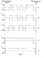
Figur 2 zeigt den Verlauf des Schaltzustands (aktiviert - EIN bzw. deaktiviert - AUS) der Bauteile im Motorstromkreis 20 und im Türverriegelungsstromkreis 30 in Abhängigkeit von der Zeit. Der Waschprogrammanfang ist durch die erste senkrechte Linie und das Waschprogrammende durch die zweite senkrechte Linie gekennzeichnet. Die Figuren 2a, 2b und 2c beziehen sich auf Bauelemente im Motorstromkreis 20, die Figuren 2d und 2e auf Bauelemente des Türverriegelungsstromkreises 30.Figure 2 shows the course of the switching state (activated - ON or OFF - OFF) of the components in the
Ein Waschprogramm beginnt, indem nach einer gewissen Zeit t gemäß Figur 2d der Triac 31 angesteuert wird und dieser bis zum Ende des Waschvorgangs aktiviert bleibt. Mit dem Ende des Waschvorgangs, kurz vor Ende des Wachprogramms, wird der Triac 31 stromlos geschaltet, also das Bimetallverriegelungselement 32 nicht mehr bestromt.A washing program begins by the
Kurz nach der Aktivierung des Triacs 31 erreicht das PTC-Bimetallelement 32 seine Betriebstemperatur und verriegelt den Türverschluss, wie in Figur 2e dargestellt, auch über das Ende des Waschvorgangs hinaus, bis zum Ende des Waschprogramms. Erst mit Ende des Waschprogramms ist es wieder möglich die Waschmaschinentüre zu öffnen.Shortly after activation of the
Eine zusätzliche Steuersoftware zum Abgleich der Schaltzustände der Schaltelemente 21 und 31 stellt sicher, dass wie in Figur 2a dargestellt, erst nachdem der Türverschluss durch das PTC-Bimetallelement 32 verriegelt ist der Triac 31 aktiviert und der Motorstromkreis 20 bestromt wird.Additional control software for balancing the switching states of the
Figur 2b zeigt, dass ab der Aktivierung des Triacs 21 der Antrieb der Wäschetrommel durch den Waschmotor 22 möglich ist, sofern die Relais 23.1 und 23.2 sich in einer solchen Schaltstellung befinden, dass der Motor 22 aktivgeschaltet ist (Figur 2c). Die ist bei bekannten Schaltungslösungen des Standes der Technik immer so.Figure 2b shows that from the activation of the
Eine Unterbrechung der Waschmotorbewegung (Figur 2b) lässt sich durch Deaktivierung des Triacs 21 (Figur 2a) erzielen. Mit Ablauf des Waschvorgangs, beziehungsweise mit der letztmaligen Deaktivierung des Triacs 21 (Figur 2a) und der damit beendeten Waschmotorbewegung (Figur 2b) kann zeitgleich der Triac 31 deaktiviert werden, was, wie erwähnt nach Ablauf von mindestens 30 sec Verzögerungszeit, mit dem Ende des Waschprogramms eine Öffnung der Waschmaschinentür möglich macht.An interruption of the washing motor movement (FIG. 2 b) can be achieved by deactivating the triac 21 (FIG. 2 a). At the end of the washing process, or with the last deactivation of the triac 21 (FIG. 2a) and the washing motor movement (FIG. 2b) ended therewith, the
Figur 3 zeigt eine dem Gedanken der vorliegenden Erfindung entsprechende Schaltung 40 zur Ansteuerung einer Waschmaschine mit einem Motorstromkreis 20 und einem Türverriegelungsstromkreis 30, wobei beide Stromkreise 20 und 30 über ein einziges gemeinsames elektronisches Schaltelement 41, wie einem Triac bestrombar sind.FIG. 3 shows a
Der prinzipielle Aufbau des Motorstromkreises 20 und des Türverriegelungsstromkreises 30 entspricht dem jeweiligen Aufbau wie er für Figur 1 beschrieben worden ist. Auf die Beschreibung zu Figur 1 wird daher Bezug genommen. Allerdings wäre zum Zweck der Drehrichtungsumkehrbarkeit bzw. Motorabschaltung auch eine Verschaltung der zwei Relais 23.1 und 23.2 mit der das Feld erzeugenden Wicklung des Waschmotors 22.2 möglich. Das optionale weitere Relais 24 könnte auch an der Rotorwicklung des Waschmotors 22.1 angeschlossen sein. Es ist beispielsweise auch eine Anordnung möglich, bei der ein Relais nur zur Drehrichtungsumkehr und ein Relais nur zur Unterbrechung des Motorstromkreises eingesetzt wird.The basic structure of the
Der wesentliche Unterschied zwischen Schaltung 40 und Schaltung 10 ist, dass in Schaltung 40 der Türverriegelungsstromkreis 30 hinter dem einzigen gemeinsamen elektronischen Schaltelement 41 mit dem Motorstromkreis 20 verschaltet ist. Dadurch sind der Motorstromkreis 20 und der Türverriegelungsstromkreis 30 gemeinsam durch Aktivierung bloß eines Triacs 41 bestrombar und auch gemeinsam abschaltbar.The essential difference between
Die gleichzeitige Bestromung von Motorstromkreis 20 und Türverriegelungsstromkreis 30 ist allerdings auch entkoppelbar. Diese Entkopplung geschieht durch die Nutzung der Relais 23.1 und 23.2 und ist ein herausragendes Merkmal der vorliegenden Erfindung. Denn während der Türverriegelungsstromkreis 30 aktiv bleibt, ist der Waschmotor 22 und damit der der Antrieb der Wäschetrommel mittels der Relais 23.1 und 23.2 abschaltbar. In diesem Fall bliebe die Waschmaschinentüre beispielsweise aus Sicherheitsgründen verriegelt, obwohl der Motor 22 zeitweilig abgeschaltet ist.However, the simultaneous energization of
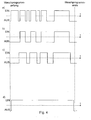
In Figur 4 ist der Verlauf des Schaltzustands (aktiviert - EIN bzw. deaktiviert - AUS) der Bauteile der Schaltung 40 nach Figur 3 im Motorstromkreis 20 und im Türverriegelungsstromkreis 30 in Abhängigkeit von der Zeit dargestellt. Der Waschprogrammanfang ist durch die erste senkrechte Linie und das Waschprogrammende durch die zweite senkrechte Linie gekennzeichnet. Figur 4a bezieht sich auf das Schaltelement 41. Die Figuren 4b und 4c beziehen sich auf Bauelemente im Motorstromkreis 20. Figur 4d bezieht sich auf den Türverriegelungsstromkreis 30.FIG. 4 shows the course of the switching state (activated-ON or deactivated-OFF) of the components of the
Ein Waschprogramm beginnt, indem nach einer gewissen Zeit t gemäß Figur 4a der gemeinsame Triac 41 angesteuert wird.A washing program begins by the
Kurz nach der Aktivierung des Triacs 41 erreicht das PTC-Bimetallelement 32 seine Betriebstemperatur und verriegelt den Türverschluss, wie in Figur 4d dargestellt, auch über das Ende des Waschvorgangs hinaus bis zum Ende des Waschprogramms. Erst jetzt ist es wieder möglich die Waschmaschinentüre zu öffnen.Shortly after activation of the
Obwohl gleichzeitig mit dem Türverriegelungsstromkreis 30 auch der Motorstromkreis 20 bestromt wird, setzt wie Figur 4b zeigt der Antrieb der Wäschetrommel durch den Waschmotor 22 erst nach einiger Zeit ein.Although the
Wie Figur 4c zeigt hängt dies damit zusammen, dass zunächst die Relais 23.1 und 23.2 durchgängig geschaltet werden müssen, um einen Stromfluss durch den Waschmotor 22 zu ermöglichen. Anders ausgedrückt, über die Schaltung der Relais 23.1 und 23.2 ist die Bestromung des Waschmotors 22 unterbrechbar.As shown in FIG. 4 c, this is due to the fact that initially the relays 23. 1 and 23. 2 must be switched continuously in order to allow a flow of current through the washing motor 22. In other words, via the circuit of the relays 23.1 and 23.2, the energization of the washing motor 22 can be interrupted.
Im Gegensatz zur bekannten Schaltung (Figur 1) erfordert die Schaltung nach Figur 3 keine zusätzliche Steuersoftware, die den Schaltzustand zweier Schaltelemente 21 und 31 überwacht. Denn über das einzige Steuerelement 41 werden sowohl der Motorstromkreis 20 als auch das PTC-Bimetallelement 32 im Türverriegelungsstromkreis 30 bestromt, so dass die Waschmaschinentüre immer sicher verriegelt ist, solange das Steuerelement 41 aktiv ist.In contrast to the known circuit (Figure 1), the circuit of Figure 3 requires no additional control software that monitors the switching state of two switching
Eine Unterbrechung der Waschmotorbewegung (Figur 4b) lässt sich einerseits durch Deaktivierung des Triacs 41 (Figur 4a) oder andererseits durch Unterbrechung der Stromzufuhr durch die Relais 23.1 und 23.2 erzielen (Figur 4c). Allerdings wird, um die Kontakte der Relais 23.1 und 23.2 zu schonen, zunächst der Motorstromkreis 20 (nebst Türverriegelungsstromkreis 30) über den Triac 41 stromlos geschaltet (Figur 4a), in diesem Schaltzustand über die Relais 23.1 und 23.2 (Figur 4c) der Motorzustand umgeschaltet und anschließend über den Triac 41 der Stromfluss wieder zugeschaltet (Figur 4a). Folglich entsteht der "Schaltfunke" am Triac 41, aber nicht an den Kontakten der Relais 23.1 und 23.2.An interruption of the washing motor movement (FIG. 4b) can be achieved on the one hand by deactivating the triac 41 (FIG. 4a) or on the other hand by interrupting the power supply through the relays 23.1 and 23.2 (FIG. 4c). However, to save the contacts of the relays 23.1 and 23.2, first the motor circuit 20 (together with door lock circuit 30) via the
Infolge der nachlaufenden Verriegelung durch das PTC-Bimetallelement 32 im Türverriegelungsstromkreis 30 bleibt der Türverschluss bis zum Ende des Waschvorgangs (Figur 4d) verriegelt, auch wenn das Schaltelement 41 kurzzeitig während des Waschvorgangs deaktiviert werden sollte (Figur 4a). Mit dem Ende des Waschvorgangs, kurz vor Ende des Wachprogramms, wird der Triac 41 dauerhaft stromlos geschaltet, bis sich die nachlaufende Verriegelung löst und das Öffnen der Türe gefahrlos ermöglicht, da die Wäschetrommel in der Zwischenzeit angehalten hat.Due to the trailing lock by the PTC
Falls der Waschmotor 22 während des Waschprogramms über längere Zeit ausgeschaltet bleiben muss, kann bei ausgeschalteten Relais 23.1 und 23.2 der Türverriegelungsstromkreis durch Einschalten des Triacs 41 auch während des Programms bestromt werden, ohne dass dabei dar Motor angesteuert wird (Figur 4a).If the washing motor 22 must remain switched off during the wash program for a long time, can be energized by turning on the
Claims (6)
dadurch gekennzeichnet,
dass der Motorstromkreis (20) und der Türverriegelungsstromkreis (30) über ein einziges gemeinsames elektronisches Schaltelement (41) ansteuerbar sind.A circuit for driving a laundry treatment apparatus, the circuit comprising a motor circuit (20) having an AC motor (22) and a door latch circuit (30),
characterized,
in that the motor circuit (20) and the door locking circuit (30) can be activated via a single common electronic switching element (41).
dadurch gekennzeichnet,
dass der Türverriegelungsstromkreis (30) bei Ansteuerung über das einzige gemeinsame elektronische Schaltelement (41) durchgängig geschaltet ist, wobei der Motorstromkreis (20) gleichzeitig durch wenigsten einen elektromechanischen Schalter (23) unterbrechbar ist.Circuit according to claim 1,
characterized,
in that the door locking circuit (30) is switched through continuously when actuated via the single common electronic switching element (41), wherein the motor circuit (20) can be interrupted simultaneously by at least one electromechanical switch (23).
dadurch gekennzeichnet,
dass das einzige elektronische Schaltelement (41) ein Triac oder ein Tyristor ist.Circuit according to a preceding claim,
characterized,
that the single electronic switching element (41) is a triac or a thyristor.
dadurch gekennzeichnet,
dass der Türverriegelungsstromkreis (30) einen Schalter (32) und/oder einen Mechanismus zur Verriegelung der Gerätetür aufweist, der durch ein PTC-Bimetallelement ansteuerbar ist.Circuit according to a preceding claim,
characterized,
in that the door locking circuit (30) has a switch (32) and / or a mechanism for locking the door, which can be activated by a PTC bimetallic element.
dadurch gekennzeichnet,
dass zwei elektromechanische Schalter (23.1, 23.2) im Motorstromkreis einsetzbar sind, die mit der Wicklung des AC-Motorrotors (22.1) oder mit der Wicklung des AC-Motorfeldes (22.2) verschaltet sind und in einem ersten Schaltzustand den Motorstromkreis (20) unterbrechen und in einem zweiten Schaltzustand eine Drehrichtungsumkehr des AC-Motors (22) bewirken.Circuit according to a preceding claim,
characterized,
that two electromechanical switches (23.1, 23.2) can be used in the motor circuit, which are connected to the winding of the AC motor rotor (22.1) or to the winding of the AC motor field (22.2) and interrupt the motor circuit (20) in a first switching state and cause in a second switching state, a reversal of the direction of rotation of the AC motor (22).
dadurch gekennzeichnet,
dass der Motorstromkreis (20) neben den zwei elektromechanischen Schaltern (23.1, 23.2) zur Drehrichtungsumkehr des AC-Motors (22) und zur Unterbrechung des Motorstromes einen weiteren elektromechanischen Schalter Relais (24) zur Feldumschaltung aufweist, wobei der elektromechanische Schalter (24) zur Feldumschaltung mit der jeweils anderen Wicklung des AC-Motors (22) verschaltet ist, als die Wicklung, die mit den zwei elektromechanischen Schaltern (23.1, 23.2) zur Drehrichtungsumkehr und Unterbrechung des Motorstroms verschaltet ist.Circuit according to Claim 5,
characterized,
that the motor circuit (20) in addition to the two electromechanical switches (23.1, 23.2) for reversing the direction of rotation of the AC motor (22) and to interrupt the motor current, a further electromechanical switch relay (24) for field switching, wherein the electromechanical switch (24) for Field switching is connected to the other winding of the AC motor (22), as the winding, which is connected to the two electromechanical switches (23.1, 23.2) for reversing the direction of rotation and interrupting the motor current.
Priority Applications (1)
| Application Number | Priority Date | Filing Date | Title |
|---|---|---|---|
| PL06021379T PL1775366T3 (en) | 2005-10-17 | 2006-10-12 | Control circuit for fabric treatment devices |
Applications Claiming Priority (1)
| Application Number | Priority Date | Filing Date | Title |
|---|---|---|---|
| DE200510049892 DE102005049892B3 (en) | 2005-10-17 | 2005-10-17 | Circuit for controlling a device for laundry treatment |
Publications (2)
| Publication Number | Publication Date |
|---|---|
| EP1775366A1 true EP1775366A1 (en) | 2007-04-18 |
| EP1775366B1 EP1775366B1 (en) | 2010-12-22 |
Family
ID=37607434
Family Applications (1)
| Application Number | Title | Priority Date | Filing Date |
|---|---|---|---|
| EP20060021379 Not-in-force EP1775366B1 (en) | 2005-10-17 | 2006-10-12 | Control circuit for fabric treatment devices |
Country Status (7)
| Country | Link |
|---|---|
| US (1) | US7420345B2 (en) |
| EP (1) | EP1775366B1 (en) |
| CN (1) | CN1952249B (en) |
| AT (1) | ATE492675T1 (en) |
| DE (2) | DE102005049892B3 (en) |
| ES (1) | ES2356753T3 (en) |
| PL (1) | PL1775366T3 (en) |
Cited By (4)
| Publication number | Priority date | Publication date | Assignee | Title |
|---|---|---|---|---|
| WO2009000690A1 (en) * | 2007-06-26 | 2008-12-31 | Arcelik Anonim Sirketi | A washer/dryer |
| WO2009007380A1 (en) * | 2007-07-10 | 2009-01-15 | Elmarc Societa' Per Azioni | System and electronic circuit used to protect the door of washing machines or washer-driers |
| FR2951332A1 (en) * | 2009-10-12 | 2011-04-15 | Fagorbrandt Sas | Capacitive power supply circuit i.e. capacitive feeding circuit for electrical appliance i.e. electric household appliance such as clothes washing machine, has first energy transformation unit provided first supply current signal |
| WO2012038311A3 (en) * | 2010-09-22 | 2012-05-18 | Arcelik Anonim Sirketi | Door lock for a washing machine |
Families Citing this family (4)
| Publication number | Priority date | Publication date | Assignee | Title |
|---|---|---|---|---|
| DE102007031882B4 (en) * | 2007-07-09 | 2016-07-21 | Diehl Ako Stiftung & Co. Kg | Laundry treatment device with door locking element |
| US9487907B2 (en) | 2009-09-10 | 2016-11-08 | Illinois Tool Works, Inc. | Appliance lock with mechanical door sensor |
| CN102361447B (en) * | 2011-06-01 | 2013-04-10 | 刘德军 | Single-bond control switch having self-locking function |
| CN102978886B (en) * | 2012-11-29 | 2015-04-15 | 无锡小天鹅股份有限公司 | Interlock control device and clothes dryer with same |
Citations (4)
| Publication number | Priority date | Publication date | Assignee | Title |
|---|---|---|---|---|
| GB2048314A (en) * | 1979-05-14 | 1980-12-10 | Ti Domestic Appliances Ltd | Improvements In and Relating To Electrical Machines |
| DE3423004A1 (en) * | 1984-06-22 | 1986-01-02 | Miele & Cie GmbH & Co, 4830 Gütersloh | Control arrangement for a program-controlled washing machine |
| EP0702103A1 (en) * | 1994-09-13 | 1996-03-20 | ELECTROLUX ZANUSSI ELETTRODOMESTICI S.p.A. | Improvement in the control arrangement of a clothes washing machine |
| DE19953633A1 (en) * | 1999-11-09 | 2001-05-10 | Diehl Ako Stiftung Gmbh & Co | Control device of a washing machine or dryer |
Family Cites Families (16)
| Publication number | Priority date | Publication date | Assignee | Title |
|---|---|---|---|---|
| US3597943A (en) * | 1969-06-17 | 1971-08-10 | Braun Inc G A | Sterilized laundry system |
| US3745382A (en) * | 1972-02-18 | 1973-07-10 | Rhomega Syst Inc | Solid state timer circuit for controlling the energization time of a load |
| IT994158B (en) * | 1973-08-21 | 1975-10-20 | Texas Instruments Italia Spa | LOCKING DEVICE WITH VOLTMETRIC OPERATED THERMAL DELAY SWITCH FOR DOORS |
| US4074545A (en) * | 1976-08-26 | 1978-02-21 | Franklin Manufacturing Company | Bimetal lid lock |
| US4120013A (en) * | 1977-03-28 | 1978-10-10 | Ametek, Inc. | Laundry machine control system |
| US4194182A (en) * | 1977-08-23 | 1980-03-18 | Martin James L | Electrical switch controllable alternatively by an internal timer and by digital information from a remote source |
| US4198563A (en) * | 1978-07-24 | 1980-04-15 | Elssner Egon H | Photodetector timer network |
| US4349748A (en) * | 1979-03-21 | 1982-09-14 | Dynascan Corporation | Timer and power control system |
| US4344000A (en) * | 1979-03-21 | 1982-08-10 | Dynascan Corporation | Power circuit control programmable timer |
| US4494012A (en) * | 1981-10-26 | 1985-01-15 | Intermatic Incorporated | Switch timer |
| US4493410A (en) * | 1982-12-27 | 1985-01-15 | The Maytag Company | Double actuation coin slide system |
| US4623179A (en) * | 1983-12-27 | 1986-11-18 | The Maytag Company | Door latch for appliance |
| US4981024A (en) * | 1989-02-03 | 1991-01-01 | Belco Equipment, Inc. | Apparatus, system, and method for dispensing laundry chemicals |
| US5655394A (en) * | 1996-03-22 | 1997-08-12 | Dirocco, Jr.; Charles J. | Security locking device for coin-operated appliance |
| DE20008430U1 (en) * | 2000-05-10 | 2001-09-13 | Diehl Ako Stiftung Gmbh & Co | Electrical control device of a washing machine or dryer |
| US7036175B2 (en) * | 2002-02-19 | 2006-05-02 | Maytag Corporation | Washing machine with pay activated bulk detergent dispenser |
-
2005
- 2005-10-17 DE DE200510049892 patent/DE102005049892B3/en not_active Expired - Fee Related
-
2006
- 2006-09-21 US US11/524,689 patent/US7420345B2/en not_active Expired - Fee Related
- 2006-10-12 DE DE200650008546 patent/DE502006008546D1/en active Active
- 2006-10-12 CN CN2006101321753A patent/CN1952249B/en not_active Expired - Fee Related
- 2006-10-12 PL PL06021379T patent/PL1775366T3/en unknown
- 2006-10-12 EP EP20060021379 patent/EP1775366B1/en not_active Not-in-force
- 2006-10-12 AT AT06021379T patent/ATE492675T1/en active
- 2006-10-12 ES ES06021379T patent/ES2356753T3/en active Active
Patent Citations (4)
| Publication number | Priority date | Publication date | Assignee | Title |
|---|---|---|---|---|
| GB2048314A (en) * | 1979-05-14 | 1980-12-10 | Ti Domestic Appliances Ltd | Improvements In and Relating To Electrical Machines |
| DE3423004A1 (en) * | 1984-06-22 | 1986-01-02 | Miele & Cie GmbH & Co, 4830 Gütersloh | Control arrangement for a program-controlled washing machine |
| EP0702103A1 (en) * | 1994-09-13 | 1996-03-20 | ELECTROLUX ZANUSSI ELETTRODOMESTICI S.p.A. | Improvement in the control arrangement of a clothes washing machine |
| DE19953633A1 (en) * | 1999-11-09 | 2001-05-10 | Diehl Ako Stiftung Gmbh & Co | Control device of a washing machine or dryer |
Cited By (6)
| Publication number | Priority date | Publication date | Assignee | Title |
|---|---|---|---|---|
| WO2009000690A1 (en) * | 2007-06-26 | 2008-12-31 | Arcelik Anonim Sirketi | A washer/dryer |
| CN101688355B (en) * | 2007-06-26 | 2012-05-23 | 阿塞里克股份有限公司 | A washer/dryer |
| US8590346B2 (en) | 2007-06-26 | 2013-11-26 | Arcelik Anonim Sirketi | Washer/dryer |
| WO2009007380A1 (en) * | 2007-07-10 | 2009-01-15 | Elmarc Societa' Per Azioni | System and electronic circuit used to protect the door of washing machines or washer-driers |
| FR2951332A1 (en) * | 2009-10-12 | 2011-04-15 | Fagorbrandt Sas | Capacitive power supply circuit i.e. capacitive feeding circuit for electrical appliance i.e. electric household appliance such as clothes washing machine, has first energy transformation unit provided first supply current signal |
| WO2012038311A3 (en) * | 2010-09-22 | 2012-05-18 | Arcelik Anonim Sirketi | Door lock for a washing machine |
Also Published As
| Publication number | Publication date |
|---|---|
| CN1952249B (en) | 2011-04-27 |
| PL1775366T3 (en) | 2011-07-29 |
| ATE492675T1 (en) | 2011-01-15 |
| DE102005049892B3 (en) | 2007-05-03 |
| CN1952249A (en) | 2007-04-25 |
| US7420345B2 (en) | 2008-09-02 |
| US20070085503A1 (en) | 2007-04-19 |
| EP1775366B1 (en) | 2010-12-22 |
| DE502006008546D1 (en) | 2011-02-03 |
| ES2356753T3 (en) | 2011-04-12 |
Similar Documents
| Publication | Publication Date | Title |
|---|---|---|
| EP1775366B1 (en) | Control circuit for fabric treatment devices | |
| EP2217754B1 (en) | Circuit arrangements for operating a household appliance | |
| EP1960582B1 (en) | Circuit arrangement for locking and/or unlocking a door lock, especially in an electric appliance | |
| EP1250749B1 (en) | Electrical switching device | |
| EP2220737B1 (en) | Circuit configuration for operating a household appliance | |
| EP1532306A2 (en) | Household machine | |
| DE102007031882B4 (en) | Laundry treatment device with door locking element | |
| EP1099790B1 (en) | Controlling device for a washing machine or a laundry dryer | |
| EP2020721B1 (en) | Switching assembly for monitoring a tachometer for a drive motor of a drum of a washing machine | |
| DE4414984A1 (en) | Soft start of the drive motors of a rotor spinning machine | |
| EP0499123B1 (en) | Method and circuit overspeed protection of driving motors in electronically controlled devices, particularly in household washing machines | |
| WO2009121854A1 (en) | Circuit arrangement for operating a domestic appliance and a corresponding method | |
| EP1962011B1 (en) | Laundry treatment apparatus | |
| DE102013202969A1 (en) | Domestic appliance, in particular tumble dryer, with a brushless DC motor and method for operating a brushless DC motor in a household appliance | |
| DE1585853C3 (en) | Arrangement for the electrical locking of the drive motors of a washing machine | |
| EP3488042B1 (en) | Door monitoring circuit for a domestic appliance | |
| DE724924C (en) | Device to prevent unauthorized interference in the operational speed control of spinning and twisting machines with thread tension regulators (spinning regulators) | |
| EP1154063A2 (en) | Electrical control device for a laundry washing or drying machine | |
| DE102006036956B4 (en) | Control unit for an electric drive motor | |
| DE19628723C2 (en) | Electric household appliance, in particular electric clothes dryer | |
| DE2166554A1 (en) | PROGRAM CONTROL | |
| DE102006054540B3 (en) | Operating unit controlling circuit for e.g. dishwasher, has two controlling units connected parallel to each other, so that controlling units are adjustable by common switching unit i.e. semiconductor switch | |
| DE202006020205U1 (en) | Circuit arrangement for the secure activation of actuators | |
| DE19750915A1 (en) | Control device for washing machine has electromagnetic programming unit | |
| DE2111714A1 (en) | Installation in program switches with overdrive drive for temporary interruption of the program sequence |
Legal Events
| Date | Code | Title | Description |
|---|---|---|---|
| PUAI | Public reference made under article 153(3) epc to a published international application that has entered the european phase |
Free format text: ORIGINAL CODE: 0009012 |
|
| AK | Designated contracting states |
Kind code of ref document: A1 Designated state(s): AT BE BG CH CY CZ DE DK EE ES FI FR GB GR HU IE IS IT LI LT LU LV MC NL PL PT RO SE SI SK TR |
|
| AX | Request for extension of the european patent |
Extension state: AL BA HR MK YU |
|
| 17P | Request for examination filed |
Effective date: 20070512 |
|
| 17Q | First examination report despatched |
Effective date: 20070619 |
|
| AKX | Designation fees paid |
Designated state(s): AT BE BG CH CY CZ DE DK EE ES FI FR GB GR HU IE IS IT LI LT LU LV MC NL PL PT RO SE SI SK TR |
|
| GRAP | Despatch of communication of intention to grant a patent |
Free format text: ORIGINAL CODE: EPIDOSNIGR1 |
|
| GRAS | Grant fee paid |
Free format text: ORIGINAL CODE: EPIDOSNIGR3 |
|
| GRAA | (expected) grant |
Free format text: ORIGINAL CODE: 0009210 |
|
| AK | Designated contracting states |
Kind code of ref document: B1 Designated state(s): AT BE BG CH CY CZ DE DK EE ES FI FR GB GR HU IE IS IT LI LT LU LV MC NL PL PT RO SE SI SK TR |
|
| REG | Reference to a national code |
Ref country code: GB Ref legal event code: FG4D Free format text: NOT ENGLISH |
|
| REG | Reference to a national code |
Ref country code: CH Ref legal event code: EP |
|
| REG | Reference to a national code |
Ref country code: IE Ref legal event code: FG4D |
|
| REF | Corresponds to: |
Ref document number: 502006008546 Country of ref document: DE Date of ref document: 20110203 Kind code of ref document: P |
|
| REG | Reference to a national code |
Ref country code: DE Ref legal event code: R096 Ref document number: 502006008546 Country of ref document: DE Effective date: 20110203 |
|
| REG | Reference to a national code |
Ref country code: ES Ref legal event code: FG2A Ref document number: 2356753 Country of ref document: ES Kind code of ref document: T3 Effective date: 20110412 |
|
| REG | Reference to a national code |
Ref country code: NL Ref legal event code: VDEP Effective date: 20101222 |
|
| PG25 | Lapsed in a contracting state [announced via postgrant information from national office to epo] |
Ref country code: LT Free format text: LAPSE BECAUSE OF FAILURE TO SUBMIT A TRANSLATION OF THE DESCRIPTION OR TO PAY THE FEE WITHIN THE PRESCRIBED TIME-LIMIT Effective date: 20101222 |
|
| LTIE | Lt: invalidation of european patent or patent extension |
Effective date: 20101222 |
|
| PG25 | Lapsed in a contracting state [announced via postgrant information from national office to epo] |
Ref country code: FI Free format text: LAPSE BECAUSE OF FAILURE TO SUBMIT A TRANSLATION OF THE DESCRIPTION OR TO PAY THE FEE WITHIN THE PRESCRIBED TIME-LIMIT Effective date: 20101222 Ref country code: SE Free format text: LAPSE BECAUSE OF FAILURE TO SUBMIT A TRANSLATION OF THE DESCRIPTION OR TO PAY THE FEE WITHIN THE PRESCRIBED TIME-LIMIT Effective date: 20101222 Ref country code: LV Free format text: LAPSE BECAUSE OF FAILURE TO SUBMIT A TRANSLATION OF THE DESCRIPTION OR TO PAY THE FEE WITHIN THE PRESCRIBED TIME-LIMIT Effective date: 20101222 Ref country code: BG Free format text: LAPSE BECAUSE OF FAILURE TO SUBMIT A TRANSLATION OF THE DESCRIPTION OR TO PAY THE FEE WITHIN THE PRESCRIBED TIME-LIMIT Effective date: 20110322 Ref country code: CY Free format text: LAPSE BECAUSE OF FAILURE TO SUBMIT A TRANSLATION OF THE DESCRIPTION OR TO PAY THE FEE WITHIN THE PRESCRIBED TIME-LIMIT Effective date: 20101222 Ref country code: SI Free format text: LAPSE BECAUSE OF FAILURE TO SUBMIT A TRANSLATION OF THE DESCRIPTION OR TO PAY THE FEE WITHIN THE PRESCRIBED TIME-LIMIT Effective date: 20101222 |
|
| REG | Reference to a national code |
Ref country code: IE Ref legal event code: FD4D |
|
| PG25 | Lapsed in a contracting state [announced via postgrant information from national office to epo] |
Ref country code: GR Free format text: LAPSE BECAUSE OF FAILURE TO SUBMIT A TRANSLATION OF THE DESCRIPTION OR TO PAY THE FEE WITHIN THE PRESCRIBED TIME-LIMIT Effective date: 20110323 Ref country code: EE Free format text: LAPSE BECAUSE OF FAILURE TO SUBMIT A TRANSLATION OF THE DESCRIPTION OR TO PAY THE FEE WITHIN THE PRESCRIBED TIME-LIMIT Effective date: 20101222 Ref country code: IS Free format text: LAPSE BECAUSE OF FAILURE TO SUBMIT A TRANSLATION OF THE DESCRIPTION OR TO PAY THE FEE WITHIN THE PRESCRIBED TIME-LIMIT Effective date: 20110422 Ref country code: CZ Free format text: LAPSE BECAUSE OF FAILURE TO SUBMIT A TRANSLATION OF THE DESCRIPTION OR TO PAY THE FEE WITHIN THE PRESCRIBED TIME-LIMIT Effective date: 20101222 Ref country code: PT Free format text: LAPSE BECAUSE OF FAILURE TO SUBMIT A TRANSLATION OF THE DESCRIPTION OR TO PAY THE FEE WITHIN THE PRESCRIBED TIME-LIMIT Effective date: 20110422 |
|
| REG | Reference to a national code |
Ref country code: PL Ref legal event code: T3 |
|
| PG25 | Lapsed in a contracting state [announced via postgrant information from national office to epo] |
Ref country code: SK Free format text: LAPSE BECAUSE OF FAILURE TO SUBMIT A TRANSLATION OF THE DESCRIPTION OR TO PAY THE FEE WITHIN THE PRESCRIBED TIME-LIMIT Effective date: 20101222 Ref country code: NL Free format text: LAPSE BECAUSE OF FAILURE TO SUBMIT A TRANSLATION OF THE DESCRIPTION OR TO PAY THE FEE WITHIN THE PRESCRIBED TIME-LIMIT Effective date: 20101222 Ref country code: RO Free format text: LAPSE BECAUSE OF FAILURE TO SUBMIT A TRANSLATION OF THE DESCRIPTION OR TO PAY THE FEE WITHIN THE PRESCRIBED TIME-LIMIT Effective date: 20101222 |
|
| PLBE | No opposition filed within time limit |
Free format text: ORIGINAL CODE: 0009261 |
|
| STAA | Information on the status of an ep patent application or granted ep patent |
Free format text: STATUS: NO OPPOSITION FILED WITHIN TIME LIMIT |
|
| PG25 | Lapsed in a contracting state [announced via postgrant information from national office to epo] |
Ref country code: DK Free format text: LAPSE BECAUSE OF FAILURE TO SUBMIT A TRANSLATION OF THE DESCRIPTION OR TO PAY THE FEE WITHIN THE PRESCRIBED TIME-LIMIT Effective date: 20101222 Ref country code: IE Free format text: LAPSE BECAUSE OF FAILURE TO SUBMIT A TRANSLATION OF THE DESCRIPTION OR TO PAY THE FEE WITHIN THE PRESCRIBED TIME-LIMIT Effective date: 20101222 |
|
| 26N | No opposition filed |
Effective date: 20110923 |
|
| REG | Reference to a national code |
Ref country code: DE Ref legal event code: R097 Ref document number: 502006008546 Country of ref document: DE Effective date: 20110923 |
|
| BERE | Be: lapsed |
Owner name: DIEHL AKO STIFTUNG & CO. K.G. Effective date: 20111031 |
|
| PG25 | Lapsed in a contracting state [announced via postgrant information from national office to epo] |
Ref country code: MC Free format text: LAPSE BECAUSE OF NON-PAYMENT OF DUE FEES Effective date: 20111031 |
|
| REG | Reference to a national code |
Ref country code: CH Ref legal event code: PL |
|
| GBPC | Gb: european patent ceased through non-payment of renewal fee |
Effective date: 20111012 |
|
| PG25 | Lapsed in a contracting state [announced via postgrant information from national office to epo] |
Ref country code: LI Free format text: LAPSE BECAUSE OF NON-PAYMENT OF DUE FEES Effective date: 20111031 Ref country code: BE Free format text: LAPSE BECAUSE OF NON-PAYMENT OF DUE FEES Effective date: 20111031 Ref country code: CH Free format text: LAPSE BECAUSE OF NON-PAYMENT OF DUE FEES Effective date: 20111031 |
|
| PG25 | Lapsed in a contracting state [announced via postgrant information from national office to epo] |
Ref country code: GB Free format text: LAPSE BECAUSE OF NON-PAYMENT OF DUE FEES Effective date: 20111012 |
|
| REG | Reference to a national code |
Ref country code: AT Ref legal event code: MM01 Ref document number: 492675 Country of ref document: AT Kind code of ref document: T Effective date: 20111012 |
|
| PG25 | Lapsed in a contracting state [announced via postgrant information from national office to epo] |
Ref country code: AT Free format text: LAPSE BECAUSE OF NON-PAYMENT OF DUE FEES Effective date: 20111012 |
|
| PG25 | Lapsed in a contracting state [announced via postgrant information from national office to epo] |
Ref country code: LU Free format text: LAPSE BECAUSE OF NON-PAYMENT OF DUE FEES Effective date: 20111012 |
|
| PG25 | Lapsed in a contracting state [announced via postgrant information from national office to epo] |
Ref country code: TR Free format text: LAPSE BECAUSE OF FAILURE TO SUBMIT A TRANSLATION OF THE DESCRIPTION OR TO PAY THE FEE WITHIN THE PRESCRIBED TIME-LIMIT Effective date: 20101222 |
|
| PG25 | Lapsed in a contracting state [announced via postgrant information from national office to epo] |
Ref country code: HU Free format text: LAPSE BECAUSE OF FAILURE TO SUBMIT A TRANSLATION OF THE DESCRIPTION OR TO PAY THE FEE WITHIN THE PRESCRIBED TIME-LIMIT Effective date: 20101222 |
|
| REG | Reference to a national code |
Ref country code: FR Ref legal event code: PLFP Year of fee payment: 10 |
|
| PGFP | Annual fee paid to national office [announced via postgrant information from national office to epo] |
Ref country code: IT Payment date: 20151028 Year of fee payment: 10 |
|
| PGFP | Annual fee paid to national office [announced via postgrant information from national office to epo] |
Ref country code: FR Payment date: 20151023 Year of fee payment: 10 Ref country code: ES Payment date: 20151028 Year of fee payment: 10 |
|
| REG | Reference to a national code |
Ref country code: FR Ref legal event code: ST Effective date: 20170630 |
|
| PG25 | Lapsed in a contracting state [announced via postgrant information from national office to epo] |
Ref country code: FR Free format text: LAPSE BECAUSE OF NON-PAYMENT OF DUE FEES Effective date: 20161102 |
|
| PG25 | Lapsed in a contracting state [announced via postgrant information from national office to epo] |
Ref country code: IT Free format text: LAPSE BECAUSE OF NON-PAYMENT OF DUE FEES Effective date: 20161012 |
|
| PGFP | Annual fee paid to national office [announced via postgrant information from national office to epo] |
Ref country code: DE Payment date: 20171212 Year of fee payment: 12 |
|
| PG25 | Lapsed in a contracting state [announced via postgrant information from national office to epo] |
Ref country code: ES Free format text: LAPSE BECAUSE OF NON-PAYMENT OF DUE FEES Effective date: 20161013 |
|
| REG | Reference to a national code |
Ref country code: ES Ref legal event code: FD2A Effective date: 20181128 |
|
| PGFP | Annual fee paid to national office [announced via postgrant information from national office to epo] |
Ref country code: PL Payment date: 20180924 Year of fee payment: 13 |
|
| REG | Reference to a national code |
Ref country code: DE Ref legal event code: R119 Ref document number: 502006008546 Country of ref document: DE |
|
| PG25 | Lapsed in a contracting state [announced via postgrant information from national office to epo] |
Ref country code: DE Free format text: LAPSE BECAUSE OF NON-PAYMENT OF DUE FEES Effective date: 20190501 |
|
| PG25 | Lapsed in a contracting state [announced via postgrant information from national office to epo] |
Ref country code: PL Free format text: LAPSE BECAUSE OF NON-PAYMENT OF DUE FEES Effective date: 20191012 |