EP1775207A1 - Straddle-type vehicle - Google Patents
Straddle-type vehicle Download PDFInfo
- Publication number
- EP1775207A1 EP1775207A1 EP06021652A EP06021652A EP1775207A1 EP 1775207 A1 EP1775207 A1 EP 1775207A1 EP 06021652 A EP06021652 A EP 06021652A EP 06021652 A EP06021652 A EP 06021652A EP 1775207 A1 EP1775207 A1 EP 1775207A1
- Authority
- EP
- European Patent Office
- Prior art keywords
- vehicle
- injection valve
- fuel injection
- straddle
- frame member
- Prior art date
- Legal status (The legal status is an assumption and is not a legal conclusion. Google has not performed a legal analysis and makes no representation as to the accuracy of the status listed.)
- Granted
Links
Images


Classifications
-
- F—MECHANICAL ENGINEERING; LIGHTING; HEATING; WEAPONS; BLASTING
- F02—COMBUSTION ENGINES; HOT-GAS OR COMBUSTION-PRODUCT ENGINE PLANTS
- F02B—INTERNAL-COMBUSTION PISTON ENGINES; COMBUSTION ENGINES IN GENERAL
- F02B61/00—Adaptations of engines for driving vehicles or for driving propellers; Combinations of engines with gearing
- F02B61/02—Adaptations of engines for driving vehicles or for driving propellers; Combinations of engines with gearing for driving cycles
-
- F—MECHANICAL ENGINEERING; LIGHTING; HEATING; WEAPONS; BLASTING
- F01—MACHINES OR ENGINES IN GENERAL; ENGINE PLANTS IN GENERAL; STEAM ENGINES
- F01N—GAS-FLOW SILENCERS OR EXHAUST APPARATUS FOR MACHINES OR ENGINES IN GENERAL; GAS-FLOW SILENCERS OR EXHAUST APPARATUS FOR INTERNAL-COMBUSTION ENGINES
- F01N3/00—Exhaust or silencing apparatus having means for purifying, rendering innocuous, or otherwise treating exhaust
- F01N3/08—Exhaust or silencing apparatus having means for purifying, rendering innocuous, or otherwise treating exhaust for rendering innocuous
- F01N3/10—Exhaust or silencing apparatus having means for purifying, rendering innocuous, or otherwise treating exhaust for rendering innocuous by thermal or catalytic conversion of noxious components of exhaust
- F01N3/18—Exhaust or silencing apparatus having means for purifying, rendering innocuous, or otherwise treating exhaust for rendering innocuous by thermal or catalytic conversion of noxious components of exhaust characterised by methods of operation; Control
- F01N3/22—Control of additional air supply only, e.g. using by-passes or variable air pump drives
-
- F—MECHANICAL ENGINEERING; LIGHTING; HEATING; WEAPONS; BLASTING
- F02—COMBUSTION ENGINES; HOT-GAS OR COMBUSTION-PRODUCT ENGINE PLANTS
- F02M—SUPPLYING COMBUSTION ENGINES IN GENERAL WITH COMBUSTIBLE MIXTURES OR CONSTITUENTS THEREOF
- F02M69/00—Low-pressure fuel-injection apparatus ; Apparatus with both continuous and intermittent injection; Apparatus injecting different types of fuel
- F02M69/04—Injectors peculiar thereto
- F02M69/042—Positioning of injectors with respect to engine, e.g. in the air intake conduit
- F02M69/044—Positioning of injectors with respect to engine, e.g. in the air intake conduit for injecting into the intake conduit downstream of an air throttle valve
-
- B—PERFORMING OPERATIONS; TRANSPORTING
- B62—LAND VEHICLES FOR TRAVELLING OTHERWISE THAN ON RAILS
- B62K—CYCLES; CYCLE FRAMES; CYCLE STEERING DEVICES; RIDER-OPERATED TERMINAL CONTROLS SPECIALLY ADAPTED FOR CYCLES; CYCLE AXLE SUSPENSIONS; CYCLE SIDECARS, FORECARS, OR THE LIKE
- B62K2202/00—Motorised scooters
-
- Y—GENERAL TAGGING OF NEW TECHNOLOGICAL DEVELOPMENTS; GENERAL TAGGING OF CROSS-SECTIONAL TECHNOLOGIES SPANNING OVER SEVERAL SECTIONS OF THE IPC; TECHNICAL SUBJECTS COVERED BY FORMER USPC CROSS-REFERENCE ART COLLECTIONS [XRACs] AND DIGESTS
- Y02—TECHNOLOGIES OR APPLICATIONS FOR MITIGATION OR ADAPTATION AGAINST CLIMATE CHANGE
- Y02A—TECHNOLOGIES FOR ADAPTATION TO CLIMATE CHANGE
- Y02A50/00—TECHNOLOGIES FOR ADAPTATION TO CLIMATE CHANGE in human health protection, e.g. against extreme weather
- Y02A50/20—Air quality improvement or preservation, e.g. vehicle emission control or emission reduction by using catalytic converters
Definitions
- the present invention relates to a straddle-type vehicle, in particular a motorcycle, having a stride part for facilitating a stride of a rider at the time of loading and unloading between a head pipe and a seat.
- Patent Reference 1 JP-A-2002-266724
- the invention has been implemented in view of the conventional circumstances described above, and an object of the invention is to provide a motorcycle capable of arranging a fuel injection valve so as to be oriented to the umbrella back of an intake valve and thus improving engine performance.
- a straddle-type vehicle in particular motorcycle, comprising a panel member formed between a head pipe and a seat, an engine mounted in a lower portion of the panel member, an intake passage connected to a cylinder head of a cylinder of the engine and extending backwards of the vehicle in the lower side of the panel member, and a throttle body arranged in a vicinity of an engine connection part of the intake passage, wherein a fuel injection valve is arranged inside a space surrounded by the throttle body, the cylinder head and the panel member, when viewed from the side of the vehicle.
- the panel member in particular a leg shield, constitutes a stride part for facilitating a stride of a rider at a time of loading and unloading.
- the cylinder may be arranged forwardly-tilted.
- the straddle-type vehicle further comprises a frame member, which is connected to the head pipe and extends toward a lower portion of the seat in a backward descending state, wherein the panel member is formed so as to cover the upper side, the left and right sides of said frame member and a stride part is in a backward descending state and the fuel injection valve is disposed so as to be located inside the space surrounded by the frame member, the throttle body and the cylinder head when viewed from the side of the vehicle.
- the frame member may have left and right side pipes in at least a part between the head pipe and the seat and the fuel injection valve may be arranged between the left and right side pipes when viewed from the above of the vehicle.
- the frame member has one main pipe, which is connected to the head pipe and extends to a backward oblique lower portion and left and right side pipes, which are connected to the back end of said main pipe and extend to a lower portion of the seat while expanding in a vehicle width direction and the fuel injection valve is arranged between the left and right side pipes in the vicinity of a connection part between said side pipes and the main pipe when viewed from the above of the vehicle.
- a fuel supply hose is connected to the fuel injection valve so as to incline to the back of the vehicle with respect to an axis line of said fuel injection valve and said fuel supply hose extends backward in the lower side of the panel member.
- the fuel supply hose may have the portion overlapping with the frame member when viewed from the side of the vehicle.
- the intake passage may extend to the back of the vehicle so as to pass between the left and right side pipes.
- the fuel supply hose may be connected to the fuel injection valve extends backward over the upper side of the throttle body.
- the straddle-type vehicle may further comprise a frame member which is connected to the head pipe and extends to a lower portion of the seat so as to be displaced to one side of a vehicle width direction in a backward descending state, wherein the panel member is formed so as to cover the upper side, the left and right sides of said frame member and the fuel injection valve is located in the other side of the frame member when viewed from the above of the vehicle and is located inside space surrounded by the panel member, the throttle body and the cylinder head when viewed from the side of the vehicle.
- the fuel injection valve is disposed so as to overlap with the frame member when viewed from the side of the vehicle.
- the straddle-type vehicle may further comprise a secondary air supply system for supplying secondary air to an exhaust system of the engine, characterized in that said secondary air supply system comprises a reed valve opened and closed by pulsation of the exhaust system and a resonator for attenuating a predetermined resonance frequency and said resonator is arranged in the lower side of the throttle body.
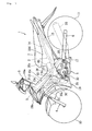
- Figs. 1 to 5 are diagrams describing a motorcycle according to a first embodiment.
- the term “forward and backward, left and right” shown in the present embodiment means “forward and backward, left and right” of the case of being viewed in a state of sitting on a seat.
- numeral 1 shows a motorcycle and this motorcycle comprises a vehicle body frame 2 of an under bone type, a front fork 4 pivoted by a head pipe 3 fixed in the front end of the vehicle body frame 2, an engine 5 suspended and supported in the center of the vehicle body frame 2, a rear arm 6 vertically swingably pivoted in the back side of the engine 5 of the vehicle body frame 2, and a seat 7 for two arranged on the vehicle body frame 2.
- a front wheel 10 is axially supported in the lower end of the front fork 4 and a rear wheel 11 is axially supported in the back end of the rear arm 6.
- a steering shaft 8 is axially supported in the head pipe 3 through a bearing (not shown).
- the front fork 4 is fixed in the lower end of this steering shaft 8 and a steering handle 9 is fixed in the upper end.
- the vehicle body frame 2 comprises a frame member 13 which is connected to the head pipe 3 and extends toward a lower portion of the seat 7 in a backward descending state.
- the frame member 13 has one main pipe 13a which is connected to the head pipe 3 and extends to a backward oblique lower portion of the vehicle, and one pair of left and right side pipes 13b, 13b which are connected to the back end of the main pipe 13a and extend to a backward oblique lower portion so as to be located in a lower portion of the seat 7 while expanding to the outside of a width direction of the vehicle.
- An axis line of the main pipe 13a and a center line of the vehicle width direction of the left and right side pipes 13b coincide with a vehicle body center line passing through an axis line of the head pipe 3.
- left and right seat rails 14, 14 extending in a backward oblique upper direction of the vehicle are connected to the backs of the left and right side pipes 13b. Also, the back ends of the left and right side pipes 13b and the back ends of the seat rails 14 are joined by left and right back stays 15, 15. Further, the fronts of the seat rails 14 and the left and right back stays 15 are mutually joined by left and right longitudinal pipes 16, 16.
- a rear arm bracket 17 extending downward is connected to the portion to which the back stays 15 of the back ends of the left and right side pipes 13b are connected.
- the rear arm 6 is supported in this rear arm bracket 17 by a pivot shaft 18.
- the vehicle body frame 2 is covered with a vehicle body cover 19.
- This vehicle body cover 19 has a handle cover 19a for covering the outer circumference of the steering handle 9, a front cover 19b for covering a front side portion of the head pipe 3, a leg shield 19c (panel member) for covering the upper side, the left and right sides of the frame member 13 between the seat 7 and the head pipe 3, and a side cover 19d for covering the downward circumference of the seat 7.
- the leg shield 19c constructs a backward descending stride part which inclines along the frame member 13 in a backward descending state and facilitates a stride of a rider at the time of loading and unloading.
- a fuel tank 22 is arranged in a downward portion of the seat 7 of the left and right seat rails 14 and a glove compartment 23 is arranged in the back side of the fuel tank 22.
- a battery box 26 in which a battery and fuse unit (not shown) is received is arranged in the front side of the fuel tank 22.
- the battery box 26 is fixed on the left and right seat rails 14.
- a hinge part 26a for vertically rotatably supporting the seat 7 is integrally formed in a front wall of the battery box 26.
- the fuel tank 22 has a structure in which a fuel inlet 24d is formed in an upper wall of a tank body 24 made by mutually bonding flange parts 24c of a lower tank 24a and an upper tank 24b. This fuel inlet 24d is openably blocked by a fuel cap 25.
- the tank body 24 is elastically supported in the left and right seat rails 14 through elastic bushings 27 attached to each of the corners of the flange parts 24c.
- the engine 5 is a water cooling type four-cycle one-cylinder engine mounted with a cylinder axis line A forward tilted.
- This engine 5 has a general structure in which a cylinder block 5b is coupled to an upper mesh surface of a crankcase 5a in which a crankshaft (not shown) is held in a width direction of the vehicle and a cylinder head 5c is coupled to an upper mesh surface of the cylinder block 5b and further a head cover 5d is attached to the cylinder head 5c.
- a transmission case part 5e in which a transmission unit (not shown) is held is integrally formed in the back side of the crankcase 5a.
- the cylinder head 5c is bolted and fixed to the main pipe 13a through left and right front side suspension brackets 28, and an upper wall of the crankcase 5a is bolted and fixed to the left and right side pipes 13b through an intermediate suspension bracket 29 and further, the lower end of a back side wall of the transmission case part 5e is bolted and fixed to a lower side bracket 17a of the rear arm bracket 17.
- a cooling water pump 30 is arranged in a left wall of the cylinder head 5c. This cooling water pump 30 is connected to a radiator 31 arranged in the oblique front of the engine 5 through a cooling water hose 30a.
- An exhaust system of the engine 5 has the following structure.
- An exhaust tube 33 in communication with an exhaust port (not shown) is connected to a front side wall of the cylinder head 5c.
- This exhaust tube 33 extends downward from the cylinder head 5c and bends backward therefrom and extends backward through a lower portion of the crankcase 5a.
- a muffler 34 arranged in the right side of the rear wheel 11 is connected to the downstream end of the exhaust tube 33.
- a catalyst 35 is interposed in the upstream side of the exhaust tube 33.
- An intake system of the engine 5 has the following structure.
- An intake tube 37 in communication with an intake port (not shown) is connected to a back side wall of the cylinder head 5c.
- This intake tube 37 extends substantially horizontally from the cylinder head 5c to the back of the vehicle and a throttle body 38 into which a throttle valve (not shown) is built is interposed in an intermediate part of the intake tube 37.
- an air cleaner 40 is connected to the back end of the intake tube 37. This air cleaner 40 is set at a predetermined capacity capable of securing the intake amount at the time of the maximum output of the engine 5.
- the air cleaner 40 comprises a cleaner body 40a with a bottomed rectangular parallelepiped shape extending in a vertical direction and a lid member 40b detachably attached to an upper end opening of the cleaner body 40a.
- the cleaner body 40a is manufactured using a metal mold in which a die cutting direction is a vertical direction (direction of an axis line B). That is, in the cleaner body 40a, a dimension of the upper end opening becomes larger than that of the bottom in a width direction and forward and backward directions of the vehicle.
- An air filter (not shown) is arranged inside the cleaner body 40a and the intake tube 37 is connected to a front wall of the cleaner body 40a.
- An inlet port 40c is formed in a rear surface of the lid member 40b.
- the air cleaner 40 is arranged with the axis line B forward tilted so as to become substantially parallel to the cylinder axis line A.
- the cleaner body 40a is received inside space formed in a connection part between the left and right side pipes 13b, 13b and the left and right seat rails 14, 14, and approximately upper half of the cleaner body 40a protrudes upward from the left and right seat rails 14.
- a secondary air supply system of the engine 5 has the following structure.
- the air cleaner 40 is communicated and connected to a downstream side portion of the catalyst 35 of the exhaust tube 33 by a secondary air supply hose 42 for supplying secondary air to the inside of the exhaust tube 33;
- a reed valve (not shown) opened and closed by pulsation of the exhaust system and a resonator 43 for attenuating a predetermined resonance frequency in the upstream side of the reed valve are interposed in the secondary air supply hose 42.
- the reed valve is arranged in the right side of the cylinder block 5b and the resonator 43 is arranged in a left lower portion of the throttle body 38 and is mounted and fixed in the throttle body 38.
- a fuel supply device is disposed in the engine 5.
- This fuel supply device comprises the fuel tank 22 arranged in the back of the air cleaner 40, a fuel injection valve 45 which is arranged in the front of the air cleaner 40 and is connected to the engine 5, a fuel hose 46 for making connection between the fuel injection valve 45 and the fuel tank 22, and a fuel pump 47 for pressurizing fuel of the inside of the fuel tank 22 and supplying the fuel to the fuel injection valve 45.
- the fuel pump 47 is received and arranged inside the fuel tank 22.
- An inlet (not shown) of the fuel pump 47 is located in the bottom of the tank and an outlet 47b protrudes backward from an upper wall of the tank body 24.
- the fuel hose 46 is connected to the outlet 47b of the fuel pump 47 and extends forward through the left side of the fuel tank 22 from the outlet 47b and is connected to the fuel injection valve 45 through the left side of the air cleaner 40, and specifically has the following structure.
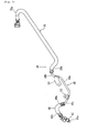
- the fuel hose 46 comprises a thin diameter part 48 cabled so as to pass through the side of the air cleaner 40, and front side and back side elastic hose parts 49, 50 connected to both ends of the thin diameter part 48.
- the thin diameter part 48 is constructed of a metal pipe with an outside diameter of about 8 mm ⁇ folded and formed in a predetermined shape. An inner circumference surface and an outer surface of the metal pipe are respectively coated with predetermined plating treatment. Also, the front side and back side elastic hose parts 49, 50 are constructed of a high-pressure hose having flexibility and an outside diameter about twice that of the thin diameter part 48.
- the back side elastic hose part 50 is cabled so as to extend in forward and backward directions along the lower tank 24a of the fuel tank 22 between the left seat rail 14 and back stay 15.
- An upstream part 50a of the elastic hose part 50 is curved and formed so as to tum from the back side of the tank body 24 to the front side and is connected to the outlet 47b of the fuel pump 47.
- a downstream part 50b extends forward so as to be located in the front side of the lower tank 24a and extends so as to be located from the lower side of the left seat rail 14 to the upper side and is connected to the thin diameter part 48.
- the front side elastic hose part 49 is formed so as to have a generally downward curve and is cabled so as to stride over an upper portion of the throttle body 38 forward and backward and be located upward beyond the left and right side pipes 13b.
- an upstream part 49a is connected to the thin diameter part 48 in the back side of the throttle body 38 and the downstream end 49b is connected to the fuel injection valve 45 in the front side of the throttle body 38.
- This downstream end 49b inclines to the back of the vehicle with respect to an axis line D of the fuel injection valve 45 when viewed from the side of the vehicle. Also, this back inclination portion overlaps with the side pipe 13b when viewed from the side of the vehicle.
- the thin diameter part 48 has a straight part 48a arranged so as to pass through the vicinity of a left wall of the cleaner body 40a, a stand part 48b extending from the vicinity of the back edge of the cleaner body 40a in a backward ascending state following the back end of the straight part 48a, and a bend part 48c extending from the vicinity of the front edge of the cleaner body 40a to the inside in a forward ascending state following the front end of the straight part 48a.
- the front side elastic hose part 49 is connected to the bend part 48c and the back side elastic hose part 50 is connected to the stand part 48b.
- a front bracket 52 and a back bracket 53 are respectively fastened to the bend part 48c and the stand part 48b of the thin diameter part 48 by brazing etc.
- This front bracket 52 is bolted and fixed to a side bracket 13c bonded to an upper surface of the left side pipe 13b and the back bracket 53 is bolted and fixed to a rail bracket 14c bonded to an upper surface of the left seat rail 14.
- the thin diameter part 48 is cabled so that the straight part 48a is close to a left wall of the cleaner body 40a in the inside of the left seat rail 14 and becomes parallel to the left wall and the left seat rail 14. Then, the straight part 48a is cabled so as to be close to the left wall in a direction (vehicle width direction) substantially perpendicular to a die cutting direction (vertical direction) of the cleaner body 40a with respect to the left wall.
- the fuel injection valve 45 is attached to the downstream end of the intake tube 37 so as to incline in an oblique backward direction.
- the fuel injection valve 45 is arranged so that an injection port 45a is oriented to the umbrella back of an intake valve (not shown).
- the fuel injection valve 45 is arranged so as to be located inside space surrounded by the throttle body 38, the cylinder head 5c and the leg shield 19c, specifically, space of the lower side of the side pipes 13b whose the upper side, the left and right sides are covered with the leg shield 19c when viewed from the side of the vehicle.
- the fuel injection valve 45 is arranged between the left and right side pipes 13b in the vicinity of the lower side of a connection part between the left and right side pipes 13b and the main pipe 13a when viewed from the above of the vehicle.
- the intake tube 37 connected to the forward-tilted cylinder head 5c is extended in a generally horizontal direction backward in the lower side of the leg shield 19c and the fuel injection valve 45 is arranged so as to be located inside space surrounded by the cylinder head 5c, the throttle body 38 and the leg shield 19c, specifically, space of the lower side of the side pipes 13b whose the upper side, the left and right sides are covered with the leg shield 19c when viewed from the side of the vehicle, so that the fuel injection valve 45 can be arranged in a region having sufficient space and the fuel injection valve 45 can be arranged so that the injection port 45a is oriented to the umbrella back of an intake valve and thus engine performance can be improved.
- the fuel injection valve 45 can be arranged in empty space formed by the side pipes 13b extending in an oblique upward direction, the cylinder head 5c forward tilted and arranged in a lower portion of the side pipes 13b and the intake tube 37 extending in a generally horizontal direction backward from the cylinder head 5c.
- the fuel injection valve 45 can be arranged so as to be oriented to the umbrella back of the intake valve without heightening an arrangement position of the leg shield 19c and flexibility for an arrangement layout of the fuel injection valve 45 can be increased while ensuring the loading and unloading capability which is an advantage of a motorcycle comprising a stride part.
- the fuel injection valve 45 is arranged between the left and right side pipes 13b in the vicinity of the lower side of a connection part between the left and right side pipes 13b and the main pipe 13a when viewed from the above of the vehicle, so that the fuel injection valve 45 is located between a rigid forward-tilted cylinder and the portion with high rigidity of the vehicle body and damage caused by external force can be prevented.
- the front side elastic hose part 49 of the fuel hose 46 is connected to the fuel injection valve 45 so as to incline to the back of the vehicle with respect to the axis line D of the fuel injection valve 45 and the lower side of the leg shield 19c is cabled backward, so that protrusion to an upper portion of the front side elastic hose part 49 can be reduced and an arrangement position of the leg shield 19c can be prevented from heightening.
- the inclination portion of the fuel hose 46 is overlapped with the side pipes 13b when viewed from the side of the vehicle, so that a bend of a fuel injection valve connection portion of the fuel hose 46 can be reduced.
- the intake tube 37 is extended in a generally horizontal direction backward so as to pass between the cylinder head 5c and the left and right side pipes 13b and the front side elastic hose part 49 is cabled so as to stride over the upper side of the throttle body 38 forward and backward, so that the front side elastic hose part 49 can be cabled effectively using empty space of an upper portion of the throttle body 38.
- the resonator 43 is interposed in the secondary air supply hose 42 for supplying secondary air to an exhaust system and the resonator 43 is arranged in the lower side of the throttle body 38, so that the resonator 43 can be arranged using empty space of the lower side of the throttle body 38. That is, when a carburetor having a float chamber is arranged, it is difficult to secure an arrangement place of the resonator in a lower portion of the float chamber and it is necessary to secure the arrangement place in another place and the periphery of an engine can be formed compactly as compared with such carburetor specifications.
- the portion passing through the vicinity of the side of the air cleaner 40 of the fuel hose 46 for connecting the fuel tank 22 to the fuel injection valve 45 is formed as the thin diameter part 48 with a diameter thinner than that of the front side and back side elastic hose parts 49, 50, so that an increase in a dimension of a vehicle width of the whole vehicle can be avoided without reducing a capacity of the air cleaner 40.
- the portion passing through the vicinity of the air cleaner 40 is formed as the thin diameter part 48, so that it is unnecessary to form a recess groove in the cleaner body 40a while arranging the fuel hose 46 so as to be close in a direction intersecting with a die cutting direction of the cleaner body 40a and a decrease in a capacity of the air cleaner 40 can be avoided.
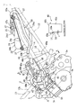
- a relief 40e is formed in the air cleaner body 40a for the close arrangement of the fuel hose 46 as shown in a cross section taken on line a-a of Fig. 3, a dimension of a vehicle width direction of the die cutting direction upstream side portion (lower side portion) from the relief is forced to be decreased by the amount t of the relief 40e and accordingly, the capacity reduces.
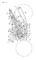
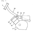
- Figs. 6 and 7 are diagrams describing a motorcycle according to a second embodiment.
- the same numerals as those of Fig. 2 show the same or corresponding parts.
- the motorcycle of the present embodiment is an example in which a frame member 60 connected to a head pipe 3 is arranged so as to be displaced to one side of a vehicle width direction with respect to a vehicle body center line C passing through an axis line of the head pipe 3.
- a leg shield (panel member) for covering the upper side, the left and right sides of the frame member 60 is arranged so as to coincide with the vehicle body center line C.
- an engine 5 is mounted so as to coincide with the vehicle body center line C.
- An intake tube 37 connected to a cylinder head 5c of the engine 5 extends backward so as to be located in the other side of the vehicle width direction with respect to the vehicle body center line C, and is connected to an air cleaner 40.
- an fuel injection valve 45 is arranged so as to be located in the other side of the frame member 60 and be substantially located on the vehicle body center line C when viewed from the above of the vehicle. Also, the fuel injection valve 45 is arranged so as to be located inside space surrounded by the leg shield, a throttle body 38 and the cylinder head 5c and overlap with the frame member 60 when viewed from the side of the vehicle.
- the fuel injection valve 45 is arranged so as to be located in the other side of the frame member 60 arranged so as to be displaced to one side of the vehicle width direction when viewed from the above of the vehicle and is arranged so as to be located inside the space surrounded by the leg shield, the throttle body 38 and the cylinder head 5c and overlap with the frame member 60 when viewed from the side of the vehicle, so that the fuel injection valve 45 can be arranged so as to be oriented to the umbrella back of an intake valve in a region having sufficient space, and an effect substantially similar to that of the embodiment can be obtained.
- a stride part for facilitating a stride of a rider at the time of loading and unloading is formed between a seat and a head pipe for supporting a steering shaft
- an engine is mounted in a lower portion of a panel member constructing the stride part and an intake passage is connected to a cylinder head coupled to a forward-tilted cylinder of the engine and the intake passage extends backward in the lower side of the panel member and a throttle body into which a throttle valve is built is interposed in the vicinity of an engine connection part of the intake passage and a fuel injection valve is disposed so as to be located inside space surrounded by the throttle body, the cylinder head and the panel member when viewed from the side of the vehicle.
- an intake passage connected to a cylinder head in a forward-tilted state is extended backward in the lower side of a panel member and a fuel injection valve is arranged so as to be located inside space surrounded by a throttle body, the cylinder head and the panel member when viewed from the side of the vehicle, so that the fuel injection valve can be arranged in a region having sufficient space.
- the fuel injection valve can be arranged so as to be oriented to the umbrella back of an intake valve and thus engine performance can be improved.
- the panel member constructing a stride part is located higher as the panel member is located in the front side, so that the fuel injection valve can be arranged in empty space between the forward-tilted cylinder head and a front side portion of the panel member.
- the fuel injection valve can be arranged without heightening an arrangement position of the panel member and the fuel injection valve can be arranged so as to be oriented to the umbrella back of the intake valve while ensuring the loading and unloading capability which is an advantage of the motorcycle comprising the stride part.
- a motorcycle in which a stride part for facilitating a stride of a rider at the time of loading and unloading is formed between a seat and a head pipe for supporting a steering shaft, characterized in that an engine is mounted in a lower portion of a panel member constructing the stride part and an intake passage is connected to a cylinder head coupled to a forward-tilted cylinder of said engine and said intake passage extends backward in the lower side of the panel member and a throttle body into which a throttle valve is built is interposed in the vicinity of an engine connection part of said intake passage and a fuel injection valve is disposed so as to be located inside space surrounded by the throttle body, the cylinder head and the panel member when viewed from the side of the vehicle.
- the motorcycle further comprises a frame member which is connected to the head pipe and extends toward a lower portion of the seat in a backward descending state, characterized in that the panel member is formed so as to cover the upper side, the left and right sides of said frame member and the stride part is in a backward descending state and the fuel injection valve is disposed so as to be located inside space surrounded by the frame member, the throttle body and the cylinder head when viewed from the side of the vehicle.
- the frame member has left and right side pipes in at least a part between the head pipe and the seat and the fuel injection valve is arranged between the left and right side pipes when viewed from the above of the vehicle.
- the frame member has one main pipe which is connected to the head pipe and extends to a backward oblique lower portion and left and right side pipes which are connected to the back end of said main pipe and extend to a lower portion of the seat while expanding in a vehicle width direction and the fuel injection valve is arranged between the left and right side pipes in the vicinity of a connection part between said side pipes and the main pipe when viewed from the above of the vehicle.
- a fuel supply hose is connected to the fuel injection valve so as to incline to the back of the vehicle with respect to an axis line of said fuel injection valve and said fuel supply hose extends backward in the lower side of the panel member.
- the fuel supply hose has the portion overlapping with the frame member when viewed from the side of the vehicle.
- the intake passage extends to the back of the vehicle so as to pass between the left and right side pipes.
- the fuel supply hose connected to the fuel injection valve extends backward over the upper side of the throttle body.
- a motorcycle further comprising a frame member which is connected to the head pipe and extends to a lower portion of the seat so as to be displaced to one side of a vehicle width direction in a backward descending state, characterized in that the panel member is formed so as to cover the upper side, the left and right sides of said frame member and the fuel injection valve is located in the other side of the frame member when viewed from the above of the vehicle and is located inside space surrounded by the panel member, the throttle body and the cylinder head when viewed from the side of the vehicle.
- the fuel injection valve is disposed so as to overlap with the frame member when viewed from the side of the vehicle.
- a motorcycle further comprising a secondary air supply system for supplying secondary air to an exhaust system of the engine, characterized in that said secondary air supply system comprises a reed valve opened and closed by pulsation of the exhaust system and a resonator for attenuating a predetermined resonance frequency and said resonator is arranged in the lower side of the throttle body.
- an engine 5 mounted in a lower portion of a leg shield (panel member) 19c constructing a stride part and an intake passage 37 is connected to a forward-tilted cylinder head 5c of the engine 5 and the intake passage 37 extends backward in the lower side of the leg shield 19c and a throttle body 38 into which a throttle valve is built is interposed in the vicinity of an engine connection part of the intake passage 37 and a fuel injection valve 45 is disposed so as to be located inside space surrounded by the throttle body 38, the cylinder head 5c and the leg shield 19c when viewed from the side of the vehicle.
Landscapes
- Engineering & Computer Science (AREA)
- Chemical & Material Sciences (AREA)
- Combustion & Propulsion (AREA)
- Mechanical Engineering (AREA)
- General Engineering & Computer Science (AREA)
- Health & Medical Sciences (AREA)
- Chemical Kinetics & Catalysis (AREA)
- Toxicology (AREA)
- Automatic Cycles, And Cycles In General (AREA)
- Fuel-Injection Apparatus (AREA)
- Seats For Vehicles (AREA)
Abstract
Description
- The present invention relates to a straddle-type vehicle, in particular a motorcycle, having a stride part for facilitating a stride of a rider at the time of loading and unloading between a head pipe and a seat.
- In recent motorcycles, a method for controlling fuel supply by a fuel injection valve according to a run state is being adopted from the standpoint of making improvements etc. in properties of exhaust gas, fuel efficiency or engine output. In the case of arranging such a fuel injection valve, a structure in which an intake passage connected to a cylinder head is extended to the front of a vehicle and also is connected to an air cleaner and the fuel injection valve is substantially perpendicularly stood and arranged in the downstream end of the intake passage is adopted in, for example, Patent Reference 1.
- Patent Reference 1:
JP-A-2002-266724 - By the way, in the conventional motorcycle, a structure in which a fuel injection valve is stood and arranged in the downstream end of an intake passage extending from a cylinder head to the front of the vehicle is adopted. As a result of this, an injection direction of fuel of the fuel injection valve is oriented to a ceiling wall of an intake port and the fuel cannot be injected toward the essentially desirable umbrella back of an intake valve and there is fear that engine performance cannot be offered sufficiently.
- Also, when the fuel injection valve described above is stood and arranged in a motorcycle comprising a backward descending panel member for facilitating loading and unloading of a rider, the need to arrange the panel member in a high position arises in order to avoid interference with the fuel injection valve and it is concerned about a problem of losing the capability of loading and unloading.
- The invention has been implemented in view of the conventional circumstances described above, and an object of the invention is to provide a motorcycle capable of arranging a fuel injection valve so as to be oriented to the umbrella back of an intake valve and thus improving engine performance.
- This objective is solved in an inventive manner by a straddle-type vehicle, in particular motorcycle, comprising a panel member formed between a head pipe and a seat, an engine mounted in a lower portion of the panel member, an intake passage connected to a cylinder head of a cylinder of the engine and extending backwards of the vehicle in the lower side of the panel member, and a throttle body arranged in a vicinity of an engine connection part of the intake passage, wherein a fuel injection valve is arranged inside a space surrounded by the throttle body, the cylinder head and the panel member, when viewed from the side of the vehicle.
- Preferably, the panel member, in particular a leg shield, constitutes a stride part for facilitating a stride of a rider at a time of loading and unloading.
- Further, the cylinder may be arranged forwardly-tilted.
- According to another preferred embodiment, the straddle-type vehicle further comprises a frame member, which is connected to the head pipe and extends toward a lower portion of the seat in a backward descending state, wherein the panel member is formed so as to cover the upper side, the left and right sides of said frame member and a stride part is in a backward descending state and the fuel injection valve is disposed so as to be located inside the space surrounded by the frame member, the throttle body and the cylinder head when viewed from the side of the vehicle.
- Therein, the frame member may have left and right side pipes in at least a part between the head pipe and the seat and the fuel injection valve may be arranged between the left and right side pipes when viewed from the above of the vehicle.
- Moreover, is it preferred if the frame member has one main pipe, which is connected to the head pipe and extends to a backward oblique lower portion and left and right side pipes, which are connected to the back end of said main pipe and extend to a lower portion of the seat while expanding in a vehicle width direction and the fuel injection valve is arranged between the left and right side pipes in the vicinity of a connection part between said side pipes and the main pipe when viewed from the above of the vehicle.
- According to another preferred embodiment, a fuel supply hose is connected to the fuel injection valve so as to incline to the back of the vehicle with respect to an axis line of said fuel injection valve and said fuel supply hose extends backward in the lower side of the panel member.
- Therein, the fuel supply hose may have the portion overlapping with the frame member when viewed from the side of the vehicle.
- In addition, the intake passage may extend to the back of the vehicle so as to pass between the left and right side pipes.
- Further, the fuel supply hose may be connected to the fuel injection valve extends backward over the upper side of the throttle body.
- According to yet another preferred embodiment, the straddle-type vehicle may further comprise a frame member which is connected to the head pipe and extends to a lower portion of the seat so as to be displaced to one side of a vehicle width direction in a backward descending state, wherein the panel member is formed so as to cover the upper side, the left and right sides of said frame member and the fuel injection valve is located in the other side of the frame member when viewed from the above of the vehicle and is located inside space surrounded by the panel member, the throttle body and the cylinder head when viewed from the side of the vehicle.
- Therein, it is further preferable if the fuel injection valve is disposed so as to overlap with the frame member when viewed from the side of the vehicle.
- According to still another preferred embodiment, the straddle-type vehicle may further comprise a secondary air supply system for supplying secondary air to an exhaust system of the engine, characterized in that said secondary air supply system comprises a reed valve opened and closed by pulsation of the exhaust system and a resonator for attenuating a predetermined resonance frequency and said resonator is arranged in the lower side of the throttle body.
- In the following, the present invention is explained in greater detail with respect to several embodiments thereof in conjunction with the accompanying drawings, wherein:
- Fig. 1
- is a side view of a motorcycle according to a first embodiment,
- Fig. 2
- is a side view of a frame member of the motorcycle,
- Fig. 3
- is a side view of a fuel supply device disposed in the frame member,
- Fig. 4
- is a perspective view viewed from the oblique back of the fuel supply device,
- Fig. 5
- is a side view of a fuel hose of the fuel supply device,
- Fig. 6
- is a plan view of a frame member according to a second embodiment, and
- Fig. 7
- is a side view of the frame member.
-
- 1
- MOTORCYCLE
- 3
- HEAD PIPE
- 5
- ENGINE
- 5c
- CYLINDER HEAD
- 7
- SEAT
- 8
- STEERING SHAFT
- 13
- FRAME MEMBER
- 13a
- MAIN PIPE
- 13b
- SIDE PIPE
- 19c
- LEG SHIELD (PANEL MEMBER)
- 22
- FUEL TANK
- 33
- EXHAUST TUBE
- 37
- INTAKE TUBE (INTAKE PASSAGE)
- 38
- THROTTLE BODY
- 40
- AIR CLEANER
- 42
- SECONDARY AIR SUPPLY HOSE
- 43
- RESONATOR
- 45
- FUEL INJECTION VALVE
- 46
- FUEL HOSE
- 60
- FRAME MEMBER
- Embodiments will be described below based on the accompanying drawings.
- Figs. 1 to 5 are diagrams describing a motorcycle according to a first embodiment. In addition, the term "forward and backward, left and right" shown in the present embodiment means "forward and backward, left and right" of the case of being viewed in a state of sitting on a seat.
- In the drawings, numeral 1 shows a motorcycle and this motorcycle comprises a
vehicle body frame 2 of an under bone type, a front fork 4 pivoted by ahead pipe 3 fixed in the front end of thevehicle body frame 2, anengine 5 suspended and supported in the center of thevehicle body frame 2, a rear arm 6 vertically swingably pivoted in the back side of theengine 5 of thevehicle body frame 2, and aseat 7 for two arranged on thevehicle body frame 2. - A
front wheel 10 is axially supported in the lower end of the front fork 4 and arear wheel 11 is axially supported in the back end of the rear arm 6. - A steering
shaft 8 is axially supported in thehead pipe 3 through a bearing (not shown). The front fork 4 is fixed in the lower end of thissteering shaft 8 and asteering handle 9 is fixed in the upper end. - The
vehicle body frame 2 comprises aframe member 13 which is connected to thehead pipe 3 and extends toward a lower portion of theseat 7 in a backward descending state. - The
frame member 13 has onemain pipe 13a which is connected to thehead pipe 3 and extends to a backward oblique lower portion of the vehicle, and one pair of left andright side pipes main pipe 13a and extend to a backward oblique lower portion so as to be located in a lower portion of theseat 7 while expanding to the outside of a width direction of the vehicle. - An axis line of the
main pipe 13a and a center line of the vehicle width direction of the left andright side pipes 13b coincide with a vehicle body center line passing through an axis line of thehead pipe 3. - The front ends of left and right seat rails 14, 14 extending in a backward oblique upper direction of the vehicle are connected to the backs of the left and
right side pipes 13b. Also, the back ends of the left andright side pipes 13b and the back ends of the seat rails 14 are joined by left and right back stays 15, 15. Further, the fronts of the seat rails 14 and the left and right back stays 15 are mutually joined by left and rightlongitudinal pipes - A
rear arm bracket 17 extending downward is connected to the portion to which the back stays 15 of the back ends of the left andright side pipes 13b are connected. The rear arm 6 is supported in thisrear arm bracket 17 by apivot shaft 18. - The
vehicle body frame 2 is covered with avehicle body cover 19. Thisvehicle body cover 19 has ahandle cover 19a for covering the outer circumference of thesteering handle 9, afront cover 19b for covering a front side portion of thehead pipe 3, aleg shield 19c (panel member) for covering the upper side, the left and right sides of theframe member 13 between theseat 7 and thehead pipe 3, and aside cover 19d for covering the downward circumference of theseat 7. - The
leg shield 19c constructs a backward descending stride part which inclines along theframe member 13 in a backward descending state and facilitates a stride of a rider at the time of loading and unloading. - A
fuel tank 22 is arranged in a downward portion of theseat 7 of the left and right seat rails 14 and aglove compartment 23 is arranged in the back side of thefuel tank 22. Abattery box 26 in which a battery and fuse unit (not shown) is received is arranged in the front side of thefuel tank 22. Thebattery box 26 is fixed on the left and right seat rails 14. Also, ahinge part 26a for vertically rotatably supporting theseat 7 is integrally formed in a front wall of thebattery box 26. - The
fuel tank 22 has a structure in which afuel inlet 24d is formed in an upper wall of atank body 24 made by mutually bondingflange parts 24c of alower tank 24a and anupper tank 24b. Thisfuel inlet 24d is openably blocked by afuel cap 25. Thetank body 24 is elastically supported in the left and right seat rails 14 throughelastic bushings 27 attached to each of the corners of theflange parts 24c. - The
engine 5 is a water cooling type four-cycle one-cylinder engine mounted with a cylinder axis line A forward tilted. Thisengine 5 has a general structure in which acylinder block 5b is coupled to an upper mesh surface of acrankcase 5a in which a crankshaft (not shown) is held in a width direction of the vehicle and acylinder head 5c is coupled to an upper mesh surface of thecylinder block 5b and further ahead cover 5d is attached to thecylinder head 5c. Atransmission case part 5e in which a transmission unit (not shown) is held is integrally formed in the back side of thecrankcase 5a. - The
cylinder head 5c is bolted and fixed to themain pipe 13a through left and right frontside suspension brackets 28, and an upper wall of thecrankcase 5a is bolted and fixed to the left andright side pipes 13b through anintermediate suspension bracket 29 and further, the lower end of a back side wall of thetransmission case part 5e is bolted and fixed to alower side bracket 17a of therear arm bracket 17. - A cooling
water pump 30 is arranged in a left wall of thecylinder head 5c. This coolingwater pump 30 is connected to aradiator 31 arranged in the oblique front of theengine 5 through a coolingwater hose 30a. - An exhaust system of the
engine 5 has the following structure. Anexhaust tube 33 in communication with an exhaust port (not shown) is connected to a front side wall of thecylinder head 5c. Thisexhaust tube 33 extends downward from thecylinder head 5c and bends backward therefrom and extends backward through a lower portion of thecrankcase 5a. Amuffler 34 arranged in the right side of therear wheel 11 is connected to the downstream end of theexhaust tube 33. Also, acatalyst 35 is interposed in the upstream side of theexhaust tube 33. - An intake system of the
engine 5 has the following structure. Anintake tube 37 in communication with an intake port (not shown) is connected to a back side wall of thecylinder head 5c. Thisintake tube 37 extends substantially horizontally from thecylinder head 5c to the back of the vehicle and athrottle body 38 into which a throttle valve (not shown) is built is interposed in an intermediate part of theintake tube 37. Also, anair cleaner 40 is connected to the back end of theintake tube 37. Thisair cleaner 40 is set at a predetermined capacity capable of securing the intake amount at the time of the maximum output of theengine 5. - The
air cleaner 40 comprises acleaner body 40a with a bottomed rectangular parallelepiped shape extending in a vertical direction and alid member 40b detachably attached to an upper end opening of thecleaner body 40a. Thecleaner body 40a is manufactured using a metal mold in which a die cutting direction is a vertical direction (direction of an axis line B). That is, in thecleaner body 40a, a dimension of the upper end opening becomes larger than that of the bottom in a width direction and forward and backward directions of the vehicle. - An air filter (not shown) is arranged inside the
cleaner body 40a and theintake tube 37 is connected to a front wall of thecleaner body 40a. Aninlet port 40c is formed in a rear surface of thelid member 40b. - The
air cleaner 40 is arranged with the axis line B forward tilted so as to become substantially parallel to the cylinder axis line A. Thecleaner body 40a is received inside space formed in a connection part between the left andright side pipes cleaner body 40a protrudes upward from the left and right seat rails 14. - A secondary air supply system of the
engine 5 has the following structure. Theair cleaner 40 is communicated and connected to a downstream side portion of thecatalyst 35 of theexhaust tube 33 by a secondaryair supply hose 42 for supplying secondary air to the inside of theexhaust tube 33; - A reed valve (not shown) opened and closed by pulsation of the exhaust system and a
resonator 43 for attenuating a predetermined resonance frequency in the upstream side of the reed valve are interposed in the secondaryair supply hose 42. The reed valve is arranged in the right side of thecylinder block 5b and theresonator 43 is arranged in a left lower portion of thethrottle body 38 and is mounted and fixed in thethrottle body 38. - A fuel supply device is disposed in the
engine 5. This fuel supply device comprises thefuel tank 22 arranged in the back of theair cleaner 40, afuel injection valve 45 which is arranged in the front of theair cleaner 40 and is connected to theengine 5, afuel hose 46 for making connection between thefuel injection valve 45 and thefuel tank 22, and afuel pump 47 for pressurizing fuel of the inside of thefuel tank 22 and supplying the fuel to thefuel injection valve 45. - The
fuel pump 47 is received and arranged inside thefuel tank 22. An inlet (not shown) of thefuel pump 47 is located in the bottom of the tank and anoutlet 47b protrudes backward from an upper wall of thetank body 24. - The
fuel hose 46 is connected to theoutlet 47b of thefuel pump 47 and extends forward through the left side of thefuel tank 22 from theoutlet 47b and is connected to thefuel injection valve 45 through the left side of theair cleaner 40, and specifically has the following structure. - The
fuel hose 46 comprises athin diameter part 48 cabled so as to pass through the side of theair cleaner 40, and front side and back sideelastic hose parts thin diameter part 48. - The
thin diameter part 48 is constructed of a metal pipe with an outside diameter of about 8 mmφ folded and formed in a predetermined shape. An inner circumference surface and an outer surface of the metal pipe are respectively coated with predetermined plating treatment. Also, the front side and back sideelastic hose parts thin diameter part 48. - The back side
elastic hose part 50 is cabled so as to extend in forward and backward directions along thelower tank 24a of thefuel tank 22 between theleft seat rail 14 and back stay 15. Anupstream part 50a of theelastic hose part 50 is curved and formed so as to tum from the back side of thetank body 24 to the front side and is connected to theoutlet 47b of thefuel pump 47. Also, adownstream part 50b extends forward so as to be located in the front side of thelower tank 24a and extends so as to be located from the lower side of theleft seat rail 14 to the upper side and is connected to thethin diameter part 48. - The front side
elastic hose part 49 is formed so as to have a generally downward curve and is cabled so as to stride over an upper portion of thethrottle body 38 forward and backward and be located upward beyond the left andright side pipes 13b. In the front sideelastic hose part 49, anupstream part 49a is connected to thethin diameter part 48 in the back side of thethrottle body 38 and thedownstream end 49b is connected to thefuel injection valve 45 in the front side of thethrottle body 38. Thisdownstream end 49b inclines to the back of the vehicle with respect to an axis line D of thefuel injection valve 45 when viewed from the side of the vehicle. Also, this back inclination portion overlaps with theside pipe 13b when viewed from the side of the vehicle. - The
thin diameter part 48 has astraight part 48a arranged so as to pass through the vicinity of a left wall of thecleaner body 40a, astand part 48b extending from the vicinity of the back edge of thecleaner body 40a in a backward ascending state following the back end of thestraight part 48a, and abend part 48c extending from the vicinity of the front edge of thecleaner body 40a to the inside in a forward ascending state following the front end of thestraight part 48a. The front sideelastic hose part 49 is connected to thebend part 48c and the back sideelastic hose part 50 is connected to thestand part 48b. - A
front bracket 52 and aback bracket 53 are respectively fastened to thebend part 48c and thestand part 48b of thethin diameter part 48 by brazing etc. Thisfront bracket 52 is bolted and fixed to a side bracket 13c bonded to an upper surface of theleft side pipe 13b and theback bracket 53 is bolted and fixed to arail bracket 14c bonded to an upper surface of theleft seat rail 14. - The
thin diameter part 48 is cabled so that thestraight part 48a is close to a left wall of thecleaner body 40a in the inside of theleft seat rail 14 and becomes parallel to the left wall and theleft seat rail 14. Then, thestraight part 48a is cabled so as to be close to the left wall in a direction (vehicle width direction) substantially perpendicular to a die cutting direction (vertical direction) of thecleaner body 40a with respect to the left wall. - The
fuel injection valve 45 is attached to the downstream end of theintake tube 37 so as to incline in an oblique backward direction. Thefuel injection valve 45 is arranged so that aninjection port 45a is oriented to the umbrella back of an intake valve (not shown). - The
fuel injection valve 45 is arranged so as to be located inside space surrounded by thethrottle body 38, thecylinder head 5c and theleg shield 19c, specifically, space of the lower side of theside pipes 13b whose the upper side, the left and right sides are covered with theleg shield 19c when viewed from the side of the vehicle. - Also, the
fuel injection valve 45 is arranged between the left andright side pipes 13b in the vicinity of the lower side of a connection part between the left andright side pipes 13b and themain pipe 13a when viewed from the above of the vehicle. - According to the embodiment, the
intake tube 37 connected to the forward-tiltedcylinder head 5c is extended in a generally horizontal direction backward in the lower side of theleg shield 19c and thefuel injection valve 45 is arranged so as to be located inside space surrounded by thecylinder head 5c, thethrottle body 38 and theleg shield 19c, specifically, space of the lower side of theside pipes 13b whose the upper side, the left and right sides are covered with theleg shield 19c when viewed from the side of the vehicle, so that thefuel injection valve 45 can be arranged in a region having sufficient space and thefuel injection valve 45 can be arranged so that theinjection port 45a is oriented to the umbrella back of an intake valve and thus engine performance can be improved. - That is, the
fuel injection valve 45 can be arranged in empty space formed by theside pipes 13b extending in an oblique upward direction, thecylinder head 5c forward tilted and arranged in a lower portion of theside pipes 13b and theintake tube 37 extending in a generally horizontal direction backward from thecylinder head 5c. As a result of that, thefuel injection valve 45 can be arranged so as to be oriented to the umbrella back of the intake valve without heightening an arrangement position of theleg shield 19c and flexibility for an arrangement layout of thefuel injection valve 45 can be increased while ensuring the loading and unloading capability which is an advantage of a motorcycle comprising a stride part. - In the embodiment, the
fuel injection valve 45 is arranged between the left andright side pipes 13b in the vicinity of the lower side of a connection part between the left andright side pipes 13b and themain pipe 13a when viewed from the above of the vehicle, so that thefuel injection valve 45 is located between a rigid forward-tilted cylinder and the portion with high rigidity of the vehicle body and damage caused by external force can be prevented. - In the embodiment, the front side
elastic hose part 49 of thefuel hose 46 is connected to thefuel injection valve 45 so as to incline to the back of the vehicle with respect to the axis line D of thefuel injection valve 45 and the lower side of theleg shield 19c is cabled backward, so that protrusion to an upper portion of the front sideelastic hose part 49 can be reduced and an arrangement position of theleg shield 19c can be prevented from heightening. Also, the inclination portion of thefuel hose 46 is overlapped with theside pipes 13b when viewed from the side of the vehicle, so that a bend of a fuel injection valve connection portion of thefuel hose 46 can be reduced. - In the embodiment, the
intake tube 37 is extended in a generally horizontal direction backward so as to pass between thecylinder head 5c and the left andright side pipes 13b and the front sideelastic hose part 49 is cabled so as to stride over the upper side of thethrottle body 38 forward and backward, so that the front sideelastic hose part 49 can be cabled effectively using empty space of an upper portion of thethrottle body 38. - In the embodiment, the
resonator 43 is interposed in the secondaryair supply hose 42 for supplying secondary air to an exhaust system and theresonator 43 is arranged in the lower side of thethrottle body 38, so that theresonator 43 can be arranged using empty space of the lower side of thethrottle body 38. That is, when a carburetor having a float chamber is arranged, it is difficult to secure an arrangement place of the resonator in a lower portion of the float chamber and it is necessary to secure the arrangement place in another place and the periphery of an engine can be formed compactly as compared with such carburetor specifications. - According to the embodiment, the portion passing through the vicinity of the side of the
air cleaner 40 of thefuel hose 46 for connecting thefuel tank 22 to thefuel injection valve 45 is formed as thethin diameter part 48 with a diameter thinner than that of the front side and back sideelastic hose parts air cleaner 40. - Also, the portion passing through the vicinity of the
air cleaner 40 is formed as thethin diameter part 48, so that it is unnecessary to form a recess groove in thecleaner body 40a while arranging thefuel hose 46 so as to be close in a direction intersecting with a die cutting direction of thecleaner body 40a and a decrease in a capacity of theair cleaner 40 can be avoided. - When a
relief 40e is formed in the aircleaner body 40a for the close arrangement of thefuel hose 46 as shown in a cross section taken on line a-a of Fig. 3, a dimension of a vehicle width direction of the die cutting direction upstream side portion (lower side portion) from the relief is forced to be decreased by the amount t of therelief 40e and accordingly, the capacity reduces. - Figs. 6 and 7 are diagrams describing a motorcycle according to a second embodiment. In the diagrams, the same numerals as those of Fig. 2 show the same or corresponding parts.
- The motorcycle of the present embodiment is an example in which a
frame member 60 connected to ahead pipe 3 is arranged so as to be displaced to one side of a vehicle width direction with respect to a vehicle body center line C passing through an axis line of thehead pipe 3. - In this
frame member 60, a leg shield (panel member) (not shown) for covering the upper side, the left and right sides of theframe member 60 is arranged so as to coincide with the vehicle body center line C. - In the lower side of the
frame member 60, anengine 5 is mounted so as to coincide with the vehicle body center line C.An intake tube 37 connected to acylinder head 5c of theengine 5 extends backward so as to be located in the other side of the vehicle width direction with respect to the vehicle body center line C, and is connected to anair cleaner 40. - Then, an
fuel injection valve 45 is arranged so as to be located in the other side of theframe member 60 and be substantially located on the vehicle body center line C when viewed from the above of the vehicle. Also, thefuel injection valve 45 is arranged so as to be located inside space surrounded by the leg shield, athrottle body 38 and thecylinder head 5c and overlap with theframe member 60 when viewed from the side of the vehicle. - In the embodiment, the
fuel injection valve 45 is arranged so as to be located in the other side of theframe member 60 arranged so as to be displaced to one side of the vehicle width direction when viewed from the above of the vehicle and is arranged so as to be located inside the space surrounded by the leg shield, thethrottle body 38 and thecylinder head 5c and overlap with theframe member 60 when viewed from the side of the vehicle, so that thefuel injection valve 45 can be arranged so as to be oriented to the umbrella back of an intake valve in a region having sufficient space, and an effect substantially similar to that of the embodiment can be obtained. - The description above discloses (amongst others) an embodiment of a motorcycle, in which a stride part for facilitating a stride of a rider at the time of loading and unloading is formed between a seat and a head pipe for supporting a steering shaft, an engine is mounted in a lower portion of a panel member constructing the stride part and an intake passage is connected to a cylinder head coupled to a forward-tilted cylinder of the engine and the intake passage extends backward in the lower side of the panel member and a throttle body into which a throttle valve is built is interposed in the vicinity of an engine connection part of the intake passage and a fuel injection valve is disposed so as to be located inside space surrounded by the throttle body, the cylinder head and the panel member when viewed from the side of the vehicle.
- In accordance with a motorcycle according to this preferred embodiment, an intake passage connected to a cylinder head in a forward-tilted state is extended backward in the lower side of a panel member and a fuel injection valve is arranged so as to be located inside space surrounded by a throttle body, the cylinder head and the panel member when viewed from the side of the vehicle, so that the fuel injection valve can be arranged in a region having sufficient space. As a result of that, the fuel injection valve can be arranged so as to be oriented to the umbrella back of an intake valve and thus engine performance can be improved. That is, the panel member constructing a stride part is located higher as the panel member is located in the front side, so that the fuel injection valve can be arranged in empty space between the forward-tilted cylinder head and a front side portion of the panel member. As a result of that, the fuel injection valve can be arranged without heightening an arrangement position of the panel member and the fuel injection valve can be arranged so as to be oriented to the umbrella back of the intake valve while ensuring the loading and unloading capability which is an advantage of the motorcycle comprising the stride part.
- The description above further discloses, as a preferred first aspect, a motorcycle in which a stride part for facilitating a stride of a rider at the time of loading and unloading is formed between a seat and a head pipe for supporting a steering shaft, characterized in that an engine is mounted in a lower portion of a panel member constructing the stride part and an intake passage is connected to a cylinder head coupled to a forward-tilted cylinder of said engine and said intake passage extends backward in the lower side of the panel member and a throttle body into which a throttle valve is built is interposed in the vicinity of an engine connection part of said intake passage and a fuel injection valve is disposed so as to be located inside space surrounded by the throttle body, the cylinder head and the panel member when viewed from the side of the vehicle.
- Further, according to a preferred second aspect, the motorcycle further comprises a frame member which is connected to the head pipe and extends toward a lower portion of the seat in a backward descending state, characterized in that the panel member is formed so as to cover the upper side, the left and right sides of said frame member and the stride part is in a backward descending state and the fuel injection valve is disposed so as to be located inside space surrounded by the frame member, the throttle body and the cylinder head when viewed from the side of the vehicle.
- Further, according to a preferred third aspect, the frame member has left and right side pipes in at least a part between the head pipe and the seat and the fuel injection valve is arranged between the left and right side pipes when viewed from the above of the vehicle.
- Further, according to a preferred fourth aspect, the frame member has one main pipe which is connected to the head pipe and extends to a backward oblique lower portion and left and right side pipes which are connected to the back end of said main pipe and extend to a lower portion of the seat while expanding in a vehicle width direction and the fuel injection valve is arranged between the left and right side pipes in the vicinity of a connection part between said side pipes and the main pipe when viewed from the above of the vehicle.
- Further, according to a preferred fifth aspect, a fuel supply hose is connected to the fuel injection valve so as to incline to the back of the vehicle with respect to an axis line of said fuel injection valve and said fuel supply hose extends backward in the lower side of the panel member.
- Further, according to a preferred sixth aspect, the fuel supply hose has the portion overlapping with the frame member when viewed from the side of the vehicle.
- In addition, according to a preferred seventh aspect, the intake passage extends to the back of the vehicle so as to pass between the left and right side pipes.
- In addition, according to a preferred eighth aspect, the fuel supply hose connected to the fuel injection valve extends backward over the upper side of the throttle body.
- Further, according to a preferred ninth aspect, there is provided a motorcycle further comprising a frame member which is connected to the head pipe and extends to a lower portion of the seat so as to be displaced to one side of a vehicle width direction in a backward descending state, characterized in that the panel member is formed so as to cover the upper side, the left and right sides of said frame member and the fuel injection valve is located in the other side of the frame member when viewed from the above of the vehicle and is located inside space surrounded by the panel member, the throttle body and the cylinder head when viewed from the side of the vehicle.
- Further, according to a preferred tenth aspect, the fuel injection valve is disposed so as to overlap with the frame member when viewed from the side of the vehicle.
- Likewise, according to a preferred eleventh aspect, there is provided a motorcycle further comprising a secondary air supply system for supplying secondary air to an exhaust system of the engine, characterized in that said secondary air supply system comprises a reed valve opened and closed by pulsation of the exhaust system and a resonator for attenuating a predetermined resonance frequency and said resonator is arranged in the lower side of the throttle body.
- Moreover, according to a particularly preferred embodiment, in order to provide a motorcycle capable of arranging a fuel injection valve so as to be oriented to the umbrella back of an intake valve and thus improving engine performance, there is disclosed an
engine 5 mounted in a lower portion of a leg shield (panel member) 19c constructing a stride part and anintake passage 37 is connected to a forward-tiltedcylinder head 5c of theengine 5 and theintake passage 37 extends backward in the lower side of theleg shield 19c and athrottle body 38 into which a throttle valve is built is interposed in the vicinity of an engine connection part of theintake passage 37 and afuel injection valve 45 is disposed so as to be located inside space surrounded by thethrottle body 38, thecylinder head 5c and theleg shield 19c when viewed from the side of the vehicle.
Claims (13)
- Straddle-type vehicle, in particular motorcycle, comprising
a panel member formed between a head pipe and a seat,
an engine mounted in a lower portion of the panel member,
an intake passage connected to a cylinder head of a cylinder of the engine and extending backwards of the vehicle in the lower side of the panel member,
and a throttle body arranged in a vicinity of an engine connection part of the intake passage,
wherein a fuel injection valve is arranged inside a space surrounded by the throttle body, the cylinder head and the panel member, when viewed from the side of the vehicle. - Straddle-type vehicle according to claim 1, wherein the panel member, in particular a leg shield, constitutes a stride part for facilitating a stride of a rider at a time of loading and unloading.
- Straddle-type vehicle according to claim 1 or 2, wherein the cylinder is arranged forwardly-tilted.
- Straddle-type vehicle according to one of the claims 1 to 3, further comprising a frame member, which is connected to the head pipe and extends toward a lower portion of the seat in a backward descending state, wherein the panel member is formed so as to cover the upper side, the left and right sides of said frame member and a stride part is in a backward descending state and the fuel injection valve is disposed so as to be located inside the space surrounded by the frame member, the throttle body and the cylinder head when viewed from the side of the vehicle.
- Straddle-type vehicle according to claim 4, wherein the frame member has left and right side pipes in at least a part between the head pipe and the seat and the fuel injection valve is arranged between the left and right side pipes when viewed from the above of the vehicle.
- Straddle-type vehicle according to claim 5, wherein the frame member has one main pipe, which is connected to the head pipe and extends to a backward oblique lower portion and left and right side pipes, which are connected to the back end of said main pipe and extend to a lower portion of the seat while expanding in a vehicle width direction and the fuel injection valve is arranged between the left and right side pipes in the vicinity of a connection part between said side pipes and the main pipe when viewed from the above of the vehicle.
- Straddle-type vehicle according to one of the claims 1 to 6, wherein a fuel supply hose is connected to the fuel injection valve so as to incline to the back of the vehicle with respect to an axis line of said fuel injection valve and said fuel supply hose extends backward in the lower side of the panel member.
- Straddle-type vehicle according to claim 7, wherein the fuel supply hose has the portion overlapping with the frame member when viewed from the side of the vehicle.
- Straddle-type vehicle according to one of the claims 5 to 8, wherein the intake passage extends to the back of the vehicle so as to pass between the left and right side pipes.
- Straddle-type vehicle according to claim 8 or 9, wherein the fuel supply hose connected to the fuel injection valve extends backward over the upper side of the throttle body.
- Straddle-type vehicle according to one of the claims 1 to 3, further comprising a frame member which is connected to the head pipe and extends to a lower portion of the seat so as to be displaced to one side of a vehicle width direction in a backward descending state, wherein the panel member is formed so as to cover the upper side, the left and right sides of said frame member and the fuel injection valve is located in the other side of the frame member when viewed from the above of the vehicle and is located inside space surrounded by the panel member, the throttle body and the cylinder head when viewed from the side of the vehicle.
- Straddle-type vehicle according to claim 11, wherein the fuel injection valve is disposed so as to overlap with the frame member when viewed from the side of the vehicle.
- Straddle-type vehicle according to one of the claims 1 to 12, further comprising a secondary air supply system for supplying secondary air to an exhaust system of the engine, characterized in that said secondary air supply system comprises a reed valve opened and closed by pulsation of the exhaust system and a resonator for attenuating a predetermined resonance frequency and said resonator is arranged in the lower side of the throttle body.
Applications Claiming Priority (1)
| Application Number | Priority Date | Filing Date | Title |
|---|---|---|---|
| JP2005302070A JP2007107505A (en) | 2005-10-17 | 2005-10-17 | Motorcycle |
Publications (2)
| Publication Number | Publication Date |
|---|---|
| EP1775207A1 true EP1775207A1 (en) | 2007-04-18 |
| EP1775207B1 EP1775207B1 (en) | 2010-07-28 |
Family
ID=37603196
Family Applications (1)
| Application Number | Title | Priority Date | Filing Date |
|---|---|---|---|
| EP06021652A Active EP1775207B1 (en) | 2005-10-17 | 2006-10-16 | Straddle-type vehicle |
Country Status (6)
| Country | Link |
|---|---|
| US (1) | US7703569B2 (en) |
| EP (1) | EP1775207B1 (en) |
| JP (1) | JP2007107505A (en) |
| CN (1) | CN100475637C (en) |
| AT (1) | ATE475583T1 (en) |
| DE (1) | DE602006015753D1 (en) |
Cited By (2)
| Publication number | Priority date | Publication date | Assignee | Title |
|---|---|---|---|---|
| EP2025588A3 (en) * | 2007-07-19 | 2009-06-03 | Yamaha Hatsudoki Kabushiki Kaisha | Frame of motorcycle and motorcycle |
| EP2639146A1 (en) * | 2012-03-15 | 2013-09-18 | Yamaha Hatsudoki Kabushiki Kaisha | Straddle-type vehicle |
Families Citing this family (13)
| Publication number | Priority date | Publication date | Assignee | Title |
|---|---|---|---|---|
| JP2009215997A (en) * | 2008-03-11 | 2009-09-24 | Yamaha Motor Co Ltd | Saddle riding type vehicle |
| US7861816B2 (en) * | 2008-10-21 | 2011-01-04 | Honda Motor Company, Ltd. | Motorcycle configured to facilitate access to engine cylinder |
| JP5520623B2 (en) * | 2010-01-29 | 2014-06-11 | 本田技研工業株式会社 | Fuel supply device |
| TWI435814B (en) * | 2011-10-26 | 2014-05-01 | Kwang Yang Motor Co | The storage structure of the two - wheeled battery |
| CN103121487B (en) * | 2011-11-18 | 2016-05-11 | 光阳工业股份有限公司 | Two-wheeler battery storage structure |
| US8657050B2 (en) * | 2012-05-17 | 2014-02-25 | Honda Motor Co., Ltd. | Saddle-ride type vehicle |
| JP6122732B2 (en) * | 2013-08-09 | 2017-04-26 | 本田技研工業株式会社 | Saddle riding vehicle |
| JP5932865B2 (en) * | 2013-09-30 | 2016-06-08 | 本田技研工業株式会社 | Saddle riding |
| JP5775560B2 (en) * | 2013-12-06 | 2015-09-09 | 本田技研工業株式会社 | Saddle riding |
| CN105836016B (en) * | 2015-01-16 | 2019-10-18 | 光阳工业股份有限公司 | Motorcycle with a motorcycle body |
| CN109563780B (en) * | 2016-08-10 | 2021-10-22 | 本田技研工业株式会社 | straddle vehicle |
| JP6448692B2 (en) * | 2017-03-16 | 2019-01-09 | 本田技研工業株式会社 | On-vehicle structure of air-cooled internal combustion engine |
| CN112814802B (en) * | 2020-11-16 | 2023-03-24 | 浙江春风动力股份有限公司 | Low-emission motorcycle |
Citations (8)
| Publication number | Priority date | Publication date | Assignee | Title |
|---|---|---|---|---|
| FR2664227A1 (en) * | 1990-07-03 | 1992-01-10 | Cagiva Motor | Motor cycle frame |
| JPH11336538A (en) * | 1998-05-28 | 1999-12-07 | Yamaha Motor Co Ltd | Reed valve mounting structure |
| EP1186526A2 (en) * | 2000-09-08 | 2002-03-13 | Honda Giken Kogyo Kabushiki Kaisha | Engine mounting structure in motorcycle |
| JP2002266724A (en) * | 2001-03-08 | 2002-09-18 | Honda Motor Co Ltd | Fuel piping structure of fuel injection engine |
| EP1319591A1 (en) * | 2001-12-14 | 2003-06-18 | Yamaha Hatsudoki Kabushiki Kaisha | Straddle type of vehicle |
| US20040171449A1 (en) * | 2002-04-08 | 2004-09-02 | Akifumi Oishi | Engine |
| EP1526024A2 (en) * | 2003-10-23 | 2005-04-27 | Yamaha Hatsudoki Kabushiki Kaisha | Secondary air supply device and motorcycle comprising same |
| US20060066092A1 (en) * | 2004-09-24 | 2006-03-30 | Yamaha Hatsudoki Kabushiki Kaisha | Straddle type vehicle |
Family Cites Families (6)
| Publication number | Priority date | Publication date | Assignee | Title |
|---|---|---|---|---|
| JP3875417B2 (en) * | 1998-11-25 | 2007-01-31 | 本田技研工業株式会社 | Fuel injection device for vehicle engine |
| JP4057384B2 (en) * | 2002-09-26 | 2008-03-05 | 本田技研工業株式会社 | Engine mounting structure for low floor vehicles |
| JP2004324426A (en) * | 2003-04-21 | 2004-11-18 | Keihin Corp | Intake device and control device for internal combustion engine |
| JP4381246B2 (en) * | 2004-07-21 | 2009-12-09 | 本田技研工業株式会社 | Control device for in-vehicle internal combustion engine |
| JP4464243B2 (en) * | 2004-08-25 | 2010-05-19 | 川崎重工業株式会社 | Engine intake system |
| US7526915B2 (en) * | 2005-08-05 | 2009-05-05 | Yamaha Hatsudoki Kabushiki Kaisha | Single cylinder engine with ternary catalyst in exhaust passage and vehicle provided with same |
-
2005
- 2005-10-17 JP JP2005302070A patent/JP2007107505A/en not_active Withdrawn
-
2006
- 2006-10-16 EP EP06021652A patent/EP1775207B1/en active Active
- 2006-10-16 US US11/549,866 patent/US7703569B2/en not_active Expired - Fee Related
- 2006-10-16 AT AT06021652T patent/ATE475583T1/en not_active IP Right Cessation
- 2006-10-16 DE DE602006015753T patent/DE602006015753D1/en active Active
- 2006-10-17 CN CNB2006101363718A patent/CN100475637C/en active Active
Patent Citations (8)
| Publication number | Priority date | Publication date | Assignee | Title |
|---|---|---|---|---|
| FR2664227A1 (en) * | 1990-07-03 | 1992-01-10 | Cagiva Motor | Motor cycle frame |
| JPH11336538A (en) * | 1998-05-28 | 1999-12-07 | Yamaha Motor Co Ltd | Reed valve mounting structure |
| EP1186526A2 (en) * | 2000-09-08 | 2002-03-13 | Honda Giken Kogyo Kabushiki Kaisha | Engine mounting structure in motorcycle |
| JP2002266724A (en) * | 2001-03-08 | 2002-09-18 | Honda Motor Co Ltd | Fuel piping structure of fuel injection engine |
| EP1319591A1 (en) * | 2001-12-14 | 2003-06-18 | Yamaha Hatsudoki Kabushiki Kaisha | Straddle type of vehicle |
| US20040171449A1 (en) * | 2002-04-08 | 2004-09-02 | Akifumi Oishi | Engine |
| EP1526024A2 (en) * | 2003-10-23 | 2005-04-27 | Yamaha Hatsudoki Kabushiki Kaisha | Secondary air supply device and motorcycle comprising same |
| US20060066092A1 (en) * | 2004-09-24 | 2006-03-30 | Yamaha Hatsudoki Kabushiki Kaisha | Straddle type vehicle |
Cited By (2)
| Publication number | Priority date | Publication date | Assignee | Title |
|---|---|---|---|---|
| EP2025588A3 (en) * | 2007-07-19 | 2009-06-03 | Yamaha Hatsudoki Kabushiki Kaisha | Frame of motorcycle and motorcycle |
| EP2639146A1 (en) * | 2012-03-15 | 2013-09-18 | Yamaha Hatsudoki Kabushiki Kaisha | Straddle-type vehicle |
Also Published As
| Publication number | Publication date |
|---|---|
| CN100475637C (en) | 2009-04-08 |
| US7703569B2 (en) | 2010-04-27 |
| DE602006015753D1 (en) | 2010-09-09 |
| JP2007107505A (en) | 2007-04-26 |
| CN1951754A (en) | 2007-04-25 |
| EP1775207B1 (en) | 2010-07-28 |
| US20070089921A1 (en) | 2007-04-26 |
| ATE475583T1 (en) | 2010-08-15 |
Similar Documents
| Publication | Publication Date | Title |
|---|---|---|
| EP1775207B1 (en) | Straddle-type vehicle | |
| JP6043353B2 (en) | Saddle-type vehicle engine | |
| JP5798491B2 (en) | Motorcycle with turbocharger | |
| EP2933448B1 (en) | Saddled vehicle | |
| JP4555413B2 (en) | Fuel injection device for backbone type motorcycle | |
| JP3075806B2 (en) | Arrangement structure of vehicle fuel pump | |
| JP3836665B2 (en) | Motorcycle | |
| JPH1122572A (en) | Resonator structure of internal combustion engine | |
| JP4785557B2 (en) | Exhaust structure of motorcycle | |
| JP4244311B2 (en) | Fuel tank structure in motorcycles | |
| JP4901619B2 (en) | Breather device for internal combustion engine | |
| JP4108381B2 (en) | Motorcycle exhaust system | |
| JP2007099143A (en) | FUEL SUPPLY DEVICE AND MOTORCYCLE HAVING THE FUEL SUPPLY DEVICE | |
| JP2007008357A (en) | Air intake structure for motorcycles | |
| JP4226257B2 (en) | Fuel pump arrangement structure for motorcycles | |
| JP3786066B2 (en) | Engine intake system | |
| JP2008031934A (en) | Intake device for motorcycle | |
| JP2006291807A (en) | Engine and vehicle | |
| JP2009226989A (en) | Fuel piping structure of motorcycle | |
| JP2011063045A (en) | Motorcycle | |
| JP4603405B2 (en) | Saddle riding vehicle | |
| JP4494679B2 (en) | Intake device for motorcycle | |
| JP2020200782A (en) | Intake device of internal combustion engine with supercharger | |
| JP4673870B2 (en) | Fuel injection device for backbone type motorcycle | |
| JP2008261340A (en) | Fuel injection device for backbone type motorcycle |
Legal Events
| Date | Code | Title | Description |
|---|---|---|---|
| PUAI | Public reference made under article 153(3) epc to a published international application that has entered the european phase |
Free format text: ORIGINAL CODE: 0009012 |
|
| 17P | Request for examination filed |
Effective date: 20070223 |
|
| AK | Designated contracting states |
Kind code of ref document: A1 Designated state(s): AT BE BG CH CY CZ DE DK EE ES FI FR GB GR HU IE IS IT LI LT LU LV MC NL PL PT RO SE SI SK TR |
|
| AX | Request for extension of the european patent |
Extension state: AL BA HR MK YU |
|
| 17Q | First examination report despatched |
Effective date: 20070525 |
|
| AKX | Designation fees paid |
Designated state(s): AT BE BG CH CY CZ DE DK EE ES FI FR GB GR HU IE IS IT LI LT LU LV MC NL PL PT RO SE SI SK TR |
|
| GRAP | Despatch of communication of intention to grant a patent |
Free format text: ORIGINAL CODE: EPIDOSNIGR1 |
|
| GRAS | Grant fee paid |
Free format text: ORIGINAL CODE: EPIDOSNIGR3 |
|
| GRAA | (expected) grant |
Free format text: ORIGINAL CODE: 0009210 |
|
| AK | Designated contracting states |
Kind code of ref document: B1 Designated state(s): AT BE BG CH CY CZ DE DK EE ES FI FR GB GR HU IE IS IT LI LT LU LV MC NL PL PT RO SE SI SK TR |
|
| REG | Reference to a national code |
Ref country code: GB Ref legal event code: FG4D |
|
| REG | Reference to a national code |
Ref country code: CH Ref legal event code: EP |
|
| REG | Reference to a national code |
Ref country code: IE Ref legal event code: FG4D |
|
| REF | Corresponds to: |
Ref document number: 602006015753 Country of ref document: DE Date of ref document: 20100909 Kind code of ref document: P |
|
| REG | Reference to a national code |
Ref country code: NL Ref legal event code: VDEP Effective date: 20100728 |
|
| LTIE | Lt: invalidation of european patent or patent extension |
Effective date: 20100728 |
|
| PG25 | Lapsed in a contracting state [announced via postgrant information from national office to epo] |
Ref country code: FI Free format text: LAPSE BECAUSE OF FAILURE TO SUBMIT A TRANSLATION OF THE DESCRIPTION OR TO PAY THE FEE WITHIN THE PRESCRIBED TIME-LIMIT Effective date: 20100728 Ref country code: NL Free format text: LAPSE BECAUSE OF FAILURE TO SUBMIT A TRANSLATION OF THE DESCRIPTION OR TO PAY THE FEE WITHIN THE PRESCRIBED TIME-LIMIT Effective date: 20100728 Ref country code: LT Free format text: LAPSE BECAUSE OF FAILURE TO SUBMIT A TRANSLATION OF THE DESCRIPTION OR TO PAY THE FEE WITHIN THE PRESCRIBED TIME-LIMIT Effective date: 20100728 Ref country code: AT Free format text: LAPSE BECAUSE OF FAILURE TO SUBMIT A TRANSLATION OF THE DESCRIPTION OR TO PAY THE FEE WITHIN THE PRESCRIBED TIME-LIMIT Effective date: 20100728 |
|
| PG25 | Lapsed in a contracting state [announced via postgrant information from national office to epo] |
Ref country code: SI Free format text: LAPSE BECAUSE OF FAILURE TO SUBMIT A TRANSLATION OF THE DESCRIPTION OR TO PAY THE FEE WITHIN THE PRESCRIBED TIME-LIMIT Effective date: 20100728 Ref country code: PL Free format text: LAPSE BECAUSE OF FAILURE TO SUBMIT A TRANSLATION OF THE DESCRIPTION OR TO PAY THE FEE WITHIN THE PRESCRIBED TIME-LIMIT Effective date: 20100728 Ref country code: CY Free format text: LAPSE BECAUSE OF FAILURE TO SUBMIT A TRANSLATION OF THE DESCRIPTION OR TO PAY THE FEE WITHIN THE PRESCRIBED TIME-LIMIT Effective date: 20100728 Ref country code: IS Free format text: LAPSE BECAUSE OF FAILURE TO SUBMIT A TRANSLATION OF THE DESCRIPTION OR TO PAY THE FEE WITHIN THE PRESCRIBED TIME-LIMIT Effective date: 20101128 Ref country code: BG Free format text: LAPSE BECAUSE OF FAILURE TO SUBMIT A TRANSLATION OF THE DESCRIPTION OR TO PAY THE FEE WITHIN THE PRESCRIBED TIME-LIMIT Effective date: 20101028 Ref country code: PT Free format text: LAPSE BECAUSE OF FAILURE TO SUBMIT A TRANSLATION OF THE DESCRIPTION OR TO PAY THE FEE WITHIN THE PRESCRIBED TIME-LIMIT Effective date: 20101129 |
|
| PG25 | Lapsed in a contracting state [announced via postgrant information from national office to epo] |
Ref country code: SE Free format text: LAPSE BECAUSE OF FAILURE TO SUBMIT A TRANSLATION OF THE DESCRIPTION OR TO PAY THE FEE WITHIN THE PRESCRIBED TIME-LIMIT Effective date: 20100728 Ref country code: GR Free format text: LAPSE BECAUSE OF FAILURE TO SUBMIT A TRANSLATION OF THE DESCRIPTION OR TO PAY THE FEE WITHIN THE PRESCRIBED TIME-LIMIT Effective date: 20101029 Ref country code: LV Free format text: LAPSE BECAUSE OF FAILURE TO SUBMIT A TRANSLATION OF THE DESCRIPTION OR TO PAY THE FEE WITHIN THE PRESCRIBED TIME-LIMIT Effective date: 20100728 Ref country code: BE Free format text: LAPSE BECAUSE OF FAILURE TO SUBMIT A TRANSLATION OF THE DESCRIPTION OR TO PAY THE FEE WITHIN THE PRESCRIBED TIME-LIMIT Effective date: 20100728 |
|
| PG25 | Lapsed in a contracting state [announced via postgrant information from national office to epo] |
Ref country code: DK Free format text: LAPSE BECAUSE OF FAILURE TO SUBMIT A TRANSLATION OF THE DESCRIPTION OR TO PAY THE FEE WITHIN THE PRESCRIBED TIME-LIMIT Effective date: 20100728 |
|
| PG25 | Lapsed in a contracting state [announced via postgrant information from national office to epo] |
Ref country code: CZ Free format text: LAPSE BECAUSE OF FAILURE TO SUBMIT A TRANSLATION OF THE DESCRIPTION OR TO PAY THE FEE WITHIN THE PRESCRIBED TIME-LIMIT Effective date: 20100728 Ref country code: EE Free format text: LAPSE BECAUSE OF FAILURE TO SUBMIT A TRANSLATION OF THE DESCRIPTION OR TO PAY THE FEE WITHIN THE PRESCRIBED TIME-LIMIT Effective date: 20100728 Ref country code: RO Free format text: LAPSE BECAUSE OF FAILURE TO SUBMIT A TRANSLATION OF THE DESCRIPTION OR TO PAY THE FEE WITHIN THE PRESCRIBED TIME-LIMIT Effective date: 20100728 Ref country code: MC Free format text: LAPSE BECAUSE OF NON-PAYMENT OF DUE FEES Effective date: 20101031 Ref country code: IT Free format text: LAPSE BECAUSE OF FAILURE TO SUBMIT A TRANSLATION OF THE DESCRIPTION OR TO PAY THE FEE WITHIN THE PRESCRIBED TIME-LIMIT Effective date: 20100728 Ref country code: SK Free format text: LAPSE BECAUSE OF FAILURE TO SUBMIT A TRANSLATION OF THE DESCRIPTION OR TO PAY THE FEE WITHIN THE PRESCRIBED TIME-LIMIT Effective date: 20100728 |
|
| REG | Reference to a national code |
Ref country code: CH Ref legal event code: PL |
|
| PLBE | No opposition filed within time limit |
Free format text: ORIGINAL CODE: 0009261 |
|
| STAA | Information on the status of an ep patent application or granted ep patent |
Free format text: STATUS: NO OPPOSITION FILED WITHIN TIME LIMIT |
|
| GBPC | Gb: european patent ceased through non-payment of renewal fee |
Effective date: 20101028 |
|
| PG25 | Lapsed in a contracting state [announced via postgrant information from national office to epo] |
Ref country code: ES Free format text: LAPSE BECAUSE OF FAILURE TO SUBMIT A TRANSLATION OF THE DESCRIPTION OR TO PAY THE FEE WITHIN THE PRESCRIBED TIME-LIMIT Effective date: 20101108 |
|
| 26N | No opposition filed |
Effective date: 20110429 |
|
| PG25 | Lapsed in a contracting state [announced via postgrant information from national office to epo] |
Ref country code: FR Free format text: LAPSE BECAUSE OF NON-PAYMENT OF DUE FEES Effective date: 20101102 Ref country code: LI Free format text: LAPSE BECAUSE OF NON-PAYMENT OF DUE FEES Effective date: 20101031 Ref country code: CH Free format text: LAPSE BECAUSE OF NON-PAYMENT OF DUE FEES Effective date: 20101031 |
|
| REG | Reference to a national code |
Ref country code: FR Ref legal event code: ST Effective date: 20110630 |
|
| REG | Reference to a national code |
Ref country code: DE Ref legal event code: R097 Ref document number: 602006015753 Country of ref document: DE Effective date: 20110429 |
|
| PG25 | Lapsed in a contracting state [announced via postgrant information from national office to epo] |
Ref country code: GB Free format text: LAPSE BECAUSE OF NON-PAYMENT OF DUE FEES Effective date: 20101028 |
|
| REG | Reference to a national code |
Ref country code: DE Ref legal event code: R119 Ref document number: 602006015753 Country of ref document: DE Effective date: 20110502 |
|
| PG25 | Lapsed in a contracting state [announced via postgrant information from national office to epo] |
Ref country code: IE Free format text: LAPSE BECAUSE OF NON-PAYMENT OF DUE FEES Effective date: 20101016 |
|
| PG25 | Lapsed in a contracting state [announced via postgrant information from national office to epo] |
Ref country code: HU Free format text: LAPSE BECAUSE OF FAILURE TO SUBMIT A TRANSLATION OF THE DESCRIPTION OR TO PAY THE FEE WITHIN THE PRESCRIBED TIME-LIMIT Effective date: 20110129 Ref country code: LU Free format text: LAPSE BECAUSE OF NON-PAYMENT OF DUE FEES Effective date: 20101016 |
|
| PG25 | Lapsed in a contracting state [announced via postgrant information from national office to epo] |
Ref country code: DE Free format text: LAPSE BECAUSE OF NON-PAYMENT OF DUE FEES Effective date: 20110502 |
|
| P01 | Opt-out of the competence of the unified patent court (upc) registered |
Effective date: 20230527 |
|
| PGFP | Annual fee paid to national office [announced via postgrant information from national office to epo] |
Ref country code: TR Payment date: 20251007 Year of fee payment: 20 |