EP1772864A2 - Disk apparatus - Google Patents
Disk apparatus Download PDFInfo
- Publication number
- EP1772864A2 EP1772864A2 EP06020630A EP06020630A EP1772864A2 EP 1772864 A2 EP1772864 A2 EP 1772864A2 EP 06020630 A EP06020630 A EP 06020630A EP 06020630 A EP06020630 A EP 06020630A EP 1772864 A2 EP1772864 A2 EP 1772864A2
- Authority
- EP
- European Patent Office
- Prior art keywords
- optical disk
- rotational frequency
- rotational
- weight
- predetermined
- Prior art date
- Legal status (The legal status is an assumption and is not a legal conclusion. Google has not performed a legal analysis and makes no representation as to the accuracy of the status listed.)
- Granted
Links
Images


Classifications
-
- G—PHYSICS
- G11—INFORMATION STORAGE
- G11B—INFORMATION STORAGE BASED ON RELATIVE MOVEMENT BETWEEN RECORD CARRIER AND TRANSDUCER
- G11B19/00—Driving, starting, stopping record carriers not specifically of filamentary or web form, or of supports therefor; Control thereof; Control of operating function ; Driving both disc and head
- G11B19/20—Driving; Starting; Stopping; Control thereof
- G11B19/28—Speed controlling, regulating, or indicating
-
- G—PHYSICS
- G11—INFORMATION STORAGE
- G11B—INFORMATION STORAGE BASED ON RELATIVE MOVEMENT BETWEEN RECORD CARRIER AND TRANSDUCER
- G11B19/00—Driving, starting, stopping record carriers not specifically of filamentary or web form, or of supports therefor; Control thereof; Control of operating function ; Driving both disc and head
- G11B19/02—Control of operating function, e.g. switching from recording to reproducing
- G11B19/12—Control of operating function, e.g. switching from recording to reproducing by sensing distinguishing features of or on records, e.g. diameter end mark
Definitions
- the present invention relates to a disk apparatus for recording/reproducing information data onto/from an optical disk, particularly capable of setting up the rotation of the optical disk mounted on the disk apparatus soon for shifting to a reproducing operation even if the optical disk may have a large weight.
- DVDs Digital Versatile Disks
- CDs Compact Disks
- disk type and/or material e.g. polycarbonate, PMMA (polymethylmetacrylate)
- some commercial optical disks are not up to the standards.
- a user sticks a label on an optical disk for identification of the optical disk, the weight of the optical disk is increased by the weight of the label.
- Fig.4 is an illustrative view showing the change in the rotational frequency of an optical disk due to the weight thereof.
- the first one among the above-described background arts allows for: measuring the time from the setup of the rotation of a spindle motor until the rotation is stabilized; determining the weight of an optical disk based on the difference between the measured time and a reference time; and, if the optical disk is heavier or lighter than a reference disk, setting the optical disk reading speed within an allowable error range from a reference rotational frequency, the method is intended only to set the optical disk reading speed suitably for the mounted optical disk by confirming whether or not the optical disk is heavier or lighter than the reference disk before starting a reproducing operation for the optical disk, but to solve the above-described problem.
- the method is intended only to drive the spindle motor at a minimum current consumption according to the weight of the optical disk, but to solve the above-described problem.
- the further next one allows for: measuring the gravimetrical factor of an optical disk; deciding the level and time of a reverse voltage to be applied to the spindle motor based on the measurement result; and applying the reverse voltage to the spindle motor to decelerate or stop the rotation of the optical disk
- the method is intended only to absorb the variation of optical disk weight, variation of the power supply voltage for driving the spindle motor, and variation of the spindle motor to stop the rotation of the optical disk, but to solve the above-described problem.
- the present invention has been made in consideration of the above-described problems included in the background arts, and an object thereof is to provide a disk apparatus adapted to allow the rotational frequency of an optical disk to reach a predetermined rotational frequency soon for shifting to a reproducing operation, when setting up the rotation of the optical disk, even if the optical disk may have a large weight.
- the present invention is directed to a disk apparatus for recording/reproducing information data onto/from an optical disk, including: rotational frequency detecting means for detecting the change in the rotational frequency of the optical disk at a predetermined time interval; calculating means for calculating the rotational acceleration of the optical disk based on the change in the rotational frequency of the optical disk at the predetermined time interval detected by the rotational frequency detecting means; determining means for determining whether or not the weight of the optical disk is greater than that of a reference optical disk based on the difference between the rotational acceleration of the optical disk calculated by the calculating means and the rotational acceleration of the reference optical disk; and first control means adapted to increase the driving voltage of a spindle motor, if it is determined by the determining means that the weight of the optical disk is greater than that of the reference optical disk.
- the first control means is preferably adapted to increase the driving voltage of the spindle motor up to a first predetermined voltage according to the weight of the optical disk based on the difference between the rotational acceleration of the optical disk calculated by the calculating means and the rotational acceleration of the reference optical disk, if it is determined by the determining means that the weight of the optical disk is greater than that of the reference optical disk.
- second control means adapted to reduce the driving voltage of the spindle motor and to rotate the optical disk at a predetermined rotational frequency, when the rotational frequency of the optical disk reaches the predetermined rotational frequency.
- the second control means is preferably adapted to reduce the driving voltage of the spindle motor down to a second predetermined voltage according to the weight of the optical disk based on the difference between the rotational acceleration of the optical disk calculated by the calculating means and the rotational acceleration of the reference optical disk and to rotate the optical disk at the predetermined rotational frequency.
- the change in the rotational frequency of the optical disk is detected at the predetermined time interval; the rotational acceleration of the optical disk is calculated based on the detected change in the rotational frequency of the optical disk at the predetermined time interval; it is determined whether or not the weight of the optical disk is greater than that of the reference optical disk based on the difference between the calculated rotational acceleration of the optical disk and the rotational acceleration of the reference optical disk; the driving voltage of the spindle motor is increased up to a first predetermined voltage according to the weight of the optical disk based on the difference between the calculated rotational acceleration of the optical disk and the rotational acceleration of the reference optical disk if it is determined that the weight of the optical disk is greater than that of the reference optical disk; and the driving voltage of the spindle motor is reduced down to a second predetermined voltage according to the weight of the optical disk based on the difference between the calculated rotational acceleration of the optical disk and the rotational acceleration of the reference optical disk, when the rotational frequency of the optical disk reaches
- the weight of the optical disk is greater than that of the reference optical disk, it is possible to allow the rotational frequency of the optical disk to reach a predetermined rotational frequency soon for shifting to a reproducing operation, when setting up the optical disk, by increasing the driving voltage of the spindle motor and thereby the rotational acceleration of the optical disk, and after the rotational frequency of the optical disk reaches the predetermined rotational frequency, it is possible to rotate the optical disk at the predetermined rotational frequency by reducing the driving voltage of the spindle motor so that the rotational frequency of the optical disk keeps the predetermined rotational frequency.
- the change in the rotational frequency of the optical disk is detected at the predetermined time interval; the rotational acceleration of the optical disk is calculated based on the detected change in the rotational frequency of the optical disk at the predetermined time interval; it is determined whether or not the weight of the optical disk is greater than that of the reference optical disk based on the difference between the calculated rotational acceleration of the optical disk and the rotational acceleration of the reference optical disk; and the driving voltage of the spindle motor is increased if it is determined that the weight of the optical disk is greater than that of the reference optical disk.
- the weight of the optical disk is greater than that of the reference optical disk, it is possible to allow the rotational frequency of the optical disk to reach a predetermined rotational frequency soon, when setting up the optical disk, by increasing the driving voltage of the spindle motor and thereby the rotational acceleration of the optical disk.
- the driving voltage of the spindle motor is increased up to a first predetermined voltage according to the weight of the optical disk based on the difference between the calculated rotational acceleration of the optical disk and the rotational acceleration of the reference optical disk. Therefore, if the weight of the optical disk is greater than that of the reference optical disk, it is possible to allow the rotational frequency of the optical disk to reach a predetermined rotational frequency soon, when setting up the optical disk, by increasing the driving voltage of the spindle motor up to a voltage according to the weight of the optical disk and thereby increasing the rotational acceleration of the optical disk.
- the driving voltage of the spindle motor is reduced to rotate the optical disk at the predetermined rotational frequency. Therefore, after the rotational frequency of the optical disk reaches the predetermined rotational frequency, it is possible to rotate the optical disk at the predetermined rotational frequency by reducing the driving voltage of the spindle motor so that the rotational frequency of the optical disk keeps the predetermined rotational frequency.
- the driving voltage of the spindle motor is reduced down to a second predetermined voltage according to the weight of the optical disk based on the difference between the calculated rotational acceleration of the optical disk and the rotational acceleration of the reference optical disk so that the optical disk is rotated at the predetermined rotational frequency. Therefore, after the rotational frequency of the optical disk reaches the predetermined rotational frequency, it is possible to rotate the optical disk at the predetermined rotational frequency by reducing the driving voltage of the spindle motor down to a voltage according to the weight of the optical disk so that the rotational frequency of the optical disk keeps the predetermined rotational frequency.
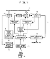
- Fig.1 is a block diagram showing the configuration of a disk apparatus according to an embodiment of the present invention
- Fig.2 is an illustrative view showing the operation of the disk apparatus according to the embodiment of the present invention
- Fig.3 is a flow chart showing the operation of the disk apparatus according to the embodiment of the present invention.
- the disk apparatus 1 is composed of: an optical pickup 3 for reading out information data recorded on an optical disk 2 by applying a laser beam to the recording surface of the optical disk 2 and detecting reflected light; a spindle motor 4 for rotating the optical disk 2; a spindle servo circuit 5 for driving the spindle motor 4 using a motor drive IC 5a to servo-control the rotational speed of the optical disk 2; a thread motor 6 for moving the optical pickup 3 threadably in the radial direction of the optical disk 2; a thread servo circuit 7 for servo-controlling the rotational direction and speed of the thread motor 6; a tracking servo circuit 8 for servo-controlling the tracking of the optical pickup 3 based on a tracking error signal detected by the optical pickup 3; a focusing servo circuit 9 for servo-controlling the focusing of the optical pickup 3 based on a focusing error signal
- the microcomputer 13 sends a control signal to the spindle servo circuit 5 to control the motor drive IC 5a and to apply a constant voltage V1 to the spindle motor 4 to set up the rotation of the optical disk 2 (refer to Fig.2 (a)).
- the microcomputer 13 detects the rotational frequency of the optical disk 2 by detecting an FG signal generated in response to the rotation of the spindle motor 4 using the rotational frequency detecting circuit 12, and detects the change in the rotational frequency of the optical disk 2 at a predetermined time interval, and then calculates the rotational acceleration of the optical disk 2 based on the change in the rotational frequency of the optical disk 2 at the predetermined time interval detected by the rotational frequency detecting circuit 12.
- the microcomputer 13 determines whether or not the weight of the optical disk 2 is greater than that of a reference optical disk based on the difference between the calculated rotational acceleration of the optical disk 2 and the rotational acceleration of the reference optical disk when the constant voltage V1 is applied to the spindle motor 4. If the weight of the optical disk 2 mounted on the disk apparatus 1 is greater than that of the reference optical disk, the rotational acceleration of the optical disk 2 is smaller than that of the reference optical disk, whereby the time required for the rotation of the optical disk 2 to reach a predetermined rotational frequency is longer than that for the rotation of the reference optical disk to reach the predetermined rotational frequency.
- the microcomputer 13 sends a control signal to the spindle servo circuit 5 to control the motor drive IC 5a and to increase the driving voltage of the spindle motor 4 up to a predetermined voltage V2 according to the weight of the optical disk 2 based on the difference between the rotational acceleration of the optical disk 2 mounted on the disk apparatus 1 and the rotational acceleration of the reference optical disk (refer to Fig.2 (a)).
- the microcomputer 13 sends a control signal to the spindle servo circuit 5 to control the motor drive IC 5a and to reduce the driving voltage of the spindle motor 4 down to a predetermined voltage V3 according to the weight of the optical disk 2, based on the difference between the rotational acceleration of the optical disk 2 mounted on the disk apparatus 1 and the rotational acceleration of the reference optical disk, so that the optical disk 2 is rotated at the predetermined rotational frequency (refer to Fig.2 (a)), and then sends a control signal to the thread servo circuit 7 to drive the thread motor 6 and to move the optical pickup 3 threadably in the radial direction of the optical disk 2 so that the optical pickup 3 reads out and reproduces information data recorded on the optical disk 2.
- This allows the rotation of the optical disk to be set up soon for shifting to a reproducing operation even if the optical disk mounted on the disk apparatus may have a large
- step S2 a constant voltage V1 is applied to the spindle motor to set up the rotation of the optical disk mounted on the disk apparatus; the change in the rotational frequency of the optical disk at a predetermined time interval when setting up the rotation of the optical disk is detected; the rotational acceleration of the optical disk is calculated based on the change in the rotational frequency of the optical disk at the predetermined time interval; and the routine proceeds to step S3.
- step S3 it is determined whether or not the weight of the optical disk mounted on the disk apparatus is greater than that of the reference optical disk based on the difference between the calculated rotational acceleration of the optical disk and the rotational acceleration of the reference optical disk, and if the weight of the optical disk mounted on the disk apparatus is greater than that of the reference optical disk, the routine proceeds to step S4, while if the weight of the optical disk mounted on the disk apparatus is not greater than that of the reference optical disk, the routine proceeds to step S5.
- step S4 the driving voltage of the spindle motor is increased up to a predetermined voltage V2 according to the weight of the optical disk mounted on the disk apparatus based on the difference between the rotational acceleration of the optical disk mounted on the disk apparatus and the rotational acceleration of the reference optical disk, and the routine proceeds to step S5.
- step S5 it is determined whether or not the rotational frequency of the optical disk reaches a predetermined rotational frequency R0, and if the rotational frequency of the optical disk reaches the predetermined rotational frequency R0, the routine proceeds to step S6, while if the rotational frequency of the optical disk does not reach the predetermined rotational frequency R0, the routine repeats step S5.
- step S6 the driving voltage of the spindle motor is reduced down to a predetermined voltage V3 according to the weight of the optical disk based on the difference between the rotational acceleration of the optical disk mounted on the disk apparatus and the rotational acceleration of the reference optical disk, so that the optical disk is rotated at the predetermined rotational frequency, and then the routine proceeds to step S7 to complete the processing.
Landscapes
- Rotational Drive Of Disk (AREA)
Abstract
Description
- The present invention relates to a disk apparatus for recording/reproducing information data onto/from an optical disk, particularly capable of setting up the rotation of the optical disk mounted on the disk apparatus soon for shifting to a reproducing operation even if the optical disk may have a large weight.
- Commercial optical disks such as DVDs (Digital Versatile Disks) and CDs (Compact Disks) generally have a diameter of 12cm or 8cm and vary in weight due to disk type and/or material (e.g. polycarbonate, PMMA (polymethylmetacrylate)), etc. even if the standards may be met. Also, some commercial optical disks are not up to the standards. Further, if a user sticks a label on an optical disk for identification of the optical disk, the weight of the optical disk is increased by the weight of the label. Fig.4 is an illustrative view showing the change in the rotational frequency of an optical disk due to the weight thereof. When a constant voltage V1 is applied to a spindle motor for rotating an optical disk to set up the rotation of the optical disk, the setup time for the rotation of an optical disk B that has a larger weight than a reference optical disk A is longer than that of the reference optical disk A as shown in Fig.4. Therefore, if an optical disk mounted on a disk apparatus has a large weight, when setting up the rotation of the optical disk to reproduce information data recorded on the optical disk, it takes the rotational frequency of the optical disk a long time to reach a predetermined rotational frequency R0, resulting in a problem in that it also takes a long time to start the reproduction from the optical disk.
- As a background art, there is known a method of: measuring the time from the setup of the rotation of a spindle motor until the rotation is stabilized; determining the weight of an optical disk based on the difference between the measured time and a reference time; and, if the optical disk is heavier or lighter than a reference disk, setting the optical disk reading speed within an allowable error range from a reference rotational frequency (refer to
Japanese Patent Laid-Open Publication No. 2004-310846 - There is also known a method of: detecting the rotational frequency of a spindle motor when setting up the rotation of an optical disk; calculating the change of the rotational frequency based on the detection result to determine the weight ratio of the optical disk; and setting a servo gain according to the weight ratio of the optical disk (refer to
Japanese Patent Laid-Open Publication No. Hei 10-293960 - There is further known a method of: measuring the gravimetrical factor of an optical disk; deciding the level and time of a reverse voltage to be applied to the spindle motor based on the measurement result; and applying the reverse voltage to the spindle motor to decelerate or stop the rotation of the optical disk (refer to
Japanese Patent Laid-Open Publication No. 2001-155417 - However, although the first one among the above-described background arts allows for: measuring the time from the setup of the rotation of a spindle motor until the rotation is stabilized; determining the weight of an optical disk based on the difference between the measured time and a reference time; and, if the optical disk is heavier or lighter than a reference disk, setting the optical disk reading speed within an allowable error range from a reference rotational frequency, the method is intended only to set the optical disk reading speed suitably for the mounted optical disk by confirming whether or not the optical disk is heavier or lighter than the reference disk before starting a reproducing operation for the optical disk, but to solve the above-described problem.
- Although the next one allows for: detecting the rotational frequency of a spindle motor when setting up the rotation of an optical disk; calculating the change of the rotational frequency based on the detection result to determine the weight ratio of the optical disk; and setting a servo gain according to the weight ratio of the optical disk, the method is intended only to drive the spindle motor at a minimum current consumption according to the weight of the optical disk, but to solve the above-described problem.
- Although the further next one allows for: measuring the gravimetrical factor of an optical disk; deciding the level and time of a reverse voltage to be applied to the spindle motor based on the measurement result; and applying the reverse voltage to the spindle motor to decelerate or stop the rotation of the optical disk, the method is intended only to absorb the variation of optical disk weight, variation of the power supply voltage for driving the spindle motor, and variation of the spindle motor to stop the rotation of the optical disk, but to solve the above-described problem.
- The present invention has been made in consideration of the above-described problems included in the background arts, and an object thereof is to provide a disk apparatus adapted to allow the rotational frequency of an optical disk to reach a predetermined rotational frequency soon for shifting to a reproducing operation, when setting up the rotation of the optical disk, even if the optical disk may have a large weight.
- In order to achieve the foregoing object, the present invention is directed to a disk apparatus for recording/reproducing information data onto/from an optical disk, including: rotational frequency detecting means for detecting the change in the rotational frequency of the optical disk at a predetermined time interval; calculating means for calculating the rotational acceleration of the optical disk based on the change in the rotational frequency of the optical disk at the predetermined time interval detected by the rotational frequency detecting means; determining means for determining whether or not the weight of the optical disk is greater than that of a reference optical disk based on the difference between the rotational acceleration of the optical disk calculated by the calculating means and the rotational acceleration of the reference optical disk; and first control means adapted to increase the driving voltage of a spindle motor, if it is determined by the determining means that the weight of the optical disk is greater than that of the reference optical disk.
- The first control means is preferably adapted to increase the driving voltage of the spindle motor up to a first predetermined voltage according to the weight of the optical disk based on the difference between the rotational acceleration of the optical disk calculated by the calculating means and the rotational acceleration of the reference optical disk, if it is determined by the determining means that the weight of the optical disk is greater than that of the reference optical disk.
- There is further provided second control means adapted to reduce the driving voltage of the spindle motor and to rotate the optical disk at a predetermined rotational frequency, when the rotational frequency of the optical disk reaches the predetermined rotational frequency.
- The second control means is preferably adapted to reduce the driving voltage of the spindle motor down to a second predetermined voltage according to the weight of the optical disk based on the difference between the rotational acceleration of the optical disk calculated by the calculating means and the rotational acceleration of the reference optical disk and to rotate the optical disk at the predetermined rotational frequency.
- In accordance with these means, it is possible to allow the rotational frequency of the optical disk to reach a predetermined rotational frequency soon for shifting to a reproducing operation, when setting up the rotation of the optical disk, even if the optical disk may have a large weight.
- In accordance with the disk apparatus according to the first aspect of the present invention, the change in the rotational frequency of the optical disk is detected at the predetermined time interval; the rotational acceleration of the optical disk is calculated based on the detected change in the rotational frequency of the optical disk at the predetermined time interval; it is determined whether or not the weight of the optical disk is greater than that of the reference optical disk based on the difference between the calculated rotational acceleration of the optical disk and the rotational acceleration of the reference optical disk; the driving voltage of the spindle motor is increased up to a first predetermined voltage according to the weight of the optical disk based on the difference between the calculated rotational acceleration of the optical disk and the rotational acceleration of the reference optical disk if it is determined that the weight of the optical disk is greater than that of the reference optical disk; and the driving voltage of the spindle motor is reduced down to a second predetermined voltage according to the weight of the optical disk based on the difference between the calculated rotational acceleration of the optical disk and the rotational acceleration of the reference optical disk, when the rotational frequency of the optical disk reaches a predetermined rotational frequency, so that the optical disk is rotated at the predetermined rotational frequency. Therefore, if the weight of the optical disk is greater than that of the reference optical disk, it is possible to allow the rotational frequency of the optical disk to reach a predetermined rotational frequency soon for shifting to a reproducing operation, when setting up the optical disk, by increasing the driving voltage of the spindle motor and thereby the rotational acceleration of the optical disk, and after the rotational frequency of the optical disk reaches the predetermined rotational frequency, it is possible to rotate the optical disk at the predetermined rotational frequency by reducing the driving voltage of the spindle motor so that the rotational frequency of the optical disk keeps the predetermined rotational frequency.
- In accordance with the disk apparatus according to the second aspect of the present invention, the change in the rotational frequency of the optical disk is detected at the predetermined time interval; the rotational acceleration of the optical disk is calculated based on the detected change in the rotational frequency of the optical disk at the predetermined time interval; it is determined whether or not the weight of the optical disk is greater than that of the reference optical disk based on the difference between the calculated rotational acceleration of the optical disk and the rotational acceleration of the reference optical disk; and the driving voltage of the spindle motor is increased if it is determined that the weight of the optical disk is greater than that of the reference optical disk. Therefore, if the weight of the optical disk is greater than that of the reference optical disk, it is possible to allow the rotational frequency of the optical disk to reach a predetermined rotational frequency soon, when setting up the optical disk, by increasing the driving voltage of the spindle motor and thereby the rotational acceleration of the optical disk.
- In accordance with the disk apparatus according to the third aspect of the present invention, if it is determined that the weight of the optical disk is greater than that of the reference optical disk, the driving voltage of the spindle motor is increased up to a first predetermined voltage according to the weight of the optical disk based on the difference between the calculated rotational acceleration of the optical disk and the rotational acceleration of the reference optical disk. Therefore, if the weight of the optical disk is greater than that of the reference optical disk, it is possible to allow the rotational frequency of the optical disk to reach a predetermined rotational frequency soon, when setting up the optical disk, by increasing the driving voltage of the spindle motor up to a voltage according to the weight of the optical disk and thereby increasing the rotational acceleration of the optical disk.
- In accordance with the disk apparatus according to the fourth aspect of the present invention, when the rotational frequency of the optical disk reaches the predetermined rotational frequency, the driving voltage of the spindle motor is reduced to rotate the optical disk at the predetermined rotational frequency. Therefore, after the rotational frequency of the optical disk reaches the predetermined rotational frequency, it is possible to rotate the optical disk at the predetermined rotational frequency by reducing the driving voltage of the spindle motor so that the rotational frequency of the optical disk keeps the predetermined rotational frequency.
- In accordance with the disk apparatus according to the fifth aspect of the present invention, the driving voltage of the spindle motor is reduced down to a second predetermined voltage according to the weight of the optical disk based on the difference between the calculated rotational acceleration of the optical disk and the rotational acceleration of the reference optical disk so that the optical disk is rotated at the predetermined rotational frequency. Therefore, after the rotational frequency of the optical disk reaches the predetermined rotational frequency, it is possible to rotate the optical disk at the predetermined rotational frequency by reducing the driving voltage of the spindle motor down to a voltage according to the weight of the optical disk so that the rotational frequency of the optical disk keeps the predetermined rotational frequency.
-
- Fig.1 is a block diagram showing the configuration of a disk apparatus according to an embodiment of the present invention;
- Fig.2 is an illustrative view showing the operation of the disk apparatus according to the embodiment of the present invention;
- Fig.3 is a flow chart showing the operation of the disk apparatus according to the embodiment of the present invention; and
- Fig.4 is an illustrative view showing the change in the rotational frequency of an optical disk due to the weight thereof.
- The best mode for carrying out the present invention will hereinafter be described in detail with appropriate reference to the accompanying drawings. Fig.1 is a block diagram showing the configuration of a disk apparatus according to an embodiment of the present invention; Fig.2 is an illustrative view showing the operation of the disk apparatus according to the embodiment of the present invention; and Fig.3 is a flow chart showing the operation of the disk apparatus according to the embodiment of the present invention.
- First it will be described the configuration of the disk apparatus according to the embodiment of the present invention based on the block diagram shown in Fig.1. The
disk apparatus 1 is composed of: anoptical pickup 3 for reading out information data recorded on anoptical disk 2 by applying a laser beam to the recording surface of theoptical disk 2 and detecting reflected light; aspindle motor 4 for rotating theoptical disk 2; aspindle servo circuit 5 for driving thespindle motor 4 using amotor drive IC 5a to servo-control the rotational speed of theoptical disk 2; athread motor 6 for moving theoptical pickup 3 threadably in the radial direction of theoptical disk 2; athread servo circuit 7 for servo-controlling the rotational direction and speed of thethread motor 6; atracking servo circuit 8 for servo-controlling the tracking of theoptical pickup 3 based on a tracking error signal detected by theoptical pickup 3; a focusing servo circuit 9 for servo-controlling the focusing of theoptical pickup 3 based on a focusing error signal detected by theoptical pickup 3; anRF amplifier circuit 10 for amplifying an information data RF (Radio Frequency) signal read out by theoptical pickup 3; asignal processing circuit 11 for reproducing the information data recorded on theoptical disk 2 by synchronously detecting and demodulating the information data RF signal amplified by theRF amplifier circuit 10 based on a reference clock, correcting errors in the demodulated information data, and expanding and decoding the information data compressed based on a predetermined compression method; a rotationalfrequency detecting circuit 12 for detecting the rotational frequency of theoptical disk 2 by detecting an FG (Frequency Generator) signal generated in response to the rotation of thespindle motor 4; amicrocomputer 13 for controlling the entire system of thedisk apparatus 1; and a remotecontrol receiving unit 14 for receiving an infrared remote control signal transmitted from aremote control unit 20 and converting the signal into a predetermined electrical signal. The operation of the thus arranged disk apparatus will hereinafter be described. - When the reproduction from the
optical disk 2 mounted on thedisk apparatus 1 is instructed through a key operation using theremote control unit 20, themicrocomputer 13 sends a control signal to thespindle servo circuit 5 to control themotor drive IC 5a and to apply a constant voltage V1 to thespindle motor 4 to set up the rotation of the optical disk 2 (refer to Fig.2 (a)). When the rotation of theoptical disk 2 is set up, themicrocomputer 13 detects the rotational frequency of theoptical disk 2 by detecting an FG signal generated in response to the rotation of thespindle motor 4 using the rotationalfrequency detecting circuit 12, and detects the change in the rotational frequency of theoptical disk 2 at a predetermined time interval, and then calculates the rotational acceleration of theoptical disk 2 based on the change in the rotational frequency of theoptical disk 2 at the predetermined time interval detected by the rotationalfrequency detecting circuit 12. Then, themicrocomputer 13 determines whether or not the weight of theoptical disk 2 is greater than that of a reference optical disk based on the difference between the calculated rotational acceleration of theoptical disk 2 and the rotational acceleration of the reference optical disk when the constant voltage V1 is applied to thespindle motor 4. If the weight of theoptical disk 2 mounted on thedisk apparatus 1 is greater than that of the reference optical disk, the rotational acceleration of theoptical disk 2 is smaller than that of the reference optical disk, whereby the time required for the rotation of theoptical disk 2 to reach a predetermined rotational frequency is longer than that for the rotation of the reference optical disk to reach the predetermined rotational frequency. - If the weight of the
optical disk 2 is greater than that of the reference optical disk, in order to shorten the time required for the rotational frequency of theoptical disk 2 mounted on thedisk apparatus 1 to reach a predetermined rotational frequency R0 within a predetermined time period, themicrocomputer 13 sends a control signal to thespindle servo circuit 5 to control themotor drive IC 5a and to increase the driving voltage of thespindle motor 4 up to a predetermined voltage V2 according to the weight of theoptical disk 2 based on the difference between the rotational acceleration of theoptical disk 2 mounted on thedisk apparatus 1 and the rotational acceleration of the reference optical disk (refer to Fig.2 (a)). When the driving voltage of thespindle motor 4 for rotating theoptical disk 2 is increased up to the predetermined voltage V2, the rotational acceleration of theoptical disk 2 mounted on thedisk apparatus 1 is also increased, whereby the time required for the rotational frequency of theoptical disk 2 to reach the predetermined rotational frequency can be shortened (refer to Fig.2 (b)). - When the rotational frequency of the
optical disk 2 mounted on thedisk apparatus 1 reaches the predetermined rotational frequency (refer to Fig.2 (b)), themicrocomputer 13 sends a control signal to thespindle servo circuit 5 to control themotor drive IC 5a and to reduce the driving voltage of thespindle motor 4 down to a predetermined voltage V3 according to the weight of theoptical disk 2, based on the difference between the rotational acceleration of theoptical disk 2 mounted on thedisk apparatus 1 and the rotational acceleration of the reference optical disk, so that theoptical disk 2 is rotated at the predetermined rotational frequency (refer to Fig.2 (a)), and then sends a control signal to thethread servo circuit 7 to drive thethread motor 6 and to move theoptical pickup 3 threadably in the radial direction of theoptical disk 2 so that theoptical pickup 3 reads out and reproduces information data recorded on theoptical disk 2. This allows the rotation of the optical disk to be set up soon for shifting to a reproducing operation even if the optical disk mounted on the disk apparatus may have a large weight. - The operation of the disk apparatus according to the embodiment of the present invention will also be described based on the flow chart shown in Fig.3.
- When the reproduction from the optical disk is instructed through a key operation using the remote control unit, the routine proceeds from step S1 to step S2. In step S2, a constant voltage V1 is applied to the spindle motor to set up the rotation of the optical disk mounted on the disk apparatus; the change in the rotational frequency of the optical disk at a predetermined time interval when setting up the rotation of the optical disk is detected; the rotational acceleration of the optical disk is calculated based on the change in the rotational frequency of the optical disk at the predetermined time interval; and the routine proceeds to step S3.
- In step S3, it is determined whether or not the weight of the optical disk mounted on the disk apparatus is greater than that of the reference optical disk based on the difference between the calculated rotational acceleration of the optical disk and the rotational acceleration of the reference optical disk, and if the weight of the optical disk mounted on the disk apparatus is greater than that of the reference optical disk, the routine proceeds to step S4, while if the weight of the optical disk mounted on the disk apparatus is not greater than that of the reference optical disk, the routine proceeds to step S5.
- In step S4, the driving voltage of the spindle motor is increased up to a predetermined voltage V2 according to the weight of the optical disk mounted on the disk apparatus based on the difference between the rotational acceleration of the optical disk mounted on the disk apparatus and the rotational acceleration of the reference optical disk, and the routine proceeds to step S5.
- In step S5, it is determined whether or not the rotational frequency of the optical disk reaches a predetermined rotational frequency R0, and if the rotational frequency of the optical disk reaches the predetermined rotational frequency R0, the routine proceeds to step S6, while if the rotational frequency of the optical disk does not reach the predetermined rotational frequency R0, the routine repeats step S5.
- In step S6, the driving voltage of the spindle motor is reduced down to a predetermined voltage V3 according to the weight of the optical disk based on the difference between the rotational acceleration of the optical disk mounted on the disk apparatus and the rotational acceleration of the reference optical disk, so that the optical disk is rotated at the predetermined rotational frequency, and then the routine proceeds to step S7 to complete the processing.
- Although the best mode for carrying out the present invention has heretofore been described in detail, the present invention is not restricted thereto, and it will be appreciated that modifications and improvements may be made within the ordinary knowledge of those skilled in the art.
Claims (5)
- A disk apparatus for recording/reproducing information data onto/from an optical disk, comprising:rotational frequency detecting means for detecting the change in the rotational frequency of said optical disk at a predetermined time interval;calculating means for calculating the rotational acceleration of said optical disk based on the change in the rotational frequency of said optical disk at said predetermined time interval detected by said rotational frequency detecting means;determining means for determining whether or not the weight of said optical disk is greater than that of a reference optical disk based on the difference between the rotational acceleration of said optical disk calculated by said calculating means and the rotational acceleration of said reference optical disk;first control means adapted to increase the driving voltage of a spindle motor up to a first predetermined voltage according to the weight of said optical disk based on the difference between the rotational acceleration of said optical disk calculated by said calculating means and the rotational acceleration of said reference optical disk, if it is determined by said determining means that the weight of said optical disk is greater than that of said reference optical disk; andsecond control means adapted to reduce the driving voltage of said spindle motor down to a second predetermined voltage according to the weight of said optical disk based on the difference between the rotational acceleration of said optical disk calculated by said calculating means and the rotational acceleration of said reference optical disk and to rotate said optical disk at a predetermined rotational frequency, when the rotational frequency of said optical disk reaches said predetermined rotational frequency.
- A disk apparatus for recording/reproducing information data onto/from an optical disk, comprising:rotational frequency detecting means for detecting the change in the rotational frequency of said optical disk at a predetermined time interval;calculating means for calculating the rotational acceleration of said optical disk based on the change in the rotational frequency of said optical disk at said predetermined time interval detected by said rotational frequency detecting means;determining means for determining whether or not the weight of said optical disk is greater than that of a reference optical disk based on the difference between the rotational acceleration of said optical disk calculated by said calculating means and the rotational acceleration of said reference optical disk; andfirst control means adapted to increase the driving voltage of a spindle motor, if it is determined by said determining means that the weight of said optical disk is greater than that of said reference optical disk.
- The disk apparatus according to claim 2, wherein said first control means is adapted to increase the driving voltage of said spindle motor up to a first predetermined voltage according to the weight of said optical disk based on the difference between the rotational acceleration of said optical disk calculated by said calculating means and the rotational acceleration of said reference optical disk, if it is determined by said determining means that the weight of said optical disk is greater than that of said reference optical disk.
- The disk apparatus according to claim 2, further comprising second control means adapted to reduce the driving voltage of said spindle motor and to rotate said optical disk at a predetermined rotational frequency, when the rotational frequency of said optical disk reaches said predetermined rotational frequency.
- The disk apparatus according to claim 4, wherein said second control means is adapted to reduce the driving voltage of said spindle motor down to a second predetermined voltage according to the weight of said optical disk based on the difference between the rotational acceleration of said optical disk calculated by said calculating means and the rotational acceleration of said reference optical disk and to rotate said optical disk at said predetermined rotational frequency.
Applications Claiming Priority (1)
| Application Number | Priority Date | Filing Date | Title |
|---|---|---|---|
| JP2005293080A JP2007102951A (en) | 2005-10-05 | 2005-10-05 | Disk apparatus |
Publications (3)
| Publication Number | Publication Date |
|---|---|
| EP1772864A2 true EP1772864A2 (en) | 2007-04-11 |
| EP1772864A3 EP1772864A3 (en) | 2008-12-24 |
| EP1772864B1 EP1772864B1 (en) | 2010-02-10 |
Family
ID=37569645
Family Applications (1)
| Application Number | Title | Priority Date | Filing Date |
|---|---|---|---|
| EP06020630A Not-in-force EP1772864B1 (en) | 2005-10-05 | 2006-09-29 | Disk apparatus |
Country Status (4)
| Country | Link |
|---|---|
| US (1) | US7561505B2 (en) |
| EP (1) | EP1772864B1 (en) |
| JP (1) | JP2007102951A (en) |
| DE (1) | DE602006012147D1 (en) |
Families Citing this family (2)
| Publication number | Priority date | Publication date | Assignee | Title |
|---|---|---|---|---|
| JP2007207374A (en) * | 2006-02-03 | 2007-08-16 | Fujitsu Ltd | Storage device, spindle motor control method, and program |
| US11644986B1 (en) * | 2021-11-20 | 2023-05-09 | Western Digital Technologies, Inc. | Adaptive power loss management for data storage devices |
Citations (4)
| Publication number | Priority date | Publication date | Assignee | Title |
|---|---|---|---|---|
| US4653040A (en) | 1984-03-16 | 1987-03-24 | Pioneer Electronic Corporation | Disk size detecting circuit |
| US5042025A (en) | 1988-12-27 | 1991-08-20 | Pioneer Electronic Corporation | Rotation control system for disk player |
| US5748591A (en) | 1995-10-30 | 1998-05-05 | Sony Corporation | Disk drive |
| US20010043533A1 (en) | 2000-03-03 | 2001-11-22 | Hahnfeld Jerry L. | Optical reader/player preventing the unauthorized reading of information-carrying substrates |
Family Cites Families (7)
| Publication number | Priority date | Publication date | Assignee | Title |
|---|---|---|---|---|
| EP0768660B1 (en) * | 1995-03-08 | 2004-01-07 | Matsushita Electric Industrial Co., Ltd. | Device and method for reproducing data from disk, method for controlling rotation of disk, and reproduction clock generating device |
| US6195321B1 (en) * | 1995-10-26 | 2001-02-27 | Matsushita Electric Industrial Company, Ltd. | Disk rotation control apparatus with deceleration means |
| JPH10293960A (en) | 1997-02-21 | 1998-11-04 | Matsushita Electric Ind Co Ltd | Disk driving method and disk device |
| JPH11317006A (en) * | 1998-05-07 | 1999-11-16 | Samsung Electronics Co Ltd | Imbalanced disk reading method |
| JP4553429B2 (en) | 1999-11-25 | 2010-09-29 | パナソニック株式会社 | Disk unit |
| KR20040004831A (en) * | 2002-07-05 | 2004-01-16 | 삼성전자주식회사 | Method for controlling a step motor of optical disc driving system and apparatus therefor |
| JP2004310846A (en) | 2003-04-04 | 2004-11-04 | Funai Electric Co Ltd | Disk device |
-
2005
- 2005-10-05 JP JP2005293080A patent/JP2007102951A/en active Pending
-
2006
- 2006-09-29 EP EP06020630A patent/EP1772864B1/en not_active Not-in-force
- 2006-09-29 DE DE602006012147T patent/DE602006012147D1/en active Active
- 2006-10-03 US US11/541,697 patent/US7561505B2/en not_active Expired - Fee Related
Patent Citations (4)
| Publication number | Priority date | Publication date | Assignee | Title |
|---|---|---|---|---|
| US4653040A (en) | 1984-03-16 | 1987-03-24 | Pioneer Electronic Corporation | Disk size detecting circuit |
| US5042025A (en) | 1988-12-27 | 1991-08-20 | Pioneer Electronic Corporation | Rotation control system for disk player |
| US5748591A (en) | 1995-10-30 | 1998-05-05 | Sony Corporation | Disk drive |
| US20010043533A1 (en) | 2000-03-03 | 2001-11-22 | Hahnfeld Jerry L. | Optical reader/player preventing the unauthorized reading of information-carrying substrates |
Also Published As
| Publication number | Publication date |
|---|---|
| US20070076549A1 (en) | 2007-04-05 |
| EP1772864A3 (en) | 2008-12-24 |
| DE602006012147D1 (en) | 2010-03-25 |
| US7561505B2 (en) | 2009-07-14 |
| JP2007102951A (en) | 2007-04-19 |
| EP1772864B1 (en) | 2010-02-10 |
Similar Documents
| Publication | Publication Date | Title |
|---|---|---|
| EP1191529A2 (en) | Optical disk drive, and method for identifying optical disks mounted thereto | |
| JP2002117534A (en) | Optical disk reproducing device and kind of disk discriminating method | |
| US7561505B2 (en) | Disk apparatus | |
| US6414924B1 (en) | Method and apparatus capable of identifying different types of disk-shaped information storage media | |
| JPS61160838A (en) | Optical information recording and reproducing device | |
| KR19980033267A (en) | Disk playback apparatus and method thereof | |
| JP3885807B2 (en) | Optical disk device | |
| US20060104170A1 (en) | Method for performing servo control for blank discs | |
| US20060171266A1 (en) | Tilt adjustment apparatus and method | |
| US20070041292A1 (en) | Disk reproducing apparatus | |
| US7317667B2 (en) | Wobble signal extraction circuit and optical disk device | |
| JPH0632161B2 (en) | Disc player | |
| JP3608738B2 (en) | Transducer adjustment device and transducer adjustment method | |
| US20060158978A1 (en) | Optical disk apparatus | |
| KR20010051802A (en) | Disk reproducing method and disk reproducing apparatus | |
| JP2002222562A (en) | Method for controlling recording of optical disk recording and reproducing device | |
| KR100521921B1 (en) | Method and apparatus for measuring axial vibration of a disk | |
| JP2007018644A (en) | Disk apparatus and tilt adjusting method thereof | |
| JP2004127377A (en) | Optical disk recording/reproducing device, optical disk device, and method for measuring eccentric amount of the optical disk device | |
| JP2000251258A (en) | Optical disk recording/reproducing device | |
| JP2005353246A (en) | Pickup device and optical disk device provided with the same | |
| JP2007087560A (en) | Disk reproducing apparatus | |
| JPH09128878A (en) | Disk detection method of disk player | |
| JP2000251261A (en) | Optical disc recording/playback apparatus | |
| JPH11328709A (en) | Laser output setting method for optical disk recording/ reproducing device |
Legal Events
| Date | Code | Title | Description |
|---|---|---|---|
| PUAI | Public reference made under article 153(3) epc to a published international application that has entered the european phase |
Free format text: ORIGINAL CODE: 0009012 |
|
| AK | Designated contracting states |
Kind code of ref document: A2 Designated state(s): AT BE BG CH CY CZ DE DK EE ES FI FR GB GR HU IE IS IT LI LT LU LV MC NL PL PT RO SE SI SK TR |
|
| AX | Request for extension of the european patent |
Extension state: AL BA HR MK YU |
|
| PUAL | Search report despatched |
Free format text: ORIGINAL CODE: 0009013 |
|
| AK | Designated contracting states |
Kind code of ref document: A3 Designated state(s): AT BE BG CH CY CZ DE DK EE ES FI FR GB GR HU IE IS IT LI LT LU LV MC NL PL PT RO SE SI SK TR |
|
| AX | Request for extension of the european patent |
Extension state: AL BA HR MK RS |
|
| 17P | Request for examination filed |
Effective date: 20090422 |
|
| GRAP | Despatch of communication of intention to grant a patent |
Free format text: ORIGINAL CODE: EPIDOSNIGR1 |
|
| AKX | Designation fees paid |
Designated state(s): DE FR GB |
|
| GRAS | Grant fee paid |
Free format text: ORIGINAL CODE: EPIDOSNIGR3 |
|
| GRAA | (expected) grant |
Free format text: ORIGINAL CODE: 0009210 |
|
| AK | Designated contracting states |
Kind code of ref document: B1 Designated state(s): DE FR GB |
|
| REG | Reference to a national code |
Ref country code: GB Ref legal event code: FG4D |
|
| REF | Corresponds to: |
Ref document number: 602006012147 Country of ref document: DE Date of ref document: 20100325 Kind code of ref document: P |
|
| PLBE | No opposition filed within time limit |
Free format text: ORIGINAL CODE: 0009261 |
|
| STAA | Information on the status of an ep patent application or granted ep patent |
Free format text: STATUS: NO OPPOSITION FILED WITHIN TIME LIMIT |
|
| 26N | No opposition filed |
Effective date: 20101111 |
|
| REG | Reference to a national code |
Ref country code: FR Ref legal event code: PLFP Year of fee payment: 10 |
|
| PGFP | Annual fee paid to national office [announced via postgrant information from national office to epo] |
Ref country code: DE Payment date: 20150922 Year of fee payment: 10 Ref country code: GB Payment date: 20150923 Year of fee payment: 10 |
|
| PGFP | Annual fee paid to national office [announced via postgrant information from national office to epo] |
Ref country code: FR Payment date: 20150811 Year of fee payment: 10 |
|
| REG | Reference to a national code |
Ref country code: DE Ref legal event code: R119 Ref document number: 602006012147 Country of ref document: DE |
|
| GBPC | Gb: european patent ceased through non-payment of renewal fee |
Effective date: 20160929 |
|
| REG | Reference to a national code |
Ref country code: FR Ref legal event code: ST Effective date: 20170531 |
|
| PG25 | Lapsed in a contracting state [announced via postgrant information from national office to epo] |
Ref country code: DE Free format text: LAPSE BECAUSE OF NON-PAYMENT OF DUE FEES Effective date: 20170401 Ref country code: FR Free format text: LAPSE BECAUSE OF NON-PAYMENT OF DUE FEES Effective date: 20160930 Ref country code: GB Free format text: LAPSE BECAUSE OF NON-PAYMENT OF DUE FEES Effective date: 20160929 |