EP1772601A1 - Exhaust system of motorcycle and motorcycle including exhaust system - Google Patents
Exhaust system of motorcycle and motorcycle including exhaust system Download PDFInfo
- Publication number
- EP1772601A1 EP1772601A1 EP06254600A EP06254600A EP1772601A1 EP 1772601 A1 EP1772601 A1 EP 1772601A1 EP 06254600 A EP06254600 A EP 06254600A EP 06254600 A EP06254600 A EP 06254600A EP 1772601 A1 EP1772601 A1 EP 1772601A1
- Authority
- EP
- European Patent Office
- Prior art keywords
- exhaust
- motorcycle
- chamber
- pipes
- exhaust system
- Prior art date
- Legal status (The legal status is an assumption and is not a legal conclusion. Google has not performed a legal analysis and makes no representation as to the accuracy of the status listed.)
- Granted
Links
Images

Classifications
-
- F—MECHANICAL ENGINEERING; LIGHTING; HEATING; WEAPONS; BLASTING
- F01—MACHINES OR ENGINES IN GENERAL; ENGINE PLANTS IN GENERAL; STEAM ENGINES
- F01N—GAS-FLOW SILENCERS OR EXHAUST APPARATUS FOR MACHINES OR ENGINES IN GENERAL; GAS-FLOW SILENCERS OR EXHAUST APPARATUS FOR INTERNAL-COMBUSTION ENGINES
- F01N3/00—Exhaust or silencing apparatus having means for purifying, rendering innocuous, or otherwise treating exhaust
- F01N3/08—Exhaust or silencing apparatus having means for purifying, rendering innocuous, or otherwise treating exhaust for rendering innocuous
- F01N3/10—Exhaust or silencing apparatus having means for purifying, rendering innocuous, or otherwise treating exhaust for rendering innocuous by thermal or catalytic conversion of noxious components of exhaust
-
- F—MECHANICAL ENGINEERING; LIGHTING; HEATING; WEAPONS; BLASTING
- F01—MACHINES OR ENGINES IN GENERAL; ENGINE PLANTS IN GENERAL; STEAM ENGINES
- F01N—GAS-FLOW SILENCERS OR EXHAUST APPARATUS FOR MACHINES OR ENGINES IN GENERAL; GAS-FLOW SILENCERS OR EXHAUST APPARATUS FOR INTERNAL-COMBUSTION ENGINES
- F01N13/00—Exhaust or silencing apparatus characterised by constructional features
- F01N13/011—Exhaust or silencing apparatus characterised by constructional features having two or more purifying devices arranged in parallel
-
- F—MECHANICAL ENGINEERING; LIGHTING; HEATING; WEAPONS; BLASTING
- F01—MACHINES OR ENGINES IN GENERAL; ENGINE PLANTS IN GENERAL; STEAM ENGINES
- F01N—GAS-FLOW SILENCERS OR EXHAUST APPARATUS FOR MACHINES OR ENGINES IN GENERAL; GAS-FLOW SILENCERS OR EXHAUST APPARATUS FOR INTERNAL-COMBUSTION ENGINES
- F01N13/00—Exhaust or silencing apparatus characterised by constructional features
- F01N13/08—Other arrangements or adaptations of exhaust conduits
-
- F—MECHANICAL ENGINEERING; LIGHTING; HEATING; WEAPONS; BLASTING
- F01—MACHINES OR ENGINES IN GENERAL; ENGINE PLANTS IN GENERAL; STEAM ENGINES
- F01N—GAS-FLOW SILENCERS OR EXHAUST APPARATUS FOR MACHINES OR ENGINES IN GENERAL; GAS-FLOW SILENCERS OR EXHAUST APPARATUS FOR INTERNAL-COMBUSTION ENGINES
- F01N2340/00—Dimensional characteristics of the exhaust system, e.g. length, diameter or volume of the exhaust apparatus; Spatial arrangements of exhaust apparatuses
- F01N2340/04—Arrangement of the exhaust system relative to a vehicle or parts thereof
-
- F—MECHANICAL ENGINEERING; LIGHTING; HEATING; WEAPONS; BLASTING
- F01—MACHINES OR ENGINES IN GENERAL; ENGINE PLANTS IN GENERAL; STEAM ENGINES
- F01N—GAS-FLOW SILENCERS OR EXHAUST APPARATUS FOR MACHINES OR ENGINES IN GENERAL; GAS-FLOW SILENCERS OR EXHAUST APPARATUS FOR INTERNAL-COMBUSTION ENGINES
- F01N2470/00—Structure or shape of exhaust gas passages, pipes or tubes
- F01N2470/14—Plurality of outlet tubes, e.g. in parallel or with different length
-
- F—MECHANICAL ENGINEERING; LIGHTING; HEATING; WEAPONS; BLASTING
- F01—MACHINES OR ENGINES IN GENERAL; ENGINE PLANTS IN GENERAL; STEAM ENGINES
- F01N—GAS-FLOW SILENCERS OR EXHAUST APPARATUS FOR MACHINES OR ENGINES IN GENERAL; GAS-FLOW SILENCERS OR EXHAUST APPARATUS FOR INTERNAL-COMBUSTION ENGINES
- F01N2470/00—Structure or shape of exhaust gas passages, pipes or tubes
- F01N2470/16—Plurality of inlet tubes, e.g. discharging into different chambers
-
- F—MECHANICAL ENGINEERING; LIGHTING; HEATING; WEAPONS; BLASTING
- F01—MACHINES OR ENGINES IN GENERAL; ENGINE PLANTS IN GENERAL; STEAM ENGINES
- F01N—GAS-FLOW SILENCERS OR EXHAUST APPARATUS FOR MACHINES OR ENGINES IN GENERAL; GAS-FLOW SILENCERS OR EXHAUST APPARATUS FOR INTERNAL-COMBUSTION ENGINES
- F01N2590/00—Exhaust or silencing apparatus adapted to particular use, e.g. for military applications, airplanes, submarines
- F01N2590/04—Exhaust or silencing apparatus adapted to particular use, e.g. for military applications, airplanes, submarines for motorcycles
-
- Y—GENERAL TAGGING OF NEW TECHNOLOGICAL DEVELOPMENTS; GENERAL TAGGING OF CROSS-SECTIONAL TECHNOLOGIES SPANNING OVER SEVERAL SECTIONS OF THE IPC; TECHNICAL SUBJECTS COVERED BY FORMER USPC CROSS-REFERENCE ART COLLECTIONS [XRACs] AND DIGESTS
- Y02—TECHNOLOGIES OR APPLICATIONS FOR MITIGATION OR ADAPTATION AGAINST CLIMATE CHANGE
- Y02A—TECHNOLOGIES FOR ADAPTATION TO CLIMATE CHANGE
- Y02A50/00—TECHNOLOGIES FOR ADAPTATION TO CLIMATE CHANGE in human health protection, e.g. against extreme weather
- Y02A50/20—Air quality improvement or preservation, e.g. vehicle emission control or emission reduction by using catalytic converters
Definitions
- the present invention relates to an exhaust system of a motorcycle, and more particularly to an exhaust system of a motorcycle which has a V-type engine and an exhaust gas purifying function.
- the invention also relates to a motorcycle including this exhaust system.
- an exhaust system of a motorcycle which includes a V-type engine, front exhaust pipes connected with cylinders disposed before an engine and rear exhaust pipes connected with cylinders disposed behind the engine are joined to an exhaust muffler via an exhaust chamber.
- both the front exhaust pipes and the rear exhaust pipes collectively joined to the exhaust chamber preferably have their optimum length so as to secure appropriate function of the engine. While the front exhaust pipes sufficiently have the optimum length, the rear exhaust pipes have only a short length to reach the exhaust chamber and therefore cannot easily obtain the same length as that of the front exhaust pipes.
- Patent reference JP-A-62-60914 disclose a layout of an exhaust system where the length of the rear exhaust pipes is made substantially equivalent to that of the front exhaust pipes by connecting the rear exhaust pipes to the exhaust chamber in a zigzag line, for example.
- Patent reference JP-A-59-99020 proposes a technique of containing catalyst in the exhaust muffler.
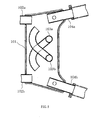
- Fig. 5 is a vertical cross-sectional plan view of an exhaust chamber 101 shown in JP-A-59-99020 .
- Front exhaust pipes 102a and 102b are connected with the front part of an exhaust chamber 101
- rear exhaust pipes 103a and 103b are connected with the upper part of the exhaust chamber 101.
- the rear exhaust pipes 103a and 103b cross each other within the exhaust chamber 101 and extend from the cross point.
- the opening ends of the front exhaust pipes 102a and 102b and the rear exhaust pipes 103a and 103b are directed toward the opening ends of joint pipes 104a and 104b, which are joined to an exhaust muffler (not shown).
- the rear exhaust pipes 103a and 103b have sufficient length, and high-temperature exhaust gas discharged from the front exhaust pipes 102a and 102b and the rear exhaust pipes 103a and 103b are injected to the joint pipes 104a and 104b such that the exhaust gas can be introduced to the catalyst contained in the exhaust muffler without lowering the temperature of the exhaust gas.
- the performance of the engine can be secured and purification of the exhaust gas can be promoted.
- exhaust gas is purified by the catalyst contained in the exhaust muffler.
- the catalyst used in this method is constituted by ceramics coated with noble metals such as platinum or metal filters, and thus the weight of the catalyst becomes 1 kilogram or larger in some cases.
- the heavy component of the motorcycle is located at a rear position away from the center of gravity of the vehicle body, which deteriorates steering stability of the vehicle.
- An exhaust system of a motorcycle includes front exhaust pipes adapted to be connected with front cylinders of a V-type engine, rear exhaust pipes adapted to be connected with rear cylinders of the engine, and an exhaust chamber connected with the respective rear ends of the front exhaust pipes and the rear exhaust pipes.
- the rear ends of the front exhaust pipes are connected with the front part of the exhaust chamber.
- the rear ends of the rear exhaust pipes are connected with the upper part of the exhaust chamber. Exhaust gases discharged from the front exhaust pipes and the rear exhaust pipes are unified within the exhaust chamber, and a catalyst is disposed in the vicinity of the unifying section.
- the length of the rear exhaust pipes is shorter than the length of the front exhaust pipes.
- an exhaust muffler is connected with the rear part of the exhaust chamber.
- one or more catalysts may be disposed within at least one of the front exhaust pipes.
- the motorcycle includes a vehicle body frame, a transmission chamber provided behind the V-type engine, a swing arm disposed behind the transmission chamber and supported by the vehicle body frame, and an oil pan equipped below the V-type engine.
- the exhaust chamber is disposed behind the oil pan and below a space defined between the transmission chamber and the swing arm.
- the front exhaust pipes are adapted to extend from the front parts of the front cylinders through the lower part of the V-type engine to be connected with the front part of the exhaust chamber.
- the rear exhaust pipes are adapted to extend from the rear parts of the rear cylinders and through a space defined between the transmission chamber and the support center of the swing arm to be connected with the upper part of the exhaust chamber.
- a motorcycle according to the invention includes the exhaust system of a motorcycle mentioned above.
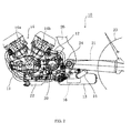
- Fig. 1 illustrates a motorcycle 1 including an exhaust system 10 of a motorcycle in an embodiment according to the invention.
- a V-type four-cylinder engine 14 is supported by a vehicle body frame 26.
- Front exhaust pipes 11 and rear exhaust pipes 12 are extended to the rear of the vehicle body from front cylinders 14a disposed before an engine 14 and rear cylinders 14b disposed behind the engine 14, respectively.
- the respective rear ends of the front and rear exhaust pipes 11 and 12 are collectively joined to an exhaust chamber 13.
- An exhaust muffler 15 is connected with the rear part of the exhaust chamber 13.
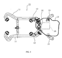
- Figs. 2 and 3 are side and plan views respectively of the exhaust system 10. As illustrated in Figs. 2 and 3, the rear ends of the front exhaust pipes 11 connected with the front cylinders 14a of the V-type engine 14 are joined to the front part of the exhaust chamber 13, and the rear ends of the rear exhaust pipes 12 connected with the rear cylinders 14b of the V-type engine 14 are joined to the upper part of the exhaust chamber 13. Both exhaust gases discharged from the front exhaust pipes 11 and the rear exhaust pipes 12 are unified within the exhaust chamber 13. A catalyst 16 is disposed in the vicinity of a unifying section 25 of the exhaust chamber 13.
- the exhaust chamber 13 is positioned behind an oil pan 22 below the engine 14, and located below the space between a transmission chamber 20 behind the engine 14 and a swing arm 21 supported by the vehicle frame 26 behind the transmission chamber 20.
- the front exhaust pipes 11 extend from the front parts of the front cylinders 14a through the lower part of the V-type engine 14 to be connected with the front part of the exhaust chamber 13.
- the rear exhaust pipes 12 extend from the rear parts of the rear cylinders 14b through the space between the transmission chamber 20 and a support center 24 of the swing arm 21 to be connected with the upper part of the exhaust chamber 13. This layout shortens the length of the rear exhaust pipes 12.
- the rear exhaust pipes 12 have a shorter length to reach the connecting point with the exhaust chamber 13 than that length of the front exhaust pipes 11 so that exhaust gas discharged from the rear cylinders 14b can be introduced to the catalyst 16 contained in the exhaust chamber through the rear exhaust pipes 12 while keeping the highest possible temperature of the exhaust gas. Therefore, the purification function of the catalyst 16 can be efficiently offered by this structure.
- the front part of the exhaust chamber 13 is required to have only a width necessary for connecting with the front exhaust pipes 11.
- the front part of the exhaust chamber 13 can have a reduced width as illustrated in Fig. 3. Accordingly, the exhaust chamber 13 can be positioned closer to the engine, and therefore higher-temperature exhaust gas can be introduced to the catalyst 16 through the rear exhaust pipes 12.
- the front exhaust pipes 11 connected with the front cylinders 14a of the engine 14 have a sufficient exhaust pipe length so as to obtain appropriate function of the engine 14.
- the temperature of the exhaust gas discharged through the front exhaust pipes 11 into the exhaust chamber 13 is lowered, but deterioration of the purifying function of the catalyst 16 can be prevented by unification of the exhaust gas from the front exhaust pipes 11 and high-temperature exhaust gas from the rear exhaust pipes 12 within the exhaust chamber 13.
- the heavy catalyst 16 is positioned within the exhaust chamber 13. As a result, the heavy component of the motorcycle 1 is located closer to the center of gravity of the vehicle body. Accordingly, steering stability of the vehicle can be enhanced.
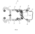
- additional catalysts 17 may be disposed within some parts of the front exhaust pipes 11 as illustrated in Fig. 4.
- high-temperature exhaust gas discharged from the front exhaust pipes 11 is primarily purified by the catalysts 17 disposed within the front exhaust pipes 11 before the temperature of the exhaust gas is lowered.
- the purifying function of the entire exhaust system can be further enhanced.
- the motorcycle according to the embodiments described refers to a vehicle which can turn to other directions while inclining its body, such as motorbike and motor scooter.
- three-wheel vehicles, four-wheel vehicles and vehicles having two or more wheels to define at least either a front wheel set or a rear wheel set, and are classified based on the number of wheels, are all included within the scope of the motorcycle according to the invention.
- An exhaust system of a motorcycle provided according to the invention has enhanced steering stability during running of the vehicle and improved function for purifying exhaust gas.
Landscapes
- Engineering & Computer Science (AREA)
- Chemical & Material Sciences (AREA)
- Combustion & Propulsion (AREA)
- Mechanical Engineering (AREA)
- General Engineering & Computer Science (AREA)
- Health & Medical Sciences (AREA)
- Chemical Kinetics & Catalysis (AREA)
- Toxicology (AREA)
- Exhaust Gas After Treatment (AREA)
- Exhaust Silencers (AREA)
Abstract
Description
- The present invention relates to an exhaust system of a motorcycle, and more particularly to an exhaust system of a motorcycle which has a V-type engine and an exhaust gas purifying function. The invention also relates to a motorcycle including this exhaust system.
- According to a typical structure of an exhaust system of a motorcycle which includes a V-type engine, front exhaust pipes connected with cylinders disposed before an engine and rear exhaust pipes connected with cylinders disposed behind the engine are joined to an exhaust muffler via an exhaust chamber.
- In this layout, both the front exhaust pipes and the rear exhaust pipes collectively joined to the exhaust chamber preferably have their optimum length so as to secure appropriate function of the engine. While the front exhaust pipes sufficiently have the optimum length, the rear exhaust pipes have only a short length to reach the exhaust chamber and therefore cannot easily obtain the same length as that of the front exhaust pipes.
- Prior art references, such as patent reference
JP-A-62-60914 - There has been also a demand for purification of exhaust gas discharged from an exhaust system in addition to the requirement for sufficient performance of the engine. Patent reference
JP-A-59-99020 - Fig. 5 is a vertical cross-sectional plan view of an
exhaust chamber 101 shown inJP-A-59-99020 Front exhaust pipes exhaust chamber 101, andrear exhaust pipes exhaust chamber 101. Therear exhaust pipes exhaust chamber 101 and extend from the cross point. The opening ends of thefront exhaust pipes rear exhaust pipes joint pipes - In this structure, the
rear exhaust pipes front exhaust pipes rear exhaust pipes joint pipes - According to the method shown in
JP-A-59-99020 - Additionally, since the rear exhaust pipes are extended within the exhaust chamber so as to obtain the sufficient length of the rear exhaust pipes, no space for accommodating the catalyst is left within the exhaust chamber. It is therefore difficult to position the catalyst within the exhaust chamber and locate the heavy component of the motorcycle near the center of gravity of the vehicle body.
- It is an object of the invention to provide an exhaust system of a motorcycle which has enhanced steering stability during running of the vehicle and improved function for purifying exhaust gas.
- An exhaust system of a motorcycle according to the invention includes front exhaust pipes adapted to be connected with front cylinders of a V-type engine, rear exhaust pipes adapted to be connected with rear cylinders of the engine, and an exhaust chamber connected with the respective rear ends of the front exhaust pipes and the rear exhaust pipes. The rear ends of the front exhaust pipes are connected with the front part of the exhaust chamber. The rear ends of the rear exhaust pipes are connected with the upper part of the exhaust chamber. Exhaust gases discharged from the front exhaust pipes and the rear exhaust pipes are unified within the exhaust chamber, and a catalyst is disposed in the vicinity of the unifying section. The length of the rear exhaust pipes is shorter than the length of the front exhaust pipes.
- In a preferred embodiment, an exhaust muffler is connected with the rear part of the exhaust chamber.
- In one embodiment, one or more catalysts may be disposed within at least one of the front exhaust pipes.
- In a preferable embodiment, the motorcycle includes a vehicle body frame, a transmission chamber provided behind the V-type engine, a swing arm disposed behind the transmission chamber and supported by the vehicle body frame, and an oil pan equipped below the V-type engine. The exhaust chamber is disposed behind the oil pan and below a space defined between the transmission chamber and the swing arm.
- In a preferable embodiment, the front exhaust pipes are adapted to extend from the front parts of the front cylinders through the lower part of the V-type engine to be connected with the front part of the exhaust chamber. The rear exhaust pipes are adapted to extend from the rear parts of the rear cylinders and through a space defined between the transmission chamber and the support center of the swing arm to be connected with the upper part of the exhaust chamber.
- A motorcycle according to the invention includes the exhaust system of a motorcycle mentioned above.
- In the layout of an exhaust system of a motorcycle according to the invention, rear exhaust pipes having a shorter length than that of front exhaust pipes are connected with an exhaust chamber so that exhaust gas can be introduced to a catalyst contained within an exhaust chamber without lowering the temperature of the exhaust gas. Thus, efficient purifying function can be offered by this structure. In addition, since the catalyst is contained within the exhaust chamber, the heavy component of the motorcycle is located near the center of gravity. As a result, steering stability of the vehicle can be enhanced.
- An embodiment according to the invention is hereinafter described with reference to the accompanying drawings, in which:
- Fig. 1 illustrates a motorcycle including an exhaust system of a motorcycle in an embodiment according to the invention;
- Fig. 2 is a side view showing a basic structure of the exhaust system of a motorcycle in the embodiment according to the invention;
- Fig. 3 is a plan view showing the basic structure of the exhaust system of a motorcycle in the embodiment according to the invention;
- Fig. 4 is a plan view showing a structure of an exhaust system of a motorcycle in another embodiment according to the invention; and
- Fig. 5 is a vertical cross-sectional plan view showing a structure of a known exhaust chamber of a motorcycle in a related art.
- For simplifying the explanation, similar reference numerals are given to components having substantially similar functions in the figures. The invention is not limited to this embodiment.
- Fig. 1 illustrates a motorcycle 1 including an
exhaust system 10 of a motorcycle in an embodiment according to the invention. - As illustrated in Fig. 1, a V-type four-
cylinder engine 14 is supported by avehicle body frame 26.Front exhaust pipes 11 andrear exhaust pipes 12 are extended to the rear of the vehicle body fromfront cylinders 14a disposed before anengine 14 andrear cylinders 14b disposed behind theengine 14, respectively. The respective rear ends of the front andrear exhaust pipes exhaust chamber 13. Anexhaust muffler 15 is connected with the rear part of theexhaust chamber 13. - The basic structure of the
exhaust system 10 of the motorcycle according to the invention is discussed with reference to Figs. 2 and 3. - Figs. 2 and 3 are side and plan views respectively of the
exhaust system 10. As illustrated in Figs. 2 and 3, the rear ends of thefront exhaust pipes 11 connected with thefront cylinders 14a of the V-type engine 14 are joined to the front part of theexhaust chamber 13, and the rear ends of therear exhaust pipes 12 connected with therear cylinders 14b of the V-type engine 14 are joined to the upper part of theexhaust chamber 13. Both exhaust gases discharged from thefront exhaust pipes 11 and therear exhaust pipes 12 are unified within theexhaust chamber 13. Acatalyst 16 is disposed in the vicinity of a unifyingsection 25 of theexhaust chamber 13. - As illustrated in Fig. 2, the
exhaust chamber 13 is positioned behind anoil pan 22 below theengine 14, and located below the space between atransmission chamber 20 behind theengine 14 and aswing arm 21 supported by thevehicle frame 26 behind thetransmission chamber 20. - As illustrated in Fig. 2, the
front exhaust pipes 11 extend from the front parts of thefront cylinders 14a through the lower part of the V-type engine 14 to be connected with the front part of theexhaust chamber 13. Therear exhaust pipes 12 extend from the rear parts of therear cylinders 14b through the space between thetransmission chamber 20 and asupport center 24 of theswing arm 21 to be connected with the upper part of theexhaust chamber 13. This layout shortens the length of therear exhaust pipes 12. - In the
exhaust system 10 according to the invention, therear exhaust pipes 12 have a shorter length to reach the connecting point with theexhaust chamber 13 than that length of thefront exhaust pipes 11 so that exhaust gas discharged from therear cylinders 14b can be introduced to thecatalyst 16 contained in the exhaust chamber through therear exhaust pipes 12 while keeping the highest possible temperature of the exhaust gas. Therefore, the purification function of thecatalyst 16 can be efficiently offered by this structure. - Since the
rear exhaust pipes 12 are connected with the upper part of theexhaust chamber 13, the front part of theexhaust chamber 13 is required to have only a width necessary for connecting with thefront exhaust pipes 11. Thus, the front part of theexhaust chamber 13 can have a reduced width as illustrated in Fig. 3. Accordingly, theexhaust chamber 13 can be positioned closer to the engine, and therefore higher-temperature exhaust gas can be introduced to thecatalyst 16 through therear exhaust pipes 12. - It is preferable that the
front exhaust pipes 11 connected with thefront cylinders 14a of theengine 14 have a sufficient exhaust pipe length so as to obtain appropriate function of theengine 14. In this case, the temperature of the exhaust gas discharged through thefront exhaust pipes 11 into theexhaust chamber 13 is lowered, but deterioration of the purifying function of thecatalyst 16 can be prevented by unification of the exhaust gas from thefront exhaust pipes 11 and high-temperature exhaust gas from therear exhaust pipes 12 within theexhaust chamber 13. - In the
exhaust system 10 according to the invention, theheavy catalyst 16 is positioned within theexhaust chamber 13. As a result, the heavy component of the motorcycle 1 is located closer to the center of gravity of the vehicle body. Accordingly, steering stability of the vehicle can be enhanced. - The invention is not limited to the preferred embodiment having been depicted and described herein, but obviously various modifications and changes may be given to the invention. For example,
additional catalysts 17 may be disposed within some parts of thefront exhaust pipes 11 as illustrated in Fig. 4. In this case, high-temperature exhaust gas discharged from thefront exhaust pipes 11 is primarily purified by thecatalysts 17 disposed within thefront exhaust pipes 11 before the temperature of the exhaust gas is lowered. Thus, the purifying function of the entire exhaust system can be further enhanced. - The motorcycle according to the embodiments described refers to a vehicle which can turn to other directions while inclining its body, such as motorbike and motor scooter. Thus, three-wheel vehicles, four-wheel vehicles and vehicles having two or more wheels to define at least either a front wheel set or a rear wheel set, and are classified based on the number of wheels, are all included within the scope of the motorcycle according to the invention.
- An exhaust system of a motorcycle provided according to the invention has enhanced steering stability during running of the vehicle and improved function for purifying exhaust gas.
-
- 1
- motorcycle
- 10
- exhaust system
- 11
- front exhaust pipe
- 12
- rear exhaust pipe
- 13
- exhaust chamber
- 14
- V-type engine
- 14a
- front cylinder
- 14b
- rear cylinder
- 15
- exhaust muffler
- 16, 17
- catalyst
- 20
- transmission chamber
- 21
- swing arm
- 22
- oil pan
- 25
- unifying section
- 26
- vehicle body frame
- 101
- exhaust chamber
- 102a, 102b
- front exhaust pipe
- 103a, 103b
- rear exhaust pipe
- 104a, 104b
- joint pipe
Claims (9)
- An exhaust system (10) of a motorcycle (1), comprising:a front exhaust pipe (11) adapted to be connected with a front cylinder (14a) of a V-type engine (14);a rear exhaust pipe (12) adapted to be connected with a rear cylinder (14b) of the engine (14); andan exhaust chamber (13) connected with the respective rear ends of the front exhaust pipe (11) and the rear exhaust pipe (12), characterized in that:wherein exhaust gases discharged from the front exhaust pipe (11) and the rear exhaust pipe (12) are unified within the exhaust chamber (13), and a catalyst is disposed in the vicinity of a unifying section (25); andthe rear end of the front exhaust pipe (11) is connected with a front part of the exhaust chamber (13);the rear end of the rear exhaust pipe (12) is connected with an upper part of the exhaust chamber (13);
the length of the rear exhaust pipe (12) is shorter than the length of the front exhaust pipe (11). - An exhaust system (10) of a motorcycle (1) according to claim 1, characterized in that an exhaust muffler (15) is connected with a rear part of the exhaust chamber (13).
- An exhaust system (10) of a motorcycle (1) according to claim 1 or 2, characterized in that a catalyst (17) is disposed within the front exhaust pipe (11).
- An exhaust system (10) of a motorcycle (1) according to claim 1, 2 or 3, characterized in that:the motorcycle (1) includes a vehicle body frame (26), a transmission chamber (20) provided behind the V-type engine (14), a swing arm (21) disposed behind the transmission chamber (20) and supported by the vehicle body frame (26), and an oil pan (22) equipped below the V-type engine (14); andthe exhaust chamber (13) is disposed behind the oil pan (22) and below a space defined between the transmission chamber (20) and the swing arm (21).
- An exhaust system (10) of a motorcycle (1) according to claim 4, characterized in that:the front exhaust pipe (11) is adapted to extend from a front part of the front cylinder (14a) through the lower part of the V-type engine (14) to be connected with the front part of the exhaust chamber (13); andthe rear exhaust pipe (12) is adapted to extend from a rear part of the rear cylinder (14b) and through a space defined between the transmission chamber (20) and the support center (24) of the swing arm (21) to be connected with the upper part of the exhaust chamber (13).
- An exhaust system (10) of a motorcycle (1) according to any preceding claim, comprising a plurality of front exhaust pipes (11) adapted to be connected to at least one front cylinder (14a) of the engine (14).
- An exhaust system (10) of a motorcycle (1) according to claim 6, characterized in that a catalyst (17) is disposed within at least one of the front exhaust pipes (11).
- An exhaust system (10) of a motorcycle (1) according to any preceding claim, comprising a plurality of rear exhaust pipes (12) adapted to be connected to at least one rear cylinder (14b) of the engine (14).
- A motorcycle (1) comprising an exhaust system (10 according to any one of claims 1 to 8.
Applications Claiming Priority (1)
| Application Number | Priority Date | Filing Date | Title |
|---|---|---|---|
| JP2005294629A JP2007100664A (en) | 2005-10-07 | 2005-10-07 | Motorcycle exhaust system and motorcycle equipped with exhaust system |
Publications (2)
| Publication Number | Publication Date |
|---|---|
| EP1772601A1 true EP1772601A1 (en) | 2007-04-11 |
| EP1772601B1 EP1772601B1 (en) | 2010-07-21 |
Family
ID=37453382
Family Applications (1)
| Application Number | Title | Priority Date | Filing Date |
|---|---|---|---|
| EP06254600A Ceased EP1772601B1 (en) | 2005-10-07 | 2006-09-04 | Motorcycle including an exhaust system |
Country Status (6)
| Country | Link |
|---|---|
| US (1) | US7637349B2 (en) |
| EP (1) | EP1772601B1 (en) |
| JP (1) | JP2007100664A (en) |
| CN (1) | CN1944977B (en) |
| AT (1) | ATE475003T1 (en) |
| DE (1) | DE602006015581D1 (en) |
Cited By (2)
| Publication number | Priority date | Publication date | Assignee | Title |
|---|---|---|---|---|
| EP2319749A2 (en) | 2009-11-06 | 2011-05-11 | Bajaj Auto Limited | An exhaust system for a motorcycle |
| EP2784275A1 (en) * | 2013-03-30 | 2014-10-01 | Honda Motor Co., Ltd. | Exhaust pipe structure for internal combustion engine |
Families Citing this family (22)
| Publication number | Priority date | Publication date | Assignee | Title |
|---|---|---|---|---|
| JP2007100664A (en) * | 2005-10-07 | 2007-04-19 | Yamaha Motor Co Ltd | Motorcycle exhaust system and motorcycle equipped with exhaust system |
| JP2008195113A (en) * | 2007-02-08 | 2008-08-28 | Yamaha Motor Co Ltd | Motorcycle exhaust system and motorcycle |
| JP2009241922A (en) * | 2007-12-28 | 2009-10-22 | Yamaha Motor Co Ltd | Saddle riding vehicle |
| JP2009281375A (en) * | 2008-04-22 | 2009-12-03 | Yamaha Motor Co Ltd | Motorcycle |
| JP3154637U (en) * | 2008-08-08 | 2009-10-22 | ヤマハ発動機株式会社 | Saddle riding type vehicle |
| USD612312S1 (en) * | 2009-01-27 | 2010-03-23 | Brock Davidson Enterprises | Elliptical motorcycle megaphone exhaust system |
| USD612313S1 (en) * | 2009-01-27 | 2010-03-23 | Brock Davidson Enterprises | Motorcycle megaphone exhaust system discharge opening |
| US8701823B2 (en) * | 2011-02-14 | 2014-04-22 | Honda Motor Co., Ltd. | Exhaust system for motorcycle |
| US8622040B2 (en) * | 2012-03-20 | 2014-01-07 | GM Global Technology Operations LLC | Compact transmission fluid heater |
| US8827035B2 (en) | 2012-12-03 | 2014-09-09 | Ford Global Technologies, Llc | Conformal transverse muffler |
| US9021804B2 (en) * | 2013-03-14 | 2015-05-05 | Ford Global Technologies, Llc | Self-sustaining low pressure EGR and exhaust system |
| JP2014234735A (en) * | 2013-05-31 | 2014-12-15 | ヤマハ発動機株式会社 | Motorcycle |
| US9121320B2 (en) * | 2013-08-20 | 2015-09-01 | Tenneco Automotive Operating Company Inc. | Tailor to fit muffler |
| JP6149705B2 (en) * | 2013-11-19 | 2017-06-21 | スズキ株式会社 | Motorcycle exhaust system |
| USD747746S1 (en) * | 2014-09-26 | 2016-01-19 | Charles Fenn Giordano | Exhaust component |
| US11365658B2 (en) | 2017-10-05 | 2022-06-21 | Tenneco Automotive Operating Company Inc. | Acoustically tuned muffler |
| DE102018124198A1 (en) | 2017-10-05 | 2019-04-11 | Tenneco Automotive Operating Company Inc. | Acoustically tuned silencer |
| US11199116B2 (en) | 2017-12-13 | 2021-12-14 | Tenneco Automotive Operating Company Inc. | Acoustically tuned muffler |
| US11268429B2 (en) | 2019-01-17 | 2022-03-08 | Tenneco Automotive Operating Company Inc. | Diffusion surface alloyed metal exhaust component with inwardly turned edges |
| US11268430B2 (en) | 2019-01-17 | 2022-03-08 | Tenneco Automotive Operating Company Inc. | Diffusion surface alloyed metal exhaust component with welded edges |
| US10975743B1 (en) | 2020-03-13 | 2021-04-13 | Tenneco Automotive Operating Company Inc. | Vehicle exhaust component |
| JP2025058517A (en) * | 2023-09-28 | 2025-04-09 | カワサキモータース株式会社 | Saddle riding vehicle |
Citations (6)
| Publication number | Priority date | Publication date | Assignee | Title |
|---|---|---|---|---|
| JPS5920518A (en) * | 1982-07-26 | 1984-02-02 | Yamaha Motor Co Ltd | Exhaust purifier for motorcycle |
| JPS5999020A (en) | 1982-11-26 | 1984-06-07 | Honda Motor Co Ltd | Motorcycle exhaust chamber |
| JPS5999021A (en) * | 1982-11-26 | 1984-06-07 | Honda Motor Co Ltd | O2-sensor attaching structure for v-type multi-cylinder engine |
| JPS6017220A (en) * | 1983-07-09 | 1985-01-29 | Honda Motor Co Ltd | Engine exhaust purification device for motorcycles |
| DE4040721A1 (en) * | 1989-12-21 | 1991-07-04 | Sebring Auspuff | Silencer unit for four-stroke motorcycle - includes coated catalyst(s) for exhaust gas cleaning |
| JPH11148347A (en) * | 1997-11-12 | 1999-06-02 | Nissan Motor Co Ltd | Exhaust system for V-type internal combustion engine |
Family Cites Families (19)
| Publication number | Priority date | Publication date | Assignee | Title |
|---|---|---|---|---|
| US2940249A (en) * | 1955-10-25 | 1960-06-14 | Volkswagenwerk Ag | Exhaust head for internal combustion engines |
| JPS5090038U (en) * | 1973-12-22 | 1975-07-30 | ||
| JPS5546045A (en) * | 1978-09-29 | 1980-03-31 | Yamaha Motor Co Ltd | Muffler for autobicycle |
| USRE31724E (en) * | 1979-01-18 | 1984-11-06 | Yamaha Hatsudoki Kabushiki Kaisha | Motorcycle exhaust systems |
| JPS5733020A (en) * | 1980-08-04 | 1982-02-23 | Honda Motor Co Ltd | Supercharger device in autobicycle |
| JPS5849518A (en) * | 1981-09-19 | 1983-03-23 | Honda Motor Co Ltd | Exhauster for motor cycle |
| JPS5885720A (en) * | 1981-11-13 | 1983-05-23 | Yamaha Motor Co Ltd | Exhaust system of motor cycle |
| JPS58101825A (en) * | 1981-12-11 | 1983-06-17 | Yamaha Motor Co Ltd | Autobicycle mounted with v-type engine |
| JPS57167825A (en) * | 1982-03-11 | 1982-10-15 | Yamaha Motor Co Ltd | Exhaust device of autobicycle |
| JPS58158311A (en) * | 1982-03-15 | 1983-09-20 | Yamaha Motor Co Ltd | Exhaust device for motorcycle |
| JPS58224812A (en) * | 1982-06-24 | 1983-12-27 | Yamaha Motor Co Ltd | Exhaust tube device for motorcycle |
| US4522282A (en) * | 1982-09-27 | 1985-06-11 | Yamaha Hatsudoki Kabushiki Kaisha | Exhaust system for motorcycle |
| JPS6078924A (en) * | 1983-10-03 | 1985-05-04 | Daikin Ind Ltd | Production of octafluoropropane |
| JPS6260914A (en) | 1985-09-09 | 1987-03-17 | Honda Motor Co Ltd | Exhaust device for motorbicycle |
| JPH0440721A (en) | 1990-06-06 | 1992-02-12 | Nec Corp | Control circuit for recognition of address |
| JP3242488B2 (en) * | 1993-05-25 | 2001-12-25 | ヤマハ発動機株式会社 | Exhaust system with catalyst for motorcycle |
| DE10341642B3 (en) * | 2003-09-10 | 2005-04-28 | Porsche Ag | Aerodynamically designed trim part for the underside of a motor vehicle |
| US6962225B2 (en) * | 2004-04-07 | 2005-11-08 | Honda Motor Company, Ltd. | Pipe system for a motorcycle |
| JP2007100664A (en) * | 2005-10-07 | 2007-04-19 | Yamaha Motor Co Ltd | Motorcycle exhaust system and motorcycle equipped with exhaust system |
-
2005
- 2005-10-07 JP JP2005294629A patent/JP2007100664A/en active Pending
-
2006
- 2006-09-04 EP EP06254600A patent/EP1772601B1/en not_active Ceased
- 2006-09-04 DE DE602006015581T patent/DE602006015581D1/en active Active
- 2006-09-04 AT AT06254600T patent/ATE475003T1/en not_active IP Right Cessation
- 2006-09-29 CN CN2006101524334A patent/CN1944977B/en not_active Expired - Fee Related
- 2006-10-03 US US11/538,355 patent/US7637349B2/en not_active Expired - Fee Related
Patent Citations (6)
| Publication number | Priority date | Publication date | Assignee | Title |
|---|---|---|---|---|
| JPS5920518A (en) * | 1982-07-26 | 1984-02-02 | Yamaha Motor Co Ltd | Exhaust purifier for motorcycle |
| JPS5999020A (en) | 1982-11-26 | 1984-06-07 | Honda Motor Co Ltd | Motorcycle exhaust chamber |
| JPS5999021A (en) * | 1982-11-26 | 1984-06-07 | Honda Motor Co Ltd | O2-sensor attaching structure for v-type multi-cylinder engine |
| JPS6017220A (en) * | 1983-07-09 | 1985-01-29 | Honda Motor Co Ltd | Engine exhaust purification device for motorcycles |
| DE4040721A1 (en) * | 1989-12-21 | 1991-07-04 | Sebring Auspuff | Silencer unit for four-stroke motorcycle - includes coated catalyst(s) for exhaust gas cleaning |
| JPH11148347A (en) * | 1997-11-12 | 1999-06-02 | Nissan Motor Co Ltd | Exhaust system for V-type internal combustion engine |
Cited By (3)
| Publication number | Priority date | Publication date | Assignee | Title |
|---|---|---|---|---|
| EP2319749A2 (en) | 2009-11-06 | 2011-05-11 | Bajaj Auto Limited | An exhaust system for a motorcycle |
| EP2784275A1 (en) * | 2013-03-30 | 2014-10-01 | Honda Motor Co., Ltd. | Exhaust pipe structure for internal combustion engine |
| US9328647B2 (en) | 2013-03-30 | 2016-05-03 | Honda Motor Co., Ltd. | Exhaust pipe structure for internal combustion engine |
Also Published As
| Publication number | Publication date |
|---|---|
| DE602006015581D1 (en) | 2010-09-02 |
| JP2007100664A (en) | 2007-04-19 |
| CN1944977A (en) | 2007-04-11 |
| US20070102224A1 (en) | 2007-05-10 |
| CN1944977B (en) | 2011-09-28 |
| US7637349B2 (en) | 2009-12-29 |
| EP1772601B1 (en) | 2010-07-21 |
| ATE475003T1 (en) | 2010-08-15 |
Similar Documents
| Publication | Publication Date | Title |
|---|---|---|
| EP1772601B1 (en) | Motorcycle including an exhaust system | |
| CN104093912B (en) | Bulldozer | |
| JP4850119B2 (en) | Vehicle exhaust system | |
| JP3304508B2 (en) | Exhaust gas purification device for motorcycle | |
| EP1921287B1 (en) | Vehicle | |
| JP5019166B2 (en) | Vehicle exhaust system | |
| EP1609963B1 (en) | Exhaust gas purifying apparatus of motorcycle | |
| JP7155860B2 (en) | Silencer structure for straddle-type vehicle | |
| EP1749989B1 (en) | Exhaust system and saddle-ride type vehicle | |
| EP2031200A1 (en) | An exhaust gas purifying apparatus for a motor vehicle and a motor vehicle equipped with such an exhaust gas purifying apparatus | |
| EP2011975B1 (en) | An exhaust gas purifying apparatus for a motor vehicle and motor vehicle | |
| JP2018115653A (en) | Engine exhaust system | |
| EP4026993B1 (en) | Exhaust device | |
| CN114753912B (en) | Exhaust device | |
| JP2005188316A (en) | Motorcycle exhaust system | |
| EP1933011B1 (en) | Motorcycle | |
| US9815521B2 (en) | Exhaust system of saddle-ride type vehicle | |
| JP2006103375A (en) | Muffler mounting structure | |
| KR20140026829A (en) | Fixing structure of exhaust gas after treatment device | |
| JP4917464B2 (en) | Vehicle exhaust system | |
| EP4026991B1 (en) | Straddle-type vehicle | |
| JP2006327586A5 (en) | ||
| EP3381729B1 (en) | Engine mounting structure |
Legal Events
| Date | Code | Title | Description |
|---|---|---|---|
| PUAI | Public reference made under article 153(3) epc to a published international application that has entered the european phase |
Free format text: ORIGINAL CODE: 0009012 |
|
| AK | Designated contracting states |
Kind code of ref document: A1 Designated state(s): AT BE BG CH CY CZ DE DK EE ES FI FR GB GR HU IE IS IT LI LT LU LV MC NL PL PT RO SE SI SK TR |
|
| AX | Request for extension of the european patent |
Extension state: AL BA HR MK YU |
|
| 17P | Request for examination filed |
Effective date: 20071011 |
|
| 17Q | First examination report despatched |
Effective date: 20071109 |
|
| AKX | Designation fees paid |
Designated state(s): AT BE BG CH CY CZ DE DK EE ES FI FR GB GR HU IE IS IT LI LT LU LV MC NL PL PT RO SE SI SK TR |
|
| GRAP | Despatch of communication of intention to grant a patent |
Free format text: ORIGINAL CODE: EPIDOSNIGR1 |
|
| RTI1 | Title (correction) |
Free format text: MOTORCYCLE INCLUDING AN EXHAUST SYSTEM |
|
| RIC1 | Information provided on ipc code assigned before grant |
Ipc: F01N 13/08 20100101AFI20100202BHEP Ipc: F01N 3/28 20060101ALI20100202BHEP |
|
| GRAS | Grant fee paid |
Free format text: ORIGINAL CODE: EPIDOSNIGR3 |
|
| GRAA | (expected) grant |
Free format text: ORIGINAL CODE: 0009210 |
|
| AK | Designated contracting states |
Kind code of ref document: B1 Designated state(s): AT BE BG CH CY CZ DE DK EE ES FI FR GB GR HU IE IS IT LI LT LU LV MC NL PL PT RO SE SI SK TR |
|
| REG | Reference to a national code |
Ref country code: GB Ref legal event code: FG4D |
|
| REG | Reference to a national code |
Ref country code: CH Ref legal event code: EP |
|
| REG | Reference to a national code |
Ref country code: IE Ref legal event code: FG4D |
|
| REF | Corresponds to: |
Ref document number: 602006015581 Country of ref document: DE Date of ref document: 20100902 Kind code of ref document: P |
|
| REG | Reference to a national code |
Ref country code: NL Ref legal event code: VDEP Effective date: 20100721 |
|
| LTIE | Lt: invalidation of european patent or patent extension |
Effective date: 20100721 |
|
| PG25 | Lapsed in a contracting state [announced via postgrant information from national office to epo] |
Ref country code: NL Free format text: LAPSE BECAUSE OF FAILURE TO SUBMIT A TRANSLATION OF THE DESCRIPTION OR TO PAY THE FEE WITHIN THE PRESCRIBED TIME-LIMIT Effective date: 20100721 Ref country code: LT Free format text: LAPSE BECAUSE OF FAILURE TO SUBMIT A TRANSLATION OF THE DESCRIPTION OR TO PAY THE FEE WITHIN THE PRESCRIBED TIME-LIMIT Effective date: 20100721 Ref country code: FI Free format text: LAPSE BECAUSE OF FAILURE TO SUBMIT A TRANSLATION OF THE DESCRIPTION OR TO PAY THE FEE WITHIN THE PRESCRIBED TIME-LIMIT Effective date: 20100721 Ref country code: AT Free format text: LAPSE BECAUSE OF FAILURE TO SUBMIT A TRANSLATION OF THE DESCRIPTION OR TO PAY THE FEE WITHIN THE PRESCRIBED TIME-LIMIT Effective date: 20100721 |
|
| PG25 | Lapsed in a contracting state [announced via postgrant information from national office to epo] |
Ref country code: SI Free format text: LAPSE BECAUSE OF FAILURE TO SUBMIT A TRANSLATION OF THE DESCRIPTION OR TO PAY THE FEE WITHIN THE PRESCRIBED TIME-LIMIT Effective date: 20100721 Ref country code: PT Free format text: LAPSE BECAUSE OF FAILURE TO SUBMIT A TRANSLATION OF THE DESCRIPTION OR TO PAY THE FEE WITHIN THE PRESCRIBED TIME-LIMIT Effective date: 20101122 Ref country code: PL Free format text: LAPSE BECAUSE OF FAILURE TO SUBMIT A TRANSLATION OF THE DESCRIPTION OR TO PAY THE FEE WITHIN THE PRESCRIBED TIME-LIMIT Effective date: 20100721 Ref country code: IS Free format text: LAPSE BECAUSE OF FAILURE TO SUBMIT A TRANSLATION OF THE DESCRIPTION OR TO PAY THE FEE WITHIN THE PRESCRIBED TIME-LIMIT Effective date: 20101121 Ref country code: CY Free format text: LAPSE BECAUSE OF FAILURE TO SUBMIT A TRANSLATION OF THE DESCRIPTION OR TO PAY THE FEE WITHIN THE PRESCRIBED TIME-LIMIT Effective date: 20100721 Ref country code: BG Free format text: LAPSE BECAUSE OF FAILURE TO SUBMIT A TRANSLATION OF THE DESCRIPTION OR TO PAY THE FEE WITHIN THE PRESCRIBED TIME-LIMIT Effective date: 20101021 |
|
| PG25 | Lapsed in a contracting state [announced via postgrant information from national office to epo] |
Ref country code: SE Free format text: LAPSE BECAUSE OF FAILURE TO SUBMIT A TRANSLATION OF THE DESCRIPTION OR TO PAY THE FEE WITHIN THE PRESCRIBED TIME-LIMIT Effective date: 20100721 Ref country code: LV Free format text: LAPSE BECAUSE OF FAILURE TO SUBMIT A TRANSLATION OF THE DESCRIPTION OR TO PAY THE FEE WITHIN THE PRESCRIBED TIME-LIMIT Effective date: 20100721 Ref country code: BE Free format text: LAPSE BECAUSE OF FAILURE TO SUBMIT A TRANSLATION OF THE DESCRIPTION OR TO PAY THE FEE WITHIN THE PRESCRIBED TIME-LIMIT Effective date: 20100721 Ref country code: GR Free format text: LAPSE BECAUSE OF FAILURE TO SUBMIT A TRANSLATION OF THE DESCRIPTION OR TO PAY THE FEE WITHIN THE PRESCRIBED TIME-LIMIT Effective date: 20101022 |
|
| PG25 | Lapsed in a contracting state [announced via postgrant information from national office to epo] |
Ref country code: MC Free format text: LAPSE BECAUSE OF NON-PAYMENT OF DUE FEES Effective date: 20100930 Ref country code: DK Free format text: LAPSE BECAUSE OF FAILURE TO SUBMIT A TRANSLATION OF THE DESCRIPTION OR TO PAY THE FEE WITHIN THE PRESCRIBED TIME-LIMIT Effective date: 20100721 |
|
| REG | Reference to a national code |
Ref country code: CH Ref legal event code: PL |
|
| PLBE | No opposition filed within time limit |
Free format text: ORIGINAL CODE: 0009261 |
|
| STAA | Information on the status of an ep patent application or granted ep patent |
Free format text: STATUS: NO OPPOSITION FILED WITHIN TIME LIMIT |
|
| PG25 | Lapsed in a contracting state [announced via postgrant information from national office to epo] |
Ref country code: CZ Free format text: LAPSE BECAUSE OF FAILURE TO SUBMIT A TRANSLATION OF THE DESCRIPTION OR TO PAY THE FEE WITHIN THE PRESCRIBED TIME-LIMIT Effective date: 20100721 Ref country code: RO Free format text: LAPSE BECAUSE OF FAILURE TO SUBMIT A TRANSLATION OF THE DESCRIPTION OR TO PAY THE FEE WITHIN THE PRESCRIBED TIME-LIMIT Effective date: 20100721 Ref country code: EE Free format text: LAPSE BECAUSE OF FAILURE TO SUBMIT A TRANSLATION OF THE DESCRIPTION OR TO PAY THE FEE WITHIN THE PRESCRIBED TIME-LIMIT Effective date: 20100721 Ref country code: SK Free format text: LAPSE BECAUSE OF FAILURE TO SUBMIT A TRANSLATION OF THE DESCRIPTION OR TO PAY THE FEE WITHIN THE PRESCRIBED TIME-LIMIT Effective date: 20100721 Ref country code: IT Free format text: LAPSE BECAUSE OF FAILURE TO SUBMIT A TRANSLATION OF THE DESCRIPTION OR TO PAY THE FEE WITHIN THE PRESCRIBED TIME-LIMIT Effective date: 20100721 |
|
| 26N | No opposition filed |
Effective date: 20110426 |
|
| PG25 | Lapsed in a contracting state [announced via postgrant information from national office to epo] |
Ref country code: ES Free format text: LAPSE BECAUSE OF FAILURE TO SUBMIT A TRANSLATION OF THE DESCRIPTION OR TO PAY THE FEE WITHIN THE PRESCRIBED TIME-LIMIT Effective date: 20101101 |
|
| PG25 | Lapsed in a contracting state [announced via postgrant information from national office to epo] |
Ref country code: CH Free format text: LAPSE BECAUSE OF NON-PAYMENT OF DUE FEES Effective date: 20100930 Ref country code: IE Free format text: LAPSE BECAUSE OF NON-PAYMENT OF DUE FEES Effective date: 20100904 Ref country code: LI Free format text: LAPSE BECAUSE OF NON-PAYMENT OF DUE FEES Effective date: 20100930 |
|
| REG | Reference to a national code |
Ref country code: DE Ref legal event code: R097 Ref document number: 602006015581 Country of ref document: DE Effective date: 20110426 |
|
| PG25 | Lapsed in a contracting state [announced via postgrant information from national office to epo] |
Ref country code: HU Free format text: LAPSE BECAUSE OF FAILURE TO SUBMIT A TRANSLATION OF THE DESCRIPTION OR TO PAY THE FEE WITHIN THE PRESCRIBED TIME-LIMIT Effective date: 20110122 Ref country code: LU Free format text: LAPSE BECAUSE OF NON-PAYMENT OF DUE FEES Effective date: 20100904 |
|
| PG25 | Lapsed in a contracting state [announced via postgrant information from national office to epo] |
Ref country code: TR Free format text: LAPSE BECAUSE OF FAILURE TO SUBMIT A TRANSLATION OF THE DESCRIPTION OR TO PAY THE FEE WITHIN THE PRESCRIBED TIME-LIMIT Effective date: 20100721 |
|
| REG | Reference to a national code |
Ref country code: FR Ref legal event code: PLFP Year of fee payment: 11 |
|
| REG | Reference to a national code |
Ref country code: FR Ref legal event code: PLFP Year of fee payment: 12 |
|
| REG | Reference to a national code |
Ref country code: FR Ref legal event code: PLFP Year of fee payment: 13 |
|
| PGFP | Annual fee paid to national office [announced via postgrant information from national office to epo] |
Ref country code: FR Payment date: 20200914 Year of fee payment: 15 Ref country code: DE Payment date: 20200925 Year of fee payment: 15 Ref country code: GB Payment date: 20200922 Year of fee payment: 15 |
|
| REG | Reference to a national code |
Ref country code: DE Ref legal event code: R119 Ref document number: 602006015581 Country of ref document: DE |
|
| GBPC | Gb: european patent ceased through non-payment of renewal fee |
Effective date: 20210904 |
|
| PG25 | Lapsed in a contracting state [announced via postgrant information from national office to epo] |
Ref country code: GB Free format text: LAPSE BECAUSE OF NON-PAYMENT OF DUE FEES Effective date: 20210904 Ref country code: FR Free format text: LAPSE BECAUSE OF NON-PAYMENT OF DUE FEES Effective date: 20210930 Ref country code: DE Free format text: LAPSE BECAUSE OF NON-PAYMENT OF DUE FEES Effective date: 20220401 |