EP1772364A1 - Bicycle shift operating device - Google Patents
Bicycle shift operating device Download PDFInfo
- Publication number
- EP1772364A1 EP1772364A1 EP06010554A EP06010554A EP1772364A1 EP 1772364 A1 EP1772364 A1 EP 1772364A1 EP 06010554 A EP06010554 A EP 06010554A EP 06010554 A EP06010554 A EP 06010554A EP 1772364 A1 EP1772364 A1 EP 1772364A1
- Authority
- EP
- European Patent Office
- Prior art keywords
- action
- input member
- shaft
- shift operating
- operating device
- Prior art date
- Legal status (The legal status is an assumption and is not a legal conclusion. Google has not performed a legal analysis and makes no representation as to the accuracy of the status listed.)
- Granted
Links
Images









Classifications
-
- B—PERFORMING OPERATIONS; TRANSPORTING
- B62—LAND VEHICLES FOR TRAVELLING OTHERWISE THAN ON RAILS
- B62K—CYCLES; CYCLE FRAMES; CYCLE STEERING DEVICES; RIDER-OPERATED TERMINAL CONTROLS SPECIALLY ADAPTED FOR CYCLES; CYCLE AXLE SUSPENSIONS; CYCLE SIDECARS, FORECARS, OR THE LIKE
- B62K23/00—Rider-operated controls specially adapted for cycles, i.e. means for initiating control operations, e.g. levers, grips
- B62K23/02—Rider-operated controls specially adapted for cycles, i.e. means for initiating control operations, e.g. levers, grips hand actuated
- B62K23/06—Levers
-
- B—PERFORMING OPERATIONS; TRANSPORTING
- B62—LAND VEHICLES FOR TRAVELLING OTHERWISE THAN ON RAILS
- B62M—RIDER PROPULSION OF WHEELED VEHICLES OR SLEDGES; POWERED PROPULSION OF SLEDGES OR SINGLE-TRACK CYCLES; TRANSMISSIONS SPECIALLY ADAPTED FOR SUCH VEHICLES
- B62M25/00—Actuators for gearing speed-change mechanisms specially adapted for cycles
- B62M25/02—Actuators for gearing speed-change mechanisms specially adapted for cycles with mechanical transmitting systems, e.g. cables, levers
- B62M25/04—Actuators for gearing speed-change mechanisms specially adapted for cycles with mechanical transmitting systems, e.g. cables, levers hand actuated
-
- Y—GENERAL TAGGING OF NEW TECHNOLOGICAL DEVELOPMENTS; GENERAL TAGGING OF CROSS-SECTIONAL TECHNOLOGIES SPANNING OVER SEVERAL SECTIONS OF THE IPC; TECHNICAL SUBJECTS COVERED BY FORMER USPC CROSS-REFERENCE ART COLLECTIONS [XRACs] AND DIGESTS
- Y10—TECHNICAL SUBJECTS COVERED BY FORMER USPC
- Y10T—TECHNICAL SUBJECTS COVERED BY FORMER US CLASSIFICATION
- Y10T74/00—Machine element or mechanism
- Y10T74/20—Control lever and linkage systems
- Y10T74/20012—Multiple controlled elements
- Y10T74/20018—Transmission control
- Y10T74/20037—Occupant propelled vehicle
- Y10T74/20043—Transmission controlled by flexible cable
-
- Y—GENERAL TAGGING OF NEW TECHNOLOGICAL DEVELOPMENTS; GENERAL TAGGING OF CROSS-SECTIONAL TECHNOLOGIES SPANNING OVER SEVERAL SECTIONS OF THE IPC; TECHNICAL SUBJECTS COVERED BY FORMER USPC CROSS-REFERENCE ART COLLECTIONS [XRACs] AND DIGESTS
- Y10—TECHNICAL SUBJECTS COVERED BY FORMER USPC
- Y10T—TECHNICAL SUBJECTS COVERED BY FORMER US CLASSIFICATION
- Y10T74/00—Machine element or mechanism
- Y10T74/20—Control lever and linkage systems
- Y10T74/20207—Multiple controlling elements for single controlled element
- Y10T74/20256—Steering and controls assemblies
- Y10T74/20268—Reciprocating control elements
- Y10T74/2028—Handle bar type
- Y10T74/20287—Flexible control element
-
- Y—GENERAL TAGGING OF NEW TECHNOLOGICAL DEVELOPMENTS; GENERAL TAGGING OF CROSS-SECTIONAL TECHNOLOGIES SPANNING OVER SEVERAL SECTIONS OF THE IPC; TECHNICAL SUBJECTS COVERED BY FORMER USPC CROSS-REFERENCE ART COLLECTIONS [XRACs] AND DIGESTS
- Y10—TECHNICAL SUBJECTS COVERED BY FORMER USPC
- Y10T—TECHNICAL SUBJECTS COVERED BY FORMER US CLASSIFICATION
- Y10T74/00—Machine element or mechanism
- Y10T74/20—Control lever and linkage systems
- Y10T74/20396—Hand operated
- Y10T74/20402—Flexible transmitter [e.g., Bowden cable]
-
- Y—GENERAL TAGGING OF NEW TECHNOLOGICAL DEVELOPMENTS; GENERAL TAGGING OF CROSS-SECTIONAL TECHNOLOGIES SPANNING OVER SEVERAL SECTIONS OF THE IPC; TECHNICAL SUBJECTS COVERED BY FORMER USPC CROSS-REFERENCE ART COLLECTIONS [XRACs] AND DIGESTS
- Y10—TECHNICAL SUBJECTS COVERED BY FORMER USPC
- Y10T—TECHNICAL SUBJECTS COVERED BY FORMER US CLASSIFICATION
- Y10T74/00—Machine element or mechanism
- Y10T74/20—Control lever and linkage systems
- Y10T74/20396—Hand operated
- Y10T74/20402—Flexible transmitter [e.g., Bowden cable]
- Y10T74/2042—Flexible transmitter [e.g., Bowden cable] and hand operator
-
- Y—GENERAL TAGGING OF NEW TECHNOLOGICAL DEVELOPMENTS; GENERAL TAGGING OF CROSS-SECTIONAL TECHNOLOGIES SPANNING OVER SEVERAL SECTIONS OF THE IPC; TECHNICAL SUBJECTS COVERED BY FORMER USPC CROSS-REFERENCE ART COLLECTIONS [XRACs] AND DIGESTS
- Y10—TECHNICAL SUBJECTS COVERED BY FORMER USPC
- Y10T—TECHNICAL SUBJECTS COVERED BY FORMER US CLASSIFICATION
- Y10T74/00—Machine element or mechanism
- Y10T74/20—Control lever and linkage systems
- Y10T74/20396—Hand operated
- Y10T74/20402—Flexible transmitter [e.g., Bowden cable]
- Y10T74/2042—Flexible transmitter [e.g., Bowden cable] and hand operator
- Y10T74/20438—Single rotatable lever [e.g., for bicycle brake or derailleur]
Definitions
- the present invention relates to an operating device, and particularly relates to a bicycle shift operating device which is mounted to a bicycle.
- the shift cable When the winding lever is operated in the pressing direction by a thumb in the latter prior art, the shift cable is pulled in the winding direction by one step to shift, and when it is operated in the direction pulling to the front side by a forefinger, the shift cable is returned in the releasing direction to shift.
- Patent Document 1 Specification of Japanese Patent No. 2730555
- Patent Document 2 Specification of Japanese Patent No. 3065656
- the operating direction of the winding levers is the pressing direction by thumbs.
- the operating direction is the same direction as that of the winding lever in the former art, and the operating direction is the different direction from that of the winding lever in the latter art.
- the operating directions of the input members such as the winding lever and the release lever are sometimes desired to be changed in accordance with rider's preference.
- the operating directions of the input members in both cases are limited to the fixed directions, and cannot be adapted to the rider's preference.
- An object of the present invention is to make it possible to adapt the operating direction of the input member to rider's preference in the bicycle shift operating device having levers.
- a bicycle shift operating device includes a mounting part mountable to the bicycle, a cable catching body, a position holding mechanism, an action member, and an input member.
- the cable catching body is mounted to the mounting part movably in a cable pulling direction and a cable releasing direction.
- the position holding mechanism selectively holds the cable catching body in any one of a plurality of holding positions.
- the action member is a member mounted to the mounting part swingably around a first shaft, and causes the position holding mechanism to act by swing to an action position from a neutral position to move the cable catching body in either one of the cable pulling direction or the cable releasing direction.
- the input member is a member that is mounted to the action member and moves the action member to the action position from the neutral position by moving in a first direction and a second direction.
- the action member moves to the operating position from the neutral position in either case.
- the position holding mechanism is caused to act, and the cable catching body is moved in either one of the cable pulling direction or the cable releasing direction.
- the shift cable moves in the cable pulling direction or in the cable releasing direction to perform a shift operation.
- the action member moves to the action position from the neutral position to be able to move the cable catching body in the cable pulling direction or in the cable releasing direction by the movement of the input member in both the first direction and the second direction, and therefore, the operating direction of the input member can be adapted to rider's preference.
- the input member is movably mounted to the action member.
- the input member and the action member can be integrally moved and separately moved, and therefore, the action member is moved to the action position from the neutral position with the respective actions of the input member, whereby the operating direction of the input member can be easily adapted to rider's preference.
- the input member is mounted to the action member swingably around a second shaft spaced from the first shaft.
- the input member and the action member both swing, and therefore, the input member and the action member are supported by the shaft. Therefore, the support structure of the input member and the action member is simplified.
- the input member and the action member respectively have first abutting portions which contact each other when the input member moves in the first direction, and integrally swing around the first shaft when the input member moves in the first direction.
- the action member and the input member contact each other at their first abutting portions, and the action member swings around the first shaft integrally with the input member to move to the shift position from the neutral position.
- the input member and the action member are brought into contact with each other at the first abutting portions to move both of them integrally, and therefore, the action member can be easily moved to the action position when the input member is moved in the first direction.
- the input member and the mounting part respectively have second abutting portions which contact each other when the input member moves in the second direction, and the input member swings around the second shaft and the action member swings around the first shaft, when the input member moves in the second direction.
- the input member swings around the second shaft by the contact of the second abutting portions and the mounting portion of the input member moves in the reverse direction.
- the action member swings around the first shaft toward the action position.
- the mounting part and the input member are brought into contact with each other at the second abutting portions to swing the action member around the first shaft, and therefore, when the input member is moved in the second direction, the action member can be easily moved to the action position.
- the first and second abutting portions are in contact with each other when the action member is in the neutral position.
- the input member contacts all the abutting portions, and therefore, even if the input member is moved in either direction of the first or the second direction, the action member can be quickly moved toward the action position.
- a first biasing member which has one end caught at the mounting part and the other end caught at the action member, and biases the action member in a direction of the neutral position from the action position.
- the action member is biased toward the neutral position, and therefore, when the operation by the input member is finished, the action member returns to the neutral position. Therefore, in the shift operation, the action member always acts from the neutral position, and there is no need to return the action member to the neutral position.
- a second biasing member which has one end caught at the action member and the other end caught at the input member, and biases the action member and the input member in a direction to bring them close to each other.
- the action member and the input member come close to each other, and therefore, the positional relationship of the input member and the action member can be always kept constant.
- the input member is movably mounted to the mounting part.
- the action member and the input member are separately movable, and therefore, both of them are linked so that the action member moves to the action position from the neutral position with respect to the operation of the input member in both directions, whereby the operating direction of the input member can be easily adapted to rider's preference.
- the input member is mounted to the mounting part swingably around a third shaft which is spaced from the first shaft.
- the input member and the action member swing together, and therefore, the input member and the action member only have to be supported by the shaft. Therefore, the support structure of the input member and the action member is simplified.
- the input member and the action member respectively have third and fourth abutting portions which contact each other when the input member moves in the first direction, and integrally swing around the first shaft when the input member moves in the first direction.
- the third and the fourth abutting portions of the action member and the input member contact each other, and the action member swings around the first shaft integrally with the input member to move to the action position from the neutral position.
- both of the input member and the action member are moved by being brought into contact with each other at the third and the fourth abutting portions, and therefore, when the input member is moved in the first direction, the action member can be easily moved to the action position.
- the input member and the action member respectively have fifth abutting portions which contact each other when the input member moves in the second direction, the input member swings around the third shaft, and the action member swings around the first shaft, when the input member moves in the second direction.
- the input member swings around the third shaft by the contact of the fifth abutting portions, and the action member swings around the first shaft toward the action position.
- the action member is swung around the first shaft by contacting the input member and the action member at the fifth abutting portions, and therefore, when the input member is moved in the second direction, the action member can be easily moved to the action position.
- a third biasing member that has one end caught at the mounting part and the other end caught at the action member, and biases the action member in a direction of the neutral position from the action position is further included.
- the action member can be easily returned to the neutral position by only taking a hand off the input member.
- the input member has a long groove portion in a circular arc shape with the first shaft as a center and the third shaft capable of being disposed at one end when the action member is disposed in the neutral position. In this case, even if the third shaft is provided, the input member can be moved in the first direction around the first shaft.
- the position holding mechanism has a positioning body movable integrally with the cable catching body and having a plurality of positioning teeth, and a positioning member that engages with the positioning tooth and holds the cable catching body in any one of the plurality of holding positions.
- the cable catching body can be reliably held in the holding position by the positioning tooth and the positioning member.
- the positioning member in the device as set forth in the invention 15, the positioning member is mounted to the mounting part movably between an engaging position where it engages with the positioning tooth and a release position where it does not engage with the above described positioning tooth, and is moved to the release position from the engaging position by swing of the action member to the action position from the neutral position.
- the position holding of the positioning body can be released in either case of the operations in both directions of the input member.
- the action member moves to the action position from the neutral position to move the cable catching body in the cable pulling direction or in the cable releasing direction by the movement of the input member in both of the first direction and the second direction, and therefore, the operating direction of the input member can be adapted to rider's preference.
- a bicycle 1 equipped with a first embodiment of the present invention includes a frame 2 having a suspension fork 3, and a handlebar 4 fixed to an upper portion of the suspension fork 3.
- a front derailleur 17 constructing an external transmission is mounted to an intermediate portion of the frame 2, and a rear derailleur 18 is mounted to a rear end portion of the frame 2.
- the front derailleur 17 is disposed at a lower portion of a seat tube 2b of the frame 2, for example, and guides a chain 23 to any of sprockets of a front chain wheel 19a having, for example, three sprockets.
- the rear derailleur 18 is disposed at a rear end portion of a chain stay 2c of the frame 2, and guides the chain 23 to any of sprockets of a rear chain wheel 19b having, for example, eight sprockets.
- the front derailleur 17 and the rear derailleur 18 are connected to front and rear shift operating parts (one example of a shift operating device) 15 and 16 via a front and a rear shift cables 25 and 26.
- the front and rear shift operating parts 15 and 16 are disposed inside brake levers 12 and 11 to be close to the brake levers 12 and 11.
- the front shift operating part 15 and the rear shift operating part 16 are in the mirror image relationship, and have substantially the same construction and perform substantially the same action except for the number of shift steps, and therefore, only the rear shift operating part 16 will be described in the explanation of the construction and action hereunder.
- the rear shift operating part 16 has a mounting part 30 mountable to the handlebar 4 inside the front brake lever 11 as shown in Figure 2. In Figure 2, the rear shift operating part 16 is seen from the lower side.
- the mounting part 30 may be integrally fixed to a bracket of the front brake lever 11.
- the rear shift operating part 16 has a winding body (one example of a cable catching body) 32 which is mounted to the mounting part 30 movably in a cable pulling direction and a cable releasing direction of a shift cable 26, a position holding and releasing mechanism (one example of a position holding mechanism) 34 which selectively holds the winding body 32 in any one of a plurality of holding positions corresponding to a plurality of shift positions of the rear derailleur 18, a first operating member 36 having an action member 68 and an input member 70 to perform a cable releasing operation, and a second operating member 38 for performing a cable winding (pulling) operation.
- a winding body one example of a cable catching body
- a position holding and releasing mechanism one example of a position holding mechanism
- the rear shift operating part 16 also has a first coil spring (one example of a first biasing member) 84 disposed between the action member 68 and the mounting part 30 and a second coil spring (one example of a second biasing member) 86 which is disposed between the action member 68 and the input member 70.
- a first coil spring one example of a first biasing member
- a second coil spring one example of a second biasing member
- the mounting part 30 has a bracket 40 of a metal plate, for example, mountable to the handlebar 4 with a fastening bolt, a cover 42 which is attached to the bracket 40, and a cover 44 which is attached to the bracket 40 to be spaced from the cover 42.
- the bracket 40 has a plane 40a on which the winding body 32 is disposed, and an opening 40b to which a rotary shaft 46 is mounted to be incapable of rotating.
- the rotary shaft 46 penetrates through the opening 40b to extend upward.
- a tip end of the rotary shaft 46 is fixed by a fixing bolt 41, and fixes the second operating member 38.
- a female screw portion 40c in which an outer catching part 27 for catching an outer casing 26b ( Figure 1) of the rear shift cable 26 is screwed is formed in the bracket 40.
- a wall portion 40d having a spring hooking portion 40e at which one end of the first coil spring 84 is hooked is formed near the first operating member 36.
- a third restricting portion (one example of a second abutting portion) 40f which contacts a side surface of the input member 70 is formed at a tip end of the wall portion 40d.
- the winding body 32 is movable along a plane parallel with the plane 40a of the bracket 40. Specifically, the winding body 32 is mounted to the rotary shaft 46 via a bush 52 to be movable (rotatable) in the cable winding (pulling) direction and cable releasing direction.
- the winding body 32 has an inner catching portion 32a which catches a cable nipple fixed to a tip end of an inner cable 26a ( Figure 1) of the rear shift cable 26 and a cable winding groove 32b for winding up the inner cable 26a, on its outer peripheral surface.
- the winding body 32 is biased in the cable releasing direction (counterclockwise in Figure 4) by a spring member 50 such as a torsion coil spring.
- the spring member 50 has one end caught at the winding body 32 and the other end caught at the bracket 40 which will be described later.
- An engaging projection 32c for linking to and rotating a positioning body 54 which will be described later of the position holding and releasing mechanism 34 is formed on a top surface of the winding body 32.
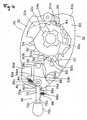
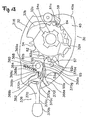
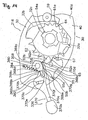
- the position holding and releasing mechanism 34 has, for example, eight positioning teeth 62 and seven feed teeth 64, and has the positioning body 54 which links to the winding body 32, and a positioning claw 56 which moves along a parallel surface with the plane 40a between an engaging position shown in Figure 4 where it engages with the positioning tooth 62 and a release position shown in Figure 5 where it does not engage with the positioning tooth 62.
- the position holding and releasing mechanism 34 has a rotation preventing claw 57 which moves along the parallel surface with the plane 40a between a contact position shown in Figure 5 where it engages with the positioning tooth 62 at a different position from the positioning claw 56, and a separation position shown in Figure 4 where it does not engage with the positioning tooth 62, a feed claw 59 which moves to a feed position shown by the two-dot chain line in Figure 4 where it engages with the feed tooth 64 and a release position shown by the solid line in Figure 4 where it separates therefrom, and a holding plate 61 (see Figure 3) which is mounted to the rotary shaft 46 to be incapable of rotating.
- the positioning body 54 has an engaging hole 54a which engages with the engaging projection 32c of the winding body 32, and moves integrally with the winding body 32.
- the positioning teeth 62 and the feed teeth 64 are provided in the number corresponding to the number of shift positions of the rear derailleur 18, and are formed at the outer peripheral surface of the positioning body 54 to project in the diameter direction.
- the positioning body 54 as well as the winding body 32 is biased in the cable releasing direction (counterclockwise in Figure 4) by the spring member 50.
- the spaces of the positioning teeth 62 and the feed teeth 64 are set based on the cable moving amount which is set in accordance with the shift position of the rear derailleur 18.
- the positioning claw 56 and the rotation preventing claw 57 are integrally formed at a swing body 55 which is swingably mounted to a swing shaft 65 vertically provided at the bracket 40.
- the swing body 55 is biased clockwise in Figure 4 by a spring member 58 such as a torsion coil spring so that the positioning claw 56 is disposed at the engaging position.
- An engaging projected portion 55a which projects in the diameter direction is formed at an outer peripheral surface of the swing body 55.
- An engaging pin 55b capable of contacting a pressing portion 68d which will be described later formed on a side surface of an action member 68 that will be described later is vertically provided downward at a tip end portion of the engaging projected portion 55a.
- the positioning claw 56 contacts a catching surface 62a of the positioning tooth 62 and inhibits rotation in the cable releasing direction of the positioning body 56 which is biased counterclockwise.
- the rotation preventing claw 57 moves to the contact position, it contacts a positioning tooth 62c which is in the cable releasing direction by one tooth from the positioning tooth 62b which the positioning claw 56 contacts, and prevents the positioning body 54 from continuously rotating without stopping in the cable releasing direction after the positioning claw 56 separates therefrom as shown in Figure 5.
- the positioning claw 56 is disposed at the position where it rides over the positioning tooth 62b with which it engages, as shown in Figure 5.
- the feed claw 59 is swingably mounted to a swing shaft 66 vertically provided at the second operation member 38 as shown in Figure 3.
- the feed claw 59 is biased clockwise in Figure 4 by a spring member 67 such as a torsion coil spring so that the feed claw 59 is disposed in the feed position.
- the holding plate 61 is mounted to the rotary shaft 46 to be incapable of rotating and fixed to an upper end of the swing shaft 65 by a snap ring 63, as shown in Figure 3.
- An abutting portion 61a for disposing the feed claw 59 at the release position side when the second operating member 38 is in the operation start position which will be described later is formed at the holding plate 61 to project toward the feed claw 59. Accordingly, the feed claw 59 is always disposed in the release position when the second operating member 38 is in the operation start position.
- the feed claw 59 is biased by the spring member 67 and swings toward the feed position.
- the first operating member 36 has the action member 68 which is mounted swingably around a swing shaft (one example of a first shaft) 80 vertically provided at the bracket 40, and the input member 70 which is mounted around a swing shaft (one example of a second shaft) vertically provided at the intermediate portion of the action member 68 to be spaced from the swing shaft 80.
- Both the swing shafts 80 and 82 are disposed to be substantially parallel with each other.
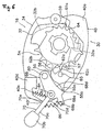
- the action member 68 causes the position holding and releasing mechanism 34 to act by the swing to the action position shown in Figure 5 from the neutral position shown in Figure 4 to move the winding body 32 in the cable releasing direction.
- the action member 68 is moved to the action position from the neutral position by the input member 70 to move the positioning claw 56 to the release position from the engaging position.
- the action member 68 has a first restricting portion (one example of a first abutting portion) 68a, a first spring hooking portion 68b and a second spring hooking portion 68c and the pressing portion 68d which engages with the engaging pin 55b on its side surface.
- the first restricting portion 68a is disposed between the swing shaft 80 and the first spring hooking portion 68b, and abuts on a second restricting portion (one example of a first abutting portion) 70d provided at a side surface of the input member 70.
- the first restricting portion 68a is provided to swing the input member 70 and the action member 68 integrally around the swing shaft 80 when the input member 70 is operated in a first direction to the lower side in Figure 4.
- the first spring hooking portion 68b is provided at a tip end of the action member 68 and one end of a second coil spring 86 is hooked at the first spring hooking portion 68b.
- the second coil spring 86 biases the input member 70 and the action member 68 in the direction to be close to each other.
- the second spring hooking portion 68c is disposed at the side surface at the opposite side from the first spring hooking portion 68b, and the other end of a first coil spring 84 is hooked at the second spring hooking portion 68c.
- the first coil spring 84 is provided to bias the action member 68 to the neutral position where it comes close to the wall portion 40d of the bracket 40.
- the pressing portion 68d is provided for rotating the swing body 55 via an engaging pin 55b counterclockwise linked to the swing of the action member 68 to the action position from the neutral position, and for moving the positioning claw 56 to the release position from the engaging position.
- the pressing portion 68d is constructed by an inclined surface which is inclined as curving smoothly.
- the input member 70 is a member that moves in the first direction shown in Figure 5 and in a second direction shown in Figure 6.
- the input member 70 has an arm member 70a which is swingably mounted to the swing shaft 82 vertically provided at the action member 68, and a knob portion 70b which is fixed to a tip end of the arm member 70a.
- a spring hooking portion 70c is formed at a position, which is opposed to the first spring hooking portion 68b, of an intermediate portion of the arm member 70a.
- the other end of the second coil spring 86 is hooked at the spring hooking portion 70c.
- the second restricting portion 70d is provided at a side surface between the spring hooking portion 70c and a base end portion.
- a fourth restricting portion (one example of a second abutting portion) 70e which abuts on a third restricting portion 40f of the wall portion 40d is provided at the side surface at the opposite side from the second restricting portion 70d.
- the second operating member 38 is mounted to the rotary shaft 46 swingably to the operation start position shown by the solid line and the operation finishing position shown by the dashed line in Figure 2.
- the second operating member 38 is biased to the operation start position by a spring member 75 such as a spiral spring.
- a knob portion 38a is provided at one end side of the second operating member 38.
- the swing shaft 66 which supports the feed claw 59 is vertically provided at the other end side with the swing center of the first operating member 38 therebetween.
- the front shift operating part 15 has the same structure in the mirror image relationship with the rear shift operating part 16, and is provided inside the rear brake lever 12.
- the action in the cable releasing direction is as follows.
- the positioning body 54 is biased to the cable releasing direction by the spring member 50, and therefore, the positioning body 54 rotates in the cable releasing direction.
- the rotation preventing claw 57 which is formed at the swing body 55 integrally with the positioning claw 56, moves to the contact position to stop the rotation of the swing body 55. Therefore, the positioning body 54 stops at the position where the positioning claw 56 rides over the positioning tooth 62b with which the positioning claw 56 engages.
- the action member 68 is returned to the neutral position by the first coil spring 84 as shown in Figure 7. Then, the input member 70 is also returned to the original position with the action member 68 by the second restricting portion 70d being pressed by the first restricting portion 68a as shown in Figure 7. Since at this time, in the swing body 55, the positioning claw 56 is biased to be positioned in the engaging position by the spring member 58, the swing body 55 swings clockwise, and the positioning claw 56 is disposed in the engaging position again. As a result, the positioning body 54 rotates in the cable releasing direction by the amount of one positioning tooth 62 and stops, and the winding body 32 also rotates in the cable releasing direction by the amount of one shift position.
- the positioning body 54 is biased in the cable releasing direction by the spring member 50, and therefore, the positioning body 54 rotates in the cable release direction.
- the rotation preventing claw 57 formed at the swing body 55 integrally with the positioning claw 56 moves to the contact position to stop the rotation of the swing body 55. Therefore, the positioning body 54 stops at the position where the positioning claw 56 rides over the positioning tooth 62b with which the positioning claw 56 engages.
- the action member 68 returns to the neutral position by the first coil spring 84.
- the fourth restricting portion 70e is in contact with the third restricting portion 40f, and therefore, the input member 70 also swings counterclockwise around the swing shaft 82 and returns to the original position as shown in Figure 7.
- the positioning claw 56 is biased to be disposed at the engaging position by the spring member 58 at this time, the swing body 55 swings clockwise, and the positioning claw 56 is disposed in the engaging position again.
- the positioning body 54 rotates in the cable releasing direction by the amount of one positioning tooth 62 and stops, and the winding body 32 also rotates in the cable releasing direction by the amount of one shift position.
- the action member 68 moves in the same direction to the action position from the neutral position even when the input member 70 is operated in either the first direction or the second direction. Therefore, the winding body 32 can be moved in the cable releasing direction by movement of the input member 70 in either direction of the first direction or the second direction, and the operating direction of the input member 70 can be adapted to rider's preference. Since the winding body 32 and the positioning claw 56 can be disposed in parallel, the shift operating part 16 can be compactly disposed.
- the action in the cable winding direction is as follows.
- the feed claw 59 is moved to the feed position by being biased by the spring member 67 and engages with the feed tooth 64, when the tip end passes the abutting portion 61a.
- the positioning body 54 rotates in the cable winding direction (clockwise in Figure 4) by the swing of the second operating member 38.
- the positioning claw 56 is in the engaging position until the positioning body 54 rotates, and in response to the swing of the second operating member 38, the positioning claw 56 is pressed by the adjacent positioning tooth 62c to the positioning tooth 62b by which it is positioned.
- the swing body 55 rotates counterclockwise, and the positioning claw 56 moves to the release position side.
- the engaging projected portion 55a rotates counterclockwise, and separates from the pressing portion 68d.
- the action member 68 is biased to the neutral position side by the first coil spring 84, the action member 68 and the input member 70 do not move.
- the positioning tooth 62c rides over the positioning claw 56, and the positioning claw 56 is moved to the engaging position with the positioning tooth 62c.
- the positioning body 54 rotates in the cable winding direction by the amount of one positioning tooth 62 and stops, and the winding body 32 also rotates in the cable winding direction by the amount of one shift position.
- the second operating member 38 is further swung toward the operation finishing position, the same action is repeated, and the winding body can be further rotated in the cable winding direction by the amount of one tooth.
- the first operating member which performs the cable releasing operation is constructed by the action member and the input member, but as shown in Figure 8, a second operating member 138 may be constructed by an action member 168 and an input member 170.
- the first operating member 36 is also constructed by the action member 68 and the input member 70 as in the above described embodiment, the first operating member 36 may be formed by one piece to perform cable releasing operation by the operation in one direction.
- the same member as in the first embodiment are assigned with the same reference numerals, and the members corresponding to those in the first embodiment are assigned with the reference numerals of the hundreds digits of the reference numerals in the first embodiment by changing them.
- the other construction and operation except for the second operating member 138 and the cover 144 are the same as those in the first embodiment, and therefore, the explanation thereof will be omitted.
- the second operating member 138 has the action member 168 which is mounted swingably around the rotary shaft (one example of the first shaft) 46 which penetrates through a cover 144 of the mounting part 30, and the input member 170 which is mounted around a swing shaft (one example of the second shaft) 182 which is vertically provided at an intermediate portion of the action member 168 to be spaced from the rotary shaft 46.
- a wall portion 144d having a spring hooking portion 144e at which one end of a first coil spring 184 is hooked is formed near the second operating member 138.
- a third restricting portion (one example of the second abutting portion) 144f which contacts a side surface of the input member 170 is formed at a tip end of the wall portion 144d.
- the rotary shaft 46 and the swing shaft 182 are disposed substantially parallel with each other.
- the feed claw 59 is swingably mounted to a tip end of the action member 168.
- the action member 168 causes the position holding and releasing mechanism 34 to act by swing to the clockwise action position from the neutral position shown in Figure 8 to move the winding body 32 in the cable winding direction.
- the action member 168 has a first restricting portion (one example of the first abutting portion) 168 which abuts on the input member 170, a first spring hooking portion 168b and a second spring hooking portion 168c on its side surface.
- the first restricting portion 168a is disposed between the rotary shaft 46 and the first spring hooking portion 168b, and abuts on a second restricting portion (one example of the first abutting portion) 170d which is provided on a side surface of the input member 170.
- the first restricting portion 168a is provided for integrally swinging the input member 170 and the action member 168 around the rotary shaft 46 when the input member 170 is operated in the first direction toward the upper side in Figure 8.
- the first spring hooking portion 168b is provided at a tip end of the action member 168, and one end of a second coil spring 186 is hooked at the first spring hooking portion 168b.
- the second coil spring 186 biases the input member 170 and the action member 168 in the direction to be close to each other.
- the second spring hooking portion 168c is disposed at the side surface at the opposite side from the first spring hooking portion 168b, and the other end of the first coil spring 184 is hooked at the second spring hooking portion 168c.
- the first coil spring 184 is provided to bias the action member 168 to the neutral position where it is close to the wall portion 144d of the cover 144.
- the input member 170 is a member which moves in the first direction (upper side) shown by the broken line in Figure 8 and the second direction (lower side).
- the input member 170 has an arm member 170a which is swingably mounted to the swing shaft 182 vertically provided at the action member 168, and a knob portion 170b fixed to a tip end of the arm member 170a, as shown in Figure 8.
- a spring hooking portion 170c is formed at the position, which is opposed to the first spring hooking portion 168b, of the intermediate portion of the arm member 170a.
- the other end of the second coil spring 186 is hooked at the spring hooking portion 170c.
- the second restricting portion 170d is provided at the side surface between the spring hooking portion 170c and a base end portion.
- a fourth restricting portion (one example of the second abutting portion) 170e which abuts on the third restricting portion 144f of the wall portion 144d is provided on the side surface at the opposite side from the second restricting
- the action in the cable winding direction is as follows.
- the action member 168 When the knob portion 170b of the input member 170 is operated in the first or the second direction, the action member 168 is swung to the action position from the neutral position clockwise around the rotary shaft 46 as in the above described embodiment and moves the feed claw 59 clockwise around the rotary shaft 46 in either case.
- the tip end of the feed claw 59 passes the abutting portion 61a, the feed claw 59 moves to the feed position by being biased by the spring member 67 and engages with the feed tooth 64.
- the positioning body 54 rotates in the cable winding direction (clockwise in Figure 4) by the swing of the action member 168.
- the positioning claw 56 is in the engaging position until the positioning body 54 rotates, but in response to the swing of the action member 168, the positioning claw 56 is pressed by the adjacent positioning tooth 62c to the positioning tooth 62b by which it is positioned. As a result, the swing body 55 rotates counterclockwise, and the positioning claw 56 moves to the release position side.
- the action member 168 is further swung in the direction of the operation finishing position by the input member 170, the positioning tooth 62c rides over the positioning claw 56, and the positioning claw 56 is moved to the engaging position with the positioning tooth 62c.
- the positioning body 54 rotates in the cable winding direction by the amount of one positioning tooth 62 and stops, and the winding body 32 also rotates in the cable winding direction by the amount of one shift position.
- the action member 168 is further swung toward the operation finishing position by the input member 170, the same action is repeated, and the winding body can be further rotated in the winding direction by the amount of one tooth.
- the cable winding operation may be made possible in both of the two directions.
- the second coil spring 86 is provided, but the second coil spring 86 may not be provided.
- the positions of the first restricting portion 68a and the second restricting portion 70d as the first abutting portion are not limited to those in the above described two embodiments.
- the other constructions than the first operating member are the same as those in the first embodiment, and therefore, the explanation of them will be omitted.
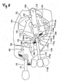
- the second coil spring is not provided as shown in Figure 9. Therefore, the spring hooking portions or the like, which accompany the second coil spring, are not provided. Further, the positions of a first restricting portion 268a and a second restricting portion 270d differ. The details of the constructions and action except for those of a first operating member 236 of a rear shift operating part 216 are the same as the first embodiment, and therefore, the explanation of them will be omitted.
- the first operating member 236 has an action member 268 mounted swingably around a swing shaft (one example of the first shaft) 280 which is vertically provided at the bracket 40, and an input member 270 mounted around a swing shaft (one example of the second shaft) 282 which is vertically provided at an intermediate portion of the action member 268 to be spaced from the swing shaft 280. Both the swing shafts 280 and 282 are disposed substantially parallel.
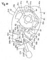
- the action member 268 causes the position holding and releasing mechanism 34 to act by swing to the action position shown in Figure 10 from the neutral position shown in Figure 9 to move the winding body 32 in the cable releasing direction.
- the action member 268 is moved to the action position from the neutral position by the input member 270 to move the positioning claw 56 to the release position from the engaging position.
- the action member 268 has the first restricting portion (one example of the first abutting portion) 268a which abuts on the input member 270, a second spring hooking portion 268c, and a pressing portion 268d which engages with the engaging pin 55b on its side surface.
- the first restricting portion 268a is, for example, a pin-shaped member which is vertically provided close to the swing shaft 282 between the swing shaft 280 and the swing shaft 282, and abuts on a second restricting portion (one example of the first abutting portion) 270d which is provided at the input member 270.
- This first restricting portion 268a is provided to swing the input member 270 and the action member 268 integrally around the swing shaft 280 when the input member 270 is operated in the first direction toward the lower side in Figure 9.
- the second spring hooking portion 268c is disposed at the side surface at the wall portion 40d side as in the first embodiment and the other end of the first coil spring 84 is hooked at the second spring hooking portion 68c.
- the first coil spring 84 is provided to bias the action member 68 toward the neutral position where it is close to the wall portion 40d of the bracket 40.
- the pressing portion 268d is provided to link to the swing of the action member 268 toward the action position from the neutral position to rotate the swing body 55 counterclockwise, and to move the positioning claw 56 to the release position from the engaging position.
- the pressing portion 268d is constructed by an inclined surface that is inclined while smoothly curving.
- the input member 270 is a member that moves in the first direction shown in Figure 10 and in the second direction shown in Figure 11.
- the input member 70 has an arm member 270a swingably mounted to the swing shaft 282 vertically provided at the action member 268, and a knob portion 270b which is fixed to a tip end of the arm member 270a as shown in Figure 9.
- a base end portion of the first arm portion 270a extends from the support portion of the swing shaft 282 in the direction to separate from the knob portion 270b, and the second restricting portion 270d is provided at a side surface of the extended portion, at the wall portion 40d side.
- the second restricting portion 270d contacts the first restricting portion 268a as described above.
- a fourth restricting portion (one example of the second abutting portion) 270e which abuts on the third restricting portion 40f of the wall portion 40d is provided on the side surface, at the wall portion 40d side, of the intermediate portion of the arm member 270a.
- the input member 270 and the action member 268 integrally swing counterclockwise around the swing shaft 280 toward the action position from the neutral position as shown in Figure 10. Then, the positioning claw 56 and the rotation preventing claw 57 act and the winding body 32 rotates in the cable releasing direction by the amount of one shift position as shown in Figure 12.
- the input member is mounted to the action member, but the mounting position of the input member is not limited to the above described three embodiments.
- an input member 370 of a rear shift operating portion 316 is movably mounted to the bracket 40 as shown in Figure 13.
- the other constructions except for the first operating member are the same as those in the first embodiment, and therefore, the explanation thereof will be omitted.
- the first operating member 336 has an action member 368 which is mounted swingably around a swing shaft (one example of the first shaft) 380 which is vertically provided at the bracket 40, and an input member 370 which is swingable around a swing shaft (one example of the third shaft) 382 which is vertically provided at the bracket 40 to be spaced from the swing shaft 380, as shown in Figure 13. Both swing shafts 380 and 382 are disposed substantially parallel.
- the action member 368 causes the position holding and releasing mechanism 34 to act by swing to the action position shown in Figure 14 from the neutral position shown in Figure 13 to move the winding body 32 in the cable releasing direction. Specifically, the action member 368 is moved to the action position from the neutral position by the input member 370 to move the positioning claw 56 to the release position from the engaging position.
- the action member 368 has a first to a third restricting portions (examples of the third to the fifth abutting portions) 368a to 368c which abut on the input member 370, a second spring hooking portion 368d, and a pressing portion 368e which engages with the engaging pin 55b on its side surface.
- the action member 368 has a circular main body portion 369a, and a first projected portion 369b which extends toward the input member 336 from the main body portion 369.
- the first restricting portion 368a is orthogonal to the straight line connecting the swing axes of a swing shaft 380 and a swing shaft 382, and is disposed at an outer peripheral surface of the main body portion 369a at a position where the straight line passing through the axis of the swing shaft 380 intersects the outer peripheral surface of the lower portion of the main body portion 369a.
- the first restricting portion 368a is disposed at the outer peripheral surface of the main body portion 369a separated from the swing shaft 382 from a lower side of the swing shaft 380.
- the second restricting portion 368b is provided at a side surface at the upper side in Figure 13 of the first projected portion 369b.
- the first and the second restricting portions 368a and 368b are provided to swing the input member 370 and the action member 368 integrally around the swing shaft 380 when the input member 370 is operated in the first direction toward the lower side in Figure 13. They are provided to make the input member 370 rest at the intermediate position when the action member 368 which is biased by a first coil spring 384 that will be described later is in the neutral position.
- the third restricting portion 368c is formed with a predetermined length on the top surface of the first projected portion 369b including the second restricting portion 368b. This length is longer than the length of contact of a sixth restricting portion (one example of a fifth abutting portion) that will be described later when the input member 370 moves in the second direction.
- the third restricting portion 368c is provided to swing the input member 370 around the swing shaft 382 with respect to the action member 368 and swing the action member 368 around the swing shaft 380 when the input member 370 is operated in the second direction toward the upper side in Figure 13.
- a second spring hooking portion 368d is provided at an edge portion of the main body portion 369a above the first projected portion 369b of the action member 368, and one end of the first coil spring 384 is hooked at the second spring hooking portion 368d. The other end of the first coil spring 384 is caught at the bracket 40. The first coil spring 384 biases the action member 368 toward the neutral position clockwise in Figure 13.
- the pressing portion 368e is provided to link to the swing of the action member 368 toward the action position from the neutral position to rotate the swing body 55 counterclockwise via the catching pin 55b and move the positioning claw 56 to the release position from the engaging position.
- the pressing portion 368e is the same as in the first embodiment, and is constructed by an inclined surface which inclines while smoothly curving.
- the input member 370 is a member that moves in the first direction shown in Figure 14 and in the second direction shown in Figure 15 from the intermediate position shown in Figure 13.
- the input member 370 has an arm member 370a which is mounted swingably around the swing shaft 382 which is vertically provided at the bracket 40, and a knob portion 370b which is fixed to a tip end of the arm member 370a, as shown in Figure 13.
- the arm member 370a is formed so that the intermediate portion is wider than the other portions.
- the arm member 370a has a long groove portion 370c in a circular arc shape at which the swing shaft 382 can be disposed at one end (lower end in Figure 13) when the action member 368 is disposed in the neutral position, at the wide intermediate potion.
- the long groove portion 370c is formed into the circular arc shape with the axis of the swing shaft 380 as a center.
- the long groove portion 370c is provided to prevent interference with the swing shaft 382 when the input member 370 swings in the first direction with the action member 368. It is also provided to restrict the swing range of the input member 370 in the first direction.
- the arm member 370a has a fourth and a fifth restricting portions (examples of the third and the fourth abutting portions) 370d and 370e which contact the action member 368 when the input member 370 moves in the first direction, and a sixth restricting portion (one example of the fifth abutting portion) 370f which contacts the action member 368 when the input member 370 swings in the second direction.
- the fourth restricting portion 370d is formed on an upper side surface of the tip end of a second projected portion 370g which extends to the lower side of the first projected portion 369b of the action member 368 to be contactable to the first restricting portion 368a.
- the second projected portion 370g extends to the right side in Figure 13 from a lower side of the swing axis of the swing shaft 380 on the outer peripheral surface of the main body portion 369a of the action member 368.
- the fifth restricting portion 370e is disposed at the lower side surface of a third projected portion 370h which is disposed to sandwich the action member 368 with the second projected portion 370g to be contactable to the second restricting portion 368b.
- the third projected portion 370h extends to the position where it does not contact the outer peripheral surface of the main body portion 369a of the action member 368.
- the fourth and the fifth restricting portions 370d and 370e are formed to contact the first and the second restricting portions 368a and 368b of the action member 368 when the action member 368 is in the neutral position and the input member 370 is in the intermediate position, and when the input member 370 swings in the first direction.
- the first and the fourth restricting portions 368a and 370d are disposed to separate from the swing shaft 382 from the lower side of the swing axis of the swing shaft 380 as described above, the action member 368 does not rotate clockwise even when the fourth restricting portion 370d contacts the first restricting portion 368a. Since the fifth restricting portion 370e contacts the second restricting portion 368b and the fourth contact portion 370e contacts the first contact portion 368a, the input member 370 is biased by the first coil spring 384 via the action member 368 so that the swing shaft 382 is disposed at the lower end portion of the long groove portion 370c.
- the sixth restricting portion 370f is formed at the tip end of the third projected portion 370h to be projected in the circular arc shape, and includes the fifth restricting portion 370e.
- the sixth restricting portion 370f is provided to move in contact with the third restricting portion 368c to swing the input member 370 clockwise around the swing shaft 382 and to swing the action member 368 counterclockwise around the swing shaft 380.
- the action in the cable releasing direction is as follows.
- the fourth restricting portion 370d of the input member 370 contacts the first restricting portion 368a, while the fifth restricting portion 370e contacts the second restricting portion 368b, and the action member 368 is pressed by the fifth restricting portion 370e.
- the action member 368 is pressed by the fifth restricting portion 370e, the input member 370 and the action member 368 can integrally swing around the swing shaft 380 counterclockwise in Figure 14 toward the action position from the neutral position even if the swing shaft 382 is disposed in the long groove portion 270c, because the long groove portion 370c is formed by the circular arc with the swing shaft 380 as the center.
- the swing body 55 swings counterclockwise in Figure 13 from the state in which the positioning claw 56 is in the engaging position shown in Figure 13, and the positioning claw 56 moves to the release position shown in Figure 14 from the engaging position to separate from the positioning body 54.
- the positioning body 54 is biased in the cable releasing direction by the spring member 50, and therefore, the positioning body 54 rotates in the cable releasing direction.
- the rotation preventing claw 57 which is formed at the swing body 55 integrally with the positioning claw 56, moves to the contact position and stops rotation of the swing body 55. Therefore, the positioning body 54 stops at the position where the positioning claw 56 rides over the positioning tooth 62b with which the positioning claw 56 is engaged.
- the action member 368 returns to the neutral position by the first coil spring 384 as shown in Figure 16. Then, the fifth restricting portion 370e is pressed by the second restricting portion 368b and the input member 370 also returns to the original intermediate position with the action member 368 as shown in Figure 16. Since the swing body 55 is biased by the spring member 58 so that the positioning claw 56 is disposed in the engaging position at this time, the swing body 55 swings clockwise, and the positioning claw 56 is disposed in the engaging position again. As a result, the positioning body 54 rotates in the cable releasing direction by the amount of one positioning tooth 62 and stops, and the winding body 32 rotates in the cable releasing direction by the amount of one shift position.
- the sixth restricting portion 370f of the input member 370 contacts the third restricting portion 368c, and the input member 370 swings clockwise around the swing shaft 382 since the input member 370 is biased by the first coil spring 384 via the action member 368 so that the swing shaft 382 is disposed at the lower end portion of the long groove portion 370c.
- the fourth contact portion 370d separates from the first contact portion 368a.
- the action member 368 swings counterclockwise in Figure 13 around the swing shaft 380 as at the time of operation in the first direction.
- the swing body 55 swings counterclockwise from the state where the positioning claw 56 is in the engaging position shown in Figure 13, and the positioning claw 56 moves to the release position shown in Figure 15 from the engaging position and separates from the positioning body 54.
- the positioning body 54 is biased in the cable releasing direction by the spring member 50, and therefore, the positioning body 54 rotates in the cable releasing direction.
- the rotation preventing claw 57 which is formed at the swing body 55 integrally with the positioning claw 56 moves to the contact position, and stops rotation of the swing body 55. Therefore, the positioning body 54 stops at the position where the positioning claw 56 rides over the positioning tooth 62b with which the positioning claw 56 is engaged.
- the action member 368 returns to the neutral position by the first coil spring 384. Then, the input member 370 swings counterclockwise around the swing shaft 382 and also returns to the original position as shown in Figure 16, since the sixth restricting portion 370f contacts the third restricting portion 368c. Since the swing body 55 is biased by the spring member 58 so that the positioning claw 56 is disposed in the engaging position at this time, the swing body 55 swings clockwise, and the positioning claw 56 is disposed in the engaging position again. As a result, the positioning body 54 rotates in the cable releasing direction by the amount of one positioning tooth 62 and stops, and the winding body 32 also rotates in the cable releasing direction by the amount of one shift position.
- the action member 368 moves in the same direction to the action position from the neutral position when the input member 370 is operated either in the first or the second direction. Therefore, the winding body 32 can be moved in the cable releasing direction by movement of the input member 370 both in the first direction and the second direction, and the operating direction of the input member 370 can be adapted to rider's preference.
- the winding body 32 and the positioning claw 56 are disposed parallel, and therefore, the shift operating part 16 can be disposed compactly.
- the first contact portion 368a is formed to project outward in the diameter direction from the main body portion 369a to contact the tip end of the fourth restricting portion 370d.
Landscapes
- Engineering & Computer Science (AREA)
- Mechanical Engineering (AREA)
- Chemical & Material Sciences (AREA)
- Combustion & Propulsion (AREA)
- Transportation (AREA)
- Steering Devices For Bicycles And Motorcycles (AREA)
- Mechanical Control Devices (AREA)
- Gear-Shifting Mechanisms (AREA)
Abstract
Description
- The present invention relates to an operating device, and particularly relates to a bicycle shift operating device which is mounted to a bicycle.
- There are bicycles equipped with transmissions such as internal transmissions and external transmissions. To perform shift operations of these transmissions, shift operating devices connected to the transmissions via shift cables are used. As the conventional shift operating devices, lever type transmission having winding levers (one example of an input member) and release levers (one example of the input member) are known. In the lever type shift operating devices, the art of swingly operating the winding lever and the release lever in the same direction (for example, see Patent Document 1) and the art of swingly operating them in the different directions (for example, see Patent Document 2) are known. When the winding lever and the release lever are operated in the pressing direction by a thumb in the former prior art, the shift cable is wound up or released to be able to shift. When the winding lever is operated in the pressing direction by a thumb in the latter prior art, the shift cable is pulled in the winding direction by one step to shift, and when it is operated in the direction pulling to the front side by a forefinger, the shift cable is returned in the releasing direction to shift.
- [Patent Document 1] Specification of
Japanese Patent No. 2730555 - [Patent Document 2] Specification of
Japanese Patent No. 3065656 - In both of the above described prior arts, the operating direction of the winding levers is the pressing direction by thumbs. As for the release levers, the operating direction is the same direction as that of the winding lever in the former art, and the operating direction is the different direction from that of the winding lever in the latter art. The operating directions of the input members such as the winding lever and the release lever are sometimes desired to be changed in accordance with rider's preference. In the above described prior arts, however, the operating directions of the input members in both cases are limited to the fixed directions, and cannot be adapted to the rider's preference.
- An object of the present invention is to make it possible to adapt the operating direction of the input member to rider's preference in the bicycle shift operating device having levers.
- A bicycle shift operating device according to invention 1 includes a mounting part mountable to the bicycle, a cable catching body, a position holding mechanism, an action member, and an input member. The cable catching body is mounted to the mounting part movably in a cable pulling direction and a cable releasing direction. The position holding mechanism selectively holds the cable catching body in any one of a plurality of holding positions. The action member is a member mounted to the mounting part swingably around a first shaft, and causes the position holding mechanism to act by swing to an action position from a neutral position to move the cable catching body in either one of the cable pulling direction or the cable releasing direction. The input member is a member that is mounted to the action member and moves the action member to the action position from the neutral position by moving in a first direction and a second direction.
- When the input member is moved in the first direction or the second direction in this shift operating device, the action member moves to the operating position from the neutral position in either case. When the action member moves to the action position from the neutral position, the position holding mechanism is caused to act, and the cable catching body is moved in either one of the cable pulling direction or the cable releasing direction. As a result, the shift cable moves in the cable pulling direction or in the cable releasing direction to perform a shift operation. In this case, the action member moves to the action position from the neutral position to be able to move the cable catching body in the cable pulling direction or in the cable releasing direction by the movement of the input member in both the first direction and the second direction, and therefore, the operating direction of the input member can be adapted to rider's preference.
- In the bicycle shift operating device according to
invention 2, in the device as set forth in the invention 1, the input member is movably mounted to the action member. In this case, the input member and the action member can be integrally moved and separately moved, and therefore, the action member is moved to the action position from the neutral position with the respective actions of the input member, whereby the operating direction of the input member can be easily adapted to rider's preference. - In the bicycle shift operating device according to invention 3, in the device as set forth in the
invention 2, the input member is mounted to the action member swingably around a second shaft spaced from the first shaft. In this case, the input member and the action member both swing, and therefore, the input member and the action member are supported by the shaft. Therefore, the support structure of the input member and the action member is simplified. - In the bicycle shift operating device according to invention 4, in the device as set forth in the
invention 2 or 3, the input member and the action member respectively have first abutting portions which contact each other when the input member moves in the first direction, and integrally swing around the first shaft when the input member moves in the first direction. When the input member moves in the first direction in this case, the action member and the input member contact each other at their first abutting portions, and the action member swings around the first shaft integrally with the input member to move to the shift position from the neutral position. Here, the input member and the action member are brought into contact with each other at the first abutting portions to move both of them integrally, and therefore, the action member can be easily moved to the action position when the input member is moved in the first direction. - In the bicycle shift operating device according to
invention 5, in the device as set forth in any one of theinventions 2 to 4, the input member and the mounting part respectively have second abutting portions which contact each other when the input member moves in the second direction, and the input member swings around the second shaft and the action member swings around the first shaft, when the input member moves in the second direction. In this case, when the input member swings in the second direction, the input member swings around the second shaft by the contact of the second abutting portions and the mounting portion of the input member moves in the reverse direction. Thereby, the action member swings around the first shaft toward the action position. Here, the mounting part and the input member are brought into contact with each other at the second abutting portions to swing the action member around the first shaft, and therefore, when the input member is moved in the second direction, the action member can be easily moved to the action position. - In the bicycle shift operating device according to invention 6, in the device as set forth in the
invention 5, the first and second abutting portions are in contact with each other when the action member is in the neutral position. In this case, the input member contacts all the abutting portions, and therefore, even if the input member is moved in either direction of the first or the second direction, the action member can be quickly moved toward the action position. - In the bicycle shift operating device according to invention 7, in the device as set forth in any one of the
inventions 2 to 6, a first biasing member, which has one end caught at the mounting part and the other end caught at the action member, and biases the action member in a direction of the neutral position from the action position, is further included. In this case, the action member is biased toward the neutral position, and therefore, when the operation by the input member is finished, the action member returns to the neutral position. Therefore, in the shift operation, the action member always acts from the neutral position, and there is no need to return the action member to the neutral position. - In the bicycle shift operating device according to invention 8, in the device as set forth in the invention 7, a second biasing member, which has one end caught at the action member and the other end caught at the input member, and biases the action member and the input member in a direction to bring them close to each other, is further included. In this case, when the operation by the input member is finished, the action member and the input member come close to each other, and therefore, the positional relationship of the input member and the action member can be always kept constant.
- In the bicycle shift operating device according to invention 9, in the device as set forth in the invention 1, the input member is movably mounted to the mounting part. In this case, the action member and the input member are separately movable, and therefore, both of them are linked so that the action member moves to the action position from the neutral position with respect to the operation of the input member in both directions, whereby the operating direction of the input member can be easily adapted to rider's preference.
- In the bicycle shift operating device according to invention 10, in the device as set forth in the invention 9, the input member is mounted to the mounting part swingably around a third shaft which is spaced from the first shaft. In this case, the input member and the action member swing together, and therefore, the input member and the action member only have to be supported by the shaft. Therefore, the support structure of the input member and the action member is simplified.
- In the bicycle shift operating device according to
invention 11, in the device as set forth in the invention 9 or 10, the input member and the action member respectively have third and fourth abutting portions which contact each other when the input member moves in the first direction, and integrally swing around the first shaft when the input member moves in the first direction. In this case, when the input member moves in the first direction, the third and the fourth abutting portions of the action member and the input member contact each other, and the action member swings around the first shaft integrally with the input member to move to the action position from the neutral position. Here, both of the input member and the action member are moved by being brought into contact with each other at the third and the fourth abutting portions, and therefore, when the input member is moved in the first direction, the action member can be easily moved to the action position. - In the bicycle shift operating device according to
invention 12, in the device as set forth in any one of the inventions 9 to 11, the input member and the action member respectively have fifth abutting portions which contact each other when the input member moves in the second direction, the input member swings around the third shaft, and the action member swings around the first shaft, when the input member moves in the second direction. When the input member swings in the second direction in this case, the input member swings around the third shaft by the contact of the fifth abutting portions, and the action member swings around the first shaft toward the action position. Here, the action member is swung around the first shaft by contacting the input member and the action member at the fifth abutting portions, and therefore, when the input member is moved in the second direction, the action member can be easily moved to the action position. - In the bicycle shift operating device according to invention 13, in the device as set forth in any one of the inventions 9 to 12, a third biasing member that has one end caught at the mounting part and the other end caught at the action member, and biases the action member in a direction of the neutral position from the action position is further included. In this case, the action member can be easily returned to the neutral position by only taking a hand off the input member.
- The bicycle shift operating device according to invention 14, in the device as set forth in any one of the inventions 10 to 13, the input member has a long groove portion in a circular arc shape with the first shaft as a center and the third shaft capable of being disposed at one end when the action member is disposed in the neutral position. In this case, even if the third shaft is provided, the input member can be moved in the first direction around the first shaft.
- In the bicycle shift operating device according to
invention 15, in the device as set forth in any one of the inventions 1 to 14, the position holding mechanism has a positioning body movable integrally with the cable catching body and having a plurality of positioning teeth, and a positioning member that engages with the positioning tooth and holds the cable catching body in any one of the plurality of holding positions. In this case, the cable catching body can be reliably held in the holding position by the positioning tooth and the positioning member. - In the bicycle shift operating device according to
invention 16, in the device as set forth in theinvention 15, the positioning member is mounted to the mounting part movably between an engaging position where it engages with the positioning tooth and a release position where it does not engage with the above described positioning tooth, and is moved to the release position from the engaging position by swing of the action member to the action position from the neutral position. In this case, the position holding of the positioning body can be released in either case of the operations in both directions of the input member. - According to the present invention, the action member moves to the action position from the neutral position to move the cable catching body in the cable pulling direction or in the cable releasing direction by the movement of the input member in both of the first direction and the second direction, and therefore, the operating direction of the input member can be adapted to rider's preference.
- In Figure 1, a bicycle 1 equipped with a first embodiment of the present invention includes a
frame 2 having a suspension fork 3, and a handlebar 4 fixed to an upper portion of the suspension fork 3. Afront derailleur 17 constructing an external transmission is mounted to an intermediate portion of theframe 2, and arear derailleur 18 is mounted to a rear end portion of theframe 2. Thefront derailleur 17 is disposed at a lower portion of aseat tube 2b of theframe 2, for example, and guides a chain 23 to any of sprockets of afront chain wheel 19a having, for example, three sprockets. Therear derailleur 18 is disposed at a rear end portion of a chain stay 2c of theframe 2, and guides the chain 23 to any of sprockets of arear chain wheel 19b having, for example, eight sprockets. Thefront derailleur 17 and therear derailleur 18 are connected to front and rear shift operating parts (one example of a shift operating device) 15 and 16 via a front and arear shift cables - The front and rear
shift operating parts shift operating part 15 and the rearshift operating part 16 are in the mirror image relationship, and have substantially the same construction and perform substantially the same action except for the number of shift steps, and therefore, only the rearshift operating part 16 will be described in the explanation of the construction and action hereunder. - The rear
shift operating part 16 has a mountingpart 30 mountable to the handlebar 4 inside thefront brake lever 11 as shown in Figure 2. In Figure 2, the rearshift operating part 16 is seen from the lower side. The mountingpart 30 may be integrally fixed to a bracket of thefront brake lever 11. - As shown in Figure 3, the rear
shift operating part 16 has a winding body (one example of a cable catching body) 32 which is mounted to the mountingpart 30 movably in a cable pulling direction and a cable releasing direction of ashift cable 26, a position holding and releasing mechanism (one example of a position holding mechanism) 34 which selectively holds the windingbody 32 in any one of a plurality of holding positions corresponding to a plurality of shift positions of therear derailleur 18, afirst operating member 36 having anaction member 68 and aninput member 70 to perform a cable releasing operation, and asecond operating member 38 for performing a cable winding (pulling) operation. The rearshift operating part 16 also has a first coil spring (one example of a first biasing member) 84 disposed between theaction member 68 and the mountingpart 30 and a second coil spring (one example of a second biasing member) 86 which is disposed between theaction member 68 and theinput member 70. - As shown in Figures 3 and 4, the mounting
part 30 has abracket 40 of a metal plate, for example, mountable to the handlebar 4 with a fastening bolt, acover 42 which is attached to thebracket 40, and acover 44 which is attached to thebracket 40 to be spaced from thecover 42. Thebracket 40 has aplane 40a on which the windingbody 32 is disposed, and anopening 40b to which arotary shaft 46 is mounted to be incapable of rotating. Therotary shaft 46 penetrates through theopening 40b to extend upward. A tip end of therotary shaft 46 is fixed by a fixingbolt 41, and fixes thesecond operating member 38. Afemale screw portion 40c in which an outer catchingpart 27 for catching anouter casing 26b (Figure 1) of therear shift cable 26 is screwed is formed in thebracket 40. Awall portion 40d having aspring hooking portion 40e at which one end of thefirst coil spring 84 is hooked is formed near thefirst operating member 36. A third restricting portion (one example of a second abutting portion) 40f which contacts a side surface of theinput member 70 is formed at a tip end of thewall portion 40d. - The winding
body 32 is movable along a plane parallel with theplane 40a of thebracket 40. Specifically, the windingbody 32 is mounted to therotary shaft 46 via abush 52 to be movable (rotatable) in the cable winding (pulling) direction and cable releasing direction. The windingbody 32 has aninner catching portion 32a which catches a cable nipple fixed to a tip end of aninner cable 26a (Figure 1) of therear shift cable 26 and acable winding groove 32b for winding up theinner cable 26a, on its outer peripheral surface. The windingbody 32 is biased in the cable releasing direction (counterclockwise in Figure 4) by aspring member 50 such as a torsion coil spring. Thespring member 50 has one end caught at the windingbody 32 and the other end caught at thebracket 40 which will be described later. An engagingprojection 32c for linking to and rotating apositioning body 54 which will be described later of the position holding and releasingmechanism 34 is formed on a top surface of the windingbody 32. - The position holding and releasing
mechanism 34 has, for example, eight positioningteeth 62 and sevenfeed teeth 64, and has thepositioning body 54 which links to the windingbody 32, and apositioning claw 56 which moves along a parallel surface with theplane 40a between an engaging position shown in Figure 4 where it engages with thepositioning tooth 62 and a release position shown in Figure 5 where it does not engage with thepositioning tooth 62. Also, the position holding and releasingmechanism 34 has arotation preventing claw 57 which moves along the parallel surface with theplane 40a between a contact position shown in Figure 5 where it engages with thepositioning tooth 62 at a different position from thepositioning claw 56, and a separation position shown in Figure 4 where it does not engage with thepositioning tooth 62, afeed claw 59 which moves to a feed position shown by the two-dot chain line in Figure 4 where it engages with thefeed tooth 64 and a release position shown by the solid line in Figure 4 where it separates therefrom, and a holding plate 61 (see Figure 3) which is mounted to therotary shaft 46 to be incapable of rotating. - The
positioning body 54 has anengaging hole 54a which engages with the engagingprojection 32c of the windingbody 32, and moves integrally with the windingbody 32. The positioningteeth 62 and thefeed teeth 64 are provided in the number corresponding to the number of shift positions of therear derailleur 18, and are formed at the outer peripheral surface of thepositioning body 54 to project in the diameter direction. Thepositioning body 54 as well as the windingbody 32 is biased in the cable releasing direction (counterclockwise in Figure 4) by thespring member 50. The spaces of the positioningteeth 62 and thefeed teeth 64 are set based on the cable moving amount which is set in accordance with the shift position of therear derailleur 18. - The
positioning claw 56 and therotation preventing claw 57 are integrally formed at aswing body 55 which is swingably mounted to aswing shaft 65 vertically provided at thebracket 40. Theswing body 55 is biased clockwise in Figure 4 by aspring member 58 such as a torsion coil spring so that thepositioning claw 56 is disposed at the engaging position. An engaging projectedportion 55a which projects in the diameter direction is formed at an outer peripheral surface of theswing body 55. Anengaging pin 55b capable of contacting apressing portion 68d which will be described later formed on a side surface of anaction member 68 that will be described later is vertically provided downward at a tip end portion of the engaging projectedportion 55a. - The
positioning claw 56 contacts a catchingsurface 62a of thepositioning tooth 62 and inhibits rotation in the cable releasing direction of thepositioning body 56 which is biased counterclockwise. When therotation preventing claw 57 moves to the contact position, it contacts apositioning tooth 62c which is in the cable releasing direction by one tooth from thepositioning tooth 62b which thepositioning claw 56 contacts, and prevents thepositioning body 54 from continuously rotating without stopping in the cable releasing direction after thepositioning claw 56 separates therefrom as shown in Figure 5. When therotation preventing claw 57 is in the contact position, thepositioning claw 56 is disposed at the position where it rides over thepositioning tooth 62b with which it engages, as shown in Figure 5. - The
feed claw 59 is swingably mounted to aswing shaft 66 vertically provided at thesecond operation member 38 as shown in Figure 3. Thefeed claw 59 is biased clockwise in Figure 4 by aspring member 67 such as a torsion coil spring so that thefeed claw 59 is disposed in the feed position. - The holding
plate 61 is mounted to therotary shaft 46 to be incapable of rotating and fixed to an upper end of theswing shaft 65 by asnap ring 63, as shown in Figure 3. Anabutting portion 61a for disposing thefeed claw 59 at the release position side when thesecond operating member 38 is in the operation start position which will be described later is formed at the holdingplate 61 to project toward thefeed claw 59. Accordingly, thefeed claw 59 is always disposed in the release position when thesecond operating member 38 is in the operation start position. When thesecond operating member 38 is operated toward the operation finishing position from the operation start position and the tip end of thefeed claw 59 passes the abuttingportion 61a, thefeed claw 59 is biased by thespring member 67 and swings toward the feed position. - As shown in Figures 3 and 4, the
first operating member 36 has theaction member 68 which is mounted swingably around a swing shaft (one example of a first shaft) 80 vertically provided at thebracket 40, and theinput member 70 which is mounted around a swing shaft (one example of a second shaft) vertically provided at the intermediate portion of theaction member 68 to be spaced from theswing shaft 80. Both theswing shafts action member 68 causes the position holding and releasingmechanism 34 to act by the swing to the action position shown in Figure 5 from the neutral position shown in Figure 4 to move the windingbody 32 in the cable releasing direction. Specifically, theaction member 68 is moved to the action position from the neutral position by theinput member 70 to move thepositioning claw 56 to the release position from the engaging position. Theaction member 68 has a first restricting portion (one example of a first abutting portion) 68a, a firstspring hooking portion 68b and a secondspring hooking portion 68c and thepressing portion 68d which engages with theengaging pin 55b on its side surface. - The first restricting
portion 68a is disposed between theswing shaft 80 and the firstspring hooking portion 68b, and abuts on a second restricting portion (one example of a first abutting portion) 70d provided at a side surface of theinput member 70. The first restrictingportion 68a is provided to swing theinput member 70 and theaction member 68 integrally around theswing shaft 80 when theinput member 70 is operated in a first direction to the lower side in Figure 4. The firstspring hooking portion 68b is provided at a tip end of theaction member 68 and one end of asecond coil spring 86 is hooked at the firstspring hooking portion 68b. Thesecond coil spring 86 biases theinput member 70 and theaction member 68 in the direction to be close to each other. The secondspring hooking portion 68c is disposed at the side surface at the opposite side from the firstspring hooking portion 68b, and the other end of afirst coil spring 84 is hooked at the secondspring hooking portion 68c. Thefirst coil spring 84 is provided to bias theaction member 68 to the neutral position where it comes close to thewall portion 40d of thebracket 40. Thepressing portion 68d is provided for rotating theswing body 55 via anengaging pin 55b counterclockwise linked to the swing of theaction member 68 to the action position from the neutral position, and for moving thepositioning claw 56 to the release position from the engaging position. Thepressing portion 68d is constructed by an inclined surface which is inclined as curving smoothly. - The
input member 70 is a member that moves in the first direction shown in Figure 5 and in a second direction shown in Figure 6. Theinput member 70 has anarm member 70a which is swingably mounted to theswing shaft 82 vertically provided at theaction member 68, and aknob portion 70b which is fixed to a tip end of thearm member 70a. Aspring hooking portion 70c is formed at a position, which is opposed to the firstspring hooking portion 68b, of an intermediate portion of thearm member 70a. The other end of thesecond coil spring 86 is hooked at thespring hooking portion 70c. The second restrictingportion 70d is provided at a side surface between thespring hooking portion 70c and a base end portion. A fourth restricting portion (one example of a second abutting portion) 70e which abuts on a third restrictingportion 40f of thewall portion 40d is provided at the side surface at the opposite side from the second restrictingportion 70d. - The
second operating member 38 is mounted to therotary shaft 46 swingably to the operation start position shown by the solid line and the operation finishing position shown by the dashed line in Figure 2. Thesecond operating member 38 is biased to the operation start position by aspring member 75 such as a spiral spring. Aknob portion 38a is provided at one end side of thesecond operating member 38. Theswing shaft 66 which supports thefeed claw 59 is vertically provided at the other end side with the swing center of thefirst operating member 38 therebetween. - The front
shift operating part 15 has the same structure in the mirror image relationship with the rearshift operating part 16, and is provided inside therear brake lever 12. - Next, a shift action of the rear
shift operating part 16 will be described. - The action in the cable releasing direction is as follows.
- As shown in Figures 4 and 5, when the
knob portion 70b of theinput member 70 of thefirst operating member 36 is operated in the first direction, the second restrictingportion 70d of theinput member 70 contacts the first restrictingportion 68a to press theaction member 68, and theinput member 70 and theaction member 68 integrally swing around theswing shaft 80 to the action position from the neutral position counterclockwise in Figure 4. When theaction member 68 swings to the action position, theswing body 55 swings counterclockwise in Figure 4 from a state in which thepositioning claw 56 is in the engaging position shown in Figure 4, and thepositioning claw 56 moves to the release position shown in Figure 5 from the engaging position and separates from thepositioning body 54. As a result, thepositioning body 54 is biased to the cable releasing direction by thespring member 50, and therefore, thepositioning body 54 rotates in the cable releasing direction. However, when the positioning claw moves to the release position, therotation preventing claw 57, which is formed at theswing body 55 integrally with thepositioning claw 56, moves to the contact position to stop the rotation of theswing body 55. Therefore, thepositioning body 54 stops at the position where thepositioning claw 56 rides over thepositioning tooth 62b with which thepositioning claw 56 engages. - When the operation is stopped and a hand is taken off the
knob portion 70b in this state, theaction member 68 is returned to the neutral position by thefirst coil spring 84 as shown in Figure 7. Then, theinput member 70 is also returned to the original position with theaction member 68 by the second restrictingportion 70d being pressed by the first restrictingportion 68a as shown in Figure 7. Since at this time, in theswing body 55, thepositioning claw 56 is biased to be positioned in the engaging position by thespring member 58, theswing body 55 swings clockwise, and thepositioning claw 56 is disposed in the engaging position again. As a result, thepositioning body 54 rotates in the cable releasing direction by the amount of onepositioning tooth 62 and stops, and the windingbody 32 also rotates in the cable releasing direction by the amount of one shift position. - Meanwhile, when the
knob portion 70b of theinput member 70 of thefirst operating member 36 is operated in the second direction as shown in Figures 4 and 6, the fourth restrictingportion 70e of theinput member 70 contacts the third restrictingportion 40f and theinput member 70 swings clockwise around theswing shaft 82. Thereby, theaction member 68 swings counterclockwise in Figure 4 around theswing shaft 80 as at the time of the operation in the first direction. When theaction member 68 swings to the action position, theswing body 55 swings counterclockwise in Figure 4 from the state in which thepositioning claw 56 is in the engaging position shown in Figure 4, and thepositioning claw 56 moves to the release position shown in Figure 6 from the engaging position and separates from thepositioning body 54. As a result, thepositioning body 54 is biased in the cable releasing direction by thespring member 50, and therefore, thepositioning body 54 rotates in the cable release direction. However, when the positioning claw moves to the release position, therotation preventing claw 57 formed at theswing body 55 integrally with thepositioning claw 56 moves to the contact position to stop the rotation of theswing body 55. Therefore, thepositioning body 54 stops at the position where thepositioning claw 56 rides over thepositioning tooth 62b with which thepositioning claw 56 engages. - When the operation is stopped and the hand is taken off the
knob portion 70b in this state, theaction member 68 returns to the neutral position by thefirst coil spring 84. Then, the fourth restrictingportion 70e is in contact with the third restrictingportion 40f, and therefore, theinput member 70 also swings counterclockwise around theswing shaft 82 and returns to the original position as shown in Figure 7. Since in theswing body 55, thepositioning claw 56 is biased to be disposed at the engaging position by thespring member 58 at this time, theswing body 55 swings clockwise, and thepositioning claw 56 is disposed in the engaging position again. As a result, thepositioning body 54 rotates in the cable releasing direction by the amount of onepositioning tooth 62 and stops, and the windingbody 32 also rotates in the cable releasing direction by the amount of one shift position. - Here, the
action member 68 moves in the same direction to the action position from the neutral position even when theinput member 70 is operated in either the first direction or the second direction. Therefore, the windingbody 32 can be moved in the cable releasing direction by movement of theinput member 70 in either direction of the first direction or the second direction, and the operating direction of theinput member 70 can be adapted to rider's preference. Since the windingbody 32 and thepositioning claw 56 can be disposed in parallel, theshift operating part 16 can be compactly disposed. - The action in the cable winding direction is as follows.
- When the
second operating member 38 is operated in the direction of the operation finishing position from the operation start position, thefeed claw 59 is moved to the feed position by being biased by thespring member 67 and engages with thefeed tooth 64, when the tip end passes the abuttingportion 61a. As a result, thepositioning body 54 rotates in the cable winding direction (clockwise in Figure 4) by the swing of thesecond operating member 38. Thepositioning claw 56 is in the engaging position until thepositioning body 54 rotates, and in response to the swing of thesecond operating member 38, thepositioning claw 56 is pressed by theadjacent positioning tooth 62c to thepositioning tooth 62b by which it is positioned. As a result, theswing body 55 rotates counterclockwise, and thepositioning claw 56 moves to the release position side. At this time, the engaging projectedportion 55a rotates counterclockwise, and separates from thepressing portion 68d. In addition, since theaction member 68 is biased to the neutral position side by thefirst coil spring 84, theaction member 68 and theinput member 70 do not move. When thesecond operating member 38 is further swung in the direction of the operation finishing position, thepositioning tooth 62c rides over thepositioning claw 56, and thepositioning claw 56 is moved to the engaging position with thepositioning tooth 62c. As a result, thepositioning body 54 rotates in the cable winding direction by the amount of onepositioning tooth 62 and stops, and the windingbody 32 also rotates in the cable winding direction by the amount of one shift position. When thesecond operating member 38 is further swung toward the operation finishing position, the same action is repeated, and the winding body can be further rotated in the cable winding direction by the amount of one tooth. - In the first embodiment, the first operating member which performs the cable releasing operation is constructed by the action member and the input member, but as shown in Figure 8, a
second operating member 138 may be constructed by anaction member 168 and aninput member 170. Though in Figure 8, thefirst operating member 36 is also constructed by theaction member 68 and theinput member 70 as in the above described embodiment, thefirst operating member 36 may be formed by one piece to perform cable releasing operation by the operation in one direction. In the explanation hereunder, the same member as in the first embodiment are assigned with the same reference numerals, and the members corresponding to those in the first embodiment are assigned with the reference numerals of the hundreds digits of the reference numerals in the first embodiment by changing them. In the second embodiment, the other construction and operation except for thesecond operating member 138 and thecover 144 are the same as those in the first embodiment, and therefore, the explanation thereof will be omitted. - In Figure 8, the
second operating member 138 has theaction member 168 which is mounted swingably around the rotary shaft (one example of the first shaft) 46 which penetrates through acover 144 of the mountingpart 30, and theinput member 170 which is mounted around a swing shaft (one example of the second shaft) 182 which is vertically provided at an intermediate portion of theaction member 168 to be spaced from therotary shaft 46. On thecover 144, a wall portion 144d having aspring hooking portion 144e at which one end of afirst coil spring 184 is hooked is formed near thesecond operating member 138. A third restricting portion (one example of the second abutting portion) 144f which contacts a side surface of theinput member 170 is formed at a tip end of the wall portion 144d. - The
rotary shaft 46 and theswing shaft 182 are disposed substantially parallel with each other. Thefeed claw 59 is swingably mounted to a tip end of theaction member 168. Theaction member 168 causes the position holding and releasingmechanism 34 to act by swing to the clockwise action position from the neutral position shown in Figure 8 to move the windingbody 32 in the cable winding direction. - The
action member 168 has a first restricting portion (one example of the first abutting portion) 168 which abuts on theinput member 170, a firstspring hooking portion 168b and a secondspring hooking portion 168c on its side surface. - The first restricting
portion 168a is disposed between therotary shaft 46 and the firstspring hooking portion 168b, and abuts on a second restricting portion (one example of the first abutting portion) 170d which is provided on a side surface of theinput member 170. The first restrictingportion 168a is provided for integrally swinging theinput member 170 and theaction member 168 around therotary shaft 46 when theinput member 170 is operated in the first direction toward the upper side in Figure 8. The firstspring hooking portion 168b is provided at a tip end of theaction member 168, and one end of asecond coil spring 186 is hooked at the firstspring hooking portion 168b. Thesecond coil spring 186 biases theinput member 170 and theaction member 168 in the direction to be close to each other. The secondspring hooking portion 168c is disposed at the side surface at the opposite side from the firstspring hooking portion 168b, and the other end of thefirst coil spring 184 is hooked at the secondspring hooking portion 168c. Thefirst coil spring 184 is provided to bias theaction member 168 to the neutral position where it is close to the wall portion 144d of thecover 144. - The
input member 170 is a member which moves in the first direction (upper side) shown by the broken line in Figure 8 and the second direction (lower side). Theinput member 170 has anarm member 170a which is swingably mounted to theswing shaft 182 vertically provided at theaction member 168, and aknob portion 170b fixed to a tip end of thearm member 170a, as shown in Figure 8. Aspring hooking portion 170c is formed at the position, which is opposed to the firstspring hooking portion 168b, of the intermediate portion of thearm member 170a. The other end of thesecond coil spring 186 is hooked at thespring hooking portion 170c. The second restrictingportion 170d is provided at the side surface between thespring hooking portion 170c and a base end portion. A fourth restricting portion (one example of the second abutting portion) 170e which abuts on the third restrictingportion 144f of the wall portion 144d is provided on the side surface at the opposite side from the second restrictingportion 170d. - The action in the cable winding direction is as follows.
- When the
knob portion 170b of theinput member 170 is operated in the first or the second direction, theaction member 168 is swung to the action position from the neutral position clockwise around therotary shaft 46 as in the above described embodiment and moves thefeed claw 59 clockwise around therotary shaft 46 in either case. When the tip end of thefeed claw 59 passes the abuttingportion 61a, thefeed claw 59 moves to the feed position by being biased by thespring member 67 and engages with thefeed tooth 64. As a result, thepositioning body 54 rotates in the cable winding direction (clockwise in Figure 4) by the swing of theaction member 168. Thepositioning claw 56 is in the engaging position until thepositioning body 54 rotates, but in response to the swing of theaction member 168, thepositioning claw 56 is pressed by theadjacent positioning tooth 62c to thepositioning tooth 62b by which it is positioned. As a result, theswing body 55 rotates counterclockwise, and thepositioning claw 56 moves to the release position side. When theaction member 168 is further swung in the direction of the operation finishing position by theinput member 170, thepositioning tooth 62c rides over thepositioning claw 56, and thepositioning claw 56 is moved to the engaging position with thepositioning tooth 62c. As a result, thepositioning body 54 rotates in the cable winding direction by the amount of onepositioning tooth 62 and stops, and the windingbody 32 also rotates in the cable winding direction by the amount of one shift position. When theaction member 168 is further swung toward the operation finishing position by theinput member 170, the same action is repeated, and the winding body can be further rotated in the winding direction by the amount of one tooth. - As described above, the cable winding operation may be made possible in both of the two directions.
- In the above described first and second embodiments, the
second coil spring 86 is provided, but thesecond coil spring 86 may not be provided. The positions of the first restrictingportion 68a and the second restrictingportion 70d as the first abutting portion are not limited to those in the above described two embodiments. In a third embodiment, the other constructions than the first operating member are the same as those in the first embodiment, and therefore, the explanation of them will be omitted. - In the third embodiment, the second coil spring is not provided as shown in Figure 9. Therefore, the spring hooking portions or the like, which accompany the second coil spring, are not provided. Further, the positions of a first restricting
portion 268a and a second restrictingportion 270d differ. The details of the constructions and action except for those of afirst operating member 236 of a rearshift operating part 216 are the same as the first embodiment, and therefore, the explanation of them will be omitted. - In Figure 9, the
first operating member 236 has anaction member 268 mounted swingably around a swing shaft (one example of the first shaft) 280 which is vertically provided at thebracket 40, and aninput member 270 mounted around a swing shaft (one example of the second shaft) 282 which is vertically provided at an intermediate portion of theaction member 268 to be spaced from theswing shaft 280. Both theswing shafts action member 268 causes the position holding and releasingmechanism 34 to act by swing to the action position shown in Figure 10 from the neutral position shown in Figure 9 to move the windingbody 32 in the cable releasing direction. Specifically, theaction member 268 is moved to the action position from the neutral position by theinput member 270 to move thepositioning claw 56 to the release position from the engaging position. Theaction member 268 has the first restricting portion (one example of the first abutting portion) 268a which abuts on theinput member 270, a secondspring hooking portion 268c, and apressing portion 268d which engages with theengaging pin 55b on its side surface. - The first restricting
portion 268a is, for example, a pin-shaped member which is vertically provided close to theswing shaft 282 between theswing shaft 280 and theswing shaft 282, and abuts on a second restricting portion (one example of the first abutting portion) 270d which is provided at theinput member 270. This first restrictingportion 268a is provided to swing theinput member 270 and theaction member 268 integrally around theswing shaft 280 when theinput member 270 is operated in the first direction toward the lower side in Figure 9. The secondspring hooking portion 268c is disposed at the side surface at thewall portion 40d side as in the first embodiment and the other end of thefirst coil spring 84 is hooked at the secondspring hooking portion 68c. Thefirst coil spring 84 is provided to bias theaction member 68 toward the neutral position where it is close to thewall portion 40d of thebracket 40. Thepressing portion 268d is provided to link to the swing of theaction member 268 toward the action position from the neutral position to rotate theswing body 55 counterclockwise, and to move thepositioning claw 56 to the release position from the engaging position. Thepressing portion 268d is constructed by an inclined surface that is inclined while smoothly curving. - The
input member 270 is a member that moves in the first direction shown in Figure 10 and in the second direction shown in Figure 11. Theinput member 70 has anarm member 270a swingably mounted to theswing shaft 282 vertically provided at theaction member 268, and aknob portion 270b which is fixed to a tip end of thearm member 270a as shown in Figure 9. A base end portion of thefirst arm portion 270a extends from the support portion of theswing shaft 282 in the direction to separate from theknob portion 270b, and the second restrictingportion 270d is provided at a side surface of the extended portion, at thewall portion 40d side. The second restrictingportion 270d contacts the first restrictingportion 268a as described above. A fourth restricting portion (one example of the second abutting portion) 270e which abuts on the third restrictingportion 40f of thewall portion 40d is provided on the side surface, at thewall portion 40d side, of the intermediate portion of thearm member 270a. - With such a construction, as in the first embodiment, when the
input member 270 is operated in the first direction, theinput member 270 and theaction member 268 integrally swing counterclockwise around theswing shaft 280 toward the action position from the neutral position as shown in Figure 10. Then, thepositioning claw 56 and therotation preventing claw 57 act and the windingbody 32 rotates in the cable releasing direction by the amount of one shift position as shown in Figure 12. - When the
input member 270 is operated in the second direction, the fourth restrictingportion 270e of theinput member 270 contacts the third restrictingportion 40f and theinput member 270 swings clockwise around theswing shaft 282 as shown in Figure 11. Thereby, theaction member 268 swings counterclockwise around theswing shaft 280 similarly to the time of operation in the first direction. As a result, thepositioning claw 56 and therotation preventing claw 57 act similarly to the operation in the first direction and the windingbody 32 rotates in the cable releasing direction by the amount of one shift position as shown in Figure 12. - In the above described three embodiments, the input member is mounted to the action member, but the mounting position of the input member is not limited to the above described three embodiments. In a fourth embodiment, an
input member 370 of a rearshift operating portion 316 is movably mounted to thebracket 40 as shown in Figure 13. In the fourth embodiment, the other constructions except for the first operating member are the same as those in the first embodiment, and therefore, the explanation thereof will be omitted. - The
first operating member 336 has anaction member 368 which is mounted swingably around a swing shaft (one example of the first shaft) 380 which is vertically provided at thebracket 40, and aninput member 370 which is swingable around a swing shaft (one example of the third shaft) 382 which is vertically provided at thebracket 40 to be spaced from theswing shaft 380, as shown in Figure 13. Bothswing shafts - The
action member 368 causes the position holding and releasingmechanism 34 to act by swing to the action position shown in Figure 14 from the neutral position shown in Figure 13 to move the windingbody 32 in the cable releasing direction. Specifically, theaction member 368 is moved to the action position from the neutral position by theinput member 370 to move thepositioning claw 56 to the release position from the engaging position. Theaction member 368 has a first to a third restricting portions (examples of the third to the fifth abutting portions) 368a to 368c which abut on theinput member 370, a secondspring hooking portion 368d, and apressing portion 368e which engages with theengaging pin 55b on its side surface. Theaction member 368 has a circularmain body portion 369a, and a first projectedportion 369b which extends toward theinput member 336 from the main body portion 369. - In Figure 13, the first restricting
portion 368a is orthogonal to the straight line connecting the swing axes of aswing shaft 380 and aswing shaft 382, and is disposed at an outer peripheral surface of themain body portion 369a at a position where the straight line passing through the axis of theswing shaft 380 intersects the outer peripheral surface of the lower portion of themain body portion 369a. Namely, in Figure 13, the first restrictingportion 368a is disposed at the outer peripheral surface of themain body portion 369a separated from theswing shaft 382 from a lower side of theswing shaft 380. The second restrictingportion 368b is provided at a side surface at the upper side in Figure 13 of the first projectedportion 369b. The first and the second restrictingportions input member 370 and theaction member 368 integrally around theswing shaft 380 when theinput member 370 is operated in the first direction toward the lower side in Figure 13. They are provided to make theinput member 370 rest at the intermediate position when theaction member 368 which is biased by afirst coil spring 384 that will be described later is in the neutral position. - The third restricting
portion 368c is formed with a predetermined length on the top surface of the first projectedportion 369b including the second restrictingportion 368b. This length is longer than the length of contact of a sixth restricting portion (one example of a fifth abutting portion) that will be described later when theinput member 370 moves in the second direction. The third restrictingportion 368c is provided to swing theinput member 370 around theswing shaft 382 with respect to theaction member 368 and swing theaction member 368 around theswing shaft 380 when theinput member 370 is operated in the second direction toward the upper side in Figure 13. A secondspring hooking portion 368d is provided at an edge portion of themain body portion 369a above the first projectedportion 369b of theaction member 368, and one end of thefirst coil spring 384 is hooked at the secondspring hooking portion 368d. The other end of thefirst coil spring 384 is caught at thebracket 40. Thefirst coil spring 384 biases theaction member 368 toward the neutral position clockwise in Figure 13. - The
pressing portion 368e is provided to link to the swing of theaction member 368 toward the action position from the neutral position to rotate theswing body 55 counterclockwise via the catchingpin 55b and move thepositioning claw 56 to the release position from the engaging position. Thepressing portion 368e is the same as in the first embodiment, and is constructed by an inclined surface which inclines while smoothly curving. - The
input member 370 is a member that moves in the first direction shown in Figure 14 and in the second direction shown in Figure 15 from the intermediate position shown in Figure 13. Theinput member 370 has anarm member 370a which is mounted swingably around theswing shaft 382 which is vertically provided at thebracket 40, and aknob portion 370b which is fixed to a tip end of thearm member 370a, as shown in Figure 13. Thearm member 370a is formed so that the intermediate portion is wider than the other portions. Thearm member 370a has along groove portion 370c in a circular arc shape at which theswing shaft 382 can be disposed at one end (lower end in Figure 13) when theaction member 368 is disposed in the neutral position, at the wide intermediate potion. Thelong groove portion 370c is formed into the circular arc shape with the axis of theswing shaft 380 as a center. Thelong groove portion 370c is provided to prevent interference with theswing shaft 382 when theinput member 370 swings in the first direction with theaction member 368. It is also provided to restrict the swing range of theinput member 370 in the first direction. Thearm member 370a has a fourth and a fifth restricting portions (examples of the third and the fourth abutting portions) 370d and 370e which contact theaction member 368 when theinput member 370 moves in the first direction, and a sixth restricting portion (one example of the fifth abutting portion) 370f which contacts theaction member 368 when theinput member 370 swings in the second direction. - The fourth restricting
portion 370d is formed on an upper side surface of the tip end of a second projectedportion 370g which extends to the lower side of the first projectedportion 369b of theaction member 368 to be contactable to the first restrictingportion 368a. The second projectedportion 370g extends to the right side in Figure 13 from a lower side of the swing axis of theswing shaft 380 on the outer peripheral surface of themain body portion 369a of theaction member 368. The fifth restrictingportion 370e is disposed at the lower side surface of a third projectedportion 370h which is disposed to sandwich theaction member 368 with the second projectedportion 370g to be contactable to the second restrictingportion 368b. The third projectedportion 370h extends to the position where it does not contact the outer peripheral surface of themain body portion 369a of theaction member 368. The fourth and the fifth restrictingportions portions action member 368 when theaction member 368 is in the neutral position and theinput member 370 is in the intermediate position, and when theinput member 370 swings in the first direction. Since at this time, the first and the fourth restrictingportions swing shaft 382 from the lower side of the swing axis of theswing shaft 380 as described above, theaction member 368 does not rotate clockwise even when the fourth restrictingportion 370d contacts the first restrictingportion 368a. Since the fifth restrictingportion 370e contacts the second restrictingportion 368b and thefourth contact portion 370e contacts thefirst contact portion 368a, theinput member 370 is biased by thefirst coil spring 384 via theaction member 368 so that theswing shaft 382 is disposed at the lower end portion of thelong groove portion 370c. - The sixth restricting
portion 370f is formed at the tip end of the third projectedportion 370h to be projected in the circular arc shape, and includes the fifth restrictingportion 370e. The sixth restrictingportion 370f is provided to move in contact with the third restrictingportion 368c to swing theinput member 370 clockwise around theswing shaft 382 and to swing theaction member 368 counterclockwise around theswing shaft 380. - Next, a shift action of the rear
shift operating part 316 will be described. - The action in the cable releasing direction is as follows.
- When the
knob portion 370b of theinput member 370 of thefirst operating member 336 is operated in the first direction as shown in Figure 14, the fourth restrictingportion 370d of theinput member 370 contacts the first restrictingportion 368a, while the fifth restrictingportion 370e contacts the second restrictingportion 368b, and theaction member 368 is pressed by the fifth restrictingportion 370e. When theaction member 368 is pressed by the fifth restrictingportion 370e, theinput member 370 and theaction member 368 can integrally swing around theswing shaft 380 counterclockwise in Figure 14 toward the action position from the neutral position even if theswing shaft 382 is disposed in the long groove portion 270c, because thelong groove portion 370c is formed by the circular arc with theswing shaft 380 as the center. When theaction member 368 swings toward the action position, theswing body 55 swings counterclockwise in Figure 13 from the state in which thepositioning claw 56 is in the engaging position shown in Figure 13, and thepositioning claw 56 moves to the release position shown in Figure 14 from the engaging position to separate from thepositioning body 54. As a result, thepositioning body 54 is biased in the cable releasing direction by thespring member 50, and therefore, thepositioning body 54 rotates in the cable releasing direction. However, when the positioning claw moves to the release position, therotation preventing claw 57, which is formed at theswing body 55 integrally with thepositioning claw 56, moves to the contact position and stops rotation of theswing body 55. Therefore, thepositioning body 54 stops at the position where thepositioning claw 56 rides over thepositioning tooth 62b with which thepositioning claw 56 is engaged. - When the operation is stopped and a hand is taken off the
knob portion 370b in this state, theaction member 368 returns to the neutral position by thefirst coil spring 384 as shown in Figure 16. Then, the fifth restrictingportion 370e is pressed by the second restrictingportion 368b and theinput member 370 also returns to the original intermediate position with theaction member 368 as shown in Figure 16. Since theswing body 55 is biased by thespring member 58 so that thepositioning claw 56 is disposed in the engaging position at this time, theswing body 55 swings clockwise, and thepositioning claw 56 is disposed in the engaging position again. As a result, thepositioning body 54 rotates in the cable releasing direction by the amount of onepositioning tooth 62 and stops, and the windingbody 32 rotates in the cable releasing direction by the amount of one shift position. - Meanwhile, when the
knob portion 370b of theinput member 370 of thefirst operating member 336 is operated in the second direction as shown in Figure 15, the sixth restrictingportion 370f of theinput member 370 contacts the third restrictingportion 368c, and theinput member 370 swings clockwise around theswing shaft 382 since theinput member 370 is biased by thefirst coil spring 384 via theaction member 368 so that theswing shaft 382 is disposed at the lower end portion of thelong groove portion 370c. At this time, thefourth contact portion 370d separates from thefirst contact portion 368a. Thereby, theaction member 368 swings counterclockwise in Figure 13 around theswing shaft 380 as at the time of operation in the first direction. When theaction member 368 swings toward the action position, theswing body 55 swings counterclockwise from the state where thepositioning claw 56 is in the engaging position shown in Figure 13, and thepositioning claw 56 moves to the release position shown in Figure 15 from the engaging position and separates from thepositioning body 54. As a result, thepositioning body 54 is biased in the cable releasing direction by thespring member 50, and therefore, thepositioning body 54 rotates in the cable releasing direction. However, when the positioning claw moves to the release position, therotation preventing claw 57 which is formed at theswing body 55 integrally with thepositioning claw 56 moves to the contact position, and stops rotation of theswing body 55. Therefore, thepositioning body 54 stops at the position where thepositioning claw 56 rides over thepositioning tooth 62b with which thepositioning claw 56 is engaged. - When the operation is stopped and a hand is taken off the
knob portion 370b in this state, theaction member 368 returns to the neutral position by thefirst coil spring 384. Then, theinput member 370 swings counterclockwise around theswing shaft 382 and also returns to the original position as shown in Figure 16, since the sixth restrictingportion 370f contacts the third restrictingportion 368c. Since theswing body 55 is biased by thespring member 58 so that thepositioning claw 56 is disposed in the engaging position at this time, theswing body 55 swings clockwise, and thepositioning claw 56 is disposed in the engaging position again. As a result, thepositioning body 54 rotates in the cable releasing direction by the amount of onepositioning tooth 62 and stops, and the windingbody 32 also rotates in the cable releasing direction by the amount of one shift position. - Here, the
action member 368 moves in the same direction to the action position from the neutral position when theinput member 370 is operated either in the first or the second direction. Therefore, the windingbody 32 can be moved in the cable releasing direction by movement of theinput member 370 both in the first direction and the second direction, and the operating direction of theinput member 370 can be adapted to rider's preference. The windingbody 32 and thepositioning claw 56 are disposed parallel, and therefore, theshift operating part 16 can be disposed compactly. - In the fourth embodiment, the
first contact portion 368a is formed to project outward in the diameter direction from themain body portion 369a to contact the tip end of the fourth restrictingportion 370d. In this case, the functions of the second and the fifth restricting -
- (a) In the above described embodiment, the position holding and releasing
mechanism 34 is constructed so as to shift by the amount of onepositioning tooth 62 by one operation, but the position holding and releasing mechanism may be capable of changing the holding position of the winding body by the amount of a plurality of positions by one operation of the first operating member in at least either the first direction or the second direction. In this case, the holding position can be changed by the amount of a plurality of positions by one operation, and therefore, the cable release operation over a plurality of shift positions can be easily performed. - (b) In the above described embodiment, the shift operating device of the external transmission having the front derailleur and the rear derailleur is shown as an example, but the present invention is also applicable to the shift operating device of the internal transmission having an internal shift hub.
- (c) In the above described embodiment, the mounting
part 30 of the rearshift operating part 16 is a separate piece from therear brake lever 12, but the mounting part may be integrally fixed to the bracket of the brake lever. -
- [Figure 1]
Figure 1 is a side view of a bicycle to which one embodiment of the present invention is mounted. - [Figure 2]
Figure 2 is a bottom view of a rear shift operating part according to one embodiment of the present invention. - [Figure 3]
Figure 3 is a schematic exploded perspective view of the same. - [Figure 4]
Figure 4 is an enlarged plane view showing a positioning body, a positioning claw and a feed claw in the neutral position. - [Figure 5]
Figure 5 is an enlarged plane view showing a cable release action when operated in the first direction. - [Figure 6]
Figure 6 is an enlarged plane view showing the cable release action when operated in the second direction. - [Figure 7]
Figure 7 is an enlarged plane view showing a finishing time of the cable release action. - [Figure 8]
Figure 8 is a view of a second embodiment corresponding to Figure 4. - [Figure 9]
Figure 9 is a view of a third embodiment corresponding to Figure 4. - [Figure 10]
Figure 10 is a view of the third embodiment corresponding to Figure 5. - [Figure 11]
Figure 11 is a view of the third embodiment corresponding to Figure 6. - [Figure 12]
Figure 12 is a view of the third embodiment corresponding to Figure 7. - [Figure 13]
Figure 13 is a view of a forth embodiment corresponding to Figure 4. - [Figure 14]
Figure 14 is a view of the forth embodiment corresponding to Figure 5. - [Figure 15]
Figure 15 is a view of the forth embodiment corresponding to Figure 6. - [Figure 16]
Figure 16 is a view of the forth embodiment corresponding to Figure 7. -
- 15, 16 front and rear shift operating part
- 30 mounting part
- 32 winding body (one example of a cable catching body)
- 34 position holding and releasing mechanism
- 36, 136, 236, 336 first operating member
- 38, 138 second operating member
- 46 rotary shaft (one example of the first shaft)
- 40f third restricting portion (one example of the second abutting portion)
- 68, 168, 268, 368 action member
- 70, 170, 270, 370 input member
- 80, 280, 380 swing shaft (one example of the first shaft)
- 82, 282 (one example of the second shaft)
- 84, 184, 384 first coil spring (one example of the first biasing member)
- 86, 186 second coil spring (one example of the second biasing member)
- 68a, 168a, 268a first restricting portion (one example of the first abutting portion)
- 70d, 170d, 270d second restricting portion (one example of the first abutting portion)
- 70e, 170e, 270e fourth restricting portion (one example of the second abutting portion)
- 144f third restricting portion (one example of the first abutting portion)
- 182 swing shaft (one example of the second shaft)
- 368a to 368c first to third restricting portions (examples of the third to fifth abutting portions)
- 370d to 368f forth to sixth restricting portions (examples of the third to fifth abutting portions)
- 382 swing shaft (one example of the third shaft)
Claims (16)
- A bicycle shift operating device, comprising:a mounting part mountable to a bicycle;a cable catching body mounted to said mounting part movably in a cable pulling direction and a cable releasing direction;a position holding mechanism that selectively holds said cable catching body in any one of a plurality of holding positions;an action member that is mounted to said mounting part swingably around a first shaft, and causes said position holding mechanism to act by swing to an action position from a neutral position to move said cable catching body in either one of said cable pulling direction or said cable releasing direction; andan input member that moves said action member to said action position from said neutral position by movement in a first direction and a second direction respectively.
- The bicycle shift operating device according to claim 1, wherein said input member is movably mounted to said action member.
- The bicycle shift operating device according to claim 2, wherein said input member is mounted to the action member swingably around a second shaft spaced from said first shaft.
- The bicycle shift operating device according to claim 2 or 3, wherein said input member and said action member respectively have first abutting portions which contact each other when said input member moves in said first direction, and integrally swing around said first shaft when said input member moves in said first direction.
- The bicycle shift operating device according to any one of claims 2 to 4, wherein said input member and said mounting part respectively have second abutting portions which contact each other when said input member moves in said second direction, and said input member swings around said second shaft and said action member swings around said first shaft, when said input member moves in said second direction.
- The bicycle shift operating device according to claim 5, wherein said first and second abutting portions are in contact with each other when said action member is in said neutral position.
- The bicycle shift operating device according to any one of claims 2 to 6, further comprising:a first biasing member which has one end caught at said mounting part and the other end caught at said action member, and biases said action member in a direction of said neutral position from said action position.
- The bicycle shift operating device according to claim 7, further comprising:a second biasing member which has one end caught at said action member and the other end caught at said input member, and biases said action member and said input member in a direction to bring them close to each other.
- The bicycle shift operating device according to claim 1, wherein said input member is movably mounted to said mounting part.
- The bicycle shift operating device according to claim 9, wherein said input member is mounted to said mounting part swingably around a third shaft which is spaced from said first shaft.
- The bicycle shift operating device according to claim 9 or 10, wherein said input member and said action member respectively have third and fourth abutting portions which contact each other when said input member moves in said first direction, and integrally swing around said first shaft when said input member moves in said first direction.
- The bicycle shift operating device according to any one of claims 9 to 11, wherein said input member and said action member respectively have fifth abutting portions which contact each other when said input member moves in said second direction, said input member swings around said third shaft, and said action member swings around said first shaft, when said input member moves in said second direction.
- The bicycle shift operating device according to any one of claims 9 to 12, further comprising:a third biasing member that has one end caught at said mounting part and the other end caught at said action member, and biases said action member in a direction of said neutral position from said action position.
- The bicycle shift operating device according to any one of claims 10 to 13, wherein said input member has a long groove portion in a circular arc shape with said first shaft as a center and said third shaft capable of being disposed at one end when said action member is disposed in said neutral position.
- The bicycle shift operating member according to any one of claims 1 to 14, wherein said position holding mechanism has a positioning body movable integrally with said cable catching body and having a plurality of positioning teeth, and a positioning member that engages with said positioning tooth and holds said cable catching body in any one of said plurality of holding positions.
- The bicycle shift operating device according to claim 15, wherein said positioning member is mounted to said mounting part movably between an engaging position where it engages with said positioning tooth and a release position where it does not engage with said positioning tooth, and is moved to said release position from said engaging position by swing of said action member to said action position from said neutral position.
Applications Claiming Priority (2)
| Application Number | Priority Date | Filing Date | Title |
|---|---|---|---|
| JP2005293129 | 2005-10-06 | ||
| JP2005354857A JP4078369B2 (en) | 2005-10-06 | 2005-12-08 | Bicycle shifting operation device |
Publications (2)
| Publication Number | Publication Date |
|---|---|
| EP1772364A1 true EP1772364A1 (en) | 2007-04-11 |
| EP1772364B1 EP1772364B1 (en) | 2009-08-05 |
Family
ID=37398364
Family Applications (1)
| Application Number | Title | Priority Date | Filing Date |
|---|---|---|---|
| EP06010554A Expired - Lifetime EP1772364B1 (en) | 2005-10-06 | 2006-05-22 | Bicycle shift operating device |
Country Status (5)
| Country | Link |
|---|---|
| US (1) | US7762157B2 (en) |
| EP (1) | EP1772364B1 (en) |
| JP (1) | JP4078369B2 (en) |
| DE (1) | DE602006008237D1 (en) |
| TW (1) | TWI286978B (en) |
Cited By (3)
| Publication number | Priority date | Publication date | Assignee | Title |
|---|---|---|---|---|
| US8375823B2 (en) | 2006-07-26 | 2013-02-19 | Shimano Inc. | Bicycle shift control device |
| EP2915733A1 (en) * | 2014-03-05 | 2015-09-09 | Sun Race Sturmey-Archer Inc. | Derailleur apparatus for bicycles |
| WO2022229092A1 (en) * | 2021-04-26 | 2022-11-03 | Zf Friedrichshafen Ag | Gear selector lever having bowden cables running in opposite directions |
Families Citing this family (10)
| Publication number | Priority date | Publication date | Assignee | Title |
|---|---|---|---|---|
| US9809278B2 (en) * | 2004-09-28 | 2017-11-07 | Shimano, Inc. | Apparatus for reducing an engaging force of an engaging member |
| US8201477B2 (en) * | 2009-04-27 | 2012-06-19 | Shimano Inc. | Bicycle component operating device |
| US9365258B2 (en) | 2010-06-28 | 2016-06-14 | Shimano Inc. | Bicycle brake and shift operating device |
| US8752450B2 (en) | 2011-06-14 | 2014-06-17 | Shimano Inc. | Bicycle component operating device |
| US8459144B2 (en) | 2011-09-29 | 2013-06-11 | Shimano Inc. | Bicycle shifter |
| US9327793B2 (en) | 2011-10-01 | 2016-05-03 | Shimano Inc. | Bicycle operating device |
| US8746106B2 (en) * | 2012-03-08 | 2014-06-10 | Shimano Inc. | Bicycle operating device |
| US9708027B2 (en) * | 2012-03-16 | 2017-07-18 | Specialized Bicycle Components, Inc. | Brake lever with detachable ball end |
| US9932091B2 (en) | 2016-03-25 | 2018-04-03 | Shimano Inc. | Bicycle operating device |
| JP2019064356A (en) * | 2017-09-29 | 2019-04-25 | 株式会社シマノ | Operation device for bicycle |
Citations (4)
| Publication number | Priority date | Publication date | Assignee | Title |
|---|---|---|---|---|
| EP0485955A1 (en) * | 1990-11-14 | 1992-05-20 | Shimano Inc. | Bicycle speed control apparatus |
| US5222412A (en) * | 1988-07-29 | 1993-06-29 | Shimano Industrial Co., Ltd. | Change speed lever apparatus for use in bicycle |
| EP0601211A1 (en) * | 1992-07-02 | 1994-06-15 | Mory Suntour Inc. | Bicycle brake lever assembly |
| JP2730555B2 (en) | 1988-09-24 | 1998-03-25 | 株式会社シマノ | Gear lever for bicycle |
Family Cites Families (37)
| Publication number | Priority date | Publication date | Assignee | Title |
|---|---|---|---|---|
| US790176A (en) * | 1904-10-17 | 1905-05-16 | Rotary Fire Hose Drier Co | Hose-drying device. |
| US1055403A (en) * | 1912-01-09 | 1913-03-11 | Jefferson F Knowlton | Exhaust-valve for internal-combustion engines. |
| US1134158A (en) * | 1912-07-06 | 1915-04-06 | Gustav A Pruser | Cotton-picking machine. |
| US1232940A (en) * | 1914-06-29 | 1917-07-10 | Rudolf Loeb | Ornamental embroidery. |
| US1245483A (en) * | 1916-04-18 | 1917-11-06 | William P Marston Jr | Combination statement and check book. |
| US3136922A (en) * | 1962-01-08 | 1964-06-09 | Irvin W Hynd | Electrical control systems |
| US3972247A (en) * | 1974-09-23 | 1976-08-03 | Armstrong Allen E | Bicycle shift mechanism |
| DE3136922A1 (en) | 1981-09-17 | 1983-03-31 | Hans Christian Ing.(grad.) 5042 Erftstadt Smolik | Index mechanism |
| EP0352732B1 (en) * | 1988-07-29 | 1995-02-15 | Shimano Inc. | Handlebar-mounted gear change lever |
| US5012692A (en) * | 1988-09-24 | 1991-05-07 | Shimano Industrial Company Limited | Change-speed lever apparatus for use in bicycle |
| US5241878A (en) * | 1988-11-29 | 1993-09-07 | Shimano, Inc. | Bicycle control device |
| US5044213A (en) * | 1988-11-29 | 1991-09-03 | Shimano Industrial Co., Ltd. | Speed control apparatus for a bicycle |
| US5400675A (en) * | 1988-11-29 | 1995-03-28 | Shimano, Inc. | Bicycle control device |
| US5078023A (en) * | 1989-05-09 | 1992-01-07 | Scarborough Gary H | Thumb-operated throttle control |
| IT1245445B (en) * | 1991-03-11 | 1994-09-20 | Campagnolo Srl | TRANSMISSION AND BRAKE CONTROL UNIT FOR A BICYCLE |
| JP2601207Y2 (en) * | 1992-12-28 | 1999-11-15 | 株式会社シマノ | Speed change device for bicycle |
| IT1261550B (en) * | 1993-04-20 | 1996-05-23 | Antonio Romano | CONTROL DEVICE FOR THE CHANGE OF A BICYCLE. |
| JP3623020B2 (en) * | 1995-08-09 | 2005-02-23 | 株式会社シマノ | Bicycle shifting operation device |
| IT1285834B1 (en) * | 1995-10-19 | 1998-06-24 | Campagnolo Srl | CONTROL DEVICE OF A BICYCLE DERAILLEUR, INCLUDING AN ANTAGONIST SPRING OF THE DERAILLEUR SPRING. |
| US5660083A (en) * | 1995-11-13 | 1997-08-26 | Industrial Technology Reasearch Institute | Gear shifting device for a multi-speed bicycle |
| US5730030A (en) | 1996-01-19 | 1998-03-24 | Shimano, Inc. | Shifting apparatus for bicycles having a brake operating unit disposed between first and second shifting levers |
| US5775168A (en) | 1996-02-14 | 1998-07-07 | Shimano, Inc. | Combined brake and shifting device |
| TW378183B (en) * | 1996-02-14 | 2000-01-01 | Shimano Kk | Bicycle shift levers which surround a handlebar |
| US5682794A (en) * | 1996-06-05 | 1997-11-04 | Shimano, Inc. | Bicycle shifting control unit |
| US5829313A (en) * | 1997-01-13 | 1998-11-03 | Shimano Inc. | Bicycle derailleur shifting mechanism having indexing configured for use with variety of chain sprocket sets |
| JP3850954B2 (en) * | 1997-06-27 | 2006-11-29 | 本田技研工業株式会社 | Operation machine control lever device |
| US5896779A (en) * | 1997-08-01 | 1999-04-27 | Sunrise Medical Hhg Inc. | Dual mode brake actuator for walker |
| US5957002A (en) * | 1998-05-06 | 1999-09-28 | Industrial Development Bureau | Dual lever type derailleur gear unit for a bicycle |
| DE19915336A1 (en) * | 1999-04-03 | 2000-10-05 | Sram De Gmbh | Gear shift for bicycles has continuous changing of gears using shift lever and gear lever, uncoupled by locking element |
| US6450060B1 (en) * | 2000-03-17 | 2002-09-17 | Shimano, Inc. | Bicycle shift device having a linearly sliding shift lever operated by a pivoting cover |
| DE10055403A1 (en) | 2000-11-09 | 2002-05-23 | Sram De Gmbh | Triggering mechanism for releasing gear tension for triggered operating elements e.g. for bicycle, has cable coil for winding up gear tension, wind-up ratchet to engage in position toothed gearing on carrying wheel and triggering device. |
| ITTO20010010A1 (en) * | 2001-01-11 | 2002-07-11 | Campagnolo Srl | INTEGRATED GEARBOX AND BRAKE CONTROL GROUP FOR A BICYCLE. |
| ITTO20010011A1 (en) * | 2001-01-11 | 2002-07-11 | Campagnolo Srl | INTEGRATED GEARBOX AND BRAKE CONTROL GROUP FOR A BICYCLE. |
| TW558538B (en) | 2001-03-30 | 2003-10-21 | Shimano Kk | Bicycle control device |
| US20020139218A1 (en) * | 2001-03-30 | 2002-10-03 | Akira Tsumiyama | Bicycle control device |
| US7194928B2 (en) * | 2003-05-30 | 2007-03-27 | Shimano Inc. | Bicycle shift operating device |
| JP4065290B2 (en) * | 2005-05-23 | 2008-03-19 | 株式会社シマノ | Bicycle shifting operation device |
-
2005
- 2005-12-08 JP JP2005354857A patent/JP4078369B2/en not_active Expired - Fee Related
-
2006
- 2006-03-06 TW TW095107450A patent/TWI286978B/en not_active IP Right Cessation
- 2006-05-22 DE DE602006008237T patent/DE602006008237D1/en not_active Expired - Lifetime
- 2006-05-22 EP EP06010554A patent/EP1772364B1/en not_active Expired - Lifetime
- 2006-08-18 US US11/465,617 patent/US7762157B2/en not_active Expired - Fee Related
Patent Citations (5)
| Publication number | Priority date | Publication date | Assignee | Title |
|---|---|---|---|---|
| US5222412A (en) * | 1988-07-29 | 1993-06-29 | Shimano Industrial Co., Ltd. | Change speed lever apparatus for use in bicycle |
| JP2730555B2 (en) | 1988-09-24 | 1998-03-25 | 株式会社シマノ | Gear lever for bicycle |
| EP0485955A1 (en) * | 1990-11-14 | 1992-05-20 | Shimano Inc. | Bicycle speed control apparatus |
| JP3065656B2 (en) | 1990-11-14 | 2000-07-17 | 株式会社シマノ | Speed change device for bicycle |
| EP0601211A1 (en) * | 1992-07-02 | 1994-06-15 | Mory Suntour Inc. | Bicycle brake lever assembly |
Cited By (5)
| Publication number | Priority date | Publication date | Assignee | Title |
|---|---|---|---|---|
| US8375823B2 (en) | 2006-07-26 | 2013-02-19 | Shimano Inc. | Bicycle shift control device |
| DE102007002324B4 (en) * | 2006-07-26 | 2015-04-30 | Shimano Inc. | Adjustment mechanism for a bicycle |
| EP2915733A1 (en) * | 2014-03-05 | 2015-09-09 | Sun Race Sturmey-Archer Inc. | Derailleur apparatus for bicycles |
| TWI568628B (en) * | 2014-03-05 | 2017-02-01 | Sun Race Sturmey-Archer Inc | Bicycle transmission |
| WO2022229092A1 (en) * | 2021-04-26 | 2022-11-03 | Zf Friedrichshafen Ag | Gear selector lever having bowden cables running in opposite directions |
Also Published As
| Publication number | Publication date |
|---|---|
| TWI286978B (en) | 2007-09-21 |
| JP2007126112A (en) | 2007-05-24 |
| EP1772364B1 (en) | 2009-08-05 |
| US20070137384A1 (en) | 2007-06-21 |
| US7762157B2 (en) | 2010-07-27 |
| DE602006008237D1 (en) | 2009-09-17 |
| TW200714495A (en) | 2007-04-16 |
| JP4078369B2 (en) | 2008-04-23 |
Similar Documents
| Publication | Publication Date | Title |
|---|---|---|
| EP1772364B1 (en) | Bicycle shift operating device | |
| JP4761935B2 (en) | Seat reclining device | |
| US9085336B2 (en) | Bicycle operating device | |
| JP2003205884A (en) | Transmission operating device for bicycle transmission | |
| US7255398B2 (en) | Seat reclining apparatus | |
| US9132887B2 (en) | Bicycle operating device | |
| JP2008195381A (en) | Bicycle component positioning device | |
| JP2009149210A (en) | Operating device for bicycle | |
| TWM465342U (en) | Bicycle operating device | |
| CN108528625B (en) | Bicycle operating device | |
| EP1764298B1 (en) | Bicycle gear shifting operation device | |
| CN111469976A (en) | Bicycle operating device | |
| EP2189363B1 (en) | Cable operating mechanism | |
| EP2165925A2 (en) | Cable operating mechanism | |
| JP2007126132A (en) | Shift control mechanism for bicycle | |
| EP1762485B1 (en) | Bicycle shift control mechanism | |
| JP4065290B2 (en) | Bicycle shifting operation device | |
| US10252774B1 (en) | Bicycle operating device | |
| JP4040059B2 (en) | Bicycle shifting operation device | |
| JP2001190351A (en) | Reclining mechanism |
Legal Events
| Date | Code | Title | Description |
|---|---|---|---|
| PUAI | Public reference made under article 153(3) epc to a published international application that has entered the european phase |
Free format text: ORIGINAL CODE: 0009012 |
|
| AK | Designated contracting states |
Kind code of ref document: A1 Designated state(s): AT BE BG CH CY CZ DE DK EE ES FI FR GB GR HU IE IS IT LI LT LU LV MC NL PL PT RO SE SI SK TR |
|
| AX | Request for extension of the european patent |
Extension state: AL BA HR MK YU |
|
| 17P | Request for examination filed |
Effective date: 20070330 |
|
| 17Q | First examination report despatched |
Effective date: 20071105 |
|
| AKX | Designation fees paid |
Designated state(s): DE FR IT NL |
|
| GRAP | Despatch of communication of intention to grant a patent |
Free format text: ORIGINAL CODE: EPIDOSNIGR1 |
|
| GRAS | Grant fee paid |
Free format text: ORIGINAL CODE: EPIDOSNIGR3 |
|
| GRAA | (expected) grant |
Free format text: ORIGINAL CODE: 0009210 |
|
| AK | Designated contracting states |
Kind code of ref document: B1 Designated state(s): DE FR IT NL |
|
| REF | Corresponds to: |
Ref document number: 602006008237 Country of ref document: DE Date of ref document: 20090917 Kind code of ref document: P |
|
| NLV1 | Nl: lapsed or annulled due to failure to fulfill the requirements of art. 29p and 29m of the patents act | ||
| PG25 | Lapsed in a contracting state [announced via postgrant information from national office to epo] |
Ref country code: NL Free format text: LAPSE BECAUSE OF FAILURE TO SUBMIT A TRANSLATION OF THE DESCRIPTION OR TO PAY THE FEE WITHIN THE PRESCRIBED TIME-LIMIT Effective date: 20090805 |
|
| PLBE | No opposition filed within time limit |
Free format text: ORIGINAL CODE: 0009261 |
|
| STAA | Information on the status of an ep patent application or granted ep patent |
Free format text: STATUS: NO OPPOSITION FILED WITHIN TIME LIMIT |
|
| 26N | No opposition filed |
Effective date: 20100507 |
|
| REG | Reference to a national code |
Ref country code: FR Ref legal event code: ST Effective date: 20110131 |
|
| PG25 | Lapsed in a contracting state [announced via postgrant information from national office to epo] |
Ref country code: FR Free format text: LAPSE BECAUSE OF NON-PAYMENT OF DUE FEES Effective date: 20100531 |
|
| PGFP | Annual fee paid to national office [announced via postgrant information from national office to epo] |
Ref country code: IT Payment date: 20160524 Year of fee payment: 11 |
|
| PG25 | Lapsed in a contracting state [announced via postgrant information from national office to epo] |
Ref country code: IT Free format text: LAPSE BECAUSE OF NON-PAYMENT OF DUE FEES Effective date: 20170522 |
|
| P01 | Opt-out of the competence of the unified patent court (upc) registered |
Effective date: 20230421 |
|
| PGFP | Annual fee paid to national office [announced via postgrant information from national office to epo] |
Ref country code: DE Payment date: 20230331 Year of fee payment: 18 |
|
| REG | Reference to a national code |
Ref country code: DE Ref legal event code: R119 Ref document number: 602006008237 Country of ref document: DE |
|
| PG25 | Lapsed in a contracting state [announced via postgrant information from national office to epo] |
Ref country code: DE Free format text: LAPSE BECAUSE OF NON-PAYMENT OF DUE FEES Effective date: 20241203 |