EP1770858A2 - Surface acoustic wave apparatus - Google Patents
Surface acoustic wave apparatus Download PDFInfo
- Publication number
- EP1770858A2 EP1770858A2 EP06250971A EP06250971A EP1770858A2 EP 1770858 A2 EP1770858 A2 EP 1770858A2 EP 06250971 A EP06250971 A EP 06250971A EP 06250971 A EP06250971 A EP 06250971A EP 1770858 A2 EP1770858 A2 EP 1770858A2
- Authority
- EP
- European Patent Office
- Prior art keywords
- overlapping
- acoustic wave
- surface acoustic
- overlapping region
- propagation direction
- Prior art date
- Legal status (The legal status is an assumption and is not a legal conclusion. Google has not performed a legal analysis and makes no representation as to the accuracy of the status listed.)
- Withdrawn
Links
Images




Classifications
-
- H—ELECTRICITY
- H03—ELECTRONIC CIRCUITRY
- H03H—IMPEDANCE NETWORKS, e.g. RESONANT CIRCUITS; RESONATORS
- H03H9/00—Networks comprising electromechanical or electro-acoustic elements; Electromechanical resonators
- H03H9/02—Details
- H03H9/125—Driving means, e.g. electrodes, coils
- H03H9/145—Driving means, e.g. electrodes, coils for networks using surface acoustic waves
- H03H9/14517—Means for weighting
- H03H9/14529—Distributed tap
- H03H9/14532—Series weighting; Transverse weighting
-
- H—ELECTRICITY
- H03—ELECTRONIC CIRCUITRY
- H03H—IMPEDANCE NETWORKS, e.g. RESONANT CIRCUITS; RESONATORS
- H03H9/00—Networks comprising electromechanical or electro-acoustic elements; Electromechanical resonators
- H03H9/02—Details
- H03H9/02535—Details of surface acoustic wave devices
- H03H9/02992—Details of bus bars, contact pads or other electrical connections for finger electrodes
-
- H—ELECTRICITY
- H03—ELECTRONIC CIRCUITRY
- H03H—IMPEDANCE NETWORKS, e.g. RESONANT CIRCUITS; RESONATORS
- H03H9/00—Networks comprising electromechanical or electro-acoustic elements; Electromechanical resonators
- H03H9/46—Filters
- H03H9/64—Filters using surface acoustic waves
- H03H9/6489—Compensation of undesirable effects
- H03H9/6496—Reducing ripple in transfer characteristic
-
- H—ELECTRICITY
- H03—ELECTRONIC CIRCUITRY
- H03H—IMPEDANCE NETWORKS, e.g. RESONANT CIRCUITS; RESONATORS
- H03H9/00—Networks comprising electromechanical or electro-acoustic elements; Electromechanical resonators
- H03H9/02—Details
- H03H9/125—Driving means, e.g. electrodes, coils
- H03H9/145—Driving means, e.g. electrodes, coils for networks using surface acoustic waves
- H03H9/14517—Means for weighting
- H03H9/1452—Means for weighting by finger overlap length, apodisation
-
- H—ELECTRICITY
- H03—ELECTRONIC CIRCUITRY
- H03H—IMPEDANCE NETWORKS, e.g. RESONANT CIRCUITS; RESONATORS
- H03H9/00—Networks comprising electromechanical or electro-acoustic elements; Electromechanical resonators
- H03H9/02—Details
- H03H9/125—Driving means, e.g. electrodes, coils
- H03H9/145—Driving means, e.g. electrodes, coils for networks using surface acoustic waves
- H03H9/14538—Formation
-
- H—ELECTRICITY
- H03—ELECTRONIC CIRCUITRY
- H03H—IMPEDANCE NETWORKS, e.g. RESONANT CIRCUITS; RESONATORS
- H03H9/00—Networks comprising electromechanical or electro-acoustic elements; Electromechanical resonators
- H03H9/02—Details
- H03H9/125—Driving means, e.g. electrodes, coils
- H03H9/145—Driving means, e.g. electrodes, coils for networks using surface acoustic waves
- H03H9/14544—Transducers of particular shape or position
- H03H9/14547—Fan shaped; Tilted; Shifted; Slanted; Tapered; Arched; Stepped finger transducers
Definitions
- the present invention relates generally to a surface acoustic wave (SAW) apparatus. More particularly, the present invention relates to a surface acoustic wave filter (SAW resonator filter) configured as a resonator filter using a surface acoustic wave resonator (SAW resonator) or resonator having resonant characteristics in VHF and UHF bands.
- SAW resonator filter surface acoustic wave filter
- SAW resonator filter configured as a resonator filter using a surface acoustic wave resonator (SAW resonator) or resonator having resonant characteristics in VHF and UHF bands.
- SAW devices are widely used in the telecommunications sector.
- SAW resonators or SAW resonator filters (hereinafter, referred to as SAW resonator devices) can be miniaturized, have low loss, and are used a lot in mobile phones, remote keyless entry systems of automobiles and the like.
- the SAW resonator device is constituted by at least one interdigital transducer (IDT) electrode disposed on a piezoelectric substrate and reflectors typically provided on both sides thereof.
- IDT interdigital transducer
- energy is confined between the reflectors by reflecting SAW propagated on the piezoelectric substrate through excitation of the IDT.
- a main propagation mode is a basic mode of modes distributing the energy vertically to the propagation direction of the SAW (hereinafter, referred to as transverse modes).
- transverse modes second- or higher-order transverse modes also exist and, although electric charges excited by oscillations of even-order modes are canceled out, electric charges due to odd-order mode are not cancelled out and appear in resonator characteristics as spurious responses.
- the effects due to the higher-order transverse modes exert a harmful influence as an oscillating-frequency skip phenomenon in an oscillation circuit in the case of the SAW resonator or an in-band ripple in the SAW resonator filter.
- the higher-order transverse modes are generated because an excitation intensity distribution of the SAW is in a rectangular shape.
- Fig. 1 shows the spurious effects generated due to the higher-order transverse modes, using an example of a one-port SAW resonator with one (1) IDT 1 disposed between a pair of reflectors 2a, 2b. Although only a basic transverse mode 10a and a third-order transverse mode 10b are shown in the figure, fifth-, seventh- and higher-order transverse modes exist depending on an aperture length of the IDT.
- the excitation intensity distribution 10 of the SAW is matched or approximated with the basic transverse mode 10a to suppress the higher-order transverse modes by using a COS function as overlapping-length weighting envelope curves to perform weighting for overlapping portions where a plurality of comb-shaped electrodes 1c connected to common electrodes 1a, 1b are interleaved (see., e.g., Japanese Examined Patent Application Publication No. 7-28195 , Japanese Patent Application Laid-Open Publication Nos. 9-270667 and 7-22898 ).
- the overlapping-length weighting envelope curves have mirror symmetry relative to an axis which is the propagation direction of the surface acoustic wave.
- a difference is generated which corresponds to a distance between adjacent electrode fingers, i.e., a 1/2 surface acoustic wavelength, however, not only in the solid electrode configuration, the 1/2 offset in the symmetric property of surface acoustic wavelength due to the electrode configuration is apparent from the structure of a surface acoustic wave apparatus, is not an essential portion of the present invention, and thus is not mentioned later while descriptions are made using the overlapping-length weighting envelope curves.
- the SAW resonator filter is affected significantly because the filter characteristics are achieved using a mode with a distribution in the propagation direction (longitudinal mode).
- a surface acoustic wave apparatus comprising at least one interdigital transducer, the interdigital transducer disposed such that a plurality of comb-shaped electrodes respectively connected to a pair of common electrodes are interleaved, wherein a region with the plurality of interleaved comb-shaped electrodes is formed with two regions which are a first overlapping region and a second overlapping region with overlapping-lengths weighted along a propagation direction of a surface acoustic wave, wherein the first overlapping region and the second overlapping region are in contact or overlapped in a direction vertical to the propagation direction of the surface acoustic wave, and wherein in either the first or the second overlapping region, an overlapping-length weighting envelope curve has at least two or more changing points in the propagation direction of the surface acoustic wave.
- a surface acoustic wave apparatus comprising at least one interdigital transducer, the interdigital transducer disposed such that a plurality of comb-shaped electrodes respectively connected to a pair of common electrodes are interleaved, wherein a region with the plurality of interleaved comb-shaped electrodes is formed with two regions which are a first overlapping region and a second overlapping region with overlapping-lengths'weighted along the propagation direction of the surface acoustic wave, wherein the first overlapping region and the second overlapping region are in contact or overlapped in a direction vertical to the propagation direction of the surface acoustic wave, wherein each of overlapping-length weighting envelope curves in the first and the second overlapping regions has only one changing point in the propagation direction of the surface acoustic wave, and wherein the changing points of overlapping-length weighting envelope curves in the first and the second overlapping regions have the same direction in the propagation direction of the
- the overlapping-length weighting envelope curve in the second overlapping region may have a shape of an overlapping-length weighting envelope curve in the first overlapping region shifted transversely to the propagation direction of the surface acoustic wave.
- the overlapping-length weighting envelope curve in the second overlapping region may have a shape of an overlapping-length weighting envelope curve in the first overlapping region shifted transversely to the propagation direction of the surface acoustic wave as well as shifted, in the propagation direction.
- the overlapping-length weighting envelope curve in the second overlapping region may have a shape which is mirror-symmetrical to an overlapping-length weighting envelope curve in the first overlapping region relative to an axis of the propagation direction of the surface acoustic wave.
- the overlapping-length weighting envelope curve in the second overlapping region may have a shape which is mirror-symmetrical to an overlapping-length weighting envelope curve in the first overlapping region relative to an axis of the propagation direction of the surface acoustic wave and which is shifted in the propagation direction.
- the overlapping-length weighting envelope curve in the first overlapping region and the overlapping-length weighting envelope curve in the second overlapping region may have shapes different from each other.
- the overlapping-length weighting envelope curve of either the first or the second overlapping region may form a shape represented by a periodic function f(x), assuming that the propagation direction of the surface acoustic wave is a variable x.
- each of the first overlapping region and the second overlapping region may be set to 50 % of the aperture length of the interdigital transducer.
- the common electrodes may have a shape corresponding to the overlapping-length weighting envelope curves in the first and second overlapping regions.
- the first overlapping region may be defined as a region from an electrode finger end of a comb-shaped electrode whose electrode finger end is closest to a second common electrode among a plurality of comb-shaped electrodes connected to a first common electrode of the pair of common electrodes, to an electrode finger end of a comb-shaped electrode whose electrode finger end is closest to the first common electrode among the plurality of comb-shaped electrodes connected to the first common electrode of the pair of common electrodes
- the second overlapping region may be defined as a region from an electrode finger end of a comb-shaped electrode whose electrode finger end is closest to the first common electrode among a plurality of comb-shaped electrodes connected to the second common electrode of the pair of the common electrodes, to an electrode finger end of a comb-shaped electrode whose electrode finger end is closest to the second common electrode among the plurality of comb-shaped electrodes, connected to the second common electrode of the pair of common electrodes.
- the first overlapping region may differently be defined in the SAW excitation-contributing comb-shaped electrodes as a region from an electrode finger end of a comb-shaped electrode which has a shortest electrode finger to an electrode finger end of a comb-shaped electrode which has a longest electrode finger among a plurality of electrodes connected to a first common electrode
- the second overlapping region may be defined as a region from an electrode finger end of a comb-shaped electrode which has a shortest electrode finger to an electrode finger end of a comb-shaped electrode which has a longest electrode finger among a plurality of comb-shaped electrodes connected to a second common electrode.
- transverse-mode spurious is suppressed and the same characteristics as those of normal (non-apodized) electrodes are achieved.
- Fig. 3 is a diagram showing a configuration of an embodiment of the invention.
- the reflection electrodes 2a, 2b and the IDT 1 is formed on a piezoelectric substrate not shown, such as LiTaO 3 , LiNbO 3 , Li 2 B 4 O 7 and quartz.
- the IDT 1 is configured by disposing a plurality of comb-shaped electrodes respectively connected to common electrodes (bus bars) 1a, 1b to be interleaved and has a first overlapping region A and a second overlapping region B where the interleaving of the plurality of comb-shaped electrodes is weighted along a propagation direction of a surface acoustic wave (a direction of an arrow of the figure).
- a plurality of comb-shaped electrode fingers constituting the IDT1 is connected to the common electrodes (bus bars) 1a, 1b opposite to each other and the electrode fingers having adjacent overlapping portions contribute to the surface acoustic wave excitation.
- the first overlapping region A and the second overlapping region B can be defined from the relationship of the comb-shaped electrodes contributing to such surface acoustic wave excitation.
- the first overlapping region A is a region from an electrode finger end of a comb-shaped electrode 100 which has an electrode finger end closest to the second common electrode 1b side among drive electrodes connected to the first common electrode (bus bar) 1a of a pair of the common electrodes, to an electrode finger end of a comb-shaped electrode 101 which has an electrode finger end closest to the first common electrode 1a side among a plurality of comb-shaped electrodes connected to the first common electrode 1a of the pair of the common electrodes.
- the second overlapping region B is a region from an electrode finger end of a comb-shaped electrode 111 which has an electrode finger end closest to the first common electrode 1a side among a plurality of comb-shaped electrodes connected to the second common electrode 1b of the pair of the common electrodes, to an electrode finger end of a comb-shaped electrode 110 which has an electrode finger end closest to the second common electrode 1b side among a plurality of comb-shaped electrodes connected to the second common electrode 1b of the pair of the common electrodes.
- weighting is performed such that the excitation intensity is gradually reduced toward outside in the direction vertical (transverse) to the SAW propagation direction of the IDT 1.
- the excitation intensity distribution of the surface acoustic wave is in a shape 10 approximate to a basic transverse mode 10a. In this way, only the basic transverse mode 10a is generated and higher-order transverse modes are suppressed.
- the weighting changes in the overlapping regions A and B can be approximated to envelope curves I, II. Therefore, the overlapping-length weighting envelope curve II in the second overlapping region B has a shape of the overlapping-length weighting envelope curve I in the first overlapping region A translated (i.e. shifted) transverse to the propagation direction (an arrow III of the figure) of the surface acoustic wave.
- the overlapping-lengths of the electrode fingers i.e., sizes of overlapping (crossing) portions 11a are uneven between adjacent overlapping-lengths, since the difference in the unevenness is generally small relative to the overlapping-length of the overlapping region A, a distribution 11 is maintained in an almost rectangular shape along the propagation direction of the overlapping-lengths.
- the excitation intensity is maintained in a rectangular shape approximate to the normal (non-apodized) IDT in the arrow direction III, i.e., the propagation direction of the surface acoustic wave.
- the spurious due to the higher-order transverse modes is suppressed and the same characteristics as the normal (non-apodized) electrodes can be achieved.
- bus bars 1a, 1b are generally provided with dummy electrodes (e.g., 200, 201, etc. of Fig. 3) which do not contribute to the excitation of the surface acoustic wave, even if the dummy electrodes are not provided in the overlapping regions A and B as shown in embodiments of Fig. 5 and Fig. 6, the effect can be similarly achieved for suppressing the higher-order transverse modes.
- dummy electrodes e.g., 200, 201, etc. of Fig. 3
- the common electrodes 1a, 1b do not have the dummy electrodes and the common electrodes 1a, 1b itself are set to have a solid pattern shape corresponding to weighting of the overlapping amounts of the comb-shaped electrodes 1c in the overlapping regions A and B.
- Fig. 6 is an example that the common electrodes 1a, 1b do not have the dummy electrodes and are set to have gaps 1d.
- an overlapping-length weighting envelope curve 21 in the second overlapping regions B has a shape mirror-symmetrical to an overlapping-length weighting envelope curve 20 in the first overlapping region A relative to an axis of the propagation direction of the surface acoustic wave and, in this example, minimum peaks and maximum peaks are generated in the distribution of the overlapping-lengths along the propagation direction, as shown in Fig. 7B.
- Fig. 8 is a diagram describing a relationship between an overlapping-length weighting envelope curve in the second overlapping region B and an overlapping-length weighting envelope curve in the first overlapping region A.
- the overlapping-length weighting envelope curve 21 in the second overlapping region B has a shape of the overlapping-length weighting envelope curve 20 in the first overlapping region A translated transverse to the propagation direction of the surface acoustic wave as well as translated in the propagation direction, as shown by arrows.
- the repeating cycles of the overlapping-length weighting envelope curves 20, 21 are depicted longer for convenience in Fig. 7 and, in such a case, since unevenness is generated in the distribution of the overlapping-lengths along the propagation direction, the distribution does not approximate to a rectangular shape such as the distribution 11 of Fig. 3, the distribution of the overlapping-lengths along the propagation direction is approximated to a rectangular shape as the repeating cycles of the overlapping-length weighting becomes shorter and the same characteristics as the normal (non-apodized) IDT can be realized.
- Figs. 9A, 9B and 9C as embodiments of the invention (Part 1, Part 2, part 3), various examples of the weighting in the weighted overlapping regions A, B are shown as envelope curve patterns thereof.
- overlapping-length weighting envelope curves of (a) is a COS (or SIN) periodic function f(x) and the same as the embodiment shown in Fig. 3. This is an example of translating the first overlapping-length weighting envelope curve along the perpendicular to the propagation direction of the surface acoustic wave.
- (b) is an example of representing the overlapping-length weighting envelope curve as a periodic function of a triangular wave.
- (c) is a periodic function alternating 1 and 0 values.
- (d) is an example of performing the weighting to a portion of the IDT, rather than the entire area thereof.
- (e) is an example of a combination of different functions.
- a relationship between the first overlapping-length weighting envelope curve and the second overlapping-length weighting envelope curve is characterized in that the second overlapping-length weighting envelope curve has a shape of the first overlapping-length weighting envelope curve translated in the direction transverse to the propagation direction of the surface acoustic wave, as is the case with the embodiment (a).
- a shape pattern may be formed as the first overlapping-length weighting envelope curve translated in the direction transverse to the propagation direction of the surface acoustic wave as well as translated in the propagation direction of the surface acoustic wave.
- FIG. 9B An example shown in Fig. 9B is an example formed with a changing pattern of the weighting in the first overlapping region A and a different changing pattern of the weighting in the second overlapping region B.
- the distribution of the overlapping-lengths approximates to a rectangular shape, the effect of the invention can be obtained as well.
- Figs. 9A and 9B are examples having two (2) or more changing points in the changing pattern of the weighting.
- examples of Fig. 9C are examples having only one (1) changing point in the changing pattern of the weighting.
- a changing pattern 20 of the weighting envelope curve in the first overlapping region A has only one (1) changing point and a changing pattern 21 of the weighting envelope curve in the second overlapping region B is a shape pattern of the changing pattern 20 translated in the direction transverse to the propagation direction of the surface acoustic wave.
- a changing pattern 20 of the weighting envelope curve in the first overlapping region A has only one (1) changing point and a changing pattern 21 of the weighting envelope curve in the second overlapping region B is a shape pattern of the changing pattern 20 translated in the direction transverse to the propagation direction of the surface acoustic wave as well as translated in the propagation direction of the surface acoustic wave.
- changing patterns 20, 21 of the weighting envelope curves in the first and second overlapping regions A, B have only one (1) changing point.
- the overlapping-length weighting envelope curves have patterns different from each other. Even in the changing patterns 20, 21 of the weighting envelope curves in the first and second overlapping regions A, B shown in Fig. 9C which have only one (1) changing point, since the overlapping-length weighting envelope curves are not mirror symmetrical about an axis of the propagation direction of the surface acoustic wave unlike the case of the conventional configuration (e.g.,Fig.2), the effect can be obtained which is generated because the distribution of the overlapping-lengths is an almost rectangular shape along the propagation direction.
- each of the above embodiments shows the case that each of the weighted overlapping regions A, B is 50 % of the aperture length of the interdigital transducer (IDT) 1, the application of the invention is not limited to such a case.
- FIG. 10 An example shown in Fig. 10 is the case that at least one of the weighted overlapping regions A, B is greater than 50 % of the aperture length of the IDT 1. Although a loss is aggravated as the overlapping amount between the weighted overlapping regions A, B is increased, the same effect can be obtained from a viewpoint of the suppressing of the transverse modes.
- Fig. 11A shows a characteristic of a 3IDT resonator filter manufactured experimentally on a Li 2 B 4 O 7 substrate.
- Fig. 11B is an enlarged view of the inside of the band of Fig. 11A.
- a dashed line is a characteristic of the normal (non-apodized) IDT and a solid line is a characteristic in the case of applying the invention.
- a COS function is used for the weighting and the 3IDT resonator filter is weighted as shown in Fig. 3.
- compensation is performed with a matching circuit in order to obtain impedance equivalent to the case of the normal (non-apodized) IDT since impedance is changed by the weighting of the IDT, the spuriae can be suppressed and a bandwidth and an out-of-band damping characteristic can be achieved as is the case with the normal (non-apodized) IDT.
- transverse-mode effects can be suppressed and characteristics can be achieved which are the same as normal (non-apodized) electrodes.
- a SAW resonator and a SAW resonator filter can be designed which have a high degree of freedom and excellent characteristics.
Landscapes
- Physics & Mathematics (AREA)
- Acoustics & Sound (AREA)
- Surface Acoustic Wave Elements And Circuit Networks Thereof (AREA)
Abstract
Description
- This application is based upon and claims the benefit of priority from the prior
Japanese Patent Application No. 2005-241195, filed on August 23, 2005 - The present invention relates generally to a surface acoustic wave (SAW) apparatus. More particularly, the present invention relates to a surface acoustic wave filter (SAW resonator filter) configured as a resonator filter using a surface acoustic wave resonator (SAW resonator) or resonator having resonant characteristics in VHF and UHF bands.
- Recently, SAW devices are widely used in the telecommunications sector. Especially, SAW resonators or SAW resonator filters (hereinafter, referred to as SAW resonator devices) can be miniaturized, have low loss, and are used a lot in mobile phones, remote keyless entry systems of automobiles and the like.
- The SAW resonator device is constituted by at least one interdigital transducer (IDT) electrode disposed on a piezoelectric substrate and reflectors typically provided on both sides thereof. In the SAW resonator device, energy is confined between the reflectors by reflecting SAW propagated on the piezoelectric substrate through excitation of the IDT. In such operation,a main propagation mode is a basic mode of modes distributing the energy vertically to the propagation direction of the SAW (hereinafter, referred to as transverse modes). On the other hand, second- or higher-order transverse modes also exist and, although electric charges excited by oscillations of even-order modes are canceled out, electric charges due to odd-order mode are not cancelled out and appear in resonator characteristics as spurious responses.
- The effects due to the higher-order transverse modes exert a harmful influence as an oscillating-frequency skip phenomenon in an oscillation circuit in the case of the SAW resonator or an in-band ripple in the SAW resonator filter. The higher-order transverse modes are generated because an excitation intensity distribution of the SAW is in a rectangular shape.
- Fig. 1 shows the spurious effects generated due to the higher-order transverse modes, using an example of a one-port SAW resonator with one (1) IDT 1 disposed between a pair of
reflectors transverse mode 10a and a third-ordertransverse mode 10b are shown in the figure, fifth-, seventh- and higher-order transverse modes exist depending on an aperture length of the IDT. - In order to take a countermeasure for generation of the higher-order transverse modes, as shown in Fig. 2, it is known that the
excitation intensity distribution 10 of the SAW is matched or approximated with the basictransverse mode 10a to suppress the higher-order transverse modes by using a COS function as overlapping-length weighting envelope curves to perform weighting for overlapping portions where a plurality of comb-shaped electrodes 1c connected tocommon electrodes Japanese Examined Patent Application Publication No. 7-28195 Japanese Patent Application Laid-Open Publication Nos. 9-270667 7-22898 - In conventional examples, when the overlapping-length weighting envelope curves are looked along the direction of the surface acoustic wave, although the overlapping-length is gradually increased, the overlapping-length takes a downward turn at a certain changing point. This changing point exists as only one point.
- The overlapping-length weighting envelope curves have mirror symmetry relative to an axis which is the propagation direction of the surface acoustic wave. Closely examining the symmetric property, for example, in a solid electrode configuration, a difference is generated which corresponds to a distance between adjacent electrode fingers, i.e., a 1/2 surface acoustic wavelength, however, not only in the solid electrode configuration, the 1/2 offset in the symmetric property of surface acoustic wavelength due to the electrode configuration is apparent from the structure of a surface acoustic wave apparatus, is not an essential portion of the present invention, and thus is not mentioned later while descriptions are made using the overlapping-length weighting envelope curves.
- However, as shown in Fig. 2, if an overlap pattern of comb-
shaped electrodes 1c is weighted by a COS function as an overlapping-length weighting envelope curves, adistribution 11 is changed which is along the propagation direction of the overlapping-length of the comb-shaped electrodes of anIDT 1 and therefore, anexcitation intensity distribution 10 of the SAW is also changed in the propagation direction. - Especially, the SAW resonator filter is affected significantly because the filter characteristics are achieved using a mode with a distribution in the propagation direction (longitudinal mode).
- In the case of an IDT electrodes with uniform overlapping-length [normal(non-apodized) IDT electrodes], although a desired characteristic, for example, a bandwidth or an attenuation amount in a desired frequency can be achieved, there is a problem of generation of transverse modes. If the IDT electrodes are weighted by a COS function, although these modes can be suppressed, a desired characteristic cannot be achieved very frequently.
- It is therefore desirable to provide a surface acoustic wave apparatus which has a configuration for suppressing the effects of the higher-order transverse modes and for not changing a SAW excitation intensity distribution in the propagation direction.
- According to one aspect of the present invention there is provided a surface acoustic wave apparatus comprising at least one interdigital transducer, the interdigital transducer disposed such that a plurality of comb-shaped electrodes respectively connected to a pair of common electrodes are interleaved, wherein a region with the plurality of interleaved comb-shaped electrodes is formed with two regions which are a first overlapping region and a second overlapping region with overlapping-lengths weighted along a propagation direction of a surface acoustic wave, wherein the first overlapping region and the second overlapping region are in contact or overlapped in a direction vertical to the propagation direction of the surface acoustic wave, and wherein in either the first or the second overlapping region, an overlapping-length weighting envelope curve has at least two or more changing points in the propagation direction of the surface acoustic wave.
- According to another aspect of the present invention there is provided a surface acoustic wave apparatus comprising at least one interdigital transducer, the interdigital transducer disposed such that a plurality of comb-shaped electrodes respectively connected to a pair of common electrodes are interleaved, wherein a region with the plurality of interleaved comb-shaped electrodes is formed with two regions which are a first overlapping region and a second overlapping region with overlapping-lengths'weighted along the propagation direction of the surface acoustic wave, wherein the first overlapping region and the second overlapping region are in contact or overlapped in a direction vertical to the propagation direction of the surface acoustic wave, wherein each of overlapping-length weighting envelope curves in the first and the second overlapping regions has only one changing point in the propagation direction of the surface acoustic wave, and wherein the changing points of overlapping-length weighting envelope curves in the first and the second overlapping regions have the same direction in the propagation direction of the surface acoustic wave.
- The overlapping-length weighting envelope curve in the second overlapping region may have a shape of an overlapping-length weighting envelope curve in the first overlapping region shifted transversely to the propagation direction of the surface acoustic wave. The overlapping-length weighting envelope curve in the second overlapping region may have a shape of an overlapping-length weighting envelope curve in the first overlapping region shifted transversely to the propagation direction of the surface acoustic wave as well as shifted, in the propagation direction. The overlapping-length weighting envelope curve in the second overlapping region may have a shape which is mirror-symmetrical to an overlapping-length weighting envelope curve in the first overlapping region relative to an axis of the propagation direction of the surface acoustic wave. The overlapping-length weighting envelope curve in the second overlapping region may have a shape which is mirror-symmetrical to an overlapping-length weighting envelope curve in the first overlapping region relative to an axis of the propagation direction of the surface acoustic wave and which is shifted in the propagation direction. The overlapping-length weighting envelope curve in the first overlapping region and the overlapping-length weighting envelope curve in the second overlapping region may have shapes different from each other. The overlapping-length weighting envelope curve of either the first or the second overlapping region may form a shape represented by a periodic function f(x), assuming that the propagation direction of the surface acoustic wave is a variable x. The size of each of the first overlapping region and the second overlapping region may be set to 50 % of the aperture length of the interdigital transducer. The common electrodes may have a shape corresponding to the overlapping-length weighting envelope curves in the first and second overlapping regions.
- In comb-shaped electrodes contributing to SAW excitation, the first overlapping region may be defined as a region from an electrode finger end of a comb-shaped electrode whose electrode finger end is closest to a second common electrode among a plurality of comb-shaped electrodes connected to a first common electrode of the pair of common electrodes, to an electrode finger end of a comb-shaped electrode whose electrode finger end is closest to the first common electrode among the plurality of comb-shaped electrodes connected to the first common electrode of the pair of common electrodes, whereas the second overlapping region may be defined as a region from an electrode finger end of a comb-shaped electrode whose electrode finger end is closest to the first common electrode among a plurality of comb-shaped electrodes connected to the second common electrode of the pair of the common electrodes, to an electrode finger end of a comb-shaped electrode whose electrode finger end is closest to the second common electrode among the plurality of comb-shaped electrodes, connected to the second common electrode of the pair of common electrodes.
- In other words, the first overlapping region may differently be defined in the SAW excitation-contributing comb-shaped electrodes as a region from an electrode finger end of a comb-shaped electrode which has a shortest electrode finger to an electrode finger end of a comb-shaped electrode which has a longest electrode finger among a plurality of electrodes connected to a first common electrode, whereas the second overlapping region may be defined as a region from an electrode finger end of a comb-shaped electrode which has a shortest electrode finger to an electrode finger end of a comb-shaped electrode which has a longest electrode finger among a plurality of comb-shaped electrodes connected to a second common electrode.
- The above and other features of the present invention will become more apparent from the embodiments of the present invention which will be described hereinbelow with reference to the accompanying drawings
- According to the invention, transverse-mode spurious is suppressed and the same characteristics as those of normal (non-apodized) electrodes are achieved.
- In the drawings:
- Fig. 1 is a diagram showing an example of a one-port SAW resonator with one IDT disposed between a pair of reflectors;
- Fig. 2 is a diagram showing a conventional configuration for taking a countermeasure to spurious higher-order transverse modes;
- Fig. 3 is a diagram showing an embodiment configuration of the invention;
- Fig. 4 is a diagram for describing weighting changes in the overlapping regions A and B approximated to envelope curves;
- Fig. 5 is a diagram showing an example that the common electrodes (bus bars) itself are set to have a solid pattern shape corresponding to weighting of overlapping amounts of comb-shaped electrodes in weighted overlapping regions;
- Fig. 6 is a diagram showing an example that the common electrodes do not have dummy electrodes and are set to have gaps;
- Figs. 7A and 7B are diagrams showing an example generating minimum peaks and maximum peaks generated by the weighting in the weighted overlapping regions;
- Fig. 8 is a diagram describing a relationship between an overlapping-length weighting envelope curve in the second overlapping region B and an overlapping-length weighting envelope curve in the first overlapping region A;
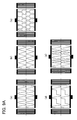
- Fig. 9A is a diagram showing examples (Part 1) of various changing patterns of the weighting in the weighted overlapping regions as embodiments of the invention;
- Fig. 9B is a diagram showing examples (Part 2) of various changing patterns of the weighting in the weighted overlapping regions as embodiments of the invention;
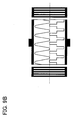
- Fig. 9C is a diagram showing examples (Part 3) of various changing patterns of the weighting in the weighted overlapping regions as embodiments of the invention;
- Fig. 10 is a diagram describing positions of the weighted overlapping regions A, B from a relationship with the aperture length of the interdigital transducer;
- Fig. 11A is a diagram showing a characteristic of a 3IDT resonator filter manufactured experimentally on a Li2B4O7 substrate; and
- Fig. 11B is an enlarged view of the inside of the band of Fig. 11A.
- An embodiment of the invention will now be described with reference to the drawings. It is to be appreciated that the embodiment is for the purpose of describing the invention and that the technical scope of the invention is not limited thereto.
- Fig. 3 is a diagram showing a configuration of an embodiment of the invention.
- As shown above in Fig. 1 and Fig. 2, in a surface acoustic wave apparatus with a pair of
reflection electrodes reflection electrodes reflection electrodes IDT 1 is formed on a piezoelectric substrate not shown, such as LiTaO3, LiNbO3, Li2B4O7 and quartz. - As a feature, the IDT 1 is configured by disposing a plurality of comb-shaped electrodes respectively connected to common electrodes (bus bars) 1a, 1b to be interleaved and has a first overlapping region A and a second overlapping region B where the interleaving of the plurality of comb-shaped electrodes is weighted along a propagation direction of a surface acoustic wave (a direction of an arrow of the figure).
- A plurality of comb-shaped electrode fingers constituting the IDT1 is connected to the common electrodes (bus bars) 1a, 1b opposite to each other and the electrode fingers having adjacent overlapping portions contribute to the surface acoustic wave excitation.
- The first overlapping region A and the second overlapping region B can be defined from the relationship of the comb-shaped electrodes contributing to such surface acoustic wave excitation.
- In Fig. 3, the first overlapping region A is a region from an electrode finger end of a comb-shaped
electrode 100 which has an electrode finger end closest to the secondcommon electrode 1b side among drive electrodes connected to the first common electrode (bus bar) 1a of a pair of the common electrodes, to an electrode finger end of a comb-shapedelectrode 101 which has an electrode finger end closest to the firstcommon electrode 1a side among a plurality of comb-shaped electrodes connected to the firstcommon electrode 1a of the pair of the common electrodes. - On the other hand, the second overlapping region B is a region from an electrode finger end of a comb-shaped
electrode 111 which has an electrode finger end closest to the firstcommon electrode 1a side among a plurality of comb-shaped electrodes connected to the secondcommon electrode 1b of the pair of the common electrodes, to an electrode finger end of a comb-shapedelectrode 110 which has an electrode finger end closest to the secondcommon electrode 1b side among a plurality of comb-shaped electrodes connected to the secondcommon electrode 1b of the pair of the common electrodes. - In the overlapping regions A and B (hereinafter, referred to as weighted overlapping regions A and B), weighting is performed such that the excitation intensity is gradually reduced toward outside in the direction vertical (transverse) to the SAW propagation direction of the
IDT 1. - Therefore, when combining the overlapping region A and the overlapping region B, the excitation intensity distribution of the surface acoustic wave is in a
shape 10 approximate to a basictransverse mode 10a. In this way, only the basictransverse mode 10a is generated and higher-order transverse modes are suppressed. - On the other hand, as shown in Fig. 4, the weighting changes in the overlapping regions A and B can be approximated to envelope curves I, II. Therefore, the overlapping-length weighting envelope curve II in the second overlapping region B has a shape of the overlapping-length weighting envelope curve I in the first overlapping region A translated (i.e. shifted) transverse to the propagation direction (an arrow III of the figure) of the surface acoustic wave.
- Although the overlapping-lengths of the electrode fingers, i.e., sizes of overlapping (crossing)
portions 11a are uneven between adjacent overlapping-lengths, since the difference in the unevenness is generally small relative to the overlapping-length of the overlapping region A, adistribution 11 is maintained in an almost rectangular shape along the propagation direction of the overlapping-lengths. - As a result, the excitation intensity is maintained in a rectangular shape approximate to the normal (non-apodized) IDT in the arrow direction III, i.e., the propagation direction of the surface acoustic wave.
- As described above, according to the invention, the spurious due to the higher-order transverse modes is suppressed and the same characteristics as the normal (non-apodized) electrodes can be achieved.
- Although the
bus bars - In Fig. 5, the
common electrodes common electrodes electrodes 1c in the overlapping regions A and B. - Fig. 6 is an example that the
common electrodes gaps 1d. - Discussion will be made of changing patterns of the weighting in the overlapping regions A, B.
- In Figs. 7A and 7B, an overlapping-length
weighting envelope curve 21 in the second overlapping regions B has a shape mirror-symmetrical to an overlapping-lengthweighting envelope curve 20 in the first overlapping region A relative to an axis of the propagation direction of the surface acoustic wave and, in this example, minimum peaks and maximum peaks are generated in the distribution of the overlapping-lengths along the propagation direction, as shown in Fig. 7B. - The pattern of the change in the weighting according to the invention is not limited to the mirror symmetry as shown in Fig. 7A. Fig. 8 is a diagram describing a relationship between an overlapping-length weighting envelope curve in the second overlapping region B and an overlapping-length weighting envelope curve in the first overlapping region A. The overlapping-length
weighting envelope curve 21 in the second overlapping region B has a shape of the overlapping-lengthweighting envelope curve 20 in the first overlapping region A translated transverse to the propagation direction of the surface acoustic wave as well as translated in the propagation direction, as shown by arrows. - With such an envelope curve shape pattern, minimum peaks and maximum peaks are also generated as shown in Fig. 7B.
- Although the repeating cycles of the overlapping-length weighting envelope curves 20, 21 are depicted longer for convenience in Fig. 7 and, in such a case, since unevenness is generated in the distribution of the overlapping-lengths along the propagation direction, the distribution does not approximate to a rectangular shape such as the
distribution 11 of Fig. 3, the distribution of the overlapping-lengths along the propagation direction is approximated to a rectangular shape as the repeating cycles of the overlapping-length weighting becomes shorter and the same characteristics as the normal (non-apodized) IDT can be realized. - In the above embodiments, as a changing pattern of the weighting in the first and second overlapping regions A, B, an example has been shown which has been changed along the SIN curve shown in Fig. 3. However, the application of the invention is not limited to such embodiments.
- In Figs. 9A, 9B and 9C, as embodiments of the invention (
Part 1, Part 2, part 3), various examples of the weighting in the weighted overlapping regions A, B are shown as envelope curve patterns thereof. - In Fig. 9A, overlapping-length weighting envelope curves of (a) is a COS (or SIN) periodic function f(x) and the same as the embodiment shown in Fig. 3. This is an example of translating the first overlapping-length weighting envelope curve along the perpendicular to the propagation direction of the surface acoustic wave.
- (b) is an example of representing the overlapping-length weighting envelope curve as a periodic function of a triangular wave. (c) is a periodic function alternating 1 and 0 values. (d) is an example of performing the weighting to a portion of the IDT, rather than the entire area thereof. (e) is an example of a combination of different functions. In such embodiments (b) to (e), a relationship between the first overlapping-length weighting envelope curve and the second overlapping-length weighting envelope curve is characterized in that the second overlapping-length weighting envelope curve has a shape of the first overlapping-length weighting envelope curve translated in the direction transverse to the propagation direction of the surface acoustic wave, as is the case with the embodiment (a).
- With regard to the embodiments (a) to (e), as shown in Fig. 8, a shape pattern may be formed as the first overlapping-length weighting envelope curve translated in the direction transverse to the propagation direction of the surface acoustic wave as well as translated in the propagation direction of the surface acoustic wave.
- An example shown in Fig. 9B is an example formed with a changing pattern of the weighting in the first overlapping region A and a different changing pattern of the weighting in the second overlapping region B. In such an example, since the distribution of the overlapping-lengths approximates to a rectangular shape, the effect of the invention can be obtained as well.
- The embodiments shown in Figs. 9A and 9B are examples having two (2) or more changing points in the changing pattern of the weighting.
- The invention is not limited to such a condition. In other words, examples of Fig. 9C are examples having only one (1) changing point in the changing pattern of the weighting. In Fig. 9C (a), a changing
pattern 20 of the weighting envelope curve in the first overlapping region A has only one (1) changing point and a changingpattern 21 of the weighting envelope curve in the second overlapping region B is a shape pattern of the changingpattern 20 translated in the direction transverse to the propagation direction of the surface acoustic wave. - In Fig. 9C (b), a changing
pattern 20 of the weighting envelope curve in the first overlapping region A has only one (1) changing point and a changingpattern 21 of the weighting envelope curve in the second overlapping region B is a shape pattern of the changingpattern 20 translated in the direction transverse to the propagation direction of the surface acoustic wave as well as translated in the propagation direction of the surface acoustic wave. - In Fig. 9C (c), changing
patterns patterns - Although each of the above embodiments shows the case that each of the weighted overlapping regions A, B is 50 % of the aperture length of the interdigital transducer (IDT) 1, the application of the invention is not limited to such a case.
- An example shown in Fig. 10 is the case that at least one of the weighted overlapping regions A, B is greater than 50 % of the aperture length of the
IDT 1. Although a loss is aggravated as the overlapping amount between the weighted overlapping regions A, B is increased, the same effect can be obtained from a viewpoint of the suppressing of the transverse modes. - In any case of such weighting, the requirements of the invention are satisfied and the effect of the invention can be obtained.
- Fig. 11A shows a characteristic of a 3IDT resonator filter manufactured experimentally on a Li2B4O7 substrate. Fig. 11B is an enlarged view of the inside of the band of Fig. 11A. In the figures, a dashed line is a characteristic of the normal (non-apodized) IDT and a solid line is a characteristic in the case of applying the invention.
- A COS function is used for the weighting and the 3IDT resonator filter is weighted as shown in Fig. 3. Although compensation is performed with a matching circuit in order to obtain impedance equivalent to the case of the normal (non-apodized) IDT since impedance is changed by the weighting of the IDT, the spuriae can be suppressed and a bandwidth and an out-of-band damping characteristic can be achieved as is the case with the normal (non-apodized) IDT.
- As set forth hereinabove, according to the invention, transverse-mode effects can be suppressed and characteristics can be achieved which are the same as normal (non-apodized) electrodes. In this way, a SAW resonator and a SAW resonator filter can be designed which have a high degree of freedom and excellent characteristics.
Claims (11)
- A surface acoustic wave apparatus comprising at least one interdigital transducer, the interdigital transducer disposed such that a plurality of comb-shaped electrodes respectively connected to a pair of common electrodes are interleaved,
wherein a region with the plurality of interleaved comb-shaped electrodes is formed with two regions which are a first overlapping region and a second overlapping region with overlapping-lengths weighted along a propagation direction of a surface acoustic wave,
wherein the first overlapping region and the second overlapping region are in contact or overlapped in a direction transverse to the propagation direction of the surface acoustic wave, and
wherein in either the first or the second overlapping region, an overlapping-length weighting envelope curve has at least two or more changing points in the propagation direction of the surface acoustic wave. - The surface acoustic wave apparatus according to claim 1,
wherein the overlapping-length weighting envelope curve in the second overlapping region has a shape which is mirror-symmetrical to an overlapping-length weighting envelope curve in the first overlapping region relative to an axis of the propagation direction of the surface acoustic wave. - The surface acoustic wave apparatus according to claim 1,
wherein the overlapping-length weighting envelope curve in the second overlapping region has a shape which is mirror-symmetrical to an overlapping-length weighting envelope curve in the first overlapping region relative to an axis of the propagation of the surface acoustic wave and which is translated in the propagation direction. - A surface acoustic wave apparatus comprising at least one interdigital transducer, the interdigital transducer disposed such that a plurality of comb-shaped electrodes respectively connected to a pair of common electrodes are interleaved,
wherein a region with the plurality of interleaved comb-shaped electrodes is formed with two regions which are a first overlapping region and a second overlapping region with overlapping-lengths weighted along the propagation direction of the surface acoustic wave,
wherein the first overlapping region and the second overlapping region are in contact or overlapped in a direction transverse to the propagation direction of the surface acoustic wave,
wherein each of the overlapping-length weighting envelope curves in the first and the second overlapping regions has only one changing point in the propagation direction of the surface acoustic wave, and
wherein the changing points of overlapping-length weighting envelope curves in the first and the second overlapping regions have the same direction in the propagation direction of the surface acoustic wave. - The surface acoustic wave apparatus according to any preceding claim,
wherein the overlapping-length weighting envelope curve of either the first or the second overlapping region forms a shape represented by a periodic function f(x), assuming that the propagation direction of the surface acoustic wave is a variable x. - The surface acoustic wave apparatus according to claim 1 or 4,
wherein the overlapping-length weighting envelope curve in the second overlapping region has a shape of an overlapping-length weighting envelope curve in the first overlapping region translated transversely to the propagation direction of the surface acoustic wave. - The surface acoustic wave apparatus according to claim 1 or 4,
wherein the overlapping-length weighting envelope curve in the second overlapping region has a shape of an overlapping-length weighting envelope curve in the first overlapping region translated transversely to the propagation direction of the surface acoustic wave as well as translated in the propagation direction. - The surface acoustic wave apparatus according to claim 1 or 4,
wherein the overlapping-length weighting envelope curve in the first overlapping region and the overlapping-length weighting envelope curve in the second overlapping region have shapes different from each other. - The surface acoustic wave apparatus according to any preceding claim,
wherein a size of each of the first overlapping region and the second overlapping region is set to 50 % of the aperture length of the interdigital transducer. - The surface-acoustic wave apparatus according to any preceding claim,
wherein the common electrodes have a shape corresponding to the overlapping-length weighting envelope curves in the first and second overlapping regions. - The surface acoustic wave apparatus according to claim 1 or 4,
wherein the first overlapping region is a region from an electrode finger end of a comb-shaped electrode whose electrode finger end is closest to a second common electrode among a plurality of comb-shaped electrodes connected to a first common electrode of the pair of common electrodes, to an electrode finger end of a comb-shaped electrode whose electrode finger end is closest to the first common electrode among the plurality of comb-shaped electrodes connected to the first common electrode of the pair of common electrodes, and
wherein the second overlapping region is a region from an electrode finger end of a comb-shaped electrode whose electrode finger end is closest to the first common electrode among a plurality of comb-shaped electrodes connected to the second common electrode of the pair of the common electrodes, to an electrode finger end of a comb-shaped electrode whose electrode finger end is closest to the second common electrode among the plurality of comb-shaped electrodes connected to the second common electrode of the paid of common electrodes.
Applications Claiming Priority (1)
| Application Number | Priority Date | Filing Date | Title |
|---|---|---|---|
| JP2005241195A JP2007060108A (en) | 2005-08-23 | 2005-08-23 | Surface acoustic wave device |
Publications (2)
| Publication Number | Publication Date |
|---|---|
| EP1770858A2 true EP1770858A2 (en) | 2007-04-04 |
| EP1770858A3 EP1770858A3 (en) | 2007-04-18 |
Family
ID=37762504
Family Applications (1)
| Application Number | Title | Priority Date | Filing Date |
|---|---|---|---|
| EP06250971A Withdrawn EP1770858A3 (en) | 2005-08-23 | 2006-02-23 | Surface acoustic wave apparatus |
Country Status (5)
| Country | Link |
|---|---|
| US (1) | US7482896B2 (en) |
| EP (1) | EP1770858A3 (en) |
| JP (1) | JP2007060108A (en) |
| CN (1) | CN1921300B (en) |
| TW (1) | TWI322567B (en) |
Families Citing this family (15)
| Publication number | Priority date | Publication date | Assignee | Title |
|---|---|---|---|---|
| WO2007108269A1 (en) * | 2006-03-17 | 2007-09-27 | Murata Manufacturing Co., Ltd. | Elastic wave resonator |
| DE102010034121A1 (en) * | 2010-08-12 | 2012-02-16 | Epcos Ag | Working with acoustic waves device with reduced temperature response of the frequency position and method of manufacture |
| DE102014111828A1 (en) * | 2014-08-19 | 2016-02-25 | Epcos Ag | One-port resonator operating with surface acoustic waves |
| CN104990638B (en) * | 2015-06-30 | 2018-06-22 | 深圳华远微电科技有限公司 | A kind of chip based on radio temperature sensor |
| CN108566176B (en) * | 2018-04-12 | 2021-04-06 | 无锡市好达电子股份有限公司 | Clutter suppression method for surface acoustic wave resonator |
| DE102018118005A1 (en) * | 2018-07-25 | 2020-01-30 | RF360 Europe GmbH | SAW device with an inclined resonator |
| DE102018118003B4 (en) * | 2018-07-25 | 2025-04-24 | Rf360 Singapore Pte. Ltd. | SAW device with an inclined resonator |
| US11171627B2 (en) | 2018-10-01 | 2021-11-09 | Qorvo Us, Inc. | Wave apodization for guided SAW resonators |
| DE102018130144A1 (en) * | 2018-11-28 | 2020-05-28 | RF360 Europe GmbH | Electroacoustic resonator and RF filter |
| SG10201911416RA (en) | 2018-12-03 | 2020-07-29 | Skyworks Solutions Inc | Acoustic Wave Device With Transverse Spurious Mode Suppression |
| JP7411334B2 (en) * | 2019-03-20 | 2024-01-11 | 太陽誘電株式会社 | elastic wave resonator |
| DE102019111320A1 (en) * | 2019-05-02 | 2020-11-05 | RF360 Europe GmbH | Inclined acoustic transducer with improved electro-acoustic coupling |
| US12143090B2 (en) | 2021-10-29 | 2024-11-12 | Qorvo Us, Inc. | Surface acoustic wave (SAW) structures with transverse mode suppression |
| CN114054429B (en) * | 2022-01-11 | 2022-04-01 | 北京东方金荣超声电器有限公司 | Megasonic cleaning system for large-size wafer |
| US12355424B2 (en) * | 2022-09-21 | 2025-07-08 | Rf360 Singapore Pte. Ltd. | Electroacoustic resonator |
Citations (4)
| Publication number | Priority date | Publication date | Assignee | Title |
|---|---|---|---|---|
| JPH0722898A (en) | 1993-06-30 | 1995-01-24 | Murata Mfg Co Ltd | Surface acoustic wave element |
| JPH0728195B2 (en) | 1986-02-28 | 1995-03-29 | 株式会社東芝 | Surface acoustic wave resonator |
| JPH09270667A (en) | 1996-04-01 | 1997-10-14 | Hiroaki Sato | Surface acoustic wave resonator |
| JP2005241195A (en) | 2004-02-27 | 2005-09-08 | Sanyo Electric Co Ltd | Air conditioning refrigerator |
Family Cites Families (18)
| Publication number | Priority date | Publication date | Assignee | Title |
|---|---|---|---|---|
| GB1430725A (en) * | 1974-08-02 | 1976-04-07 | Mullard Ltd | Acoustic surface wave devices |
| US4005378A (en) * | 1975-11-25 | 1977-01-25 | The United States Of America As Represented By The Secretary Of The Air Force | Surface acoustic wave filter |
| US4205285A (en) * | 1978-11-03 | 1980-05-27 | Gte Laboratories Incorporated | Acoustic surface wave device |
| JPS5844808A (en) * | 1981-09-11 | 1983-03-15 | Toshiba Corp | Surface acoustic wave device |
| JPS6041304A (en) * | 1983-08-16 | 1985-03-05 | Oki Electric Ind Co Ltd | Oscillator of surface acoustic wave |
| US4673901A (en) * | 1984-10-26 | 1987-06-16 | Siemens Aktiengesellschaft | Electrical filter operating with acoustic waves |
| JPS61164317A (en) * | 1985-01-14 | 1986-07-25 | シーメンス、アクチエンゲゼルシヤフト | Electric surface acoustic wave filter |
| DE3519853A1 (en) * | 1985-06-03 | 1986-12-04 | Siemens AG, 1000 Berlin und 8000 München | ELECTRIC FILTER WITH ACOUSTIC SHAFTS |
| JPS6326016A (en) | 1986-08-06 | 1988-02-03 | Hitachi Ltd | surface acoustic wave device |
| JPH0477104A (en) * | 1990-07-17 | 1992-03-11 | Nec Corp | Surface acoustic wave device |
| JPH0728195A (en) | 1993-07-15 | 1995-01-31 | Konica Corp | Silver halide sensitive material |
| JPH09294046A (en) * | 1996-04-25 | 1997-11-11 | Meidensha Corp | Transversal surface acoustic wave band pass filter |
| JP3068035B2 (en) | 1997-05-26 | 2000-07-24 | 日本電気株式会社 | Surface acoustic wave device |
| JP3863712B2 (en) * | 2000-09-06 | 2006-12-27 | 株式会社日立製作所 | Surface acoustic wave resonator |
| DE10135871B4 (en) * | 2001-07-24 | 2012-10-25 | Epcos Ag | Surface wave converter with improved suppression of spurious excitation |
| JP2003179461A (en) * | 2001-09-28 | 2003-06-27 | Seiko Epson Corp | Vertical multi-mode SAW filter |
| US7221074B2 (en) * | 2003-11-18 | 2007-05-22 | Fujitsu Media Devices Limited | Surface acoustic device |
| JP2006121634A (en) * | 2004-10-19 | 2006-05-11 | Kazuhiko Yamanouchi | Surface acoustic surface wave resonator, and electronic device using it |
-
2005
- 2005-08-23 JP JP2005241195A patent/JP2007060108A/en active Pending
-
2006
- 2006-02-23 TW TW095106104A patent/TWI322567B/en not_active IP Right Cessation
- 2006-02-23 EP EP06250971A patent/EP1770858A3/en not_active Withdrawn
- 2006-03-06 US US11/367,555 patent/US7482896B2/en not_active Expired - Fee Related
- 2006-05-25 CN CN2006100827683A patent/CN1921300B/en not_active Expired - Fee Related
Patent Citations (4)
| Publication number | Priority date | Publication date | Assignee | Title |
|---|---|---|---|---|
| JPH0728195B2 (en) | 1986-02-28 | 1995-03-29 | 株式会社東芝 | Surface acoustic wave resonator |
| JPH0722898A (en) | 1993-06-30 | 1995-01-24 | Murata Mfg Co Ltd | Surface acoustic wave element |
| JPH09270667A (en) | 1996-04-01 | 1997-10-14 | Hiroaki Sato | Surface acoustic wave resonator |
| JP2005241195A (en) | 2004-02-27 | 2005-09-08 | Sanyo Electric Co Ltd | Air conditioning refrigerator |
Also Published As
| Publication number | Publication date |
|---|---|
| JP2007060108A (en) | 2007-03-08 |
| TWI322567B (en) | 2010-03-21 |
| CN1921300A (en) | 2007-02-28 |
| US7482896B2 (en) | 2009-01-27 |
| US20070046400A1 (en) | 2007-03-01 |
| CN1921300B (en) | 2010-05-12 |
| EP1770858A3 (en) | 2007-04-18 |
Similar Documents
| Publication | Publication Date | Title |
|---|---|---|
| JP6595659B2 (en) | Elastic wave device, duplexer, and communication device | |
| US7939989B2 (en) | Piston mode acoustic wave device and method providing a high coupling factor | |
| US7522021B2 (en) | Surface acoustic wave apparatus | |
| US7482896B2 (en) | Surface acoustic wave apparatus | |
| WO2018168836A1 (en) | Acoustic wave element, acoustic wave filter device, and multiplexer | |
| US8896399B2 (en) | Acoustic wave device and module including a dielectric film with an inclined upper surface | |
| KR20180123562A (en) | Seismic wave device | |
| JP4100249B2 (en) | Surface acoustic wave device, communication device | |
| WO2021153734A1 (en) | Elastic wave device and ladder filter having same | |
| US6650207B1 (en) | Longitudinally coupled surface acoustic wave filter with linearly weighted reflectors | |
| KR100697763B1 (en) | Surface acoustic wave device | |
| US7372347B2 (en) | Surface acoustic wave device | |
| JP6585459B2 (en) | Elastic wave device, duplexer, and communication device | |
| EP1233512A2 (en) | Longitudinal coupled multiple mode surface acoustic wave filter | |
| JP3745847B2 (en) | Structure of dual mode SAW filter | |
| CN118764007B (en) | Elastic wave resonator and elastic wave filter device | |
| JPH05335881A (en) | Longitudinal dual mode surface acoustic wave filter | |
| JPH10261935A (en) | Surface acoustic wave element | |
| KR100762053B1 (en) | Surface acoustic wave device | |
| JP3724901B2 (en) | Structure of dual mode SAW filter | |
| KR20100041844A (en) | Elastic boundary wave device and communication equipment using the same | |
| JP4200629B2 (en) | Vertically coupled multimode SAW filter | |
| JP4548305B2 (en) | Dual-mode surface acoustic wave filter | |
| JP2025110764A (en) | Longitudinal-Coupled Dual-Mode Surface Acoustic Wave Filters |
Legal Events
| Date | Code | Title | Description |
|---|---|---|---|
| PUAI | Public reference made under article 153(3) epc to a published international application that has entered the european phase |
Free format text: ORIGINAL CODE: 0009012 |
|
| PUAL | Search report despatched |
Free format text: ORIGINAL CODE: 0009013 |
|
| AK | Designated contracting states |
Kind code of ref document: A2 Designated state(s): AT BE BG CH CY CZ DE DK EE ES FI FR GB GR HU IE IS IT LI LT LU LV MC NL PL PT RO SE SI SK TR |
|
| AX | Request for extension of the european patent |
Extension state: AL BA HR MK YU |
|
| AK | Designated contracting states |
Kind code of ref document: A3 Designated state(s): AT BE BG CH CY CZ DE DK EE ES FI FR GB GR HU IE IS IT LI LT LU LV MC NL PL PT RO SE SI SK TR |
|
| AX | Request for extension of the european patent |
Extension state: AL BA HR MK YU |
|
| 17P | Request for examination filed |
Effective date: 20071017 |
|
| AKX | Designation fees paid |
Designated state(s): DE FR GB |
|
| RAP1 | Party data changed (applicant data changed or rights of an application transferred) |
Owner name: TAIYO YUDEN CO., LTD. Owner name: FUJITSU MEDIA DEVICES LIMITED |
|
| 17Q | First examination report despatched |
Effective date: 20101027 |
|
| RAP1 | Party data changed (applicant data changed or rights of an application transferred) |
Owner name: TAIYO YUDEN CO., LTD. |
|
| RIC1 | Information provided on ipc code assigned before grant |
Ipc: H03H 9/64 20060101ALI20110728BHEP Ipc: H03H 9/145 20060101ALI20110728BHEP Ipc: H03H 9/02 20060101AFI20110728BHEP |
|
| GRAP | Despatch of communication of intention to grant a patent |
Free format text: ORIGINAL CODE: EPIDOSNIGR1 |
|
| STAA | Information on the status of an ep patent application or granted ep patent |
Free format text: STATUS: THE APPLICATION IS DEEMED TO BE WITHDRAWN |
|
| 18D | Application deemed to be withdrawn |
Effective date: 20120217 |