EP1770751B1 - Cluster tool for microscopic processing of samples - Google Patents
Cluster tool for microscopic processing of samples Download PDFInfo
- Publication number
- EP1770751B1 EP1770751B1 EP06121304.7A EP06121304A EP1770751B1 EP 1770751 B1 EP1770751 B1 EP 1770751B1 EP 06121304 A EP06121304 A EP 06121304A EP 1770751 B1 EP1770751 B1 EP 1770751B1
- Authority
- EP
- European Patent Office
- Prior art keywords
- sample
- tool
- vacuum
- tools
- multiple tools
- Prior art date
- Legal status (The legal status is an assumption and is not a legal conclusion. Google has not performed a legal analysis and makes no representation as to the accuracy of the status listed.)
- Expired - Fee Related
Links
Images

Classifications
-
- H—ELECTRICITY
- H01—ELECTRIC ELEMENTS
- H01J—ELECTRIC DISCHARGE TUBES OR DISCHARGE LAMPS
- H01J37/00—Discharge tubes with provision for introducing objects or material to be exposed to the discharge, e.g. for the purpose of examination or processing thereof
- H01J37/02—Details
- H01J37/20—Means for supporting or positioning the objects or the material; Means for adjusting diaphragms or lenses associated with the support
-
- H—ELECTRICITY
- H01—ELECTRIC ELEMENTS
- H01J—ELECTRIC DISCHARGE TUBES OR DISCHARGE LAMPS
- H01J37/00—Discharge tubes with provision for introducing objects or material to be exposed to the discharge, e.g. for the purpose of examination or processing thereof
- H01J37/02—Details
- H01J37/18—Vacuum locks ; Means for obtaining or maintaining the desired pressure within the vessel
-
- H—ELECTRICITY
- H01—ELECTRIC ELEMENTS
- H01J—ELECTRIC DISCHARGE TUBES OR DISCHARGE LAMPS
- H01J37/00—Discharge tubes with provision for introducing objects or material to be exposed to the discharge, e.g. for the purpose of examination or processing thereof
- H01J37/02—Details
- H01J37/22—Optical or photographic arrangements associated with the tube
- H01J37/226—Optical arrangements for illuminating the object; optical arrangements for collecting light from the object
-
- H—ELECTRICITY
- H01—ELECTRIC ELEMENTS
- H01J—ELECTRIC DISCHARGE TUBES OR DISCHARGE LAMPS
- H01J37/00—Discharge tubes with provision for introducing objects or material to be exposed to the discharge, e.g. for the purpose of examination or processing thereof
- H01J37/26—Electron or ion microscopes; Electron or ion diffraction tubes
- H01J37/28—Electron or ion microscopes; Electron or ion diffraction tubes with scanning beams
-
- H—ELECTRICITY
- H01—ELECTRIC ELEMENTS
- H01J—ELECTRIC DISCHARGE TUBES OR DISCHARGE LAMPS
- H01J2237/00—Discharge tubes exposing object to beam, e.g. for analysis treatment, etching, imaging
- H01J2237/20—Positioning, supporting, modifying or maintaining the physical state of objects being observed or treated
- H01J2237/202—Movement
- H01J2237/20214—Rotation
Definitions
- the present invention relates to systems for efficient microscopic processing of samples using multiple tools.
- Samples studied in science and industry are typically subject to a variety of different processing operations including imaging, material analysis, and modifying the sample.
- a sample may be polished, coated with carbon, and then bombarded with an electron beam in a scanning electron microscope (SEM) to analyze the sample composition and to form magnified image.
- SEM scanning electron microscope
- the tools that are used for these steps are typically stand-alone tools, that is, tools that are purchased separated, typically from different manufacturers, and that are not connected to each other.
- moving samples between tools is done manually or using awkward add-on robotics.
- a polishing machine can be used to polish a sample. The sample is then removed from the polishing machine, cleaned, and manually placed into an evaporator for deposition of a carbon layer onto the sample. The sample is then manually removed from the evaporator and placed into an electron microscope for observation.
- Some processes such as scanning electron microscopy and focused ion beam etching, require that the sample be maintained in a vacuum in a sample chamber.
- the typical method for moving a sample into and out of the sample chamber is to slowly vent the chamber to the atmosphere and allow it to reach atmospheric pressure. The chamber is then opened, the previous sample is removed, a new sample inserted, and the sample chamber re-evacuated.
- the time required to vent the sample chamber to atmosphere and then to re-evacuate the sample chamber is significant and can preclude the use of vacuum tools in a fast-paced production line.
- U.S. Pat. Pub. No. 2005/0173380 to Carbone describes a rapid prototyping system that includes a vacuum chamber that contains an electron gun that creates a molten pool into which a wire is fed to build up material and a spindle with a tool carousel for machining the deposit. A rotating pallet changer rotates to move the work piece between the two tools.
- EP0003073 to Sciaky describes an electron beam welding system in which a work piece is deposited into a depression in a rotating platform and rotated under the electron beam. Sealable pockets evacuate the depression as it rotates into position under the beam, eliminating an on-rush of air that disturbs metal particles produced in the welding process preventing the metal particles from damaging the mechanism.
- Another disadvantage of using stand alone tools is the expense of individual tools. A complete line of tools for sample processing, analysis, and imaging may require many expensive tools that are available only to well-funded laboratories. Still another disadvantage of using multiple stand alone tools is the amount of space required in a laboratory or a fabrication facility. Tools for microscopic processing are often located in clean rooms, and space within clean rooms is costly, both for construction and for maintaining the required cleanliness. The number of tools, and therefore the expense, can be reduced if multiple tools are combined in a single tool. Such multi-functional tools are known, but the integration of functionalities typically compromises the performance level of each of the functions.
- An apparatus for microscopic processing of samples according to the present invention is defined in claim 1.
- a method of using such an apparatus is defined in claim 11.
- a method of using multiple tools to perform microscopic processing according to the present invention is defined in claim 12.
- An object of the invention is to provide a system that is adapted to efficiently process a sample using multiple tools.
- the system uses a carousel to move a sample between tools and provides reduced processing time and equipment costs.
- the invention comprises a single platform that includes multiple positions for accepting a number of tools.
- the platform includes a carousel, that is, a rotating platform that allows for transporting one or more samples between the various tools.
- the tools preferably have their working areas at a fixed radius with respect to the carousel axis, so that the sample can be rapidly moved between the working areas of the various tools.
- the carousel enables a sample to be rapidly processed by multiple tools by facilitating the transport of the sample between tools.
- the sample can be rapidly transitioned from an atmospheric environment to the vacuum conditions that are required for operation of some tools.
- one or more samples are positioned in one or more recesses in a carousel base.
- the tools include one or more tools that are maintained in one or more vacuum chambers, each chamber having a bottom that forms a slidable vacuum seal with the carousel base.
- the sample in the recess can be slid under the vacuum seal, thereby admitting the sample to the vacuum chamber without opening the chamber to the environment.
- the small amount of air in the recess that enters the vacuum chamber with the sample can be evacuated from the vacuum chamber relatively quickly, if necessary.
- the evacuation can be further expedited by using vacuum buffers, that is, pre-evacuated volumes that can suck air form the recess before it enters the vacuum chamber, or from the vacuum chamber itself.
- FIG. 1 shows a preferred embodiment of a cluster system 100 of the present invention.
- System 100 includes a rotatable sample platform, referred to as a carousel 102, above which multiple tools 104 are mounted around a circle 106 for processing one or more samples 108.
- Carousel 102 is preferably rotated using an electric motor with feedback for precise rotation.
- the carousel can also be precisely positioned using notches, detents, or other means to indicate, and maintain the carousel at, the desired angular position.
- the tools 104 are supported on non-rotating supports (not shown) adjacent the carousel 102, for example, resting on the floor, resting on a non-rotating table top, or suspended from above the carousel, so that the carousel 102 can rotate a sample between the tools 104.
- a sample to be processed is supported on the rotatable carousel.
- the tools are typically tools used for microscopic processing of samples, that is, tools that image or alter the sample on a scale of smaller than a millimeter, more preferably smaller than 100 microns, or smaller than 10 microns.
- Each tool 104 typically has a limited working area within which the sample must be positioned to be processed by the tool.
- Tools 104 are mounted so that the working areas of all tools 104 are located on circle 106, which is centered substantially on a carousel rotation axis 110.
- the sample 108 on the carousel 104 is preferably mounted on a manipulator 114 that can move the sample radially and preferably provides fine adjustment circumferentially and vertically.
- the sample 108 and manipulator 114 can be positioned in a recess in carousel 102 to facilitate moving the sample into and out of certain tools 104.
- carousel 102 can include positions for multiple samples, the multiple sample positions preferably spaced around the carousel at the same relative angular displacements as the tools, thereby permitting multiple tools to operate on multiple samples simultaneously.
- a micrometer spindle 120 allows fine adjustment of the angular position of axis of rotation 110. When multiple sample positions are used and multiple tools are used simultaneously, micrometer spindle cannot be used to adjust individual sample positions, because it will move all samples on the carousel at the same time. If multiple samples are used, individual sample positions can be adjusted by using individual sample manipulators 114 at each sample position. In another embodiment, the tools themselves can be moved to adjust their working areas to the sample location, instead of moving the sample to a fixed working area of the tool. Any combination of the adjusting position of the carousel, the individual sample, and individual tools can be used.
- system 100 By facilitating the transition between tools 104, system 100 reduces the need for multi-functional tools, which typically compromises the performance in each of its functions.
- Each tool can be one link in the chain of processing, including analyzing, imaging, altering, or other operations.
- the invention does not exclude the use of combination tools as part of system 100.
- Some of the tools 104 may include sample vacuum chambers and require the sample to be maintained in a vacuum for operation. In such cases, it is preferable to minimize the time required to evacuate the sample chamber, to reduce overall processing time.
- Typical tools that can be used with system 100 include imaging tools, such as light microscopes, scanning probe microscopes (such as atomic force microscopes, scanning tunneling microscopes and stylus nanoprofilometers), and electron microscopes; analytical tools such as X-ray fluorescence or raman spectrometers; mechanical processing tools, for example, for coating, polishing, cutting, or indenting; and illumination tools, such as for ultra violet curing.
- imaging tools such as light microscopes, scanning probe microscopes (such as atomic force microscopes, scanning tunneling microscopes and stylus nanoprofilometers), and electron microscopes
- analytical tools such as X-ray fluorescence or raman spectrometers
- mechanical processing tools for example, for coating, polishing, cutting, or indenting
- illumination tools such as for ultra violet curing.
- the invention is not limited to any specific tools.
- the tools can be relatively low-cost tools, typically desktop versions of more expensive high-end systems. Costs can also be reduced by providing common support utilities for the tools, such as providing vacuum
- Embodiments of the invention can facilitate processing by the various tools by providing a single sample coordinate system, thereby facilitating correlation of information from the individual tools.
- a tangent to the circle 106 at each tool can be defined as the X-axis of that tool, and a radius at that tool can be defined as the Y-axis.
- the invention reduces the time between successive process steps on different tools. Some samples change over time. For example, a process that exposes a surface may allow the surface to begin to oxidize. By facilitating rapid transition between tools, time dependent sample changes between operations are reduced or eliminated.
- FIG. 2 shows the embodiment of FIG. 1 with specific tools placed around carousel 102.
- the tools include a desktop scanning electron microscope (SEM) 210, a polishing machine 212, a light microscope 214 and an X-ray fluorescence (XRF) tool 216.
- SEM desktop scanning electron microscope
- the tools are supported in such a manner that carousel 106 is free to rotate under the tools.
- the SEM could be, for example, one described by John Callas in "Miniature Scanning Electron Microscope," NASA Tech Briefs, Vol. 23, No. 11 , and Jet Propulsion Laboratories (JPL) Report No. NP020499.
- the polishing machine 212 and the light microscope 214 operate on the sample 108 in atmosphere.
- the SEM 210 and XRF tool 216 require that the sample be maintained in a vacuum during processing.
- Vacuum lines 217 are used to evacuate sample chambers of the SEM 210 and XRF tool 216. While the tools shown in FIG. 2 are representative, the invention is not limited to those particular tools.
- SEM 210 requires a vacuum of about 10 -5 mbar. Loading a sample into an SEM and removing the air from the SEM to achieve the required vacuum takes time. Strategies that reduce the time required to evacuate the chamber can significantly reduce processing time.
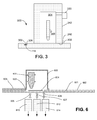
- FIG. 3 shows an apparatus 300 that permits the sample 302 to be moved into a vacuum chamber, such as a vacuum chamber 304 of an SEM 305, without opening vacuum chamber 304 to atmosphere.
- the sample 302 is positioned in a recess 306 in a base 308.
- Base 308 is sufficiently flat to form a vacuum seal with a sliding bearing surface 310 of vacuum chamber 304.
- Base 308 can be, for example, a ground steel flat surface.
- Vacuum chamber 304 includes walls 312 that terminate in sliding bearing surfaces 310. Sliding bearing surfaces 310 can be integral to walls 312 or can be attached to walls 312.
- Sliding bearing surfaces 310 are sufficiently flat to form a vacuum seal with base 308, and can be made, for example, of steel, ceramic, or other material that can be made sufficiently flat and rigid.
- a coating such as Teflon, can optionally be used on one of the surfaces 308 or 310.
- the flatness of the two surfaces is used to create a vacuum-tight seal, typically without requiring the use of o-rings or other elastic vacuum seals.
- the reduced friction coefficient is used to enable movement of the vacuum chamber 304 relative to base 308 despite the high vacuum forces.
- a vacuum pump 320 is used to evacuate chamber 304.
- a vacuum of 5 x 10 -2 mbar was achieved with a 2 to 3 liter/hour pumping speed on a vacuum chamber surface of 130 mm by 50 mm. Frictional forces were found to be less than 15 N. While grease and oil may be used as lubricants in some embodiments, such lubricants are potential sources of contamination.
- System 300 can be used with system 100 ( FIG. 1 ).
- Carousel 102, or a portion thereof, can be made sufficiently smooth to function as base 308.
- Vacuum chamber 304 is held in a fixed position, and carousel 102 is rotated beneath chamber 304.
- various types of sliding vacuum seals are known and can be used.
- Carousel 102 is pressed with sufficient force against the bottom vacuum chamber walls 312 to maintain a vacuum seal.
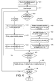
- FIG. 4 shows the steps for performing operations on a sample using a tool that processes the sample in atmosphere and a tool that processes the sample in a vacuum.
- the system of FIG. 3 is used as an example of a tool that processes the sample in a vacuum in the process described below, but the invention is not limited to any specific tool or order of processing between vacuum, atmospheric, and other environmental systems, nor is the invention limited to any particular tools.
- step 401 evacuation of a vacuum chamber 304 of a tool 300 is begun.
- step 402 a sample is loaded onto carousel 102. Multiple samples could be loaded for simultaneous processing, but processing a single sample is described to facilitate understanding of the process. Skilled persons can readily extent the description below to make and use a multiple sample embodiment. Because of the vacuum tight seal between base 308 and sliding bearing surface 310 on carousel 102, the sample can be moved around the carousel and processed by other tools concurrently with, or after, evacuating vacuum chamber 304.
- Decision block 403 indicates that the next steps depend on whether the next processing step is performed in a vacuum or in atmosphere. If the next processing step is performed in atmosphere, the carousel 102 is rotated in step 404 to position the sample 302 within the working area of a first tool.
- step 406 the position of the sample is adjusted, manually or automatically, in the radial direction and vertically using a positioner or manipulator 118.
- the sample position can be adjusted in the circumferential direction either by adjusting the rotational position of carousel 102 using the micrometer 120, or by using manipulator 118.
- the tool processes the sample.
- the tool may be an optical microscope for observing and recording an image of the sample, or a polishing machine to polish the sample.
- Decision block 409 determines whether additional processing of the sample is required. If so, the process returns to step 403 to determine whether the additional processing is vacuum processing or atmosphere processing. If the additional processing is vacuum processing, the carousel is rotated in step 410 to bring the sample into vacuum chamber 304. To reduce processing time, the evacuation of chamber 304 is preferably complete before the sample 108 enters into the chamber 304. As the carousel 102 is rotated, chamber 304 slides over recess 306 in which sample 108 is located, and the sample 108 thereby enters the chamber 304.
- chamber 304 was evacuated prior to rotating sample 302 into chamber 304, air in recess 306 enters chamber 304 as sample 302 is rotated into chamber 304, increasing the pressure in chamber 304.
- step 422 chamber 304 is evacuated.
- the position of the sample 108 is finely adjusted as described above.
- tool 104 processes the sample.
- Environmental scanning electron microscopes which operate at a higher pressure than conventional electron microscopes, can be used as a tool in the invention and can eliminate or further reduce evacuation time.
- Decision block 409 again determined whether additional processing is required on the sample. If so, the processing continues with decision block 403. If no additional operation is required by systems positioned around carousel 102, the carousel is rotated to free the sample and the sample is removed in step 432. Because the bearing contact area between base 308 (as embodied by carousel 102) and sliding bearing surface 310 is preferably wider than recess 306, rotating recess 306 out from under chamber 304 allows little or no air into the chamber 304. Thus, the chamber remains evacuated and ready to use for the next sample. Vacuum pump 320 can be operated as needed to evacuate any air that leaks into chamber 304 between carousel 102 and sliding bearing surface 310.
- decision block 434 it is determined whether additional samples are to be processes. If so, processing is continued by loading the next sample as shown in step 402. It will be understood that if carousel 102 includes multiple sample holders and accommodates multiple samples, a new sample can be placed and rotated to one tool, while a sample already on carousel 102 is rotated to a different tool.
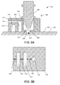
- FIGS. 5A, 5B , and 6 show methods and apparatuses, which are described in U.S. Pat. App. No. 11/169,274 , for reducing the time required to evacuate a sample vacuum chamber.
- FIG. 5A shows an alternative embodiment of a system 500.
- the depicted apparatus comprises a sheet 501 with a smooth surface 502, in which smooth surface 502 includes a hole in the form of a cavity 503 is cut out. A sample 504 is laid in this cavity 503.
- Sheet 501 can be a part of carousel 102.
- a sole plate 505 is placed on the smooth surface 502 and is movable across the smooth surface 502 in a vacuum-tight manner.
- Figure 5B schematically shows the side of the sole plate 505 that seals onto the smooth surface 502.
- the sole plate 505 is provided with hollows that form vacuum buffer cavities or volumes 510, 512 and 514. These vacuum buffer volumes are connected to vacuum pumps (not shown) via the respective shafts 511, 513 and 515.
- An ESEM can analyze a sample at a pressure in the vicinity of the sample of about 10 mbar or less.
- the electron beam 507 produced by the ESEM column 506 probes the sample 504 through a hollow 508 in the sole plate 505.
- the electron beam 507 induces the emission of, for example, radiation such as secondary electrons and X-ray radiation, which can be detected with the aid of detectors (not shown).
- the sole plate 505 Before introducing a sample 504, the sole plate 505 is first slid across the smooth surface 502 in such a manner that the cavity 503 is not covered by the sole plate 505. It is then easy to remove from the cavity 503 any sample that has already been analyzed, and to lay in the cavity a subsequent sample that is to be analyzed.
- the sole plate is slid across the smooth surface, as a result of which the cavity 503 is successively connected to vacuum buffer volumes 514, 512 and 510.
- the volume of the vacuum buffer volumes is a few times greater, e.g. ten times greater, than the volume of the cavity 503.
- the pressure in the cavity will decrease almost instantaneously by a factor of, for example, ten.
- the pressure will hereby be reduced in three steps, each of a factor of ten, for example, so that the pressure decreases in total by a factor of 10 3 .
- the pressure upon introducing the sample was 1 bar
- the pressure is reduced to 1 mbar, which pressure is sufficiently low for analysis with the aid of an ESEM column (and for various other analysis techniques).
- the separation 18 between the surroundings and the first vacuum buffer volume 514 is of such a size that, before the cavity 503 is connected to the first vacuum buffer volume, the cavity is completely covered. In this manner, one prevents the vacuum buffer volume 514 from being momentarily connected to ambient pressure via the cavity 503. This requires that the width of separation 518 be greater than the diameter of cavity 503.
- the separation 519 between the first vacuum buffer volume 514 and the second vacuum buffer volume 512 has a width greater than the diameter of the cavity, just as does the separation 520 between the second vacuum buffer volume 512 and the third vacuum buffer volume 510.
- the hollows in the sole plate 505 that form the vacuum buffer volumes 510 and 512 are asymmetrically formed. It should be clear that embodiments are also possible whereby the hollows are, for example, formed concentrically about the vacuum buffer volume 510.
- the apparatus can be equipped with a different number of vacuum buffer volumes, or one can choose a different ratio between the volume of the cavity and the size of the vacuum buffer volumes.
- each vacuum buffer volume it is not necessary to connect to a separate pump.
- FIG. 6 schematically depicts an apparatus according to the invention whereby a wafer is being analyzed by an analysis column that is movable in a vacuum column.
- the depicted apparatus comprises a sheet 601, which can be part of carousel 102, with a smooth surface 602, in which smooth surface 602 a hole in the form of a cavity 603 has been cut out.
- a sample in the form of a semiconductor wafer 604 is laid in this cavity 603.
- Sole plate 605 is placed on the smooth surface 602 and is movable across the smooth surface 602.
- a vacuum column 609 is mounted, in which vacuum is maintained using non-depicted evacuation means.
- an analysis column such as an ESEM column 606, which is movable within the vacuum column 609 (with the aid of non-depicted moving means).
- the cavity 603 is connected to vacuum valves 625, 626, and 627 that can connect the cavity 603 to vacuum buffer volumes 610, 612 and 614.
- These vacuum buffer means are evacuated by (non-depicted) vacuum pumps.
- the sole plate 605 is first slid across the smooth surface 602 in such a manner that the cavity 603 is not covered by the sole plate 605.
- the vacuum valves 625, 626, and 627 are hereby closed, so that the vacuum buffer volumes 610, 612, 614 are not in vacuum connection with the cavity 603.
- the sole plate 605 is slid across the smooth surface 602 in such a manner that the cavity 603 is completely covered by the sole plate 605, but there is no vacuum connection between the cavity 603 and the vacuum column 609. Thereafter, the cavity 603 is successively connected to the vacuum buffer volumes 610, 612 and 614 by opening and closing the vacuum valves 625, 626 and 627.
- the sole plate 605 is slid across the smooth surface 602 in such a manner that the vacuum column 609 is positioned above the cavity 603.
- the ESEM column 606, which is movable within the vacuum column 609, is thereafter moved to a region of interest of the wafer 604 to be analyzed.
- the invention provides a lower cost alternative to high performance individual machines.
- the lower cost of some embodiments are particularly suitable for educational institutions, low budget laboratories, industrial facilities, such as metal, chemical, pharmaceutical, forensic labs, and hospitals. While embodiments of the invention can use lower cost components, the invention is not limited to using such components.
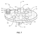
- one tool about the carousel can be a material handling tool, for example, a tool that can load and unload samples from a sample carrier onto one or more sample holders on the carousel.
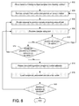
- FIG. 7 shows a material handling tool, a cassette loader/unloader 702. Operation of this embodiment is described with respect to a flowchart in FIG. 8 . Details of the operation, such as evacuating chambers and adjusting the workplace position, which were previously described with respect to FIG. 4 , may also be performed in this embodiment, but are not described again or shown on FIG. 7 .
- step 802 an operator places a carrier 704 containing multiple samples 706, such as a cassette of semiconductor wafers, at a loading position 707 near the cassette loader/unloader 702.
- cassette loader/unloader 702 removes a sample 706 from the cassette and places the sample onto a sample holder 708 on carousel 102.
- carousel 802 is rotated to position sample 706 within the working area of a first tool 104.
- step 808 sample 708 is processed by a first tool 104.
- Decision block 810 shows that if there is another sample to be processed, cassette loader/unloader 702 places another sample onto the carousel 102 at the next sample holder by cassette loader/unloader 702.
- Steps 806 and 808 are then repeated to position and process the new sample.
- Decision block 812 shows that if the first sample is to be processed by an additional tool, when carousel 102 is rotated to bring the new sample into the working area of the area of the first tool, the rotation of the carousel also brings the earlier placed sample into the working area of a second tool.
- step 814 a sample that has completed processing is rotated back to a position near cassette loader/unloader 702, and in step 816 the sample is loaded by cassette loader/unloader 702 back into carrier 704 or into a second carrier.
- step 816 the sample is loaded by cassette loader/unloader 702 back into carrier 704 or into a second carrier.
- any other samples remaining on the carousel are preferably simultaneously positioned under other tools at the same time.
- Decision block 820 shows that if there are samples still on the carousel, they are processed in step 808.
- any additional samples are loaded in step 810, and the processing continues until all samples have been unloaded from carrier 704, processed by all tools 104, and reloaded into carrier 704.
- the carrier can be removed and a new cassette of samples can be placed by the cassette loader/unloader 702 for processing.
- sample as used herein is not limited to a representative of a population, but can include any work piece, including a product that is being fabricated using the tools in an embodiment of the invention.
- the working area of one or more tools may be offset from the carousel, so that the sample is moved from the carousel onto a fixed holder at the tool, thereby allowing the tool to process one sample while the carousel is rotated to transfer other samples between tools.
Description
- The present invention relates to systems for efficient microscopic processing of samples using multiple tools.
- Samples studied in science and industry are typically subject to a variety of different processing operations including imaging, material analysis, and modifying the sample. For example, a sample may be polished, coated with carbon, and then bombarded with an electron beam in a scanning electron microscope (SEM) to analyze the sample composition and to form magnified image. The tools that are used for these steps are typically stand-alone tools, that is, tools that are purchased separated, typically from different manufacturers, and that are not connected to each other. Thus, moving samples between tools is done manually or using awkward add-on robotics. For example, a polishing machine can be used to polish a sample. The sample is then removed from the polishing machine, cleaned, and manually placed into an evaporator for deposition of a carbon layer onto the sample. The sample is then manually removed from the evaporator and placed into an electron microscope for observation.
- Besides inefficient material handling, another difficulty with using stand-alone tools is the lack of a common coordinate system. When a microscopic feature is identified on a sample in one tool, it can be time consuming to locate the same feature on a different tool. Similarly, when a measurement or analysis is performed on one tool, it can be difficult and time-consuming to correlate that information with information from a different tool. For example, it may be desirable to use a first tool to measure the topography at one spot on the sample, use a second tool to determine the composition at the same spot, and then correlate the composition data with the topography data. Because the two tools have unrelated coordinate systems, aligning the measurements from the tools can be difficult.
- Some processes, such as scanning electron microscopy and focused ion beam etching, require that the sample be maintained in a vacuum in a sample chamber. The typical method for moving a sample into and out of the sample chamber is to slowly vent the chamber to the atmosphere and allow it to reach atmospheric pressure. The chamber is then opened, the previous sample is removed, a new sample inserted, and the sample chamber re-evacuated. The time required to vent the sample chamber to atmosphere and then to re-evacuate the sample chamber is significant and can preclude the use of vacuum tools in a fast-paced production line.
- Several techniques have been proposed to allow a sample to be moved into or out of a vacuum chamber without opening the chamber. For example,
U.S. Pat. No. 4,080,526 to Kuhara et al. for "Electron Beam Machining Apparatus of the Dynamic Seal Type" describes a dynamic seal that permits a sample to be rotated into and out of a vacuum chamber without venting the vacuum chamber to atmosphere.U.S. Pat. No. 5,103,102 to Economou et al. for "Localized Vacuum Apparatus and Method" describes a multistage non-contact vacuum seal that allows movement between the vacuum chamber and a surface under observation. Similarly,U.S. Pat. No. 6,710,354 to Koch et al. for "Scanning Electron Microscope Architecture and Related Material Handling System," describes a differentially pumped vacuum seal that provides a high vacuum in the center and successively lower vacuums toward the edge of the seal.U.S. Pat. Pub. No. 2005/0173380 to Carbone describes a rapid prototyping system that includes a vacuum chamber that contains an electron gun that creates a molten pool into which a wire is fed to build up material and a spindle with a tool carousel for machining the deposit. A rotating pallet changer rotates to move the work piece between the two tools.EP0003073 to Sciaky describes an electron beam welding system in which a work piece is deposited into a depression in a rotating platform and rotated under the electron beam. Sealable pockets evacuate the depression as it rotates into position under the beam, eliminating an on-rush of air that disturbs metal particles produced in the welding process preventing the metal particles from damaging the mechanism. - Another disadvantage of using stand alone tools is the expense of individual tools. A complete line of tools for sample processing, analysis, and imaging may require many expensive tools that are available only to well-funded laboratories. Still another disadvantage of using multiple stand alone tools is the amount of space required in a laboratory or a fabrication facility. Tools for microscopic processing are often located in clean rooms, and space within clean rooms is costly, both for construction and for maintaining the required cleanliness. The number of tools, and therefore the expense, can be reduced if multiple tools are combined in a single tool. Such multi-functional tools are known, but the integration of functionalities typically compromises the performance level of each of the functions.
- An apparatus for microscopic processing of samples according to the present invention is defined in claim 1. A method of using such an apparatus is defined in claim 11. A method of using multiple tools to perform microscopic processing according to the present invention is defined in claim 12.
- An object of the invention is to provide a system that is adapted to efficiently process a sample using multiple tools. The system uses a carousel to move a sample between tools and provides reduced processing time and equipment costs.
- The invention comprises a single platform that includes multiple positions for accepting a number of tools. The platform includes a carousel, that is, a rotating platform that allows for transporting one or more samples between the various tools. The tools preferably have their working areas at a fixed radius with respect to the carousel axis, so that the sample can be rapidly moved between the working areas of the various tools. The carousel enables a sample to be rapidly processed by multiple tools by facilitating the transport of the sample between tools.
- In the present invention the sample can be rapidly transitioned from an atmospheric environment to the vacuum conditions that are required for operation of some tools. In one embodiment, one or more samples are positioned in one or more recesses in a carousel base. The tools include one or more tools that are maintained in one or more vacuum chambers, each chamber having a bottom that forms a slidable vacuum seal with the carousel base. The sample in the recess can be slid under the vacuum seal, thereby admitting the sample to the vacuum chamber without opening the chamber to the environment. The small amount of air in the recess that enters the vacuum chamber with the sample can be evacuated from the vacuum chamber relatively quickly, if necessary. The evacuation can be further expedited by using vacuum buffers, that is, pre-evacuated volumes that can suck air form the recess before it enters the vacuum chamber, or from the vacuum chamber itself.
- The foregoing has outlined rather broadly the features and technical advantages of the present invention in order that the detailed description of the invention that follows may be better understood. Additional features and advantages of the invention will be described hereinafter.
- For a more thorough understanding of the present invention, and advantages thereof, reference is now made to the following descriptions taken in conjunction with the accompanying drawings, in which:
-
FIG. 1 shows a preferred embodiment of a cluster tool of the present invention. -
FIG. 2 shows an embodiment of the tool ofFIG. 1 having specified tools mounted thereon. -
FIG. 3 shows a tool within a vacuum chamber having a sliding bearing seal to facilitate moving the sample into the vacuum chamber. -
FIG. 4 is a flow chart showing the steps of using a preferred embodiment of the invention. -
FIG. 5A and 5B show a system for rapidly providing a vacuum environment within a chamber. -
FIG. 6 shows another system for rapidly providing a vacuum environment within a chamber. -
FIG. 7 shows an embodiment of the invention that uses a material handling tool. -
FIG. 8 is a flow chart showing the steps of using the preferred embodiment ofFIG. 7 . -
FIG. 1 shows a preferred embodiment of acluster system 100 of the present invention.System 100 includes a rotatable sample platform, referred to as acarousel 102, above whichmultiple tools 104 are mounted around acircle 106 for processing one ormore samples 108.Carousel 102 is preferably rotated using an electric motor with feedback for precise rotation. The carousel can also be precisely positioned using notches, detents, or other means to indicate, and maintain the carousel at, the desired angular position. Thetools 104 are supported on non-rotating supports (not shown) adjacent thecarousel 102, for example, resting on the floor, resting on a non-rotating table top, or suspended from above the carousel, so that thecarousel 102 can rotate a sample between thetools 104. A sample to be processed is supported on the rotatable carousel. The tools are typically tools used for microscopic processing of samples, that is, tools that image or alter the sample on a scale of smaller than a millimeter, more preferably smaller than 100 microns, or smaller than 10 microns. - Each
tool 104 typically has a limited working area within which the sample must be positioned to be processed by the tool.Tools 104 are mounted so that the working areas of alltools 104 are located oncircle 106, which is centered substantially on acarousel rotation axis 110. Thus, one can move the sample from the working area of one tool to the working area of another tool by rotating the carousel. Thesample 108 on thecarousel 104 is preferably mounted on amanipulator 114 that can move the sample radially and preferably provides fine adjustment circumferentially and vertically. Thesample 108 andmanipulator 114 can be positioned in a recess incarousel 102 to facilitate moving the sample into and out ofcertain tools 104. - While
FIG. 1 shows asingle sample 108 andmanipulator 114,carousel 102 can include positions for multiple samples, the multiple sample positions preferably spaced around the carousel at the same relative angular displacements as the tools, thereby permitting multiple tools to operate on multiple samples simultaneously. Amicrometer spindle 120 allows fine adjustment of the angular position of axis ofrotation 110. When multiple sample positions are used and multiple tools are used simultaneously, micrometer spindle cannot be used to adjust individual sample positions, because it will move all samples on the carousel at the same time. If multiple samples are used, individual sample positions can be adjusted by usingindividual sample manipulators 114 at each sample position. In another embodiment, the tools themselves can be moved to adjust their working areas to the sample location, instead of moving the sample to a fixed working area of the tool. Any combination of the adjusting position of the carousel, the individual sample, and individual tools can be used. - By facilitating the transition between
tools 104,system 100 reduces the need for multi-functional tools, which typically compromises the performance in each of its functions. Each tool can be one link in the chain of processing, including analyzing, imaging, altering, or other operations. The invention does not exclude the use of combination tools as part ofsystem 100. Some of thetools 104 may include sample vacuum chambers and require the sample to be maintained in a vacuum for operation. In such cases, it is preferable to minimize the time required to evacuate the sample chamber, to reduce overall processing time. - Typical tools that can be used with
system 100 include imaging tools, such as light microscopes, scanning probe microscopes (such as atomic force microscopes, scanning tunneling microscopes and stylus nanoprofilometers), and electron microscopes; analytical tools such as X-ray fluorescence or raman spectrometers; mechanical processing tools, for example, for coating, polishing, cutting, or indenting; and illumination tools, such as for ultra violet curing. The invention is not limited to any specific tools. To reduce the overall cost of the system, the tools can be relatively low-cost tools, typically desktop versions of more expensive high-end systems. Costs can also be reduced by providing common support utilities for the tools, such as providing vacuum lines to multiple tools from a common vacuum source and power to multiple tools from a common power supply. - Embodiments of the invention can facilitate processing by the various tools by providing a single sample coordinate system, thereby facilitating correlation of information from the individual tools. For example, a tangent to the
circle 106 at each tool can be defined as the X-axis of that tool, and a radius at that tool can be defined as the Y-axis. The carousel is rotated until a specified point on the sample is positioned at the point x = 0, y = 0 on each tool that is used, thereby providing a common coordinate system. - The invention reduces the time between successive process steps on different tools. Some samples change over time. For example, a process that exposes a surface may allow the surface to begin to oxidize. By facilitating rapid transition between tools, time dependent sample changes between operations are reduced or eliminated.
-
FIG. 2 shows the embodiment ofFIG. 1 with specific tools placed aroundcarousel 102. The tools include a desktop scanning electron microscope (SEM) 210, a polishingmachine 212, alight microscope 214 and an X-ray fluorescence (XRF)tool 216. The tools are supported in such a manner thatcarousel 106 is free to rotate under the tools. The SEM could be, for example, one described by John Callas in "Miniature Scanning Electron Microscope," NASA Tech Briefs, Vol. 23, No. 11, and Jet Propulsion Laboratories (JPL) Report No. NP020499. The polishingmachine 212 and thelight microscope 214 operate on thesample 108 in atmosphere. TheSEM 210 andXRF tool 216 require that the sample be maintained in a vacuum during processing.Vacuum lines 217 are used to evacuate sample chambers of theSEM 210 andXRF tool 216. While the tools shown inFIG. 2 are representative, the invention is not limited to those particular tools. -
SEM 210 requires a vacuum of about 10-5 mbar. Loading a sample into an SEM and removing the air from the SEM to achieve the required vacuum takes time. Strategies that reduce the time required to evacuate the chamber can significantly reduce processing time. -
FIG. 3 shows anapparatus 300 that permits thesample 302 to be moved into a vacuum chamber, such as avacuum chamber 304 of anSEM 305, without openingvacuum chamber 304 to atmosphere. Thesample 302 is positioned in arecess 306 in abase 308.Base 308 is sufficiently flat to form a vacuum seal with a slidingbearing surface 310 ofvacuum chamber 304.Base 308 can be, for example, a ground steel flat surface.Vacuum chamber 304 includeswalls 312 that terminate in sliding bearing surfaces 310. Sliding bearingsurfaces 310 can be integral towalls 312 or can be attached towalls 312. Sliding bearingsurfaces 310 are sufficiently flat to form a vacuum seal withbase 308, and can be made, for example, of steel, ceramic, or other material that can be made sufficiently flat and rigid. To reduce the friction coefficient of the combined surfaces, a coating, such as Teflon, can optionally be used on one of thesurfaces vacuum chamber 304 relative to base 308 despite the high vacuum forces. Avacuum pump 320 is used to evacuatechamber 304. For example, in one embodiment, a vacuum of 5 x 10⁻² mbar was achieved with a 2 to 3 liter/hour pumping speed on a vacuum chamber surface of 130 mm by 50 mm. Frictional forces were found to be less than 15 N. While grease and oil may be used as lubricants in some embodiments, such lubricants are potential sources of contamination. -
System 300 can be used with system 100 (FIG. 1 ).Carousel 102, or a portion thereof, can be made sufficiently smooth to function asbase 308.Vacuum chamber 304 is held in a fixed position, andcarousel 102 is rotated beneathchamber 304. As described above, various types of sliding vacuum seals are known and can be used.Carousel 102 is pressed with sufficient force against the bottomvacuum chamber walls 312 to maintain a vacuum seal. -
FIG. 4 shows the steps for performing operations on a sample using a tool that processes the sample in atmosphere and a tool that processes the sample in a vacuum. The system ofFIG. 3 is used as an example of a tool that processes the sample in a vacuum in the process described below, but the invention is not limited to any specific tool or order of processing between vacuum, atmospheric, and other environmental systems, nor is the invention limited to any particular tools. - In
step 401, evacuation of avacuum chamber 304 of atool 300 is begun. Instep 402, a sample is loaded ontocarousel 102. Multiple samples could be loaded for simultaneous processing, but processing a single sample is described to facilitate understanding of the process. Skilled persons can readily extent the description below to make and use a multiple sample embodiment. Because of the vacuum tight seal betweenbase 308 and slidingbearing surface 310 oncarousel 102, the sample can be moved around the carousel and processed by other tools concurrently with, or after, evacuatingvacuum chamber 304.Decision block 403 indicates that the next steps depend on whether the next processing step is performed in a vacuum or in atmosphere. If the next processing step is performed in atmosphere, thecarousel 102 is rotated instep 404 to position thesample 302 within the working area of a first tool. - In
step 406, the position of the sample is adjusted, manually or automatically, in the radial direction and vertically using a positioner ormanipulator 118. The sample position can be adjusted in the circumferential direction either by adjusting the rotational position ofcarousel 102 using themicrometer 120, or by usingmanipulator 118. Instep 408, the tool processes the sample. For example, the tool may be an optical microscope for observing and recording an image of the sample, or a polishing machine to polish the sample. -
Decision block 409 determines whether additional processing of the sample is required. If so, the process returns to step 403 to determine whether the additional processing is vacuum processing or atmosphere processing. If the additional processing is vacuum processing, the carousel is rotated instep 410 to bring the sample intovacuum chamber 304. To reduce processing time, the evacuation ofchamber 304 is preferably complete before thesample 108 enters into thechamber 304. As thecarousel 102 is rotated,chamber 304 slides overrecess 306 in whichsample 108 is located, and thesample 108 thereby enters thechamber 304. - Although
chamber 304 was evacuated prior to rotatingsample 302 intochamber 304, air inrecess 306 enterschamber 304 assample 302 is rotated intochamber 304, increasing the pressure inchamber 304. Depending upon the vacuum requirements of the tool in the vacuum chamber, it may be necessary to further evacuate the chamber to remove the air that entered the chamber along with the sample. Because only a relatively small amount of air enters, the time required to evacuate the chamber to the required operating pressure is typically much shorter than the time required to evacuate the chamber from atmospheric pressure. Inoptional step 422,chamber 304 is evacuated. Instep 424, the position of thesample 108 is finely adjusted as described above. Instep 426,tool 104 processes the sample. Environmental scanning electron microscopes, which operate at a higher pressure than conventional electron microscopes, can be used as a tool in the invention and can eliminate or further reduce evacuation time. -
Decision block 409 again determined whether additional processing is required on the sample. If so, the processing continues withdecision block 403. If no additional operation is required by systems positioned aroundcarousel 102, the carousel is rotated to free the sample and the sample is removed instep 432. Because the bearing contact area between base 308 (as embodied by carousel 102) and slidingbearing surface 310 is preferably wider thanrecess 306, rotatingrecess 306 out from underchamber 304 allows little or no air into thechamber 304. Thus, the chamber remains evacuated and ready to use for the next sample.Vacuum pump 320 can be operated as needed to evacuate any air that leaks intochamber 304 betweencarousel 102 and slidingbearing surface 310. Indecision block 434, it is determined whether additional samples are to be processes. If so, processing is continued by loading the next sample as shown instep 402. It will be understood that ifcarousel 102 includes multiple sample holders and accommodates multiple samples, a new sample can be placed and rotated to one tool, while a sample already oncarousel 102 is rotated to a different tool. -
FIGS. 5A, 5B , and6 show methods and apparatuses, which are described inU.S. Pat. App. No. 11/169,274 , for reducing the time required to evacuate a sample vacuum chamber. -
FIG. 5A shows an alternative embodiment of asystem 500. The depicted apparatus comprises asheet 501 with asmooth surface 502, in whichsmooth surface 502 includes a hole in the form of acavity 503 is cut out. Asample 504 is laid in thiscavity 503.Sheet 501 can be a part ofcarousel 102. Asole plate 505 is placed on thesmooth surface 502 and is movable across thesmooth surface 502 in a vacuum-tight manner. -
Figure 5B schematically shows the side of thesole plate 505 that seals onto thesmooth surface 502. - The
sole plate 505 is provided with hollows that form vacuum buffer cavities orvolumes respective shafts - A vacuum column in the form of, for example, a column of an Environmental Scanning Electron Microscope (ESEM column) 506, which generates a
focused electron beam 507, is affixed to thesole plate 505. An ESEM can analyze a sample at a pressure in the vicinity of the sample of about 10 mbar or less. Theelectron beam 507 produced by theESEM column 506 probes thesample 504 through a hollow 508 in thesole plate 505. Theelectron beam 507 induces the emission of, for example, radiation such as secondary electrons and X-ray radiation, which can be detected with the aid of detectors (not shown). - Before introducing a
sample 504, thesole plate 505 is first slid across thesmooth surface 502 in such a manner that thecavity 503 is not covered by thesole plate 505. It is then easy to remove from thecavity 503 any sample that has already been analyzed, and to lay in the cavity a subsequent sample that is to be analyzed. - Next, the sole plate is slid across the smooth surface, as a result of which the
cavity 503 is successively connected tovacuum buffer volumes cavity 503. When such a vacuum buffer volume is connected to thecavity 503, the pressure in the cavity will decrease almost instantaneously by a factor of, for example, ten. - In the depicted position, the pressure will hereby be reduced in three steps, each of a factor of ten, for example, so that the pressure decreases in total by a factor of 103. Assuming that the pressure upon introducing the sample was 1 bar, the pressure is reduced to 1 mbar, which pressure is sufficiently low for analysis with the aid of an ESEM column (and for various other analysis techniques).
- The separation 18 between the surroundings and the first
vacuum buffer volume 514 is of such a size that, before thecavity 503 is connected to the first vacuum buffer volume, the cavity is completely covered. In this manner, one prevents thevacuum buffer volume 514 from being momentarily connected to ambient pressure via thecavity 503. This requires that the width ofseparation 518 be greater than the diameter ofcavity 503. - In the same manner, the
separation 519 between the firstvacuum buffer volume 514 and the secondvacuum buffer volume 512 has a width greater than the diameter of the cavity, just as does theseparation 520 between the secondvacuum buffer volume 512 and the thirdvacuum buffer volume 510. - In the depicted apparatus, the hollows in the
sole plate 505 that form thevacuum buffer volumes vacuum buffer volume 510. - It should be mentioned that, for other desired pressures, the apparatus can be equipped with a different number of vacuum buffer volumes, or one can choose a different ratio between the volume of the cavity and the size of the vacuum buffer volumes.
- In the depicted apparatus, only one
hole 503, in which asample 504 can be placed, is made in thesheet 501. It should be clear that an apparatus according to the invention can be provided with a plurality of holes in which samples can be placed, whereby one or more holes can be covered by thesole plate 505. For example, it is possible to position the sole plate in such a manner that a first hole is connected to vacuumbuffer volume 514, while a second hole is connected to vacuumbuffer volume 512, and the third hole is connected to vacuumbuffer volume 510. - It should be mentioned that it is not necessary to connect each vacuum buffer volume to a separate pump. As is known to the skilled artisan, by applying the correct pump resistances between the vacuum buffer volumes and the vacuum pump, it is possible - using only one vacuum pump - to evacuate, for example, three vacuum buffer volumes in such a manner that, when one of the vacuum buffer volumes is evacuating the cavity (whereby, of course, the pressure in the vacuum buffer volume concerned will change), the pressure in the other vacuum buffer volumes will be influenced either not at all or only to a slight extent.
-
FIG. 6 schematically depicts an apparatus according to the invention whereby a wafer is being analyzed by an analysis column that is movable in a vacuum column. The depicted apparatus comprises asheet 601, which can be part ofcarousel 102, with asmooth surface 602, in which smooth surface 602 a hole in the form of acavity 603 has been cut out. A sample in the form of asemiconductor wafer 604 is laid in thiscavity 603.Sole plate 605 is placed on thesmooth surface 602 and is movable across thesmooth surface 602. Upon the sole plate 605 avacuum column 609 is mounted, in which vacuum is maintained using non-depicted evacuation means. Within thevacuum column 609 is located an analysis column, such as anESEM column 606, which is movable within the vacuum column 609 (with the aid of non-depicted moving means). Thecavity 603 is connected to vacuumvalves cavity 603 tovacuum buffer volumes - Before introducing a
wafer 604, thesole plate 605 is first slid across thesmooth surface 602 in such a manner that thecavity 603 is not covered by thesole plate 605. Thevacuum valves vacuum buffer volumes cavity 603. - After introducing the
wafer 604, thesole plate 605 is slid across thesmooth surface 602 in such a manner that thecavity 603 is completely covered by thesole plate 605, but there is no vacuum connection between thecavity 603 and thevacuum column 609. Thereafter, thecavity 603 is successively connected to thevacuum buffer volumes vacuum valves - It should be mentioned that, in general, one of the
vacuum valves vacuum buffer volumes - Thereafter, the
sole plate 605 is slid across thesmooth surface 602 in such a manner that thevacuum column 609 is positioned above thecavity 603. TheESEM column 606, which is movable within thevacuum column 609, is thereafter moved to a region of interest of thewafer 604 to be analyzed. - After the analysis, air is let into the
cavity 603 by moving thesole plate 605 across thesmooth surface 602 in such a manner that the cavity is no longer covered by the sole plate. - It should be mentioned that it is also possible to let air into the
cavity 603 using a separate, non-depicted air inlet valve. Admission of air can occur when thesole plate 605 is slid in such a manner that thecavity 603 is still covered by thesole plate 605, but thecavity 603 is no longer in vacuum connection with thevacuum column 609. - By providing multiple tools on one platform while avoiding the performance compromises inherent of multifunctional tools, the invention provides a lower cost alternative to high performance individual machines. The lower cost of some embodiments are particularly suitable for educational institutions, low budget laboratories, industrial facilities, such as metal, chemical, pharmaceutical, forensic labs, and hospitals. While embodiments of the invention can use lower cost components, the invention is not limited to using such components.
- In another embodiment, one tool about the carousel can be a material handling tool, for example, a tool that can load and unload samples from a sample carrier onto one or more sample holders on the carousel. For example,
FIG. 7 shows a material handling tool, a cassette loader/unloader 702. Operation of this embodiment is described with respect to a flowchart inFIG. 8 . Details of the operation, such as evacuating chambers and adjusting the workplace position, which were previously described with respect toFIG. 4 , may also be performed in this embodiment, but are not described again or shown onFIG. 7 . - In
step 802, an operator places acarrier 704 containingmultiple samples 706, such as a cassette of semiconductor wafers, at aloading position 707 near the cassette loader/unloader 702. Instep 804, cassette loader/unloader 702 removes asample 706 from the cassette and places the sample onto asample holder 708 oncarousel 102. Instep 806,carousel 802 is rotated to positionsample 706 within the working area of afirst tool 104. Instep 808,sample 708 is processed by afirst tool 104.Decision block 810 shows that if there is another sample to be processed, cassette loader/unloader 702 places another sample onto thecarousel 102 at the next sample holder by cassette loader/unloader 702.Steps Decision block 812 shows that if the first sample is to be processed by an additional tool, whencarousel 102 is rotated to bring the new sample into the working area of the area of the first tool, the rotation of the carousel also brings the earlier placed sample into the working area of a second tool. - These steps are repeated until each sample has been rotated completely around the turntable. In
step 814, a sample that has completed processing is rotated back to a position near cassette loader/unloader 702, and instep 816 the sample is loaded by cassette loader/unloader 702 back intocarrier 704 or into a second carrier. When the completed sample is rotated to the position near cassette loader/unloader 702 for loading into the carrier, any other samples remaining on the carousel are preferably simultaneously positioned under other tools at the same time.Decision block 820 shows that if there are samples still on the carousel, they are processed instep 808. After processing the samples on the carousel, any additional samples are loaded instep 810, and the processing continues until all samples have been unloaded fromcarrier 704, processed by alltools 104, and reloaded intocarrier 704. When all samples in the carrier have been processed, the carrier can be removed and a new cassette of samples can be placed by the cassette loader/unloader 702 for processing. - The term "sample" as used herein is not limited to a representative of a population, but can include any work piece, including a product that is being fabricated using the tools in an embodiment of the invention.
- In some embodiments, the working area of one or more tools may be offset from the carousel, so that the sample is moved from the carousel onto a fixed holder at the tool, thereby allowing the tool to process one sample while the carousel is rotated to transfer other samples between tools.
Claims (16)
- An apparatus for microscopic processing of samples, including:a base (102; 308) rotatable around a rotation axis (110);multiple tools (104), including at least one charged particle beam tool (210; 305;506) that is configured to operate with the sample at less than atmospheric pressure,each tool including a working area, the working areas being positioned on a tool circle (106) centered substantially on the rotation axis;characterized bya plurality of recesses (306; 503) in the base for holding samples (108; 302; 504; 706), the recesses positioned along a base circle centered on the rotation axis and equal in diameter to the tool circle such that the base is rotatable to position the plurality of recesses within the working areas of the multiple tools;the charged particle beam tool including a vacuum chamber forming with the base a sliding vacuum seal such that a sample in a recess can rotate into and out of the vacuum chamber of the at least one charged particle beam tool and be maintained in a vacuum while the tool is operating; andat least one of the multiple tools is configured to process a sample in an atmospheric environment.
- The apparatus of claim 1 in which the charged particle beam tool includes a scanning electron microscope (210).
- The apparatus of claim 1 in which the at least one charged particle beam tool includes a vacuum buffer cavity (510, 512, 514) to facilitate providing a vacuum in the tool.
- The apparatus of claim 1 in which at least one of the tools comprises a material handling tool (702).
- The apparatus of claim 1 further comprising a positioner (114) for positioning the sample.
- The apparatus of claim 5 in which the positioner moves the base to position the sample.
- The apparatus of claim 5 in which the positioner moves only an individual sample to position the sample.
- The apparatus of claim 1 further comprising a positioner (120) for positioning the rotating base at an angular displacement so that at least one of the plurality of recesses coincides with the working area of a tool.
- The apparatus of claim 1 in which multiple ones of the recesses are spaced around the base circle such that multiple recesses are simultaneously positioned in the working area of multiple tools so that multiple tools can operate on multiple samples without rotating the base.
- The apparatus of claim 1 in which at least two of the multiple tools are configured to operate on the multiple samples simultaneously, one of the at least two multiple tools configured to operate on the corresponding sample in a vacuum and the other of the at least two multiple tools configured to operate on the corresponding samples in an atmospheric environment.
- A method of using the apparatus of claim 1, the method comprising:placing a sample in at least one of the plurality of recesses;rotating the sample to the working area of a first one of the multiple tools;processing the sample on the first one of the multiple tools;rotating the sample to the working area of a further one of the multiple tools; andprocessing the sample on the further one of the multiple tools.
- A method of using multiple tools to perform microscopic processing on a sample, the method comprising:providing multiple tools (104), each tool having a working area, at least one of the tools being a charged particle beam tool (210) requiring that the sample be positioned in a vacuum for operation,characterized byproviding a turntable (102; 308) having a plurality of sample recesses (306; 503), the turntable rotating the sample recesses between working areas of the multiple tools; the turntable forming a sliding vacuum seal with the tools requiring the sample to be positioned in a vacuum for operation;placing a first sample in a first recess;rotating the first sample to the working area of a first one of the multiple tools;processing the first sample on the first one of the multiple tools;placing a second sample in a second recess;rotating the turntable to position the first sample under a second tool and the second sample under the first tool, at least one of the first and second samples being rotated into or out of a vacuum environment at the first or second tool; andprocessing the first sample on the second tool and the second sample on the first tool;at least one of the multiple tools processing the sample in an atmospheric environment.
- The method of claim 12 in which processing the first or second sample on one of the multiple tools includes observing the sample using a scanning electron microscope (210).
- The method of claim 12 further comprising adjusting the position of the first or second sample under one of the multiple tools to align the sample with the working area of the tool processing the sample.
- The method of claim 14 in which adjusting the position of the first or second sample includes adjusting the position of the turntable.
- The method of claim 12 in which processing the first sample on first tool and the second sample on the second tool includes processing the first sample and the second sample simultaneously.
Applications Claiming Priority (1)
| Application Number | Priority Date | Filing Date | Title |
|---|---|---|---|
| US11/237,475 US7301157B2 (en) | 2005-09-28 | 2005-09-28 | Cluster tool for microscopic processing of samples |
Publications (3)
| Publication Number | Publication Date |
|---|---|
| EP1770751A2 EP1770751A2 (en) | 2007-04-04 |
| EP1770751A3 EP1770751A3 (en) | 2011-08-17 |
| EP1770751B1 true EP1770751B1 (en) | 2015-11-18 |
Family
ID=37692515
Family Applications (1)
| Application Number | Title | Priority Date | Filing Date |
|---|---|---|---|
| EP06121304.7A Expired - Fee Related EP1770751B1 (en) | 2005-09-28 | 2006-09-27 | Cluster tool for microscopic processing of samples |
Country Status (4)
| Country | Link |
|---|---|
| US (1) | US7301157B2 (en) |
| EP (1) | EP1770751B1 (en) |
| JP (1) | JP5046365B2 (en) |
| CN (1) | CN1945338B (en) |
Families Citing this family (18)
| Publication number | Priority date | Publication date | Assignee | Title |
|---|---|---|---|---|
| EP1816668A2 (en) * | 2006-02-01 | 2007-08-08 | FEI Company | Particle-optical apparatus with a predetermined final vacuum pressure |
| CN101461026B (en) | 2006-06-07 | 2012-01-18 | Fei公司 | Slider bearing for use with an apparatus comprising a vacuum chamber |
| US8598524B2 (en) | 2006-06-07 | 2013-12-03 | Fei Company | Slider bearing for use with an apparatus comprising a vacuum chamber |
| US9040942B1 (en) * | 2008-01-11 | 2015-05-26 | Kla-Tencor Corporation | Electron beam lithography with linear column array and rotary stage |
| CN102519996B (en) * | 2011-11-18 | 2014-05-07 | 烟台东方分析仪器有限公司 | Automatic sample conveying device of X-ray fluorescence spectrometer |
| KR101214985B1 (en) | 2011-11-21 | 2012-12-24 | 한국기초과학지원연구원 | Aids for sample loading on grid for observing tem |
| US10121637B2 (en) * | 2013-03-13 | 2018-11-06 | Taiwan Semiconductor Manufacturing Co., Ltd. | Multi-platen ion implanter and method for implanting multiple substrates simultaneously |
| EP2919325B1 (en) * | 2014-03-11 | 2017-02-22 | Nexans | End terminator for a supra-conducting electric cable |
| CN105115926A (en) * | 2015-08-12 | 2015-12-02 | 苏州优谱德精密仪器科技有限公司 | Rotating disc type detection device for chemical raw materials |
| US10720303B2 (en) * | 2015-08-21 | 2020-07-21 | Hitachi High-Tech Corporation | Charged particle beam apparatus and alignment adjustment method of sample stage |
| TWI600890B (en) * | 2016-03-01 | 2017-10-01 | 閤康生物科技股份有限公司 | Sample holding fixture of transmission electron microscopy and operation method thereof |
| CN106872246B (en) * | 2017-01-19 | 2019-06-21 | 中国石油大学(北京) | A kind of device and method for fission track chemical etching |
| CN109406829B (en) * | 2017-08-17 | 2021-02-19 | 中国科学院物理研究所 | Scanning head of scanning probe microscope |
| DE102018203096B9 (en) * | 2018-03-01 | 2020-02-27 | Carl Zeiss Microscopy Gmbh | Method for operating a printing system for a device for imaging, analyzing and / or processing an object and device for carrying out the method |
| KR20210146963A (en) * | 2019-04-16 | 2021-12-06 | 액셀리스 테크놀러지스, 인크. | Multiple arc chamber sources |
| US10998209B2 (en) | 2019-05-31 | 2021-05-04 | Applied Materials, Inc. | Substrate processing platforms including multiple processing chambers |
| CN110993475B (en) * | 2019-12-05 | 2020-08-28 | 山东省分析测试中心 | Scanning electron microscope universal rotating sample table for fracture analysis and scanning electron microscope |
| CN111724338B (en) * | 2020-03-05 | 2023-04-18 | 中冶赛迪信息技术(重庆)有限公司 | Turntable abnormity identification method, system, electronic equipment and medium |
Family Cites Families (21)
| Publication number | Priority date | Publication date | Assignee | Title |
|---|---|---|---|---|
| NL89188C (en) * | 1948-10-01 | |||
| JPS5523746Y2 (en) | 1976-02-05 | 1980-06-06 | ||
| US4162391A (en) * | 1977-12-19 | 1979-07-24 | Sciaky Bros., Inc. | Sliding vacuum seal means |
| US5103102A (en) | 1989-02-24 | 1992-04-07 | Micrion Corporation | Localized vacuum apparatus and method |
| JPH067094B2 (en) * | 1989-12-18 | 1994-01-26 | 株式会社島津製作所 | X-ray fluorescence analyzer |
| JPH0596467A (en) * | 1991-10-02 | 1993-04-20 | Seiko Epson Corp | Sample bed and heavy stone for polishing section |
| JPH07208964A (en) * | 1994-01-13 | 1995-08-11 | Fujitsu Ltd | Apparatus and method for inspection of circuit pattern as well as circuit pattern arrangement suitable for this method |
| JPH08273572A (en) * | 1995-03-30 | 1996-10-18 | Jeol Ltd | Sample conveyor |
| US5852298A (en) * | 1995-03-30 | 1998-12-22 | Ebara Corporation | Micro-processing apparatus and method therefor |
| JPH08267257A (en) * | 1995-03-30 | 1996-10-15 | Ebara Corp | Working device of micro object to be worked and working method thereof |
| US5608224A (en) * | 1995-08-15 | 1997-03-04 | Alvord; C. William | Target changer for an accelerator |
| JPH11304699A (en) * | 1998-04-16 | 1999-11-05 | Kett Electric Lab | Near infrared component analyzer |
| JP3855517B2 (en) * | 1999-01-27 | 2006-12-13 | 東ソー株式会社 | Scanner type fluorescence detector for multiple samples |
| JP3652912B2 (en) * | 1999-03-08 | 2005-05-25 | 日本電子株式会社 | Defect inspection equipment |
| JP3597729B2 (en) * | 1999-05-11 | 2004-12-08 | 日立ソフトウエアエンジニアリング株式会社 | Fluorescence metering method and fluorescence meter |
| JP3886777B2 (en) * | 2001-11-02 | 2007-02-28 | 日本電子株式会社 | Electron beam irradiation apparatus and method |
| US6710354B1 (en) | 2001-12-11 | 2004-03-23 | Kla-Tencor Corporation | Scanning electron microscope architecture and related material handling system |
| US6774373B2 (en) * | 2002-07-29 | 2004-08-10 | Axcelis Technologies, Inc. | Adjustable implantation angle workpiece support structure for an ion beam implanter |
| JP4427271B2 (en) * | 2003-04-30 | 2010-03-03 | 株式会社神戸製鋼所 | Alumina protective film and method for producing the same |
| US6872955B1 (en) * | 2003-12-04 | 2005-03-29 | International Business Machines Corporation | SEM sample holder apparatus for implementing enhanced examination of multiple samples |
| US20050173380A1 (en) * | 2004-02-09 | 2005-08-11 | Carbone Frank L. | Directed energy net shape method and apparatus |
-
2005
- 2005-09-28 US US11/237,475 patent/US7301157B2/en not_active Expired - Fee Related
-
2006
- 2006-09-25 JP JP2006258508A patent/JP5046365B2/en not_active Expired - Fee Related
- 2006-09-27 EP EP06121304.7A patent/EP1770751B1/en not_active Expired - Fee Related
- 2006-09-28 CN CN200610143158.XA patent/CN1945338B/en not_active Expired - Fee Related
Also Published As
| Publication number | Publication date |
|---|---|
| US7301157B2 (en) | 2007-11-27 |
| EP1770751A3 (en) | 2011-08-17 |
| US20070080291A1 (en) | 2007-04-12 |
| CN1945338B (en) | 2014-06-04 |
| JP5046365B2 (en) | 2012-10-10 |
| JP2007093599A (en) | 2007-04-12 |
| EP1770751A2 (en) | 2007-04-04 |
| CN1945338A (en) | 2007-04-11 |
Similar Documents
| Publication | Publication Date | Title |
|---|---|---|
| EP1770751B1 (en) | Cluster tool for microscopic processing of samples | |
| EP1803140B1 (en) | Device and method for milling of material using ions | |
| US8723144B2 (en) | Apparatus for sample formation and microanalysis in a vacuum chamber | |
| US7989778B2 (en) | Charged-particle optical system with dual loading options | |
| KR102056507B1 (en) | Charged particle beam device and specimen observation method | |
| CN103946684A (en) | High throughput tem preparation processes and hardware for backside thinning of cross-sectional view lamella | |
| EP3432338A1 (en) | Specimen preparation and inspection in a dual-beam charged particle microscope | |
| KR102135238B1 (en) | Method and system for moving a substrate | |
| US7428850B2 (en) | Integrated in situ scanning electronic microscope review station in semiconductor wafers and photomasks optical inspection system | |
| WO2006092975A1 (en) | Processing stage, focused beam processing apparatus, and focused beam processing method | |
| JP2022160592A (en) | Automatic sample handling device | |
| JPH07256575A (en) | Fine work machining method and device | |
| JP2019537191A (en) | Wafer handling in vacuum for multi-diameter wafers | |
| CN110612602B (en) | Floating wafer chuck | |
| WO2005069345A1 (en) | Electron beam device | |
| US8746666B2 (en) | Media carrier | |
| TWI761997B (en) | Sheet manufacturing method, analysis system, and sample analysis method | |
| JP7387880B2 (en) | Tweezers, transport device, and method of transporting sample pieces | |
| CN111755304B (en) | Actuator assisted positioning system and method | |
| US7550743B1 (en) | Chamberless substrate handling | |
| CN115683785A (en) | Electronic microscope sample preparation apparatus and method of manufacture | |
| JP2007184295A (en) | Method and device of processing/observing minute sample | |
| JPWO2002001597A1 (en) | Inspection apparatus using charged particle beam and device manufacturing method using the inspection apparatus | |
| CN112166486A (en) | Device for producing and placing sheets |
Legal Events
| Date | Code | Title | Description |
|---|---|---|---|
| PUAI | Public reference made under article 153(3) epc to a published international application that has entered the european phase |
Free format text: ORIGINAL CODE: 0009012 |
|
| 17P | Request for examination filed |
Effective date: 20060927 |
|
| AK | Designated contracting states |
Kind code of ref document: A2 Designated state(s): AT BE BG CH CY CZ DE DK EE ES FI FR GB GR HU IE IS IT LI LT LU LV MC NL PL PT RO SE SI SK TR |
|
| AX | Request for extension of the european patent |
Extension state: AL BA HR MK YU |
|
| PUAL | Search report despatched |
Free format text: ORIGINAL CODE: 0009013 |
|
| RIC1 | Information provided on ipc code assigned before grant |
Ipc: H01J 37/20 20060101AFI20110707BHEP Ipc: H01J 37/28 20060101ALI20110707BHEP |
|
| AK | Designated contracting states |
Kind code of ref document: A3 Designated state(s): AT BE BG CH CY CZ DE DK EE ES FI FR GB GR HU IE IS IT LI LT LU LV MC NL PL PT RO SE SI SK TR |
|
| AX | Request for extension of the european patent |
Extension state: AL BA HR MK RS |
|
| AKX | Designation fees paid |
Designated state(s): DE FR GB |
|
| 17Q | First examination report despatched |
Effective date: 20140527 |
|
| GRAP | Despatch of communication of intention to grant a patent |
Free format text: ORIGINAL CODE: EPIDOSNIGR1 |
|
| INTG | Intention to grant announced |
Effective date: 20150810 |
|
| GRAS | Grant fee paid |
Free format text: ORIGINAL CODE: EPIDOSNIGR3 |
|
| GRAA | (expected) grant |
Free format text: ORIGINAL CODE: 0009210 |
|
| AK | Designated contracting states |
Kind code of ref document: B1 Designated state(s): DE FR GB |
|
| REG | Reference to a national code |
Ref country code: GB Ref legal event code: FG4D |
|
| REG | Reference to a national code |
Ref country code: DE Ref legal event code: R096 Ref document number: 602006047314 Country of ref document: DE |
|
| REG | Reference to a national code |
Ref country code: DE Ref legal event code: R097 Ref document number: 602006047314 Country of ref document: DE |
|
| PLBE | No opposition filed within time limit |
Free format text: ORIGINAL CODE: 0009261 |
|
| STAA | Information on the status of an ep patent application or granted ep patent |
Free format text: STATUS: NO OPPOSITION FILED WITHIN TIME LIMIT |
|
| REG | Reference to a national code |
Ref country code: FR Ref legal event code: PLFP Year of fee payment: 11 |
|
| 26N | No opposition filed |
Effective date: 20160819 |
|
| REG | Reference to a national code |
Ref country code: FR Ref legal event code: PLFP Year of fee payment: 12 |
|
| REG | Reference to a national code |
Ref country code: FR Ref legal event code: PLFP Year of fee payment: 13 |
|
| PGFP | Annual fee paid to national office [announced via postgrant information from national office to epo] |
Ref country code: DE Payment date: 20180911 Year of fee payment: 13 Ref country code: FR Payment date: 20180813 Year of fee payment: 13 |
|
| PGFP | Annual fee paid to national office [announced via postgrant information from national office to epo] |
Ref country code: GB Payment date: 20180926 Year of fee payment: 13 |
|
| REG | Reference to a national code |
Ref country code: DE Ref legal event code: R119 Ref document number: 602006047314 Country of ref document: DE |
|
| PG25 | Lapsed in a contracting state [announced via postgrant information from national office to epo] |
Ref country code: DE Free format text: LAPSE BECAUSE OF NON-PAYMENT OF DUE FEES Effective date: 20200401 |
|
| GBPC | Gb: european patent ceased through non-payment of renewal fee |
Effective date: 20190927 |
|
| PG25 | Lapsed in a contracting state [announced via postgrant information from national office to epo] |
Ref country code: GB Free format text: LAPSE BECAUSE OF NON-PAYMENT OF DUE FEES Effective date: 20190927 Ref country code: FR Free format text: LAPSE BECAUSE OF NON-PAYMENT OF DUE FEES Effective date: 20190930 |