EP1770201A1 - Schleifkontaktvorrichtung und Wäschetrockner mit einer solchen - Google Patents
Schleifkontaktvorrichtung und Wäschetrockner mit einer solchen Download PDFInfo
- Publication number
- EP1770201A1 EP1770201A1 EP06020206A EP06020206A EP1770201A1 EP 1770201 A1 EP1770201 A1 EP 1770201A1 EP 06020206 A EP06020206 A EP 06020206A EP 06020206 A EP06020206 A EP 06020206A EP 1770201 A1 EP1770201 A1 EP 1770201A1
- Authority
- EP
- European Patent Office
- Prior art keywords
- sliding contact
- contact device
- base
- range
- grinding
- Prior art date
- Legal status (The legal status is an assumption and is not a legal conclusion. Google has not performed a legal analysis and makes no representation as to the accuracy of the status listed.)
- Granted
Links
- OKTJSMMVPCPJKN-UHFFFAOYSA-N Carbon Chemical compound [C] OKTJSMMVPCPJKN-UHFFFAOYSA-N 0.000 claims abstract description 47
- 229910052799 carbon Inorganic materials 0.000 claims abstract description 47
- 238000006073 displacement reaction Methods 0.000 claims abstract description 11
- 238000013016 damping Methods 0.000 claims description 14
- 238000005259 measurement Methods 0.000 claims description 2
- NJPPVKZQTLUDBO-UHFFFAOYSA-N novaluron Chemical compound C1=C(Cl)C(OC(F)(F)C(OC(F)(F)F)F)=CC=C1NC(=O)NC(=O)C1=C(F)C=CC=C1F NJPPVKZQTLUDBO-UHFFFAOYSA-N 0.000 claims 2
- 238000005406 washing Methods 0.000 abstract description 2
- 230000008054 signal transmission Effects 0.000 description 3
- 238000011161 development Methods 0.000 description 2
- 230000004308 accommodation Effects 0.000 description 1
- 230000000712 assembly Effects 0.000 description 1
- 238000000429 assembly Methods 0.000 description 1
- 239000004020 conductor Substances 0.000 description 1
- 230000001419 dependent effect Effects 0.000 description 1
- 230000000994 depressogenic effect Effects 0.000 description 1
- 238000013461 design Methods 0.000 description 1
- 230000000694 effects Effects 0.000 description 1
- 230000005284 excitation Effects 0.000 description 1
- 238000010438 heat treatment Methods 0.000 description 1
- 230000009191 jumping Effects 0.000 description 1
- 239000002184 metal Substances 0.000 description 1
- 238000000034 method Methods 0.000 description 1
- 238000013519 translation Methods 0.000 description 1
Images
Classifications
-
- H—ELECTRICITY
- H01—ELECTRIC ELEMENTS
- H01R—ELECTRICALLY-CONDUCTIVE CONNECTIONS; STRUCTURAL ASSOCIATIONS OF A PLURALITY OF MUTUALLY-INSULATED ELECTRICAL CONNECTING ELEMENTS; COUPLING DEVICES; CURRENT COLLECTORS
- H01R39/00—Rotary current collectors, distributors or interrupters
- H01R39/02—Details for dynamo electric machines
- H01R39/38—Brush holders
- H01R39/40—Brush holders enabling brush movement within holder during current collection
-
- D—TEXTILES; PAPER
- D06—TREATMENT OF TEXTILES OR THE LIKE; LAUNDERING; FLEXIBLE MATERIALS NOT OTHERWISE PROVIDED FOR
- D06F—LAUNDERING, DRYING, IRONING, PRESSING OR FOLDING TEXTILE ARTICLES
- D06F34/00—Details of control systems for washing machines, washer-dryers or laundry dryers
- D06F34/14—Arrangements for detecting or measuring specific parameters
- D06F34/18—Condition of the laundry, e.g. nature or weight
-
- H—ELECTRICITY
- H01—ELECTRIC ELEMENTS
- H01R—ELECTRICALLY-CONDUCTIVE CONNECTIONS; STRUCTURAL ASSOCIATIONS OF A PLURALITY OF MUTUALLY-INSULATED ELECTRICAL CONNECTING ELEMENTS; COUPLING DEVICES; CURRENT COLLECTORS
- H01R39/00—Rotary current collectors, distributors or interrupters
- H01R39/02—Details for dynamo electric machines
- H01R39/38—Brush holders
- H01R39/41—Brush holders cartridge type
- H01R39/415—Brush holders cartridge type with self-recoiling spring
-
- D—TEXTILES; PAPER
- D06—TREATMENT OF TEXTILES OR THE LIKE; LAUNDERING; FLEXIBLE MATERIALS NOT OTHERWISE PROVIDED FOR
- D06F—LAUNDERING, DRYING, IRONING, PRESSING OR FOLDING TEXTILE ARTICLES
- D06F2103/00—Parameters monitored or detected for the control of domestic laundry washing machines, washer-dryers or laundry dryers
- D06F2103/02—Characteristics of laundry or load
-
- D—TEXTILES; PAPER
- D06—TREATMENT OF TEXTILES OR THE LIKE; LAUNDERING; FLEXIBLE MATERIALS NOT OTHERWISE PROVIDED FOR
- D06F—LAUNDERING, DRYING, IRONING, PRESSING OR FOLDING TEXTILE ARTICLES
- D06F2103/00—Parameters monitored or detected for the control of domestic laundry washing machines, washer-dryers or laundry dryers
- D06F2103/02—Characteristics of laundry or load
- D06F2103/08—Humidity
- D06F2103/10—Humidity expressed as capacitance or resistance
-
- D—TEXTILES; PAPER
- D06—TREATMENT OF TEXTILES OR THE LIKE; LAUNDERING; FLEXIBLE MATERIALS NOT OTHERWISE PROVIDED FOR
- D06F—LAUNDERING, DRYING, IRONING, PRESSING OR FOLDING TEXTILE ARTICLES
- D06F58/00—Domestic laundry dryers
- D06F58/02—Domestic laundry dryers having dryer drums rotating about a horizontal axis
- D06F58/04—Details
-
- H—ELECTRICITY
- H01—ELECTRIC ELEMENTS
- H01R—ELECTRICALLY-CONDUCTIVE CONNECTIONS; STRUCTURAL ASSOCIATIONS OF A PLURALITY OF MUTUALLY-INSULATED ELECTRICAL CONNECTING ELEMENTS; COUPLING DEVICES; CURRENT COLLECTORS
- H01R39/00—Rotary current collectors, distributors or interrupters
- H01R39/02—Details for dynamo electric machines
- H01R39/08—Slip-rings
-
- H—ELECTRICITY
- H01—ELECTRIC ELEMENTS
- H01R—ELECTRICALLY-CONDUCTIVE CONNECTIONS; STRUCTURAL ASSOCIATIONS OF A PLURALITY OF MUTUALLY-INSULATED ELECTRICAL CONNECTING ELEMENTS; COUPLING DEVICES; CURRENT COLLECTORS
- H01R39/00—Rotary current collectors, distributors or interrupters
- H01R39/02—Details for dynamo electric machines
- H01R39/38—Brush holders
- H01R39/383—Brush holders characterised by the electrical connection to the brush holder
-
- H—ELECTRICITY
- H01—ELECTRIC ELEMENTS
- H01R—ELECTRICALLY-CONDUCTIVE CONNECTIONS; STRUCTURAL ASSOCIATIONS OF A PLURALITY OF MUTUALLY-INSULATED ELECTRICAL CONNECTING ELEMENTS; COUPLING DEVICES; CURRENT COLLECTORS
- H01R39/00—Rotary current collectors, distributors or interrupters
- H01R39/02—Details for dynamo electric machines
- H01R39/38—Brush holders
- H01R39/385—Means for mechanical fixation of the brush holder
-
- H—ELECTRICITY
- H01—ELECTRIC ELEMENTS
- H01R—ELECTRICALLY-CONDUCTIVE CONNECTIONS; STRUCTURAL ASSOCIATIONS OF A PLURALITY OF MUTUALLY-INSULATED ELECTRICAL CONNECTING ELEMENTS; COUPLING DEVICES; CURRENT COLLECTORS
- H01R39/00—Rotary current collectors, distributors or interrupters
- H01R39/02—Details for dynamo electric machines
- H01R39/44—Devices for shifting brushes
Definitions
- the invention relates to a tumble dryer with a sliding contact device via which an electrical contact to a rotating laundry drum can be produced, and a sliding contact device.
- Known sliding contact devices are incorporated in a conductivity measuring arrangement of a tumble dryer, with which the conductivity of the circulated in a laundry drum laundry is measured.
- These wiper assemblies for abrading the rotating laundry drum include either wire brushes whose metallic and pliable bristles are biased against a slip ring of the laundry drum, or carbon brushes attached to the forward end of a lever, the lever then biasing the abrasive carbon against a slip ring presses on the laundry drum.
- a larger space next to the drum is necessary to arrange the lever geometry, or the electrical signal transmission to the drum is subject to interference due to variations in the contact resistance.
- a clothes dryer is provided with a sliding contact device, in which a grinding element is mounted axially displaceably in a recess of a housing of the sliding contact device. Due to the axial displaceability of the grinding element within the housing a very compact design of the sliding contact is made possible, wherein axial imbalances or gaps are compensated in the circumferential direction on the grinding path of the laundry drum circumference or on the side of the laundry drum by an axial displacement of the grinding element within the recess. At the same time, the grinding element ensures reliable electrical contact with the grinding path on the laundry drum.
- the cross section of the grinding element or the contact surface of the grinding element is designed such that its length is at least 3 times as large as its width. If the longitudinal extent in the direction of rotation of the grinding path is aligned, then due to the longitudinal extent of the grinding element also longer gaps transverse to the circulation path or short imbalances without loss of Signal transmission electrically bridged. With a gap in the grinding path, for example, the rear end of the grinding element is still electrically conductive at the distance in front of the gap, while the front end of the grinding element already contacts the grinding path behind the gap.
- At least one damping element acting laterally on the grinding element is arranged on the sliding contact device, in particular a damping element which acts on the narrow side of the grinding element, so that the excitation of vibrations between the grinding path or the washing drum and the sliding contact device is prevented.
- a lateral clearance between the grinding element and the receptacle for the grinding element is minimized by the damping element, so that a tilting and rubbing of the grinding element over the grinding path is avoided.
- a compensation element is provided, or the damping element also acts as a compensation element. The compensation element compensates thermal expansions of the grinding element, so that a tilting of the grinding element in the recess is prevented. Thermal expansion can cause stress or tilting, especially with abrasive elements of large transverse dimension.
- At least one spring element is provided for axial prestressing of the grinding element against the grinding path.
- at least two axially acting spring elements are provided, for example, when the grinding element is longer than wide, so that on the one hand the Increased spring force and on the other hand, a further damping effect against vibrations is achieved.
- the grinding element is connected via a retaining element with the housing of the sliding contact holder, so that jumping out of the grinding element is prevented before assembly and during assembly.
- the retaining element is advantageous at the same time an electrical conductor which connects the grinding element with a contact point on the outside of the housing, so that at the contact point in an easy way an electrical contact to a measuring device can be produced.
- the displacement axis for the grinding element is inclined within the recess with respect to a mounting base of the housing of the sliding contact device, so that, for example, with a radial alignment of the axis of displacement of the grinding element relative to the laundry drum an inclined to the outer surfaces of the tumble dryer assembly is possible.
- tumble driers one of the development goals for given outside dimensions is to provide as large a volume as possible.
- the inclined mounting of the displacement axis of the grinding element with respect to a vertically or horizontally extending outer surface or reference plane of the tumble dryer allows the accommodation the sliding contact device in a blind spot of the tumble dryer volume.
- the housing of the sliding contact device itself may be formed obliquely or a base on which the housing is mounted, for example, may be wedge-shaped.
- a base of the sliding contact device can be fastened in a separate base.
- the mounting of the base to a component of the tumble dryer can be carried out in an assembly phase in which there are hardly any obstructions due to further components of the tumble dryer, for example, before the laundry drum is installed. If, for example, the laundry drum is then installed, then the sliding contact device can be fixed in a confined space without the need for a great deal of assembly using the preassembled base.
- latching of the sliding contact device on the base is made particularly advantageous by a latching connection between the base and the sliding contact device housing.
- a housing 3 of the carbon brush 1 comprises a pocket guide 5, in which a carbon brush 7 is inserted axially displaceable.
- the figures 1 to 3 and 5 show the carbon brush 7 in its maximum out of the pocket guide 5 position.
- the carbon brush 1 is fixed to its mounting position such that the carbon brush 7 is pressed into the pocket guide 5 against the bias of two coil springs 15 in the pocket guide 5.
- the housing 3 has a base 9, with which the carbon brush 1 in its mounting position (see below) is attached.
- a contact 11 On the outside of the housing protrudes a contact 11, over which by attaching a contact terminal, an electrical connection to the conductivity measuring device can be produced.
- the contact 11 is connected via an electrically conductive metal wire 13 to the lower end of the carbon brush 7.
- the strand 13 is pressed at the lower end of the carbon brush 7 and acts as a retaining element that limits the push-out of the carbon brush from the pocket guide 5.
- the carbon brush 7 is pressed against the coil springs 15 to the lower stop.
- the strand 13 with the contact 11 attached thereto is guided through a passage in the housing 3 and the contact 11 is inserted from below into a slot in which the contact 11 is latched so that the contact 11 anchors the strand 13 in the housing 3.
- elongated holes 17 are arranged, through which during the assembly of the carbon brush 7, the correct alignment of the springs and the carbon brush 7 can be checked. Also, a control of the degree of wear of the carbon brush 7 is ensured by the slots 17, so that at Errors in the conductivity measurement of the state of the carbon brush 7 is easily verifiable.
- a leaf spring 19 is mounted, which biases a lever 21 against the narrow side of the carbon brush 7, as can be seen from the cross-sectional view in Fig. 2.
- Fig. 4 shows a side view of the carbon brush 1 from the side of the leaf spring 19 (seen from the left with respect to FIG. 1).
- the pressure exerted laterally by the lever 21 on the carbon brush 7 dampens the deflection movements of the carbon brush 7 while it is running on a sanding belt 29 and thus prevents rubbing of the carbon along the sanding belt 29 and thus vibrations due to natural vibrations.
- the leaf spring 19 also acts to compensate for the game, which is provided between the carbon brush and pocket guide 5 to compensate for thermal expansion differences.
- the standing with the scope of the laundry drum in electrical and thermal contact carbon brush heated by the heating inside the drum much stronger than the pocket guide 5.
- the thermal expansion is particularly noticeable in the larger longitudinal extent noticeable, so that here the leaf spring 19 additionally minimizes lateral play ,
- FIG. 3 shows a plan view of the carbon brush 1 and the section line AA indicates the sectional plane of FIG. 2.
- Fig. 2 shows schematically a cross section through a base 25, in which the base 9 is inserted in laterally located guide grooves of the base 25.
- locking lugs 23 are formed on both sides (Top view in Fig. 3 or perspective view in Fig. 5), which engage in lateral recesses in the guide grooves of the base 25.
- the guide grooves of the base 25 are open on one side, so that for mounting the base 9 of the housing 3 in the grooves of the base 25 are inserted.
- the carbon brush is approximately 4mm wide (the depth perpendicular to the plane of the drawing as shown in Figures 1 and 2) and about 30mm long transverse to the translation axis (as shown in Figure 1).
- the indicated in Fig. 2 abrasive belt 29 engages a laundry drum, not shown, of the tumble dryer and has a radius of about 27 cm.
- Fig. 2 shows a cross-section seen from the side and with 31 a gap is shown, which arises through the joint of the tape lying around the laundry drum 29. By compared to the Width large longitudinal extent of the carbon brush 7 bridges this the gap 31, without losing the electrical contact to the grinding belt 29.
Landscapes
- Engineering & Computer Science (AREA)
- Textile Engineering (AREA)
- Detail Structures Of Washing Machines And Dryers (AREA)
- Drying Of Solid Materials (AREA)
- Main Body Construction Of Washing Machines And Laundry Dryers (AREA)
- Elimination Of Static Electricity (AREA)
- Brushes (AREA)
Abstract
Description
- Die Erfindung betrifft einen Wäschetrockner mit einer Schleifkontaktvorrichtung über die ein elektrischer Kontakt zu einer sich drehenden Wäschetrommel herstellbar ist, sowie eine Schleifkontaktvorrichtung.
- Bekannte Schleifkontaktvorrichtungen sind in eine Leitfähigkeitsmessanordnung eines Wäschetrockners eingebunden, mit der die Leitfähigkeit der in innerhalb einer Wäschetrommel umgewälzten Wäsche gemessen wird. Diese Schleifkontaktvorrichtungen zur schleifenden Kontaktierung der sich drehenden Wäschetrommel umfassen entweder Drahtbürsten, deren metallische und biegbaren Borsten unter Vorspannung auf einem Schleifring der Wäschetrommel anliegen, oder Schleifkohlen, die am vorderen Ende eines Hebels befestigt sind, wobei der Hebel dann unter Vorspannung die Schleifkohle gegen einen Schleifring an der Wäschetrommel drückt. Bei diesen Vorrichtungen ist entweder ein größerer Platzbedarf neben der Trommel notwendig, um die Hebelgeometrie anzuordnen, oder die elektrische Signalübertragung zur Trommel ist aufgrund von Schwankungen im Kontaktwiderstand Störungen unterworfen.
- Es ist Aufgabe der Erfindung, einen Wäschetrockner mit einer Schleifkontaktvorrichtung und eine Schleifkontaktvorrichtung vorzusehen, wobei die Schleifkontaktvorrichtung kompakt baut und einen gleichmäßigen Signalabgriff bzw. eine gleichmäßige Signalübertragung gewährleistet.
- Diese Aufgabe wird mit den Merkmalen des Anspruchs 1 bzw. 22 gelöst. Vorteilhafte Ausgestaltungen sind Gegenstand von Unteransprüchen.
- Gemäß Anspruch 1 ist ein Wäschetrockner mit einer Schleifkontaktvorrichtung vorgesehen, bei der ein Schleifelement in einer Ausnehmung eines Gehäuses der Schleifkontaktvorrichtung axial verschiebbar gelagert ist. Durch die axiale Verschiebbarkeit des Schleifelements innerhalb des Gehäuses wird eine sehr kompakte Bauform des Schleifkontakts ermöglicht, wobei axiale Unwuchten oder Spalte in Umfangsrichtung an der Schleifstrecke des Wäschetrommelumfangs oder an der Seite der Wäschetrommel durch eine axiale Verschiebung des Schleifelements innerhalb der Ausnehmung ausgeglichen werden. Gleichzeitig gewährleistet das Schleifelement einen sicheren elektrischen Kontakt zur Schleifstrecke an der Wäschetrommel.
- Besonders vorteilhaft ist der Querschnitt des Schleifelements bzw. die Anlagefläche des Schleifelements derart ausgelegt, dass dessen Länge zumindest 3mal so groß ist als dessen Breite. Ist dabei die Längsausdehnung in Umlaufrichtung der Schleifstrecke ausgerichtet, so werden aufgrund der Längsausdehnung des Schleifelements auch längere Spalte quer zur Umlaufstrecke oder kurze Unwuchten ohne Verlust der Signalübertragung elektrisch überbrückt. Bei einem Spalt in der Schleifstrecke liegt beispielsweise das hintere Ende des Schleifelements noch elektrisch leitend an der Strecke vor dem Spalt an, während bereits das vordere Ende des Schleifelements die Schleifstrecke hinter dem Spalt kontaktiert.
- Ganz besonders vorteilhaft ist an der Schleifkontaktvorrichtung zumindest ein seitlich auf das Schleifelement wirkendes Dämpfungselement angeordnet, insbesondere ein Dämpfungselement, das auf die schmale Seite des Schleifelements wirkt, so dass die Anregung von Schwingungen zwischen der Schleifstrecke bzw. der Wäschetrommel und der Schleifkontaktvorrichtung unterbunden werden. Vorteilhaft wird durch das Dämpfungselement ein seitliches Spiel zwischen dem Schleifelement und der Aufnahme für das Schleifelement minimiert, so dass ein Verkannten und Rubbeln des Schleifelements über die Schleifstrecke vermieden wird. Alternativ oder zusätzlich ist ein Kompensationselement vorgesehen, oder das Dämpfungselement wirkt auch als Kompensationselement. Das Kompensationselement gleicht thermische Ausdehnungen des Schleifelements aus, so dass ein Verkannten des Schleifelements in der Ausnehmung verhindert wird. Thermische Ausdehnungen können besonders bei Schleifelementen mit großer Querausdehnung Spannungen oder ein Verkannten bewirken.
- In einer Ausgestaltung ist für eine axiale Vorspannung des Schleifelements gegen die Schleifstrecke zumindest ein Federelement vorgesehen. Vorteilhaft sind zumindest zwei axial wirkende Federelemente vorgesehen, z.B. wenn das Schleifelement länger als breit ist, so dass einerseits die Federkraft erhöht und andererseits eine weitere Dämpfungswirkung gegen Schwingungen erreicht wird.
- Kostengünstig ist das Schleifelement über ein Rückhalteelement mit dem Gehäuse der Schleifkontakthalterung verbunden, so dass ein Herausspringen des Schleifelements vor der Montage und bei der Montage verhindert wird. Vorteilhaft ist dabei das Rückhalteelement gleichzeitig ein elektrischer Leiter, der das Schleifelement mit einem Kontaktpunkt an der Außenseite des Gehäuses verbindet, so dass an dem Kontaktpunkt auf einfache Weise ein elektrischer Kontakt zu einer Messeinrichtung herstellbar ist.
- Vorteilhaft ist die Verschiebungsachse für das Schleifelement innerhalb der Ausnehmung geneigt gegenüber einer Befestigungsgrundfläche des Gehäuses der Schleifkontaktvorrichtung, so dass z.B. bei einer radialen Ausrichtung der Verschiebungsachse des Schleifelements gegenüber der Wäschetrommel eine zu den Außenflächen des Wäschetrockners schrägstehende Montage ermöglicht wird. Bei der Entwicklung von Wäschetrocknern ist eines der Entwicklungsziele bei gegebenen Außenabmessungen ein möglichst großes Trömmelvolumen vorzusehen. Um eine Wäschetrommel mit möglichst großem Radius unterzubringen, wird dabei angestrebt weder oberhalb noch unterhalb der Wäschetrommel noch horizontal seitlich zur Achse der Wäschetrommel Elemente zu platzieren, die einer maximalen Volumenausnutzung durch die Wäschetrommel entgegenstehen. Die schrägstehende Montage der Verschiebungsachse des Schleifelements bezüglich einer vertikal oder horizontal verlaufenden Außenfläche oder Bezugsebene des Wäschetrockners ermöglicht das Unterbringen der Schleifkontaktvorrichtung in einem toten Winkel des Wäschetrocknervolumens. Dabei kann das Gehäuse der Schleifkontaktvorrichtung selbst schräg ausgebildet sein oder ein Sockel, auf dem das Gehäuse montiert ist, kann beispielsweise keilförmig ausgebildet sein.
- Ganz besonders vorteilhaft ist eine Basis der Schleifkontaktvorrichtung in einem separaten Sockel befestigbar. Vorteilhaft kann dabei die Montage des Sockels an einem Bauteil des Wäschetrockners in einer Montagephase erfolgen, in der kaum Behinderungen durch weitere Komponenten des Wäschetrockners bestehen, beispielsweise bevor die Wäschetrommel eingebaut ist. Ist danach beispielsweise die Wäschetrommel eingebaut, so kann unter Verwendung des vormontierten Sockels die Schleifkontaktvorrichtung ohne großen Montageaufwand in beengtem Räum fixiert werden. Besonders vorteilhaft wird dabei durch eine Rastverbindung zwischen Sockel und Schleifkontaktvorrichtungsgehäuse ein Aufrasten der Schleifkontaktvorrichtung auf dem Sockel ermöglicht.
- Die oben beschriebene Schleifkontaktvorrichtung ist natürlich nicht nur auf den Einsatz bei einem Wäschetrockner beschränkt und kann beispielsweise auch bei anderen Haushaltsgeräten zum Einsatz kommen. Die folgenden Merkmale der Schleifkontaktvorrichtung an sich können dabei einzeln oder in Kombination vorteilhaft ausgenutzt werden:
- Die Neigung der Verschiebungsachse des Schleifelements gegenüber einer Montageebene des Gehäuses der Schleifkontaktvorrichtung oder einer Montageebene eines Sockels der Schleifkontaktvorrichtung.
- Das Längen- zu Breitenverhältnis des Schleifelements bzw. der Ausnehmung zur Aufnahme des Schleifelements wie oben beschrieben.
- Das seitliche Dämpfungs- und/oder Ausdehnungskompensationselement zur Dämpfung von Schwingungen beim Einsatz der Schleifkontaktvorrichtung und/oder zum Ausgleich von unterschiedlichen Ausdehnungen z.B. zwischen der Schleifkohle und der sie aufnehmenden Ausnehmung.
- Anhand von Figuren wird eine Ausführungsform der Erfindung näher erläutert. Es zeigen:
- Fig. 1
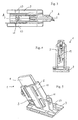
- eine Seitenansicht einer Kohlebürste,
- Fig. 2
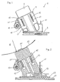
- einen Querschnitt durch die Kohlebürste von Fig. 1,
- Fig. 3
- eine Draufsicht auf die Kohlebürste,
- Fig. 4
- eine Seitenansicht auf die schmale Seite der Kohlebürste, und
- Fig. 5
- eine perspektivische Ansicht der Kohlebürste von Fig. 1.
- Fig. 1 zeigt eine Seitenansicht einer Kohlebürste 1, die als Schleifkontakt für eine Leitfähigkeitsmesseinrichtung bei einem Wäschetrockner zum Einsatz kommt. Ein Gehäuse 3 der Kohlebürste 1 umfasst eine Taschenführung 5, in die eine Schleifkohle 7 axial verschiebbar eingesetzt ist. Die Figuren 1 bis 3 und 5 zeigen die Schleifkohle 7 in ihrem maximal aus der Taschenführung 5 herausgefahrenen Position. Bei ihrer Montage wird die Kohlebürste 1 jedoch derart an ihrer Montageposition befestigt, dass die Schleifkohle 7 in die Taschenführung 5 gegen die Vorspannung von zwei Schraubenfedern 15 in die Taschenführung 5 hineingedrückt ist. Am unteren Ende weist das Gehäuse 3 eine Basis 9 auf, mit der die Kohlebürste 1 in ihrer Montageposition (siehe unten) befestigt wird.
- An der Gehäuseaußenseite ragt ein Kontakt 11 hervor, über den durch Aufstecken einer Kontaktklemme eine elektrische Verbindung zur Leitfähigkeitsmesseinrichtung herstellbar ist. Der Kontakt 11 ist über eine elektrisch leitfähige Metalllitze 13 mit dem unteren Ende der Schleifkohle 7 verbunden. Die Litze 13 ist am unteren Ende der Schleifkohle 7 eingepresst und wirkt als Rückhalteelement, das den Herausschiebeweg der Schleifkohle aus der Taschenführung 5 begrenzt. Zur Montage der Schleifkohle 7 in der Taschenführung 5 wird die Schleifkohle 7 gegen die Schraubenfedern 15 niedergedrückt bis zum unteren Anschlag. Die Litze 13 mit dem daran befestigten Kontakt 11 wird durch einen Durchgang im Gehäuse 3 geführt und der Kontakt 11 von unten in einen Schlitz eingeführt, in dem der Kontakt 11 verrastet wird, so dass der Kontakt 11 die Litze 13 im Gehäuse 3 verankert.
- An der Seite des Gehäuses 3 sind Langlöcher 17 angeordnet, durch die während der Montage der Schleifkohle 7 die korrekte Ausrichtung der Federn und der Schleifkohle 7 überprüfbar ist. Auch ist durch die Langlöcher 17 eine Kontrolle des Abnutzungsgrades der Schleifkohle 7 gewährleistet, so dass bei Fehlern in der Leitfähigkeitsmessung der Zustand der Schleifkohle 7 auf einfache Weise überprüfbar ist.
- An einer seitlichen Platte der Taschenführung 5 ist eine Blattfeder 19 gelagert, die einen Hebel 21 gegen die schmale Seite der Schleifkohle 7 vorspannt, wie dies aus der Querschnittsdarstellung in Fig. 2 ersichtlich ist. Fig. 4 zeigt eine Seitenansicht der Kohlebürste 1 von der Seite der Blattfeder 19 (von links gesehen bezüglich Fig. 1).
Der seitlich vom Hebel 21 auf die Schleifkohle 7 ausgeübte Druck dämpft die Auslenkungsbewegungen der Schleifkohle 7 während diese auf einem Schleifband 29 abläuft und verhindert so, dass aufgrund von Eigenschwingungen ein Rubbeln der Kohle entlang des Schleifbandes 29 und damit Schwingungen auftreten. Daneben wirkt die Blattfeder 19 auch zum Ausgleich des Spiels, das zwischen Schleifkohle und Taschenführung 5 vorgesehen ist, um thermische Ausdehnungsunterschiede auszugleichen. Die mit dem Umfang der Wäschetrommel in elektrischem und thermischem Kontakt stehende Schleifkohle erwärmt sich durch die Aufheizung im Trommelinneren wesentlich stärker als die Taschenführung 5. Die thermische Ausdehnung macht sich besonders in der größeren Längsausdehnung bemerkbar, so dass hier die Blattfeder 19 zusätzlich das seitliche Spiel minimiert. - Fig. 3 zeigt eine Draufsicht auf die Kohlebürste 1 und mit der Schnittlinie A-A ist die Schnittebene der Fig. 2 angedeutet. Zusätzlich zeigt Fig. 2 schematisch einen Querschnitt durch einen Sockel 25, in den die Basis 9 in seitlich gelegenen Führungsnuten des Sockels 25 eingeschoben ist. Auf der Oberseite der Basis 9 sind beidseitig Rastnasen 23 ausgebildet (Draufsicht in Fig. 3 oder perspektivische Ansicht in Fig. 5), die in seitliche Ausnehmungen in den Führungsnuten des Sockels 25 einrasten. Die Führungsnuten des Sockels 25 sind einseitig geöffnet, so dass zur Montage die Basis 9 des Gehäuses 3 in die Nuten des Sockels 25 einschiebbar sind. In der Endposition schlägt die Vorderseite der Basis 9 gegen einen Anschlag im Sockel 25 an und die Rastnasen 23 greifen in die Ausnehmungen an den Führungsnuten ein. Durch diese Rastverbindungen wird eine Schnellmontage der Kohlebürste 1 im Sockel 25 ermöglicht, der wiederum beim Montageprozess zuvor auf einem Bodenblech 27 (in Fig. 2 im Querschnitt angedeutet) montiert ist. Bei der Montage wird die Schleifkohle 7 niedergedrückt und nach dem Einrasten in den Sockel 25 losgelassen, so dass die Schleifkohle 7 nach kurzem Auslenkungsweg auf dem in Fig. 2 dargestellten Schleifband 29 anliegt. Das Schleifband ist in Fig. 2 nur angedeutet und tatsächlich wird die Schleifkohle 7 wie oben beschrieben im Neuzustand durch das Schleifband 29 bis nahezu ans untere Ende der Taschenführung 5 gedrückt, so dass lediglich ein kleiner Spalt zwischen Bodenbereich der Taschenführung 5 und der Unterkante der Schleifkohle 7 bestehen bleibt.
- Die Schleifkohle ist ungefähr 4 mm breit (die Tiefe senkrecht zur Zeichenebene wie in Fig. 1 und 2 dargestellt) und quer zur Verschiebungsachse (wie in Fig. 1 dargestellt) etwa 30 mm lang. Das in Fig. 2 angedeutete Schleifband 29 umgreift eine nicht dargestellte Wäschetrommel des Wäschetrockners und hat einen Radius von ungefähr 27 cm. Fig. 2 zeigt dabei einen Querschnitt von der Seite her gesehen und mit 31 ist ein Spalt dargestellt, der durch die Fügestelle des um die Wäschetrommel herumliegenden Bandes 29 entsteht. Durch die im Vergleich zur Breite große Längsausdehnung der Schleifkohle 7 überbrückt diese den Spalt 31, ohne dabei den elektrischen Kontakt zum Schleifband 29 zu verlieren.
-
- 1
- Kohlebürste
- 3
- Gehäuse
- 5
- Taschenführung
- 7
- Schleifkohle
- 9
- Basis
- 11
- Kontakt
- 13
- Litze
- 15
- Schraubenfeder
- 17
- Langloch
- 19
- Blattfeder
- 21
- Hebel
- 23
- Rastnase
- 25
- Sockel (Führungsnut)
- 27
- Bodenblech
- 29
- Schleifband
- 31
- Spalt
Claims (27)
- Wäschetrockner mit einer Wäschetrommel und zumindest einer die Wäschetrommel elektrisch kontaktierenden Schleifkontaktvorrichtung (1), wobei die zumindest eine Schleifkontaktvorrichtung ein Schleifelement (7) und ein Gehäuse (3) mit einer Ausnehmung (5) aufweist, wobei innerhalb der Ausnehmung (5) das Schleifelement (7) axial verschiebbar gelagert ist.
- Wäschetrockner nach Anspruch 1, wobei der Wäschetrockner eine Leitfähigkeitsmesseinrichtung aufweist, mit der über zumindest eine der Schleifkontaktvorrichtungen (1) ein Messsignal an die Wäschetrommel anlegbar oder von dieser abgreifbar ist.
- Wäschetrockner nach Anspruch 1 oder 2, wobei die Wäschetrommel eine Schleifstrecke, ein Schleifband (29) oder einen Schleifring aufweist.
- Wäschetrockner nach Anspruch 1, 2 oder 3, wobei die Verschiebungsachse des Schleifelements (7) radial oder ungefähr radial zur Wäschetrommel ausgerichtet ist.
- Wäschetrockner nach einem der vorhergehenden Ansprüche, wobei das Verhältnis der Länge zur Breite des Querschnitts der Ausnehmung (5) senkrecht zur Verschiebungsachse größer gleich 3 ist, vorteilhaft größer gleich 5 ist oder im Bereich von 3 bis 10 liegt.
- Wäschetrockner nach einem der vorhergehenden Ansprüche, wobei das Schleifelement (7) länger als breit ist, wobei insbesondere das Verhältnis der Länge zur Breite größer gleich 3 ist, vorteilhaft größer gleich 5 oder im Bereich von 3 bis 10 liegt.
- Wäschetrockner nach einem der vorhergehenden Ansprüche, wobei das Schleifelement (7) eine Schleifkohle ist.
- Wäschetrockner nach einem der vorhergehenden Ansprüche, wobei die Schleifkontaktvorrichtung (1) zumindest ein seitlich auf das Schleifelement (7) wirkendes Dämpfungselement (19) und/oder Ausdehnungskompensationselement aufweist.
- Wäschetrockner nach Anspruch 8, wobei das Dämpfungselement (19) und/oder Ausdehnungskompensationselement eine Feder ist, insbesondere eine Band- oder Blattfeder.
- Wäschetrockner nach Anspruch 8 oder 9, wobei zumindest ein Dämpfungselement (19) und/oder Ausdehnungskompensationselement auf die schmale Seite des Schleifelements (7) wirkt.
- Wäschetrockner nach einem der vorhergehenden Ansprüche, wobei zumindest ein, vorzugsweise zwei axial auf das Schleifelement (7) wirkende Federelemente (15) angeordnet sind.
- Wäschetrockner nach einem der vorhergehenden Ansprüche, wobei das Schleifelement (7) über ein Rückhalteelement (13) mit dem unteren Gehäusebereich der Schleifkontakthalterung (3) verbunden ist.
- Wäschetrockner nach Anspruch 12, wobei das Rückhalteelement (13) eine axiale Verschiebung des Schleifelements (7) zur Austrittsseite der Ausnehmung (5) begrenzt.
- Wäschetrockner nach einem der Ansprüche 8 bis 13, wobei das Rückhalteelement (13) und/oder das Dämpfungselement (19) und/oder das Ausdehnungskompensationselement elektrisch leitend ist, insbesondere das Schleifelement (7) elektrisch mit einer an der Gehäuseaußenseite angeordneten Kontaktstelle (11) verbindet.
- Wäschetrockner nach Anspruch 12, 13 oder 14, wobei das Rückhalteelement (19) biegbar ist, insbesondere eine Litze ist.
- Wäschetrockner nach einem der vorhergehenden Ansprüche, wobei die Schleifkontaktvorrichtung (1) eine Basis (9) zur Befestigung an einem Sockel (25) oder an einer Montageposition des Wäschetrockners aufweist.
- Wäschetrockner nach Anspruch 16, wobei die Basis (9) eine Führungsfläche oder Anlagefläche aufweist, die zur Verschiebungsachse des Schleifelements (7) geneigt ist.
- Wäschetrockner nach Anspruch 17, wobei die Neigung im Bereich von 5° bis 85° liegt, vorzugsweise im Bereich von 30° bis 80°, besonders bevorzugt im Bereich von 45° bis 80°.
- Wäschetrockner nach einem der vorhergehenden Ansprüche, mit einem an einer Montageposition des Wäschetrockners befestigbaren Sockel (25), wobei die Schleifkontaktvorrichtung (1) mit ihrer Basis (9) im Sockel (25) befestigbar ist, insbesondere mit ihrer Basis im Sockel einrastbar ist.
- Wäschetrockner nach Anspruch 19, wobei der Sockel (25) eine erste Ebene aufweist, die in der Ebene der Montageposition des Wäschetrockners liegt, und eine zweite Ebene aufweist, die in der Ebene der Basis (9) der Schleifkontakthalterung (1) liegt, und wobei die erste und die zweite Ebene unter einem Winkel zueinander stehen.
- Wäschetrockner nach Anspruch 20, wobei der Winkel im Bereich von 5° bis 80° liegt, vorzugsweise im Bereich von 10° bis 60°, besonders bevorzugt im Bereich von 20° bis 45°.
- Schleifkontaktvorrichtung (1) mit einem Schleifelement (7) und einer Ausnehmung (5) zur axial verschiebbaren Aufnahme des Schleifelements (7), wobei die Schleifkontaktvorrichtung (1) zumindest ein seitlich auf das Schleifelement (7) wirkendes Dämpfungselement (19) und/oder Ausdehnungskompensationselement aufweist.
- Schleifkontaktvorrichtung nach Anspruch 22, wobei das Dämpfungselement (19) und/oder Ausdehnungskompensationselement eine Feder ist, insbesondere eine Blatt- oder Bandfeder.
- Schleifkontaktvorrichtung nach Anspruch 22 oder 23, wobei zumindest ein Dämpfungselement (19) und/oder Ausdehnungskompensationselement auf die schmale Seite des Schleifelements (7) wirkt.
- Wäschetrockner nach Anspruch 22, 23 oder 24, wobei das Schleifelement (7) länger als breit ist, wobei insbesondere das Verhältnis der Länge zur Breite größer gleich 3 ist, vorteilhaft größer gleich 5 oder im Bereich von 3 bis 10 liegt.
- Schleifkontaktvorrichtung nach einem der Ansprüche 22 bis 25, wobei eine Montagebasis (9) der Schleifkontaktvorrichtung (1) eine Führungsfläche oder Anlagefläche aufweist, die zur Verschiebungsachse des Schleifelements (7) geneigt ist.
- Schleifkontaktvorrichtung nach Anspruch 26, wobei die Neigung im Bereich von 5° bis 85° liegt, vorzugsweise im Bereich von 30° bis 80°, besonders bevorzugt im Bereich von 45° bis 80°.
Priority Applications (1)
| Application Number | Priority Date | Filing Date | Title |
|---|---|---|---|
| PL06020206T PL1770201T3 (pl) | 2005-09-30 | 2006-09-27 | Urządzenie styku ruchomego i suszarka do bielizny z takim urządzeniem |
Applications Claiming Priority (1)
| Application Number | Priority Date | Filing Date | Title |
|---|---|---|---|
| DE202005015604U DE202005015604U1 (de) | 2005-09-30 | 2005-09-30 | Schleifkontaktvorrichtung und Wäschetrockner mit einer solchen |
Publications (2)
| Publication Number | Publication Date |
|---|---|
| EP1770201A1 true EP1770201A1 (de) | 2007-04-04 |
| EP1770201B1 EP1770201B1 (de) | 2009-11-11 |
Family
ID=35508572
Family Applications (1)
| Application Number | Title | Priority Date | Filing Date |
|---|---|---|---|
| EP06020206A Revoked EP1770201B1 (de) | 2005-09-30 | 2006-09-27 | Schleifkontaktvorrichtung und Wäschetrockner mit einer solchen |
Country Status (5)
| Country | Link |
|---|---|
| EP (1) | EP1770201B1 (de) |
| AT (1) | ATE448352T1 (de) |
| DE (2) | DE202005015604U1 (de) |
| ES (1) | ES2334454T3 (de) |
| PL (1) | PL1770201T3 (de) |
Cited By (2)
| Publication number | Priority date | Publication date | Assignee | Title |
|---|---|---|---|---|
| EP2028314A1 (de) | 2007-08-22 | 2009-02-25 | MIELE & CIE. KG | Wäschetrockner mit einer Haltevorrichtung |
| DE102013104118A1 (de) * | 2013-04-24 | 2014-10-30 | Miele & Cie. Kg | Taster zur Erfassung der Restfeuchte von in einer Trommel eines Wäschetrockners befindlicher Wäsche |
Families Citing this family (1)
| Publication number | Priority date | Publication date | Assignee | Title |
|---|---|---|---|---|
| IT201700103738A1 (it) * | 2017-09-15 | 2019-03-15 | Eldor Corp Spa | Gruppo porta-spazzole per una macchina elettrica a rotore eccitato |
Citations (4)
| Publication number | Priority date | Publication date | Assignee | Title |
|---|---|---|---|---|
| US3287818A (en) * | 1964-03-12 | 1966-11-29 | Whirlpool Co | Electronic dryer control pick-up device |
| US3402478A (en) * | 1966-06-20 | 1968-09-24 | Westinghouse Electric Corp | Dryer control |
| DE19737340A1 (de) * | 1997-08-27 | 1999-03-04 | Aeg Hausgeraete Gmbh | Programmgesteuerter elektrischer Wäschetrockner |
| DE102004019700B3 (de) * | 2004-04-20 | 2005-06-30 | Miele & Cie. Kg | Verfahren und Vorrichtung zur Erkennung von Betriebszuständen in einem elektronisch gesteuerten Wäschetrockner |
-
2005
- 2005-09-30 DE DE202005015604U patent/DE202005015604U1/de not_active Expired - Lifetime
-
2006
- 2006-09-27 DE DE502006005323T patent/DE502006005323D1/de active Active
- 2006-09-27 PL PL06020206T patent/PL1770201T3/pl unknown
- 2006-09-27 AT AT06020206T patent/ATE448352T1/de active
- 2006-09-27 ES ES06020206T patent/ES2334454T3/es active Active
- 2006-09-27 EP EP06020206A patent/EP1770201B1/de not_active Revoked
Patent Citations (4)
| Publication number | Priority date | Publication date | Assignee | Title |
|---|---|---|---|---|
| US3287818A (en) * | 1964-03-12 | 1966-11-29 | Whirlpool Co | Electronic dryer control pick-up device |
| US3402478A (en) * | 1966-06-20 | 1968-09-24 | Westinghouse Electric Corp | Dryer control |
| DE19737340A1 (de) * | 1997-08-27 | 1999-03-04 | Aeg Hausgeraete Gmbh | Programmgesteuerter elektrischer Wäschetrockner |
| DE102004019700B3 (de) * | 2004-04-20 | 2005-06-30 | Miele & Cie. Kg | Verfahren und Vorrichtung zur Erkennung von Betriebszuständen in einem elektronisch gesteuerten Wäschetrockner |
Cited By (4)
| Publication number | Priority date | Publication date | Assignee | Title |
|---|---|---|---|---|
| EP2028314A1 (de) | 2007-08-22 | 2009-02-25 | MIELE & CIE. KG | Wäschetrockner mit einer Haltevorrichtung |
| DE102007039707A1 (de) | 2007-08-22 | 2009-07-30 | Miele & Cie. Kg | Wäschetrockner mit einer Haltevorrichtung |
| US8042285B2 (en) | 2007-08-22 | 2011-10-25 | Miele & Cie. Kg | Laundry dryer with a holding device |
| DE102013104118A1 (de) * | 2013-04-24 | 2014-10-30 | Miele & Cie. Kg | Taster zur Erfassung der Restfeuchte von in einer Trommel eines Wäschetrockners befindlicher Wäsche |
Also Published As
| Publication number | Publication date |
|---|---|
| DE202005015604U1 (de) | 2005-12-15 |
| EP1770201B1 (de) | 2009-11-11 |
| ES2334454T3 (es) | 2010-03-10 |
| ATE448352T1 (de) | 2009-11-15 |
| PL1770201T3 (pl) | 2010-04-30 |
| DE502006005323D1 (de) | 2009-12-24 |
Similar Documents
| Publication | Publication Date | Title |
|---|---|---|
| DE69414687T2 (de) | Drehender elektrischer Schleifring mit Mehrdrahtbürsten | |
| WO2014040670A1 (de) | Kontaktelement | |
| DE102019116064A1 (de) | Königszapfenanordnung | |
| EP1770201B1 (de) | Schleifkontaktvorrichtung und Wäschetrockner mit einer solchen | |
| EP1711985B1 (de) | Bürstenköcher für eine Dynamo-elektrische Maschine | |
| EP2409386B1 (de) | Elektrischer antriebsmotor, insbesondere für ein aggregat in einem kraftfahrzeug | |
| DE102021004953B3 (de) | Steckverbinder und Gegensteckverbinder | |
| EP2028314B1 (de) | Wäschetrockner mit einer Haltevorrichtung | |
| EP1481462B1 (de) | Elektromotor | |
| EP1537635B1 (de) | Bürste für eine dynamo-elektrische maschine | |
| DE102018200195B4 (de) | Antrieb mit einem kommutatormotor | |
| WO2000045474A1 (de) | Kohlebürste | |
| DE69302356T2 (de) | Elektrodynamische Maschine mit Blechbügelbürsten | |
| EP1045661B1 (de) | Staubsauger | |
| DE19815488C1 (de) | Elektrischer Steckverbinder | |
| EP1206005A1 (de) | Crimpkontakt für Leiterplatten | |
| DE10216491C1 (de) | Steckverbinder mit Schneidklemmkontakten | |
| DE19825630C1 (de) | Verbindungsklemme | |
| EP1626479B1 (de) | Kohlebürstenhalteranordnung | |
| EP3561173B1 (de) | Abtaster für eine einrichtung zur erfassung eines feuchtegehalts einer wäsche, einrichtung und wäschetrockner | |
| EP0131105B1 (de) | Drehkupplung für Mehrleiterkabel | |
| DE19523899B4 (de) | Mechanisch kommutierter Elektromotor | |
| DE19755719C2 (de) | Kontakt einer Lötverbindung | |
| DE2722696C2 (de) | Anschluß- und Klemmeinrichtung für Koaxialkabel, insbesondere für Antennensteckdosen | |
| DE102008019634B4 (de) | Steckverbindersystem mit Sekundärverriegelung |
Legal Events
| Date | Code | Title | Description |
|---|---|---|---|
| PUAI | Public reference made under article 153(3) epc to a published international application that has entered the european phase |
Free format text: ORIGINAL CODE: 0009012 |
|
| AK | Designated contracting states |
Kind code of ref document: A1 Designated state(s): AT BE BG CH CY CZ DE DK EE ES FI FR GB GR HU IE IS IT LI LT LU LV MC NL PL PT RO SE SI SK TR |
|
| AX | Request for extension of the european patent |
Extension state: AL BA HR MK YU |
|
| 17P | Request for examination filed |
Effective date: 20070926 |
|
| 17Q | First examination report despatched |
Effective date: 20071025 |
|
| AKX | Designation fees paid |
Designated state(s): AT BE BG CH CY CZ DE DK EE ES FI FR GB GR HU IE IS IT LI LT LU LV MC NL PL PT RO SE SI SK TR |
|
| GRAP | Despatch of communication of intention to grant a patent |
Free format text: ORIGINAL CODE: EPIDOSNIGR1 |
|
| GRAS | Grant fee paid |
Free format text: ORIGINAL CODE: EPIDOSNIGR3 |
|
| GRAA | (expected) grant |
Free format text: ORIGINAL CODE: 0009210 |
|
| AK | Designated contracting states |
Kind code of ref document: B1 Designated state(s): AT BE BG CH CY CZ DE DK EE ES FI FR GB GR HU IE IS IT LI LT LU LV MC NL PL PT RO SE SI SK TR |
|
| REG | Reference to a national code |
Ref country code: GB Ref legal event code: FG4D Free format text: NOT ENGLISH |
|
| REG | Reference to a national code |
Ref country code: CH Ref legal event code: EP |
|
| REG | Reference to a national code |
Ref country code: IE Ref legal event code: FG4D |
|
| REF | Corresponds to: |
Ref document number: 502006005323 Country of ref document: DE Date of ref document: 20091224 Kind code of ref document: P |
|
| REG | Reference to a national code |
Ref country code: ES Ref legal event code: FG2A Ref document number: 2334454 Country of ref document: ES Kind code of ref document: T3 |
|
| NLV1 | Nl: lapsed or annulled due to failure to fulfill the requirements of art. 29p and 29m of the patents act | ||
| LTIE | Lt: invalidation of european patent or patent extension |
Effective date: 20091111 |
|
| PG25 | Lapsed in a contracting state [announced via postgrant information from national office to epo] |
Ref country code: IS Free format text: LAPSE BECAUSE OF FAILURE TO SUBMIT A TRANSLATION OF THE DESCRIPTION OR TO PAY THE FEE WITHIN THE PRESCRIBED TIME-LIMIT Effective date: 20100311 Ref country code: SE Free format text: LAPSE BECAUSE OF FAILURE TO SUBMIT A TRANSLATION OF THE DESCRIPTION OR TO PAY THE FEE WITHIN THE PRESCRIBED TIME-LIMIT Effective date: 20091111 Ref country code: LT Free format text: LAPSE BECAUSE OF FAILURE TO SUBMIT A TRANSLATION OF THE DESCRIPTION OR TO PAY THE FEE WITHIN THE PRESCRIBED TIME-LIMIT Effective date: 20091111 Ref country code: FI Free format text: LAPSE BECAUSE OF FAILURE TO SUBMIT A TRANSLATION OF THE DESCRIPTION OR TO PAY THE FEE WITHIN THE PRESCRIBED TIME-LIMIT Effective date: 20091111 Ref country code: PT Free format text: LAPSE BECAUSE OF FAILURE TO SUBMIT A TRANSLATION OF THE DESCRIPTION OR TO PAY THE FEE WITHIN THE PRESCRIBED TIME-LIMIT Effective date: 20100311 |
|
| REG | Reference to a national code |
Ref country code: PL Ref legal event code: T3 |
|
| PG25 | Lapsed in a contracting state [announced via postgrant information from national office to epo] |
Ref country code: CY Free format text: LAPSE BECAUSE OF FAILURE TO SUBMIT A TRANSLATION OF THE DESCRIPTION OR TO PAY THE FEE WITHIN THE PRESCRIBED TIME-LIMIT Effective date: 20091111 Ref country code: SI Free format text: LAPSE BECAUSE OF FAILURE TO SUBMIT A TRANSLATION OF THE DESCRIPTION OR TO PAY THE FEE WITHIN THE PRESCRIBED TIME-LIMIT Effective date: 20091111 Ref country code: LV Free format text: LAPSE BECAUSE OF FAILURE TO SUBMIT A TRANSLATION OF THE DESCRIPTION OR TO PAY THE FEE WITHIN THE PRESCRIBED TIME-LIMIT Effective date: 20091111 |
|
| REG | Reference to a national code |
Ref country code: IE Ref legal event code: FD4D |
|
| PG25 | Lapsed in a contracting state [announced via postgrant information from national office to epo] |
Ref country code: RO Free format text: LAPSE BECAUSE OF FAILURE TO SUBMIT A TRANSLATION OF THE DESCRIPTION OR TO PAY THE FEE WITHIN THE PRESCRIBED TIME-LIMIT Effective date: 20091111 Ref country code: EE Free format text: LAPSE BECAUSE OF FAILURE TO SUBMIT A TRANSLATION OF THE DESCRIPTION OR TO PAY THE FEE WITHIN THE PRESCRIBED TIME-LIMIT Effective date: 20091111 Ref country code: DK Free format text: LAPSE BECAUSE OF FAILURE TO SUBMIT A TRANSLATION OF THE DESCRIPTION OR TO PAY THE FEE WITHIN THE PRESCRIBED TIME-LIMIT Effective date: 20091111 Ref country code: IE Free format text: LAPSE BECAUSE OF FAILURE TO SUBMIT A TRANSLATION OF THE DESCRIPTION OR TO PAY THE FEE WITHIN THE PRESCRIBED TIME-LIMIT Effective date: 20091111 Ref country code: BG Free format text: LAPSE BECAUSE OF FAILURE TO SUBMIT A TRANSLATION OF THE DESCRIPTION OR TO PAY THE FEE WITHIN THE PRESCRIBED TIME-LIMIT Effective date: 20100211 |
|
| PLBI | Opposition filed |
Free format text: ORIGINAL CODE: 0009260 |
|
| PG25 | Lapsed in a contracting state [announced via postgrant information from national office to epo] |
Ref country code: SK Free format text: LAPSE BECAUSE OF FAILURE TO SUBMIT A TRANSLATION OF THE DESCRIPTION OR TO PAY THE FEE WITHIN THE PRESCRIBED TIME-LIMIT Effective date: 20091111 Ref country code: CZ Free format text: LAPSE BECAUSE OF FAILURE TO SUBMIT A TRANSLATION OF THE DESCRIPTION OR TO PAY THE FEE WITHIN THE PRESCRIBED TIME-LIMIT Effective date: 20091111 |
|
| PLAX | Notice of opposition and request to file observation + time limit sent |
Free format text: ORIGINAL CODE: EPIDOSNOBS2 |
|
| 26 | Opposition filed |
Opponent name: SCHUNK MODULTECHNIK GMBH Effective date: 20100805 |
|
| PG25 | Lapsed in a contracting state [announced via postgrant information from national office to epo] |
Ref country code: GR Free format text: LAPSE BECAUSE OF FAILURE TO SUBMIT A TRANSLATION OF THE DESCRIPTION OR TO PAY THE FEE WITHIN THE PRESCRIBED TIME-LIMIT Effective date: 20100212 |
|
| PLBB | Reply of patent proprietor to notice(s) of opposition received |
Free format text: ORIGINAL CODE: EPIDOSNOBS3 |
|
| RAP2 | Party data changed (patent owner data changed or rights of a patent transferred) |
Owner name: ELECTROLUX HOME PRODUCTS CORPORATION N.V. |
|
| BERE | Be: lapsed |
Owner name: ELECTROLUX HOME PRODUCTS CORPORATION N.V. Effective date: 20100930 |
|
| PG25 | Lapsed in a contracting state [announced via postgrant information from national office to epo] |
Ref country code: MC Free format text: LAPSE BECAUSE OF NON-PAYMENT OF DUE FEES Effective date: 20100930 |
|
| REG | Reference to a national code |
Ref country code: CH Ref legal event code: PL |
|
| RAP2 | Party data changed (patent owner data changed or rights of a patent transferred) |
Owner name: ELECTROLUX HOME PRODUCTS CORPORATION N.V. |
|
| PG25 | Lapsed in a contracting state [announced via postgrant information from national office to epo] |
Ref country code: BE Free format text: LAPSE BECAUSE OF NON-PAYMENT OF DUE FEES Effective date: 20100930 Ref country code: LI Free format text: LAPSE BECAUSE OF NON-PAYMENT OF DUE FEES Effective date: 20100930 Ref country code: CH Free format text: LAPSE BECAUSE OF NON-PAYMENT OF DUE FEES Effective date: 20100930 |
|
| PLAY | Examination report in opposition despatched + time limit |
Free format text: ORIGINAL CODE: EPIDOSNORE2 |
|
| REG | Reference to a national code |
Ref country code: FR Ref legal event code: CA Effective date: 20120116 |
|
| PG25 | Lapsed in a contracting state [announced via postgrant information from national office to epo] |
Ref country code: NL Free format text: LAPSE BECAUSE OF FAILURE TO SUBMIT A TRANSLATION OF THE DESCRIPTION OR TO PAY THE FEE WITHIN THE PRESCRIBED TIME-LIMIT Effective date: 20091111 Ref country code: LU Free format text: LAPSE BECAUSE OF NON-PAYMENT OF DUE FEES Effective date: 20100927 Ref country code: HU Free format text: LAPSE BECAUSE OF FAILURE TO SUBMIT A TRANSLATION OF THE DESCRIPTION OR TO PAY THE FEE WITHIN THE PRESCRIBED TIME-LIMIT Effective date: 20100512 |
|
| PG25 | Lapsed in a contracting state [announced via postgrant information from national office to epo] |
Ref country code: TR Free format text: LAPSE BECAUSE OF FAILURE TO SUBMIT A TRANSLATION OF THE DESCRIPTION OR TO PAY THE FEE WITHIN THE PRESCRIBED TIME-LIMIT Effective date: 20091111 |
|
| REG | Reference to a national code |
Ref country code: AT Ref legal event code: MM01 Ref document number: 448352 Country of ref document: AT Kind code of ref document: T Effective date: 20110927 |
|
| PG25 | Lapsed in a contracting state [announced via postgrant information from national office to epo] |
Ref country code: AT Free format text: LAPSE BECAUSE OF NON-PAYMENT OF DUE FEES Effective date: 20110927 |
|
| RDAF | Communication despatched that patent is revoked |
Free format text: ORIGINAL CODE: EPIDOSNREV1 |
|
| REG | Reference to a national code |
Ref country code: DE Ref legal event code: R064 Ref document number: 502006005323 Country of ref document: DE Ref country code: DE Ref legal event code: R103 Ref document number: 502006005323 Country of ref document: DE |
|
| PGFP | Annual fee paid to national office [announced via postgrant information from national office to epo] |
Ref country code: DE Payment date: 20130919 Year of fee payment: 8 Ref country code: ES Payment date: 20130927 Year of fee payment: 8 |
|
| PGFP | Annual fee paid to national office [announced via postgrant information from national office to epo] |
Ref country code: FR Payment date: 20130919 Year of fee payment: 8 Ref country code: PL Payment date: 20130822 Year of fee payment: 8 Ref country code: GB Payment date: 20130919 Year of fee payment: 8 |
|
| PGFP | Annual fee paid to national office [announced via postgrant information from national office to epo] |
Ref country code: IT Payment date: 20130925 Year of fee payment: 8 |
|
| RDAG | Patent revoked |
Free format text: ORIGINAL CODE: 0009271 |
|
| STAA | Information on the status of an ep patent application or granted ep patent |
Free format text: STATUS: PATENT REVOKED |
|
| 27W | Patent revoked |
Effective date: 20131006 |
|
| GBPR | Gb: patent revoked under art. 102 of the ep convention designating the uk as contracting state |
Effective date: 20131006 |
|
| REG | Reference to a national code |
Ref country code: DE Ref legal event code: R107 Ref document number: 502006005323 Country of ref document: DE Effective date: 20140320 |
|
| REG | Reference to a national code |
Ref country code: AT Ref legal event code: MA03 Ref document number: 448352 Country of ref document: AT Kind code of ref document: T Effective date: 20131006 |