EP1770021B1 - Plastic closure - Google Patents
Plastic closure Download PDFInfo
- Publication number
- EP1770021B1 EP1770021B1 EP06254476A EP06254476A EP1770021B1 EP 1770021 B1 EP1770021 B1 EP 1770021B1 EP 06254476 A EP06254476 A EP 06254476A EP 06254476 A EP06254476 A EP 06254476A EP 1770021 B1 EP1770021 B1 EP 1770021B1
- Authority
- EP
- European Patent Office
- Prior art keywords
- cavity
- cap
- closure
- orifice
- stopping
- Prior art date
- Legal status (The legal status is an assumption and is not a legal conclusion. Google has not performed a legal analysis and makes no representation as to the accuracy of the status listed.)
- Not-in-force
Links
Images


Classifications
-
- B—PERFORMING OPERATIONS; TRANSPORTING
- B65—CONVEYING; PACKING; STORING; HANDLING THIN OR FILAMENTARY MATERIAL
- B65D—CONTAINERS FOR STORAGE OR TRANSPORT OF ARTICLES OR MATERIALS, e.g. BAGS, BARRELS, BOTTLES, BOXES, CANS, CARTONS, CRATES, DRUMS, JARS, TANKS, HOPPERS, FORWARDING CONTAINERS; ACCESSORIES, CLOSURES, OR FITTINGS THEREFOR; PACKAGING ELEMENTS; PACKAGES
- B65D47/00—Closures with filling and discharging, or with discharging, devices
- B65D47/04—Closures with discharging devices other than pumps
- B65D47/06—Closures with discharging devices other than pumps with pouring spouts or tubes; with discharge nozzles or passages
- B65D47/08—Closures with discharging devices other than pumps with pouring spouts or tubes; with discharge nozzles or passages having articulated or hinged closures
- B65D47/0804—Closures with discharging devices other than pumps with pouring spouts or tubes; with discharge nozzles or passages having articulated or hinged closures integrally formed with the base element provided with the spout or discharge passage
- B65D47/0833—Hinges without elastic bias
- B65D47/0838—Hinges without elastic bias located at an edge of the base element
Definitions
- the present invention relates to a cap of synthetic material including an orifice and a stopping device integrated with this orifice, and also to an assembly including a container and such a cap.
- the cap according to the invention is more specifically intended to equip containers containing pasty products such as toiletries (shampoo, shower gel, etc.) or cosmetic products (creams, etc.), without these applications being limiting.
- caps used in particular in the aforementioned domains are already known.
- these caps include a body mounted on a container provided with an opening; this body includes both an end wall provided with an orifice placed opposite the container's opening and also a lateral skirt.
- a stopping device for the body's orifice which can be moved between a closed position where the orifice is stopped, and an open position where the orifice is cleared and allows the flow of the product out of the container, is also provided.
- DE-U-79 18 747 describes a closure as set out in the preamble of Claim 1.
- the user is obligated to manoeuvre the opening device by placing their fingers in the area of the outlet orifice which results in increased risks of slipping and possible hygiene problems, even contamination of the container's contents.
- An opening is obtained whose flow is too weak, and does not allow a significant outlet flow-rate for the product.
- the present invention aims to remedy the disadvantages mentioned above by providing a cap having a stopping device that is simple to manoeuvre for both opening and closing.
- a container closure comprising a body which is mountable on a container and includes a skirt closed at one end by an end wall provided with an orifice; the end wall having a cavity and a stop between the cavity and the orifice; a stop member including a stopping part positioned to stop the orifice and an actuating part positioned over the cavity; the actuating part having a first end articulated to the body and a second end connected to the stopping part by a hinge; the stopper member being movable between a closed position in which the stopping part stops the orifice and the actuating part is spaced from the bottom of the cavity, and an open position in which the actuating part is pressed into the cavity and to the stopping part is lifted away from the orifice by causing it to be pressed against the stop and pivot about the hinge.
- the hinge may be positioned at a distance (d1) from the stop on the cavity side.
- the position of the hinge in the stopper member may be such that it is positioned over the cavity.
- the movement of the stopper member to the open position may include a component of movement which is substantially transverse the main axis of the closure. This could allow the stopper member to slide outwards away from the stop.
- the cavity may be of generally parallelepiped shape, having a bottom and two parallel side walls.
- the cavity may open in part into the skirt and the means of articulation of the actuating part to the body may be located away from the end wall.
- the stopping part In the open position the stopping part may be wedged against the stop.
- the present invention may comprise a cap of synthetic material that has: a tubular body which is intended to be mounted on a container on the side of its opening and which includes a lateral skirt having an axis, and whose end is closed by an end wall provided with an orifice arranged to be placed opposite the opening of the container; and a stopper member integrated with said orifice.
- the body includes both a cavity in the general shape of a parallelepiped, formed in the outer wall towards the cap's inside, away from the orifice, said cavity having a bottom and two largely mutually parallel sidewalls, and also a stop placed between the cavity and the orifice projecting relative to the bottom of the cavity, mainly transversely to the cavity's lateral walls; and the stopper member includes both a stopping part suitable to stop the orifice and also an actuating part placed opposite the cavity and having a first end linked to the cap's body largely perpendicularly to the cavity's lateral walls by means of articulation, and a second end linked to the stopping part by a hinge largely perpendicular to the lateral faces, such hinge being located away from the stop on the cavity side; the stopping device can be moved between: a closed position, in which the actuating part is located away from the bottom of the cavity and the stopper member stops the orifice; and an open position, in which the actuating part has been moved relative to the
- the actuating part may be made of a rigid material.
- the actuating part Since the actuating part is made of a rigid material and does not have large dimensions, it cannot undergo significant deformation when the stopper member changes from the closed to open position. Therefore it is the "recoil" movement relative to the stop, which is made possible by the hinges, that makes this movement and therefore the clearing of the orifice possible.
- the cavity opens in part into the lateral skirt and the means of articulation of the actuating part on the cap's body are located away from the end wall.
- the actuating part can be an L-shaped pad having a first portion linked to the articulation means and arranged largely perpendicularly to the lateral walls and the bottom of the cavity when the stopper member is in closed position, and a second portion largely perpendicular to the first.
- the articulation means are therefore withdrawn, towards the inside of the cap relative to the outer wall.
- the position of the stop along with the dimensions and materials making up the articulation means and the parts making up the stopper member are arranged to allow in open position a wedging of the stopping part against the stop by placing the articulation means under tension. This way, the stopping device can be kept stably in open position without specific action by the user.
- the stopper member when it is in closed position, the stopper member can largely blend in with the continuity of the end wall and the lateral skirt of the cap. This way the cap can have a regular visible contour, free of very recessed parts or parts which project significantly.
- the stopper member could all the same be slightly hollowed or slightly projecting relative to the cap's body.
- the means of articulation of the actuating part on the cap's body can include at least one band of flexible material and/or at least one band of rigid material whose first end is bound by a first flexible zone to the cap's body and whose second end is bound by a second flexible zone to the actuating part, with said flexible zones being largely parallel to each other and orthogonal to the cavity's lateral faces.
- the lateral skirt has a curved shape in the area of the articulation means, and the articulation means include two bands largely parallel to the axis of the cap when the stopping device is in closed position, with said bands being separated from each other orthogonally to the lateral faces of the cavity.
- the lateral skirt has a largely planar shape in the area of the articulation means, and the articulation means include a band that is largely straight and orthogonal to the lateral faces of the cavity.
- the stopper member may include a flap whose thickness is less than or roughly equal to the height of the articulation means, between the cap's body and the actuating part.
- the cap includes a small bar projecting from the bottom of the cavity and whose face turned towards the cavity forms the stop.
- the cap includes a shoulder having a face perpendicular to the axis of the cap in which the orifice is placed, and a face parallel to the axis of the cap, turned towards the cavity and forming the stop.
- the invention also relates to an assembly including both the container with un opening and also a cap as previously described.
- Figures to 4 show a closure cap 1 with an axis 2.
- the cap 1 includes an end plate or wall 3 largely flat and disk-shaped.
- a generally cylindrical skirt 4 depends from the periphery of the wall 3.
- the cap 1 is mounted on a container 5, here a flexible tube containing for example a pasty, cream-type product.
- the attachment of the cap 1 on the container 5 is obtained by known means (screwing, latching, etc.).
- the container 5 includes a collar 6 whose axis is largely coincident with the axis 2 of the cap 1 in the assembled state (see Figure 6 ).
- the cap 1 includes a cavity 7 for which room is made from the end wall 3 towards the container 5.
- the cavity 7 is limited by two lateral faces 8 perpendicular to the end wall 3 and mutually parallel, a face referred to as "front” 9 perpendicular to the lateral faces 8, and a bottom 10.
- the front face 9 could be curved, for example bulging towards the cavity 7.
- the cavity 7 does not have a "rear" face, but opens into the lateral skirt 4 by locally interrupting it. In the area of this local interruption of the lateral skirt 4, the cavity 7 can include a zone 11 recessed towards the container 5 as compared to the bottom 10, thereby forming a step.
- the cavity 7 thus extends from the lateral skirt 4 over about half the diameter of the cap 1, and is further largely centred laterally relative to the transverse wall 3.
- the width of the cavity 7, meaning the distance between the lateral faces 8, is on the order of 2 to 3 cm (roughly the width of a thumb).
- the lateral faces 8 extend beyond the front face 9 up to an end face 12 generally perpendicular to said lateral faces 8.
- the end face 12 is slightly curved.
- a wall 13 largely parallel to the end wall 3 connects the end face 12 to the front face 9.
- the wall 13 is recessed towards the container 5 as compared to the end wall 3.
- the wall 13 is located axially between the end wall 3 and the bottom 10 of the cavity 7.
- the orifice 14 has dimensions smaller than that of the collar 6, and its axis 15 is largely parallel to the axis 2 of the cap 1, while also being offset from it.
- Means of sealing between the cap 1 and the container 5 are provided. As shown in Figure 6 , these means can consist of an inner skirt 16 extending below the orifice 14 towards the container 5 and intended to cooperate with the inner face of the collar 6.
- the cap 1 includes an integrated stopper member 17, linked to the lateral skirt 4, which in closed position allows stopping of the orifice 14 and which can be moved towards an open position in which the orifice 14 is cleared.
- the body of the cap 1 (end wall 3 and lateral skirt 4) and the stopping device 17 are made of a single part by moulding plastic. The stopping device 17 is described in its closed position ( Figure 1 ).
- the member 17 includes an actuating part 18 in the shape of an L-shaped tab.
- the actuating part 18 includes a first part 19 placed in the local interruption of the lateral skirt 4 for which room is made by the cavity 7, and forms with the lateral skirt 4 a largely continuous and cylindrical surface.
- a first end 20 of the first portion 19, which is largely orthogonal to the axis 2, is joined to the lateral skirt 4 by two bands 21 which are oriented largely parallel to the axis 2 and separated from each other along said first end 20.
- the bands 21 have a relatively small thickness which makes them flexible.
- the zone included between the two bands 21 may or may not be connected to the lateral skirt 4.
- the two bands 21 could be replaced by another type of connection, for example a thin film.
- the second end 22 of the first portion 19 is located largely in the plane of the end wall 3 of the cap 1.
- the actuating part 18 further includes a second portion 23 extending from the second end 22 of the first portion 19, opposite the cavity 7 and largely parallel to the end wall 3 and extending it.
- the lateral walls 24 of the second portion 23 (oriented largely perpendicular to the first portion 19) are each located near a lateral face 8 of the cavity 7.
- the second portion 23 extends up to a line forming the second end 25 of the actuating part 19 which is largely parallel to the second end 22 of the first portion 19.
- the second end 25 is located away from the front face 9 on the cavity 7 side.
- an imprint 26 is arranged in the second portion 23 to receive the user's finger.
- the member 17 further includes a stopping part 27 formed from a flap extending from the second end 25 of the actuating part 18, largely parallel to the end wall 3.
- the thickness of the flap is here roughly equal to the distance between the end of the front face 9 opposite the bottom 10 of the cavity 7 and the end wall 3.
- the stopping part 27 extends up to its free end 28, located near the end face 12 and having a shape complementary to it.
- the lateral edges 29 of the stopping part 27 extend as an extension of the lateral edges 24 of the second portion 23 of the actuating part 18.
- the stopping part 27 furthermore includes a tip 30 projecting towards the inside of the cap 1, and intended to mate with and seal the orifice 14, in the closed position.
- the stopping part 27 is linked to the actuating part 18 by a hinge 31 formed of a very narrow thin-film extending parallel to the second end 25 of the actuating part 18.
- the stopping device 17 fills the hollows formed in the end wall 3 and the lateral skirt 4 with the cap 1 thus having a visible shape which is largely cylindrical limited by a transverse wall that is flat overall.
- the stopping device 17 might not be placed exactly continuously with the body of the cap 1, but be slightly depressed or slightly projecting.
- the material used and the thickness chosen make the actuating part 18 and the stopping part 27 rigid and largely undeformable (in the case of normal use by a person).
- the second embodiment of the cap 1 according to the invention is shown in Figure 5 .
- the cap 1 from Figure 5 generally has the same features as those previously described, with the following differences.
- the cap 1 has a parallelepiped shape, the end wall 3 is predominantly square, and the lateral skirt 4 has four planar faces.
- the first portion 19 of the actuating part 18 has a first end 20 which is largely straight and connected to the lateral skirt 4 by articulation means made up of a rigid central band 32, a first flexible zone 33 placed to one side of the rigid band 32 and connected to the lateral skirt 4, and a second flexible zone 34 placed on the opposite side of the rigid band 32 and linked to the first end 20.
- articulation means made up of a rigid central band 32, a first flexible zone 33 placed to one side of the rigid band 32 and connected to the lateral skirt 4, and a second flexible zone 34 placed on the opposite side of the rigid band 32 and linked to the first end 20.
- These different elements are largely linear and oriented parallel to the first end 20. They are made up of the same material, with the central band 32 being thicker, which gives it its rigidity.
- the wall 13 is located largely in the same axial area as the bottom 10 of the cavity 7.
- a small bar 35 is defined which projects from the bottom 9 towards the end wall 3, between the orifice 14 and the cavity 7, where a space exists between the free end of the small bar 35 and the end wall 3.
- the orifice 14 is surrounded by a duct 36 extending in the direction of the end wall 3 and instead of the tip 30 the stopping part 27 has a seal skirt 37 intended to mate with the outside of the duct 36 in closed position.
- At least one rib 38 projects from the stopping part 27 towards the inside of the cap 1, in closed position.
- the ribs 38 rest on the small bar 35, the thickness e of the flap being suited for said flap to be located largely in the same plane as the end wall 3.
- the ribs 38 mate with the front face 9 of the cavity 7. They thus make it possible to place the means of articulation of the stopping device 17 under tension on the body of the cap 1 and, consequently, to assure the locking of the stopping part 27 in open position, Relative to the implementation of Figures 1 to 4 , the ribs make it possible to obtain this locking with a reduced thickness e resulting in a savings of material.
- the actuating part 18 could include means laid out on the inside face of the actuating part 18 (tabs, curved shape, etc.) which, since they are intended to mate with a guiding ramp laid out in the cavity 7 by sliding, would make it possible to ease the passage of the stopper member 17 from the closed to open position (as will be seen farther on), by limiting the rubbing surface.
- the guiding ramp could notably be made up by the shoulder between the cavity 7 and the zone 11.
- the free end 28 of the stopping part 27 is not curved but largely linear.
- the stopping part 27 rests on the small bar 35 (or the wall 13 in the case of the first embodiment), the orifice 14 being stopped through the seal skirt 37 (or the tip 38).
- the second portion 23 of the actuating part 18 is located largely in the same plane as the stopping part 27 and is kept in this position notably because of the mating between the seal skirt 37 (or tip 30) and the orifice 14, and by the tension exerted on the articulation means.
- Depressing the actuating part 18 in the cavity 7 drives the pivoting of the stopping part 27 around the hinge 31 by the pushing exerted on the small bar 35 (or the edge between the front wall 9 and the wall 13).
- the front face 9 thus forms a stop.
- This pivoting is made possible because the hinge 31 is located at a sufficient distance d1 from the front face 9 of the side of the cavity 7.
- the actuating part 18 moves down into the cavity 7, the second end 25 approaches the front face 9, the stopping part 27 slides along the front face 9 tilting more and more relative to the end wall 3 of the cap 1, and the articulation means (band 32 and flexible zones 33 and 34) approach a plane orthogonal to the axis 2 of the cap 1.
- the actuating part 18 is mainly lodged in the cavity 7, since a second portion 23 is stopped against the bottom 10, which stopped the lowering movement.
- the actuating part 18 recoiled a distance d2, less than or equal to the height of the articulation means (meaning their axial dimension considered when the stopper member 17 is in closed position).
- the stopping part 27 is largely parallel to the front face 9 and to its contact, since the orifice 14 is thus cleared and allows the distribution of the product contained in the container 5.
- the thickness e of the stopping part 27 ( Figures 1 to 4 ) or the thickness e increased by the thickness of the ribs 38 ( Figure 5 ), the distance d1 between the hinge 31 and the front face 9, the recoil distance d2 of the actuating part 18 and the height of the articulation means are intended so that, in open position, the stopping part 27 is maintained stopped against the front face 9 by the tension of the articulation means.
- d1 is less than d2.
- the invention brings a decisive improvement to the prior art, by providing a stopping device that can be very easily opened by a simple push exerted with the finger, leading to a significant clearing of the outlet orifice and to staying in open position without action by the user.
- the invention is not limited to the embodiments described above as examples, but rather encompasses all implementation variants.
- the stopping device could have larger dimensions; the end wall of the cap would then have very reduced dimensions or even be nonexistent.
Abstract
Description
- The present invention relates to a cap of synthetic material including an orifice and a stopping device integrated with this orifice, and also to an assembly including a container and such a cap.
- The cap according to the invention is more specifically intended to equip containers containing pasty products such as toiletries (shampoo, shower gel, etc.) or cosmetic products (creams, etc.), without these applications being limiting.
- Various caps used in particular in the aforementioned domains are already known. Generally these caps include a body mounted on a container provided with an opening; this body includes both an end wall provided with an orifice placed opposite the container's opening and also a lateral skirt. A stopping device for the body's orifice, which can be moved between a closed position where the orifice is stopped, and an open position where the orifice is cleared and allows the flow of the product out of the container, is also provided.
- Among the known stopping devices, the following can be cited:
- cover parts connected to the cap's body so that they pivot on a hinge;
- "push pull"-type devices in which a sliding element is moved axially around a chimney circling the orifice;
- devices made up of a disk swinging around a diametrical axis under the effect of pressure from a user's finger; and
- stoppers pivoting around a flexible zone and in which a flow channel is integrated.
-
DE-U-79 18 747 describes a closure as set out in the preamble ofClaim 1. - These different devices are not entirely satisfactory because they have one or more of the following disadvantages:
- It is difficult to manoeuvre the opening device because it does not provide a sufficient grip for the fingers, but often only enough for a fingernail, and because opening is only possible by applying a relatively significant force. This problem is even more critical should the user have wet fingers (in the shower in particular) which are therefore slippery.
- It requires following the opening movement on a significant path, which can exceed 90°.
- The user is obligated to manoeuvre the opening device by placing their fingers in the area of the outlet orifice which results in increased risks of slipping and possible hygiene problems, even contamination of the container's contents.
- An opening is obtained whose flow is too weak, and does not allow a significant outlet flow-rate for the product.
- The present invention aims to remedy the disadvantages mentioned above by providing a cap having a stopping device that is simple to manoeuvre for both opening and closing.
- According to the present invention there is provided a container closure comprising a body which is mountable on a container and includes a skirt closed at one end by an end wall provided with an orifice; the end wall having a cavity and a stop between the cavity and the orifice; a stop member including a stopping part positioned to stop the orifice and an actuating part positioned over the cavity; the actuating part having a first end articulated to the body and a second end connected to the stopping part by a hinge; the stopper member being movable between a closed position in which the stopping part stops the orifice and the actuating part is spaced from the bottom of the cavity, and an open position in which the actuating part is pressed into the cavity and to the stopping part is lifted away from the orifice by causing it to be pressed against the stop and pivot about the hinge.
- The hinge may be positioned at a distance (d1) from the stop on the cavity side. In other words, the position of the hinge in the stopper member may be such that it is positioned over the cavity.
- The movement of the stopper member to the open position may include a component of movement which is substantially transverse the main axis of the closure. This could allow the stopper member to slide outwards away from the stop.
- The cavity may be of generally parallelepiped shape, having a bottom and two parallel side walls.
- The cavity may open in part into the skirt and the means of articulation of the actuating part to the body may be located away from the end wall.
- In the open position the stopping part may be wedged against the stop.
- The present invention may comprise a cap of synthetic material that has: a tubular body which is intended to be mounted on a container on the side of its opening and which includes a lateral skirt having an axis, and whose end is closed by an end wall provided with an orifice arranged to be placed opposite the opening of the container; and a stopper member integrated with said orifice. The body includes both a cavity in the general shape of a parallelepiped, formed in the outer wall towards the cap's inside, away from the orifice, said cavity having a bottom and two largely mutually parallel sidewalls, and also a stop placed between the cavity and the orifice projecting relative to the bottom of the cavity, mainly transversely to the cavity's lateral walls; and the stopper member includes both a stopping part suitable to stop the orifice and also an actuating part placed opposite the cavity and having a first end linked to the cap's body largely perpendicularly to the cavity's lateral walls by means of articulation, and a second end linked to the stopping part by a hinge largely perpendicular to the lateral faces, such hinge being located away from the stop on the cavity side; the stopping device can be moved between: a closed position, in which the actuating part is located away from the bottom of the cavity and the stopper member stops the orifice; and an open position, in which the actuating part has been moved relative to the body through means of articulation both towards the bottom of the cavity and also largely parallel to the cavity's lateral faces in the direction away from the stop and is mainly lodged in the cavity, and in which the stopper member has pivoted relative to the actuating part around the hinge by cooperating with the stop and is largely perpendicular to the bottom of the cavity, with the orifice cleared.
- Thus by a simple press of the finger on the actuating part, a user causes the pivoting of the stopping part and consequently the clearing of the orifice.
- The actuating part may be made of a rigid material.
- Since the actuating part is made of a rigid material and does not have large dimensions, it cannot undergo significant deformation when the stopper member changes from the closed to open position. Therefore it is the "recoil" movement relative to the stop, which is made possible by the hinges, that makes this movement and therefore the clearing of the orifice possible.
- According to a possible implementation, the cavity opens in part into the lateral skirt and the means of articulation of the actuating part on the cap's body are located away from the end wall.
- The actuating part can be an L-shaped pad having a first portion linked to the articulation means and arranged largely perpendicularly to the lateral walls and the bottom of the cavity when the stopper member is in closed position, and a second portion largely perpendicular to the first. The articulation means are therefore withdrawn, towards the inside of the cap relative to the outer wall.
- Advantageously the position of the stop along with the dimensions and materials making up the articulation means and the parts making up the stopper member are arranged to allow in open position a wedging of the stopping part against the stop by placing the articulation means under tension. This way, the stopping device can be kept stably in open position without specific action by the user.
- Furthermore, when it is in closed position, the stopper member can largely blend in with the continuity of the end wall and the lateral skirt of the cap. This way the cap can have a regular visible contour, free of very recessed parts or parts which project significantly. Of course, the stopper member could all the same be slightly hollowed or slightly projecting relative to the cap's body.
- The means of articulation of the actuating part on the cap's body can include at least one band of flexible material and/or at least one band of rigid material whose first end is bound by a first flexible zone to the cap's body and whose second end is bound by a second flexible zone to the actuating part, with said flexible zones being largely parallel to each other and orthogonal to the cavity's lateral faces.
- According to one embodiment, the lateral skirt has a curved shape in the area of the articulation means, and the articulation means include two bands largely parallel to the axis of the cap when the stopping device is in closed position, with said bands being separated from each other orthogonally to the lateral faces of the cavity.
- According to an alternative embodiment, the lateral skirt has a largely planar shape in the area of the articulation means, and the articulation means include a band that is largely straight and orthogonal to the lateral faces of the cavity.
- For example, the stopper member may include a flap whose thickness is less than or roughly equal to the height of the articulation means, between the cap's body and the actuating part.
- According to a possible implementation, the cap includes a small bar projecting from the bottom of the cavity and whose face turned towards the cavity forms the stop. As a variant, the cap includes a shoulder having a face perpendicular to the axis of the cap in which the orifice is placed, and a face parallel to the axis of the cap, turned towards the cavity and forming the stop.
- The invention also relates to an assembly including both the container with un opening and also a cap as previously described.
- Now as non-limiting examples, several possible embodiments of the invention are presented with reference to the attached figures:
-
Figure 1 is a perspective view of a first embodiment of the cap according to the invention and shows the stopping device in closed position; -
Figures 2 and3 are perspective views of the cap fromFigure 1 and show the stopping device in closed position; -
Figure 4 is a perspective view of the cap fromFigure 1 and shows the stopping device separated from the cap; -
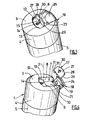
Figure 5 is a perspective view of the second embodiment of the cap according to the invention, and shows the stopping device separated from the cap; -
Figure 6 is an axial-section view of the cap fromFigure 5 mounted on the container and shows the stopping device in closed position; and -
Figures 7 and 8 are axial-section views of the cap fromFigure 5 and show, respectively, the stopping device in the intermediate open position and in open position. - Figures to 4 show a
closure cap 1 with anaxis 2. Thecap 1 includes an end plate orwall 3 largely flat and disk-shaped. A generallycylindrical skirt 4 depends from the periphery of thewall 3. - The
cap 1 is mounted on acontainer 5, here a flexible tube containing for example a pasty, cream-type product. The attachment of thecap 1 on thecontainer 5 is obtained by known means (screwing, latching, etc.). Thecontainer 5 includes a collar 6 whose axis is largely coincident with theaxis 2 of thecap 1 in the assembled state (seeFigure 6 ). - The
cap 1 includes acavity 7 for which room is made from theend wall 3 towards thecontainer 5. In the implementation shown, thecavity 7 is limited by twolateral faces 8 perpendicular to theend wall 3 and mutually parallel, a face referred to as "front" 9 perpendicular to thelateral faces 8, and abottom 10. As a variant, thefront face 9 could be curved, for example bulging towards thecavity 7. Thecavity 7 does not have a "rear" face, but opens into thelateral skirt 4 by locally interrupting it. In the area of this local interruption of thelateral skirt 4, thecavity 7 can include azone 11 recessed towards thecontainer 5 as compared to thebottom 10, thereby forming a step. Thecavity 7 thus extends from thelateral skirt 4 over about half the diameter of thecap 1, and is further largely centred laterally relative to thetransverse wall 3. The width of thecavity 7, meaning the distance between the lateral faces 8, is on the order of 2 to 3 cm (roughly the width of a thumb). - Furthermore, the lateral faces 8 extend beyond the
front face 9 up to anend face 12 generally perpendicular to said lateral faces 8. Here theend face 12 is slightly curved. Awall 13 largely parallel to theend wall 3 connects theend face 12 to thefront face 9. Thewall 13 is recessed towards thecontainer 5 as compared to theend wall 3. In the embodiment fromFigures 1 to 4 , thewall 13 is located axially between theend wall 3 and the bottom 10 of thecavity 7. - In the
wall 13, room is made for anorifice 14 withaxis 15, which allows the flow of the contents out of thecontainer 5. Theorifice 14 has dimensions smaller than that of the collar 6, and itsaxis 15 is largely parallel to theaxis 2 of thecap 1, while also being offset from it. - Means of sealing between the
cap 1 and thecontainer 5 are provided. As shown inFigure 6 , these means can consist of aninner skirt 16 extending below theorifice 14 towards thecontainer 5 and intended to cooperate with the inner face of the collar 6. - Furthermore, the
cap 1 includes anintegrated stopper member 17, linked to thelateral skirt 4, which in closed position allows stopping of theorifice 14 and which can be moved towards an open position in which theorifice 14 is cleared. The body of the cap 1 (endwall 3 and lateral skirt 4) and the stoppingdevice 17 are made of a single part by moulding plastic. The stoppingdevice 17 is described in its closed position (Figure 1 ). - The
member 17 includes anactuating part 18 in the shape of an L-shaped tab. - The actuating
part 18 includes afirst part 19 placed in the local interruption of thelateral skirt 4 for which room is made by thecavity 7, and forms with the lateral skirt 4 a largely continuous and cylindrical surface. Afirst end 20 of thefirst portion 19, which is largely orthogonal to theaxis 2, is joined to thelateral skirt 4 by twobands 21 which are oriented largely parallel to theaxis 2 and separated from each other along saidfirst end 20. Thebands 21 have a relatively small thickness which makes them flexible. The zone included between the twobands 21 may or may not be connected to thelateral skirt 4. As a variant, the twobands 21 could be replaced by another type of connection, for example a thin film. Thesecond end 22 of thefirst portion 19 is located largely in the plane of theend wall 3 of thecap 1. - The actuating
part 18 further includes asecond portion 23 extending from thesecond end 22 of thefirst portion 19, opposite thecavity 7 and largely parallel to theend wall 3 and extending it. Thelateral walls 24 of the second portion 23 (oriented largely perpendicular to the first portion 19) are each located near alateral face 8 of thecavity 7. Thesecond portion 23 extends up to a line forming thesecond end 25 of theactuating part 19 which is largely parallel to thesecond end 22 of thefirst portion 19. Thesecond end 25 is located away from thefront face 9 on thecavity 7 side. Finally, animprint 26 is arranged in thesecond portion 23 to receive the user's finger. - The
member 17 further includes a stoppingpart 27 formed from a flap extending from thesecond end 25 of theactuating part 18, largely parallel to theend wall 3. The thickness of the flap is here roughly equal to the distance between the end of thefront face 9 opposite the bottom 10 of thecavity 7 and theend wall 3. The stoppingpart 27 extends up to itsfree end 28, located near theend face 12 and having a shape complementary to it. The lateral edges 29 of the stoppingpart 27 extend as an extension of the lateral edges 24 of thesecond portion 23 of theactuating part 18. The stoppingpart 27 furthermore includes atip 30 projecting towards the inside of thecap 1, and intended to mate with and seal theorifice 14, in the closed position.
The stoppingpart 27 is linked to theactuating part 18 by ahinge 31 formed of a very narrow thin-film extending parallel to thesecond end 25 of theactuating part 18. - Consequently, in the closed position, the stopping
device 17 fills the hollows formed in theend wall 3 and thelateral skirt 4 with thecap 1 thus having a visible shape which is largely cylindrical limited by a transverse wall that is flat overall. As a variant, the stoppingdevice 17 might not be placed exactly continuously with the body of thecap 1, but be slightly depressed or slightly projecting. - The material used and the thickness chosen make the
actuating part 18 and the stoppingpart 27 rigid and largely undeformable (in the case of normal use by a person). - The second embodiment of the
cap 1 according to the invention is shown inFigure 5 . Thecap 1 fromFigure 5 generally has the same features as those previously described, with the following differences. - The
cap 1 has a parallelepiped shape, theend wall 3 is predominantly square, and thelateral skirt 4 has four planar faces. - The
first portion 19 of theactuating part 18 has afirst end 20 which is largely straight and connected to thelateral skirt 4 by articulation means made up of a rigidcentral band 32, a firstflexible zone 33 placed to one side of therigid band 32 and connected to thelateral skirt 4, and a secondflexible zone 34 placed on the opposite side of therigid band 32 and linked to thefirst end 20. These different elements (rigid band 32 andflexible zones 33 and 34) are largely linear and oriented parallel to thefirst end 20. They are made up of the same material, with thecentral band 32 being thicker, which gives it its rigidity. - The
wall 13 is located largely in the same axial area as the bottom 10 of thecavity 7. Thus asmall bar 35 is defined which projects from the bottom 9 towards theend wall 3, between theorifice 14 and thecavity 7, where a space exists between the free end of thesmall bar 35 and theend wall 3. - Further, the
orifice 14 is surrounded by aduct 36 extending in the direction of theend wall 3 and instead of thetip 30 the stoppingpart 27 has aseal skirt 37 intended to mate with the outside of theduct 36 in closed position. - Additionally, at least one rib 38 (here there are two) projects from the stopping
part 27 towards the inside of thecap 1, in closed position. In the closed position of the stoppingdevice 17, theribs 38 rest on thesmall bar 35, the thickness e of the flap being suited for said flap to be located largely in the same plane as theend wall 3. In the open position of the stoppingdevice 17, theribs 38 mate with thefront face 9 of thecavity 7. They thus make it possible to place the means of articulation of the stoppingdevice 17 under tension on the body of thecap 1 and, consequently, to assure the locking of the stoppingpart 27 in open position, Relative to the implementation ofFigures 1 to 4 , the ribs make it possible to obtain this locking with a reduced thickness e resulting in a savings of material. - Furthermore, the actuating
part 18 could include means laid out on the inside face of the actuating part 18 (tabs, curved shape, etc.) which, since they are intended to mate with a guiding ramp laid out in thecavity 7 by sliding, would make it possible to ease the passage of thestopper member 17 from the closed to open position (as will be seen farther on), by limiting the rubbing surface. The guiding ramp could notably be made up by the shoulder between thecavity 7 and thezone 11. - Finally, for aesthetic reasons, the
free end 28 of the stoppingpart 27 is not curved but largely linear. - Now the operation of the stopping device according to the invention is described by referring to
Figures 6 to 8 . These figures show the cap fromFigure 5 , but of course, the operation is similar in the case of the cap fromFigures 1 to 4 . - In the closed position of the stopping device 17 (
Figure 6 ), the stoppingpart 27 rests on the small bar 35 (or thewall 13 in the case of the first embodiment), theorifice 14 being stopped through the seal skirt 37 (or the tip 38). Thesecond portion 23 of theactuating part 18 is located largely in the same plane as the stoppingpart 27 and is kept in this position notably because of the mating between the seal skirt 37 (or tip 30) and theorifice 14, and by the tension exerted on the articulation means.
When a user wishes to pour out the contents from thecontainer 5, they press on theactuation part 18 in the area of theimprint 26 with a finger. Consequently, the actuatingpart 18 is pushed in towards the front in thecavity 7, thesecond end 25 approaches the bottom 10 in the front face 9 (Figure 7 ). During this pushing in, the actuating part is driven in the pivoting motion relative to therigid band 32, around the secondflexible zone 34 of the articulation means, whereas therigid band 32 is itself driven In a pivoting motion relative to the firstflexible zone 33. Because of this double pivoting, the actuatingpart 18 is moved perpendicularly to thefront wall 9 and by separating from it. This "recoil" movement of theactuating part 18 is necessary to allow the opening of thestopper member 17, because theactuating part 18 is not deformable. In the case of the first embodiment, there is no double pivoting, but the flexibility of thepins 21 makes it possible to obtain the same depressing movement and recoil of theactuating part 18. - Depressing the
actuating part 18 in thecavity 7 drives the pivoting of the stoppingpart 27 around thehinge 31 by the pushing exerted on the small bar 35 (or the edge between thefront wall 9 and the wall 13). Thefront face 9 thus forms a stop. This pivoting is made possible because thehinge 31 is located at a sufficient distance d1 from thefront face 9 of the side of thecavity 7. As theactuating part 18 moves down into thecavity 7, thesecond end 25 approaches thefront face 9, the stoppingpart 27 slides along thefront face 9 tilting more and more relative to theend wall 3 of thecap 1, and the articulation means (band 32 andflexible zones 33 and 34) approach a plane orthogonal to theaxis 2 of thecap 1. - In the open position of the stopper member 17 (
Figure 8 ), the actuatingpart 18 is mainly lodged in thecavity 7, since asecond portion 23 is stopped against the bottom 10, which stopped the lowering movement. The actuatingpart 18 recoiled a distance d2, less than or equal to the height of the articulation means (meaning their axial dimension considered when thestopper member 17 is in closed position). The stoppingpart 27 is largely parallel to thefront face 9 and to its contact, since theorifice 14 is thus cleared and allows the distribution of the product contained in thecontainer 5. - Advantageously, the thickness e of the stopping part 27 (
Figures 1 to 4 ) or the thickness e increased by the thickness of the ribs 38 (Figure 5 ), the distance d1 between thehinge 31 and thefront face 9, the recoil distance d2 of theactuating part 18 and the height of the articulation means are intended so that, in open position, the stoppingpart 27 is maintained stopped against thefront face 9 by the tension of the articulation means. For this purpose, it can be provided in particular that d1 is less than d2. - To re-close the
member 17, it is sufficient for the user to exert a push on the stoppingpart 27 towards theorifice 14. With an inverse movement from that described previously, the different parts of themember 17 then return to the position ofFigure 6 . - Thus, the invention brings a decisive improvement to the prior art, by providing a stopping device that can be very easily opened by a simple push exerted with the finger, leading to a significant clearing of the outlet orifice and to staying in open position without action by the user.
- It is self-evident that the invention is not limited to the embodiments described above as examples, but rather encompasses all implementation variants. Notably, the stopping device could have larger dimensions; the end wall of the cap would then have very reduced dimensions or even be nonexistent.
Claims (10)
- A container closure (1) comprising:- a body which is mountable on a container and includes a skirt (4) closed at one end by an end wall (3) provided with an orifice (14);- the end wall (3) having a cavity (7) and a stop (9) between the cavity (7) and the orifice (14);- a stopper member (17) including a stopping part (27) positioned to block the orifice (14) and an actuating part positioned over the cavity (7);- the actuating part having a first end (20) articulated to the body and a second end (25) connected to the stopping part (27) by a hinge (31);- characterised in that the stopper member is movable between a closed position in which the stopping part (27) blocks the orifice (14) and the actuating part (18) is spaced from the bottom of the cavity, and an open position in which the actuating part is pressed into the cavity and the stopping part is lifted away from the orifice by causing it to be pressed against the stop and to pivot about the hinge (31).
- A closure (1) according to Claim 1, wherein the hinge (31) is positioned at a distance (d1) from the stop (9) on the cavity side.
- A closure (1) according to Claim 1 or Claim 2, wherein the movement of the stopper member (17) to the open position includes a component of movement which is substantially transverse the main axis (2) of the closure.
- A closure (1) according to any of Claims 1 to 3, wherein the cavity (7) is of generally parallelepiped shape, having a bottom (10) and two parallel side walls (8).
- A closure according to any preceding claim, wherein the cavity (7) opens in part into the skirt (4) and wherein the means of articulation (21, 32, 33, 34) of the actuating part (18) to the body are located away from the end wall (3).
- A closure according to any preceding claim, wherein in the open position the stopping part (27) is wedged against the stop (9).
- A closure according to any preceding claim, wherein the means of articulation of the actuating part (18) on the body of the cap (1) includes at least one band of rigid material (32) whose first end is bound by a first flexible zone (33) to the body of the cap (1) and whose second end is bound by a second flexible zone (34) to the actuating part (18), with said flexible zones (33 and 34) being largely parallel to each other and orthogonal to the lateral walls (8) of the cavity (7).
- A closure according to any preceding claim, wherein the stopping part (27) includes a flap whose thickness (e) is less than or roughly equal to the height of the articulation means, between the body of the cap (1) and the actuating part (18).
- A closure according to any preceding claim, wherein the stopping part (27) includes at least one rib (38) projecting towards the inside of the cap (1), in closed position of the stopping device (17), said rib (38) being intended to cooperate with the stop (9) to allow locking of the stopping part (27) in open position.
- An assembly including a container (5) provided with an opening and also a closure (1) according to any preceding claim.
Priority Applications (1)
| Application Number | Priority Date | Filing Date | Title |
|---|---|---|---|
| PL06254476T PL1770021T3 (en) | 2005-08-29 | 2006-08-29 | Plastic closure |
Applications Claiming Priority (1)
| Application Number | Priority Date | Filing Date | Title |
|---|---|---|---|
| FR0508818A FR2890050A1 (en) | 2005-08-29 | 2005-08-29 | Closure for e.g. flexible tube with cream, has stopping part closing orifice and actuating part spaced from base in stopping device`s closed position, where stopping part is pivoted around hinge to release orifice in device`s open position |
Publications (2)
| Publication Number | Publication Date |
|---|---|
| EP1770021A1 EP1770021A1 (en) | 2007-04-04 |
| EP1770021B1 true EP1770021B1 (en) | 2008-04-30 |
Family
ID=36218417
Family Applications (1)
| Application Number | Title | Priority Date | Filing Date |
|---|---|---|---|
| EP06254476A Not-in-force EP1770021B1 (en) | 2005-08-29 | 2006-08-29 | Plastic closure |
Country Status (6)
| Country | Link |
|---|---|
| EP (1) | EP1770021B1 (en) |
| AT (1) | ATE393738T1 (en) |
| DE (1) | DE602006001044T2 (en) |
| ES (1) | ES2306391T3 (en) |
| FR (1) | FR2890050A1 (en) |
| PL (1) | PL1770021T3 (en) |
Family Cites Families (2)
| Publication number | Priority date | Publication date | Assignee | Title |
|---|---|---|---|---|
| DE7818747U1 (en) * | 1978-06-22 | 1978-09-28 | Karl Ostmann Fa | Can with a litter closure |
| US6290094B1 (en) * | 1996-03-08 | 2001-09-18 | Graham Packaging Company, L.P. | Integrally blow-molded container and closure |
-
2005
- 2005-08-29 FR FR0508818A patent/FR2890050A1/en active Pending
-
2006
- 2006-08-29 EP EP06254476A patent/EP1770021B1/en not_active Not-in-force
- 2006-08-29 ES ES06254476T patent/ES2306391T3/en active Active
- 2006-08-29 DE DE602006001044T patent/DE602006001044T2/en active Active
- 2006-08-29 PL PL06254476T patent/PL1770021T3/en unknown
- 2006-08-29 AT AT06254476T patent/ATE393738T1/en not_active IP Right Cessation
Also Published As
| Publication number | Publication date |
|---|---|
| EP1770021A1 (en) | 2007-04-04 |
| FR2890050A1 (en) | 2007-03-02 |
| PL1770021T3 (en) | 2008-10-31 |
| DE602006001044T2 (en) | 2009-07-02 |
| ATE393738T1 (en) | 2008-05-15 |
| ES2306391T3 (en) | 2008-11-01 |
| DE602006001044D1 (en) | 2008-06-12 |
Similar Documents
| Publication | Publication Date | Title |
|---|---|---|
| KR101477879B1 (en) | Child resistant bulk dose dispensing unit | |
| US5573127A (en) | Cap for liquid containers | |
| US4301948A (en) | Dispenser for paste-like products with a manually actuatable piston | |
| US4022352A (en) | Container cover and safety closure | |
| CA2434158C (en) | Toggle-action dispensing closure with an actuation-prevention abutment and a recessed striker rib | |
| KR100250016B1 (en) | Dispensing seal | |
| US5131555A (en) | Beverage container opening top | |
| US9987647B2 (en) | Dispensing head for a cosmetic product, associated device and method | |
| ZA200604947B (en) | Aerosol valve actuator | |
| WO2002059006A1 (en) | Two piece hinged closure | |
| US20020175137A1 (en) | Dispensing cap with cover | |
| US5022566A (en) | Press-open side dispensing closure | |
| US5647498A (en) | Hinged container cap | |
| EP0819615A1 (en) | Container cap including a primary cap and a secondary cap joined by a hinge | |
| EP1770021B1 (en) | Plastic closure | |
| US11542073B2 (en) | Childproof container closure | |
| AU2006281256B2 (en) | Liquid dispensers | |
| US6478194B2 (en) | Dispensing closure for a container | |
| USRE31408E (en) | Dispenser for paste-like products with a manually actuatable piston | |
| EP2870077B1 (en) | A dispensing closure | |
| EP0850853B1 (en) | Valves | |
| US20150096992A1 (en) | Sliding cap and tube | |
| CN112041237A (en) | Liquid dispenser with squeezable liquid reservoir | |
| JP6002219B2 (en) | Plug member and dispenser having the plug member | |
| US10604309B2 (en) | Travel bottle with slide lock |
Legal Events
| Date | Code | Title | Description |
|---|---|---|---|
| PUAI | Public reference made under article 153(3) epc to a published international application that has entered the european phase |
Free format text: ORIGINAL CODE: 0009012 |
|
| AK | Designated contracting states |
Kind code of ref document: A1 Designated state(s): AT BE BG CH CY CZ DE DK EE ES FI FR GB GR HU IE IS IT LI LT LU LV MC NL PL PT RO SE SI SK TR |
|
| AX | Request for extension of the european patent |
Extension state: AL BA HR MK YU |
|
| 17P | Request for examination filed |
Effective date: 20070917 |
|
| 17Q | First examination report despatched |
Effective date: 20071022 |
|
| AKX | Designation fees paid |
Designated state(s): AT BE BG CH CY CZ DE DK EE ES FI FR GB GR HU IE IS IT LI LT LU LV MC NL PL PT RO SE SI SK TR |
|
| GRAP | Despatch of communication of intention to grant a patent |
Free format text: ORIGINAL CODE: EPIDOSNIGR1 |
|
| RIN1 | Information on inventor provided before grant (corrected) |
Inventor name: ORSAUD, ANDRE Inventor name: BENOIT-GONIN, CLAUDE Inventor name: BARDET, PHILIPP |
|
| GRAS | Grant fee paid |
Free format text: ORIGINAL CODE: EPIDOSNIGR3 |
|
| GRAA | (expected) grant |
Free format text: ORIGINAL CODE: 0009210 |
|
| AK | Designated contracting states |
Kind code of ref document: B1 Designated state(s): AT BE BG CH CY CZ DE DK EE ES FI FR GB GR HU IE IS IT LI LT LU LV MC NL PL PT RO SE SI SK TR |
|
| REG | Reference to a national code |
Ref country code: GB Ref legal event code: FG4D |
|
| REG | Reference to a national code |
Ref country code: CH Ref legal event code: EP |
|
| REG | Reference to a national code |
Ref country code: IE Ref legal event code: FG4D Free format text: LANGUAGE OF EP DOCUMENT: FRENCH |
|
| REF | Corresponds to: |
Ref document number: 602006001044 Country of ref document: DE Date of ref document: 20080612 Kind code of ref document: P |
|
| PG25 | Lapsed in a contracting state [announced via postgrant information from national office to epo] |
Ref country code: SI Free format text: LAPSE BECAUSE OF FAILURE TO SUBMIT A TRANSLATION OF THE DESCRIPTION OR TO PAY THE FEE WITHIN THE PRESCRIBED TIME-LIMIT Effective date: 20080430 |
|
| NLV1 | Nl: lapsed or annulled due to failure to fulfill the requirements of art. 29p and 29m of the patents act | ||
| PG25 | Lapsed in a contracting state [announced via postgrant information from national office to epo] |
Ref country code: PT Free format text: LAPSE BECAUSE OF FAILURE TO SUBMIT A TRANSLATION OF THE DESCRIPTION OR TO PAY THE FEE WITHIN THE PRESCRIBED TIME-LIMIT Effective date: 20080930 Ref country code: NL Free format text: LAPSE BECAUSE OF FAILURE TO SUBMIT A TRANSLATION OF THE DESCRIPTION OR TO PAY THE FEE WITHIN THE PRESCRIBED TIME-LIMIT Effective date: 20080430 Ref country code: FI Free format text: LAPSE BECAUSE OF FAILURE TO SUBMIT A TRANSLATION OF THE DESCRIPTION OR TO PAY THE FEE WITHIN THE PRESCRIBED TIME-LIMIT Effective date: 20080430 Ref country code: BG Free format text: LAPSE BECAUSE OF FAILURE TO SUBMIT A TRANSLATION OF THE DESCRIPTION OR TO PAY THE FEE WITHIN THE PRESCRIBED TIME-LIMIT Effective date: 20080730 |
|
| PGFP | Annual fee paid to national office [announced via postgrant information from national office to epo] |
Ref country code: ES Payment date: 20080922 Year of fee payment: 3 |
|
| REG | Reference to a national code |
Ref country code: PL Ref legal event code: T3 |
|
| REG | Reference to a national code |
Ref country code: ES Ref legal event code: FG2A Ref document number: 2306391 Country of ref document: ES Kind code of ref document: T3 |
|
| PG25 | Lapsed in a contracting state [announced via postgrant information from national office to epo] |
Ref country code: AT Free format text: LAPSE BECAUSE OF FAILURE TO SUBMIT A TRANSLATION OF THE DESCRIPTION OR TO PAY THE FEE WITHIN THE PRESCRIBED TIME-LIMIT Effective date: 20080430 Ref country code: LV Free format text: LAPSE BECAUSE OF FAILURE TO SUBMIT A TRANSLATION OF THE DESCRIPTION OR TO PAY THE FEE WITHIN THE PRESCRIBED TIME-LIMIT Effective date: 20080430 |
|
| PG25 | Lapsed in a contracting state [announced via postgrant information from national office to epo] |
Ref country code: IS Free format text: LAPSE BECAUSE OF FAILURE TO SUBMIT A TRANSLATION OF THE DESCRIPTION OR TO PAY THE FEE WITHIN THE PRESCRIBED TIME-LIMIT Effective date: 20080830 |
|
| PG25 | Lapsed in a contracting state [announced via postgrant information from national office to epo] |
Ref country code: CZ Free format text: LAPSE BECAUSE OF FAILURE TO SUBMIT A TRANSLATION OF THE DESCRIPTION OR TO PAY THE FEE WITHIN THE PRESCRIBED TIME-LIMIT Effective date: 20080430 Ref country code: LT Free format text: LAPSE BECAUSE OF FAILURE TO SUBMIT A TRANSLATION OF THE DESCRIPTION OR TO PAY THE FEE WITHIN THE PRESCRIBED TIME-LIMIT Effective date: 20080430 Ref country code: SE Free format text: LAPSE BECAUSE OF FAILURE TO SUBMIT A TRANSLATION OF THE DESCRIPTION OR TO PAY THE FEE WITHIN THE PRESCRIBED TIME-LIMIT Effective date: 20080731 Ref country code: DK Free format text: LAPSE BECAUSE OF FAILURE TO SUBMIT A TRANSLATION OF THE DESCRIPTION OR TO PAY THE FEE WITHIN THE PRESCRIBED TIME-LIMIT Effective date: 20080430 |
|
| ET | Fr: translation filed | ||
| PG25 | Lapsed in a contracting state [announced via postgrant information from national office to epo] |
Ref country code: RO Free format text: LAPSE BECAUSE OF FAILURE TO SUBMIT A TRANSLATION OF THE DESCRIPTION OR TO PAY THE FEE WITHIN THE PRESCRIBED TIME-LIMIT Effective date: 20080430 Ref country code: SK Free format text: LAPSE BECAUSE OF FAILURE TO SUBMIT A TRANSLATION OF THE DESCRIPTION OR TO PAY THE FEE WITHIN THE PRESCRIBED TIME-LIMIT Effective date: 20080430 |
|
| PGFP | Annual fee paid to national office [announced via postgrant information from national office to epo] |
Ref country code: BE Payment date: 20080829 Year of fee payment: 3 Ref country code: PL Payment date: 20080814 Year of fee payment: 3 |
|
| PLBE | No opposition filed within time limit |
Free format text: ORIGINAL CODE: 0009261 |
|
| STAA | Information on the status of an ep patent application or granted ep patent |
Free format text: STATUS: NO OPPOSITION FILED WITHIN TIME LIMIT |
|
| PG25 | Lapsed in a contracting state [announced via postgrant information from national office to epo] |
Ref country code: MC Free format text: LAPSE BECAUSE OF NON-PAYMENT OF DUE FEES Effective date: 20080831 |
|
| 26N | No opposition filed |
Effective date: 20090202 |
|
| PG25 | Lapsed in a contracting state [announced via postgrant information from national office to epo] |
Ref country code: EE Free format text: LAPSE BECAUSE OF FAILURE TO SUBMIT A TRANSLATION OF THE DESCRIPTION OR TO PAY THE FEE WITHIN THE PRESCRIBED TIME-LIMIT Effective date: 20080430 |
|
| PG25 | Lapsed in a contracting state [announced via postgrant information from national office to epo] |
Ref country code: IE Free format text: LAPSE BECAUSE OF NON-PAYMENT OF DUE FEES Effective date: 20080829 |
|
| BERE | Be: lapsed |
Owner name: OBRIST CLOSURES SWITZERLAND GMBH Effective date: 20090831 |
|
| PGFP | Annual fee paid to national office [announced via postgrant information from national office to epo] |
Ref country code: IT Payment date: 20090831 Year of fee payment: 4 |
|
| PG25 | Lapsed in a contracting state [announced via postgrant information from national office to epo] |
Ref country code: BE Free format text: LAPSE BECAUSE OF NON-PAYMENT OF DUE FEES Effective date: 20090831 |
|
| PG25 | Lapsed in a contracting state [announced via postgrant information from national office to epo] |
Ref country code: LU Free format text: LAPSE BECAUSE OF NON-PAYMENT OF DUE FEES Effective date: 20080829 Ref country code: CY Free format text: LAPSE BECAUSE OF FAILURE TO SUBMIT A TRANSLATION OF THE DESCRIPTION OR TO PAY THE FEE WITHIN THE PRESCRIBED TIME-LIMIT Effective date: 20080430 Ref country code: HU Free format text: LAPSE BECAUSE OF FAILURE TO SUBMIT A TRANSLATION OF THE DESCRIPTION OR TO PAY THE FEE WITHIN THE PRESCRIBED TIME-LIMIT Effective date: 20081101 |
|
| PG25 | Lapsed in a contracting state [announced via postgrant information from national office to epo] |
Ref country code: TR Free format text: LAPSE BECAUSE OF FAILURE TO SUBMIT A TRANSLATION OF THE DESCRIPTION OR TO PAY THE FEE WITHIN THE PRESCRIBED TIME-LIMIT Effective date: 20080430 |
|
| REG | Reference to a national code |
Ref country code: ES Ref legal event code: FD2A Effective date: 20090831 |
|
| PG25 | Lapsed in a contracting state [announced via postgrant information from national office to epo] |
Ref country code: GR Free format text: LAPSE BECAUSE OF FAILURE TO SUBMIT A TRANSLATION OF THE DESCRIPTION OR TO PAY THE FEE WITHIN THE PRESCRIBED TIME-LIMIT Effective date: 20080731 |
|
| REG | Reference to a national code |
Ref country code: CH Ref legal event code: PL |
|
| PG25 | Lapsed in a contracting state [announced via postgrant information from national office to epo] |
Ref country code: CH Free format text: LAPSE BECAUSE OF NON-PAYMENT OF DUE FEES Effective date: 20100831 Ref country code: LI Free format text: LAPSE BECAUSE OF NON-PAYMENT OF DUE FEES Effective date: 20100831 |
|
| PG25 | Lapsed in a contracting state [announced via postgrant information from national office to epo] |
Ref country code: IT Free format text: LAPSE BECAUSE OF NON-PAYMENT OF DUE FEES Effective date: 20100829 Ref country code: PL Free format text: LAPSE BECAUSE OF NON-PAYMENT OF DUE FEES Effective date: 20090829 |
|
| REG | Reference to a national code |
Ref country code: PL Ref legal event code: LAPE |
|
| PG25 | Lapsed in a contracting state [announced via postgrant information from national office to epo] |
Ref country code: ES Free format text: LAPSE BECAUSE OF NON-PAYMENT OF DUE FEES Effective date: 20090830 |
|
| PGFP | Annual fee paid to national office [announced via postgrant information from national office to epo] |
Ref country code: GB Payment date: 20120821 Year of fee payment: 7 |
|
| PGFP | Annual fee paid to national office [announced via postgrant information from national office to epo] |
Ref country code: FR Payment date: 20120906 Year of fee payment: 7 Ref country code: DE Payment date: 20120822 Year of fee payment: 7 |
|
| GBPC | Gb: european patent ceased through non-payment of renewal fee |
Effective date: 20130829 |
|
| PG25 | Lapsed in a contracting state [announced via postgrant information from national office to epo] |
Ref country code: DE Free format text: LAPSE BECAUSE OF NON-PAYMENT OF DUE FEES Effective date: 20140301 |
|
| REG | Reference to a national code |
Ref country code: FR Ref legal event code: ST Effective date: 20140430 |
|
| REG | Reference to a national code |
Ref country code: DE Ref legal event code: R119 Ref document number: 602006001044 Country of ref document: DE Effective date: 20140301 |
|
| PG25 | Lapsed in a contracting state [announced via postgrant information from national office to epo] |
Ref country code: GB Free format text: LAPSE BECAUSE OF NON-PAYMENT OF DUE FEES Effective date: 20130829 |
|
| PG25 | Lapsed in a contracting state [announced via postgrant information from national office to epo] |
Ref country code: FR Free format text: LAPSE BECAUSE OF NON-PAYMENT OF DUE FEES Effective date: 20130902 |