EP1769976A1 - Pedestrian impact sensing apparatus for a vehicle bumper - Google Patents
Pedestrian impact sensing apparatus for a vehicle bumper Download PDFInfo
- Publication number
- EP1769976A1 EP1769976A1 EP06076687A EP06076687A EP1769976A1 EP 1769976 A1 EP1769976 A1 EP 1769976A1 EP 06076687 A EP06076687 A EP 06076687A EP 06076687 A EP06076687 A EP 06076687A EP 1769976 A1 EP1769976 A1 EP 1769976A1
- Authority
- EP
- European Patent Office
- Prior art keywords
- airflow
- air channel
- impact
- sensor
- responsive
- Prior art date
- Legal status (The legal status is an assumption and is not a legal conclusion. Google has not performed a legal analysis and makes no representation as to the accuracy of the status listed.)
- Withdrawn
Links
- 210000003195 fascia Anatomy 0.000 claims abstract description 10
- 230000035945 sensitivity Effects 0.000 claims description 9
- 239000011800 void material Substances 0.000 claims description 2
- 238000000034 method Methods 0.000 claims 4
- 239000013518 molded foam Substances 0.000 claims 1
- 239000006260 foam Substances 0.000 abstract description 10
- 238000001514 detection method Methods 0.000 abstract description 7
- 238000000465 moulding Methods 0.000 abstract description 2
- 230000001052 transient effect Effects 0.000 description 8
- 238000010586 diagram Methods 0.000 description 5
- 230000003068 static effect Effects 0.000 description 2
- XUIMIQQOPSSXEZ-UHFFFAOYSA-N Silicon Chemical compound [Si] XUIMIQQOPSSXEZ-UHFFFAOYSA-N 0.000 description 1
- 208000027418 Wounds and injury Diseases 0.000 description 1
- 239000002250 absorbent Substances 0.000 description 1
- 230000006378 damage Effects 0.000 description 1
- 230000003247 decreasing effect Effects 0.000 description 1
- 238000006073 displacement reaction Methods 0.000 description 1
- 208000014674 injury Diseases 0.000 description 1
- 239000000463 material Substances 0.000 description 1
- 238000012986 modification Methods 0.000 description 1
- 230000004048 modification Effects 0.000 description 1
- 230000003287 optical effect Effects 0.000 description 1
- 238000004904 shortening Methods 0.000 description 1
- 229910052710 silicon Inorganic materials 0.000 description 1
- 239000010703 silicon Substances 0.000 description 1
- 230000000153 supplemental effect Effects 0.000 description 1
Images


Classifications
-
- B—PERFORMING OPERATIONS; TRANSPORTING
- B60—VEHICLES IN GENERAL
- B60R—VEHICLES, VEHICLE FITTINGS, OR VEHICLE PARTS, NOT OTHERWISE PROVIDED FOR
- B60R21/00—Arrangements or fittings on vehicles for protecting or preventing injuries to occupants or pedestrians in case of accidents or other traffic risks
- B60R21/01—Electrical circuits for triggering passive safety arrangements, e.g. airbags, safety belt tighteners, in case of vehicle accidents or impending vehicle accidents
- B60R21/013—Electrical circuits for triggering passive safety arrangements, e.g. airbags, safety belt tighteners, in case of vehicle accidents or impending vehicle accidents including means for detecting collisions, impending collisions or roll-over
- B60R21/0136—Electrical circuits for triggering passive safety arrangements, e.g. airbags, safety belt tighteners, in case of vehicle accidents or impending vehicle accidents including means for detecting collisions, impending collisions or roll-over responsive to actual contact with an obstacle, e.g. to vehicle deformation, bumper displacement or bumper velocity relative to the vehicle
Definitions
- the present invention relates to pedestrian impact detection for a vehicle, and more particularly to an airflow sensing apparatus incorporated into a vehicle bumper.
- a vehicle can be equipped with deployable safety devices designed to reduce injury to a pedestrian struck by the vehicle.
- the vehicle may be equipped with one or more pedestrian air bags and/or a device for changing the inclination angle of the hood.
- many deployment systems include one or more pressure or deformation responsive strips disposed in or on the front and/or rear bumpers. See, for example, the U.S. Patent No. 6,784,792 to Mattes et al. , which suggests the use of wire strain, piezoelectric film, magneto-electric, magneto-resistive or optical sensor elements on the bumper fascia.
- U.S. Patent No. 6,607,212 to Reimer et al. light energy scattered within a block of translucent polymeric foam disposed between the bumper fascia and a rigid bumper frame element is detected to form a measure of crush experienced in a collision.
- the present invention is directed to an improved impact sensing apparatus including a laterally extending air channel within a block of foam or other crushable medium disposed between the bumper fascia and a rigid bumper frame element, and one or more airflow sensors for detecting air displacement within the air channel.
- the air channel may be defined by a flexible hollow tube embedded within the crushable medium or by a molded-in air cavity in cases where the crushable medium is formed by molding.
- the measured airflow provides a measure of crush rate, and two or more airflow sensors may be distributed within the air channel to optimize impact detection response time and to identify the impact location. Additionally, the size and placement of the air channel within the compressible medium can be configured to control the sensitivity of the sensing apparatus.
- the reference numeral 10 designates a vehicle that is equipped with one or more pedestrian safety devices (PSDs) and a sensing system for deploying the safety devices when a pedestrian impact is detected.
- PSDs are designated by a single block 12, and may include one or more pedestrian air bags and a mechanism for changing the inclination angle of the vehicle hood.
- the PSDs are selectively activated by a microprocessor-based electronic control unit (ECU) 14, which issues a deployment command on line 16 when a pedestrian impact is detected.
- the ECU 14 detects pedestrian impacts based on airflow signals produced by one or more airflow sensors 18, 20.
- the airflow sensors 18, 20 are disposed in an air channel 22 that extends laterally across the vehicle; that is, perpendicular to the direction of vehicle travel.
- the air channel 22 resides within a block 24 of foam or other crushable energy-absorbent material disposed between a bumper fascia 26 at the leading edge of vehicle 10 and a rigid bumper frame element 28 that extends substantially parallel to the bumper fascia 26.
- the air channel 22 may be defined by an open-ended flexible tube 30 passing through the foam block 24 as depicted in FIG. 2, or simply by an air-filled void or cavity in the foam block 24 as depicted in FIG. 1. In either case, the airflow sensors 18, 20 measure airflow without substantially impeding airflow within the air channel 22.
- FIG. 2 depicts the fascia 26 and foam block 24 when the vehicle 10 impacts a soft-bodied object 32 such as a pedestrian leg form.
- the impact locally crushes the foam block 24 and proportionally crushes the air passage 22 as indicated by the reference numeral 22'.
- the localized crushing of air passage 22 produces transient airflows away from the crush zone as indicated by the arrows 34a and 34b.
- the airflows are respectively detected by the sensors 18 and 20, and the airflow signals produced by sensors 18 and 20 provide a measure of the crush rate and impact location to ECU 14.
- FIG. 2 depicts an additional pair of airflow sensors 36, 38 disposed approximately at the midpoint of the air passage 22.
- the addition of sensors 36 and 38 improves the response time of the sensing apparatus by shortening the distance between an impact and a pair of airflow sensors.
- the difference between the airflow signals produced by sensors 36 and 38 provides an early indication of the airflow direction within air passage 22; since the sensors 36 and 38 are located in the mid-section of the air passage 22, the airflow direction tells ECU 14 which side of the vehicle 10 was impacted by the object 32.
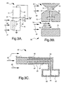
- FIGS. 3A-3C depict three examples of suitable airflow sensors.
- FIG. 3A depicts a heated element sensor 40;
- FIG. 3B depicts a venturi sensor 50; and
- FIG. 3C depicts a Pitot tube sensor 60.
- the heated element sensor 40 comprises four resistors 41, 42, 43, 44 configured in a conventional Wheatstone bridge arrangement and a differential amplifier 45 responsive to the potential difference between the bridge nodes 46 and 47.
- the amplifier 45 adjusts the bridge voltage (Vout) as required to balance the bridge.
- the resistors 41-44 are selected so that when the bridge is balanced, the resistor 42 (which may be a wire, for example) is maintained at an elevated temperature such as 250°C.
- the resistor 42 is positioned within the air channel 22 so that transient airflow (as represented by the arrows 48) due to a pedestrian impact displaces the heated air surrounding the resistor 42 with air at essentially ambient temperature. This cools the resistor 42 and the amplifier 45 responds by increasing the bridge voltage. In this way, the amplifier output voltage Vout provides a measure of the magnitude of the airflow across resistor 42.
- the venturi sensor 50 has a sensor body 51 and a differential pressure sensor 52, such as a silicon diaphragm sensor.
- the sensor body 51 is located within the air channel 22 and is configured to define restricted and unrestricted airflow ports 53, 54 that are in-line with the transient air airflow (designated by arrows 48) produced by deformation of the air channel 22 during a pedestrian impact.
- the pressure sensor 52 is disposed in a passage 57 extending between the airflow ports 53, 54, and the difference between the airflow in restricted airflow port 53 (designated by arrow 55) and the airflow in unrestricted airflow port 54 (designated by arrows 56) produces a corresponding pressure difference across the sensor 52.
- the sensor 52 produces a signal corresponding to the pressure difference, which is also an indication of the magnitude of the impact-related transient airflow.
- the Pitot tube sensor 60 has a sensor body 61, first and second pressure chambers 62, 63 and a differential pressure sensor 64 separating the pressure chambers 62 and 63.
- the sensor body 61 is located within the air channel 22 and defines a central air passage 65 having an inlet 66 that is in-line with the transient air airflow (designated by arrows 48) produced by deformation of the air channel 22 during a pedestrian impact, and one or more static air passages 66, 67 having inlets 68, 69 that are perpendicular to the impact-related airflow.
- the central air passage 65 is coupled to the first pressure chamber 62, while the static air passages 66, 67 are coupled to the second pressure chamber 63.
- the sensor 64 is responsive to the difference in pressures between the first and second chambers 62, 63, and such difference provides a measure of velocity of the impact-related transient airflow.
- FIG. 4 Graphs A-B, depict data collected in a mechanization of the present invention during a 13.7 MPH collision of a human leg form with the center of a stationary vehicle bumper constructed substantially as depicted in FIGS. 1-2.
- the leg form was instrumented with an accelerometer, and FIG. 4A depicts the measured deceleration during the impact.
- two Pitot tube airflow sensors were installed in the outboard ends of a flexible tube within a foam block substantially as depicted in FIG. 2, and Graph B depicts the air velocity measured by one of the airflow sensors.
- the magnitude of the airflow signal provides a predictable and reliable measure of impact severity.
- the decision as to whether deployment of one or more PSDs is warranted for a given impact can be made by calibrating a fixed or time-variant threshold and deploying the restraint(s) if the measured airflow exceeds the threshold.
- the depicted data additionally demonstrates that the severity of an impact can be determined very quickly, enabling timely deployment of supplemental restraints for virtually any crash event.
- the test illustrates the worst-case time response for the sensing apparatus because the airflow sensors are equally displaced from the point of impact. Even so, the data shows that the impact detection time is only about 5 milliseconds for an air channel that is six feet in length. About one-half of the response time is required for the airflow pulse to reach either airflow sensor, with the remaining time required for signal processing in ECU 14.
- the present invention provides a novel sensing apparatus capable of detecting pedestrian impacts both quickly and reliably by responding to a transient airflow in an air channel within a crushable medium. Since the sensors are responsive to transient airflow, the air channel does not need to be closed or sealed. Additionally, the slope of the measured airflow signal can be used to infer crush rate, for purposes of discriminating between pedestrian impacts and other impacts.
- the air channel 22 may be equipped with more or fewer airflow sensors than shown, and the apparatus may be applied to a rear bumper or to a vehicle body panel such as a fender or side-door.
- the size and placement of the air channel 22 within the foam block 24 can be configured to control the sensitivity of the sensing apparatus. Placing the air channel closer to the fascia 26 increases the detection sensitivity, while placing the air channel closer to the bumper frame element 28 reduces the detection sensitivity.
- Such placement of the air channel 22 can be used, for example, to provide maximum sensitivity in the central area of the bumper and reduced sensitivity near the ends of the bumper.
- the shape of the air channel 22 may be configured to provide increased or decreased sensitivity; for example the air channel 22 may be larger in diameter in the center than near the ends to heighten the detection sensitivity for impacts near the center of the bumper. Accordingly, it is intended that the invention not be limited to the disclosed embodiments, but that it have the full scope permitted by the language of the following claims.
Landscapes
- Engineering & Computer Science (AREA)
- Mechanical Engineering (AREA)
- Force Measurement Appropriate To Specific Purposes (AREA)
Abstract
Description
- The present invention relates to pedestrian impact detection for a vehicle, and more particularly to an airflow sensing apparatus incorporated into a vehicle bumper.
- A vehicle can be equipped with deployable safety devices designed to reduce injury to a pedestrian struck by the vehicle. For example, the vehicle may be equipped with one or more pedestrian air bags and/or a device for changing the inclination angle of the hood. Since the initial point of impact is nearly always the bumper, many deployment systems include one or more pressure or deformation responsive strips disposed in or on the front and/or rear bumpers. See, for example, the
U.S. Patent No. 6,784,792 to Mattes et al. , which suggests the use of wire strain, piezoelectric film, magneto-electric, magneto-resistive or optical sensor elements on the bumper fascia. In another approach disclosed in theU.S. Patent No. 6,607,212 to Reimer et al. , light energy scattered within a block of translucent polymeric foam disposed between the bumper fascia and a rigid bumper frame element is detected to form a measure of crush experienced in a collision. - The present invention is directed to an improved impact sensing apparatus including a laterally extending air channel within a block of foam or other crushable medium disposed between the bumper fascia and a rigid bumper frame element, and one or more airflow sensors for detecting air displacement within the air channel. The air channel may be defined by a flexible hollow tube embedded within the crushable medium or by a molded-in air cavity in cases where the crushable medium is formed by molding. The measured airflow provides a measure of crush rate, and two or more airflow sensors may be distributed within the air channel to optimize impact detection response time and to identify the impact location. Additionally, the size and placement of the air channel within the compressible medium can be configured to control the sensitivity of the sensing apparatus.
-
- FIG. 1A is a diagram of a vehicle bumper equipped with a pedestrian impact sensing apparatus according to this invention;
- FIG. 2 is a diagram of an alternative configuration of the sensing apparatus of FIG. 1, and further illustrates deformation due to a pedestrian impact;
- FIG. 3A is a diagram of a heated element airflow sensor for the sensing apparatus of FIGS. 1-2;
- FIG. 3B is a diagram of a venturi airflow sensor for the sensing apparatus of FIGS. 1-2;
- FIG. 3C is a diagram of a Pitot tube airflow sensor for the sensing apparatus of FIGS. 1-2; and
- FIG. 4, Graphs A and B, graphically depict test data for the sensing apparatus of the present invention.
- Referring to FIG 1, the
reference numeral 10 designates a vehicle that is equipped with one or more pedestrian safety devices (PSDs) and a sensing system for deploying the safety devices when a pedestrian impact is detected. The PSDs are designated by asingle block 12, and may include one or more pedestrian air bags and a mechanism for changing the inclination angle of the vehicle hood. The PSDs are selectively activated by a microprocessor-based electronic control unit (ECU) 14, which issues a deployment command online 16 when a pedestrian impact is detected. TheECU 14 detects pedestrian impacts based on airflow signals produced by one ormore airflow sensors airflow sensors air channel 22 that extends laterally across the vehicle; that is, perpendicular to the direction of vehicle travel. Theair channel 22 resides within ablock 24 of foam or other crushable energy-absorbent material disposed between abumper fascia 26 at the leading edge ofvehicle 10 and a rigidbumper frame element 28 that extends substantially parallel to thebumper fascia 26. Theair channel 22 may be defined by an open-endedflexible tube 30 passing through thefoam block 24 as depicted in FIG. 2, or simply by an air-filled void or cavity in thefoam block 24 as depicted in FIG. 1. In either case, theairflow sensors air channel 22. - FIG. 2 depicts the
fascia 26 andfoam block 24 when thevehicle 10 impacts a soft-bodied object 32 such as a pedestrian leg form. The impact locally crushes thefoam block 24 and proportionally crushes theair passage 22 as indicated by the reference numeral 22'. The localized crushing ofair passage 22 produces transient airflows away from the crush zone as indicated by thearrows sensors sensors ECU 14. - The embodiment of FIG. 2 depicts an additional pair of
airflow sensors air passage 22. The addition ofsensors sensors air passage 22; since thesensors air passage 22, the airflow direction tellsECU 14 which side of thevehicle 10 was impacted by theobject 32. - FIGS. 3A-3C depict three examples of suitable airflow sensors. FIG. 3A depicts a heated
element sensor 40; FIG. 3B depicts aventuri sensor 50; and FIG. 3C depicts aPitot tube sensor 60. - Referring to FIG. 3A, the
heated element sensor 40 comprises fourresistors differential amplifier 45 responsive to the potential difference between thebridge nodes amplifier 45 adjusts the bridge voltage (Vout) as required to balance the bridge. The resistors 41-44 are selected so that when the bridge is balanced, the resistor 42 (which may be a wire, for example) is maintained at an elevated temperature such as 250°C. Theresistor 42 is positioned within theair channel 22 so that transient airflow (as represented by the arrows 48) due to a pedestrian impact displaces the heated air surrounding theresistor 42 with air at essentially ambient temperature. This cools theresistor 42 and theamplifier 45 responds by increasing the bridge voltage. In this way, the amplifier output voltage Vout provides a measure of the magnitude of the airflow acrossresistor 42. - Referring to FIG. 3B, the
venturi sensor 50 has asensor body 51 and adifferential pressure sensor 52, such as a silicon diaphragm sensor. Thesensor body 51 is located within theair channel 22 and is configured to define restricted andunrestricted airflow ports air channel 22 during a pedestrian impact. Thepressure sensor 52 is disposed in apassage 57 extending between theairflow ports sensor 52. Thesensor 52 produces a signal corresponding to the pressure difference, which is also an indication of the magnitude of the impact-related transient airflow. - Referring to FIG. 3C, the
Pitot tube sensor 60 has asensor body 61, first andsecond pressure chambers differential pressure sensor 64 separating thepressure chambers sensor body 61 is located within theair channel 22 and defines acentral air passage 65 having aninlet 66 that is in-line with the transient air airflow (designated by arrows 48) produced by deformation of theair channel 22 during a pedestrian impact, and one or morestatic air passages inlets central air passage 65 is coupled to thefirst pressure chamber 62, while thestatic air passages second pressure chamber 63. Thesensor 64 is responsive to the difference in pressures between the first andsecond chambers - FIG. 4, Graphs A-B, depict data collected in a mechanization of the present invention during a 13.7 MPH collision of a human leg form with the center of a stationary vehicle bumper constructed substantially as depicted in FIGS. 1-2. The leg form was instrumented with an accelerometer, and FIG. 4A depicts the measured deceleration during the impact. In the test apparatus, two Pitot tube airflow sensors were installed in the outboard ends of a flexible tube within a foam block substantially as depicted in FIG. 2, and Graph B depicts the air velocity measured by one of the airflow sensors. In general, the magnitude of the airflow signal provides a predictable and reliable measure of impact severity. The decision as to whether deployment of one or more PSDs is warranted for a given impact can be made by calibrating a fixed or time-variant threshold and deploying the restraint(s) if the measured airflow exceeds the threshold. The depicted data additionally demonstrates that the severity of an impact can be determined very quickly, enabling timely deployment of supplemental restraints for virtually any crash event. In particular, the test illustrates the worst-case time response for the sensing apparatus because the airflow sensors are equally displaced from the point of impact. Even so, the data shows that the impact detection time is only about 5 milliseconds for an air channel that is six feet in length. About one-half of the response time is required for the airflow pulse to reach either airflow sensor, with the remaining time required for signal processing in
ECU 14. - In summary, the present invention provides a novel sensing apparatus capable of detecting pedestrian impacts both quickly and reliably by responding to a transient airflow in an air channel within a crushable medium. Since the sensors are responsive to transient airflow, the air channel does not need to be closed or sealed. Additionally, the slope of the measured airflow signal can be used to infer crush rate, for purposes of discriminating between pedestrian impacts and other impacts.
- While the present invention has been described with respect to the illustrated embodiments, it is recognized that numerous modifications and variations in addition to those mentioned herein will occur to those skilled in the art. For example, the
air channel 22 may be equipped with more or fewer airflow sensors than shown, and the apparatus may be applied to a rear bumper or to a vehicle body panel such as a fender or side-door. Also, the size and placement of theair channel 22 within thefoam block 24 can be configured to control the sensitivity of the sensing apparatus. Placing the air channel closer to thefascia 26 increases the detection sensitivity, while placing the air channel closer to thebumper frame element 28 reduces the detection sensitivity. Such placement of theair channel 22 can be used, for example, to provide maximum sensitivity in the central area of the bumper and reduced sensitivity near the ends of the bumper. Alternatively or additionally, the shape of theair channel 22 may be configured to provide increased or decreased sensitivity; for example theair channel 22 may be larger in diameter in the center than near the ends to heighten the detection sensitivity for impacts near the center of the bumper. Accordingly, it is intended that the invention not be limited to the disclosed embodiments, but that it have the full scope permitted by the language of the following claims.
Claims (15)
- Apparatus for sensing an impact with a vehicle (10), comprising:a crushable medium (24) disposed between a vehicle body panel (26) and a rigid frame element (28) extending substantially parallel to said body panel (26);an air channel (22) in said crushable medium (24);an airflow sensor (18, 20) responsive to airflow within said air channel (22); andsignal processing means (14) for processing a signal produced by said airflow sensor (18, 20) to detect a body panel impact that displaces air within said air channel (22).
- The apparatus of claim 1, where said vehicle body panel is a bumper fascia (26).
- The apparatus of claim 2, wherein said signal processing means (14) processes said signal to detect pedestrian impacts with said bumper fascia (26).
- The apparatus of claim 3, wherein said signal processing means (14) processes said signal to determine a crush rate of said crushable medium (24) due to said impact.
- The apparatus of claim 1, where said crushable medium (24) is molded foam, and said air channel (22) is a molded-in void formed in said crushable medium (24).
- The apparatus of claim 1, where said air channel (22) is defined by a flexible hollow tube (30) extending through said crushable medium (24).
- The apparatus of claim 1, comprising:a first airflow sensor (18) responsive to airflow in a first end of said air channel (22); anda second airflow sensor (20) responsive to airflow in a second end of said air channel (22).
- The apparatus of claim 7, where said signal processing means (14) processes signals produced by said first and second airflow sensors (18, 20) to detect said impact and a location of said impact.
- The apparatus of claim 1, comprising:a first airflow sensor (18) responsive to airflow in a first end of said air channel (22);a second airflow sensor (20) responsive to airflow in a second end of said air channel (22); anda third airflow sensor (36, 38) responsive to airflow substantially at a midpoint of said air channel (22).
- The apparatus of claim 9, where said signal processing means (14) processes signals produced by said first, second and third airflow sensors (18, 20, 36, 38) to detect said impact and a location of said impact.
- The apparatus of claim 1, comprising:first and second airflow sensors (18, 20) responsive to airflow at first and second locations in said air channel (22) near a midpoint of said air channel (22).
- The apparatus of claim 1, where said air channel (22) is positioned within said crushable medium (24) to vary a sensitivity of said apparatus to said impact.
- The apparatus of claim 1, where said airflow sensor (18, 20) includes a heated element (42) disposed in said air channel (22).
- The apparatus of claim 1, where said airflow sensor (18, 20) includes restricted and unrestricted passages (53, 54) aligned with an airflow in said air channel (22), and a differential pressure sensor (52) responsive to a pressure difference between said restricted and unrestricted passages (53, 54).
- The apparatus of claim 1, wherein said airflow sensor (18, 20) is a Pitot tube sensor (60) disposed in said air channel (22).
Applications Claiming Priority (1)
| Application Number | Priority Date | Filing Date | Title |
|---|---|---|---|
| US11/237,423 US7331415B2 (en) | 2005-09-28 | 2005-09-28 | Pedestrian impact sensing apparatus for a vehicle bumper |
Publications (1)
| Publication Number | Publication Date |
|---|---|
| EP1769976A1 true EP1769976A1 (en) | 2007-04-04 |
Family
ID=37635879
Family Applications (1)
| Application Number | Title | Priority Date | Filing Date |
|---|---|---|---|
| EP06076687A Withdrawn EP1769976A1 (en) | 2005-09-28 | 2006-09-06 | Pedestrian impact sensing apparatus for a vehicle bumper |
Country Status (2)
| Country | Link |
|---|---|
| US (1) | US7331415B2 (en) |
| EP (1) | EP1769976A1 (en) |
Cited By (4)
| Publication number | Priority date | Publication date | Assignee | Title |
|---|---|---|---|---|
| WO2009095165A3 (en) * | 2008-01-29 | 2009-10-15 | Gebr. Schmidt Fabrik Für Feinmechanik Gmbh & Co.Kg | Deformation collision sensor and method for testing the function thereof |
| GB2512179A (en) * | 2014-01-15 | 2014-09-24 | Daimler Ag | Sensing device for detecting an impact with a vehicle |
| WO2021186220A1 (en) * | 2020-03-19 | 2021-09-23 | Zf Friedrichshafen Ag | Enhanced front impact detection utilizing pressure tube sensor |
| US11332090B2 (en) * | 2018-09-11 | 2022-05-17 | Volvo Car Corporation | Flexing radar bracket in bumper |
Families Citing this family (57)
| Publication number | Priority date | Publication date | Assignee | Title |
|---|---|---|---|---|
| US5910854A (en) | 1993-02-26 | 1999-06-08 | Donnelly Corporation | Electrochromic polymeric solid films, manufacturing electrochromic devices using such solid films, and processes for making such solid films and devices |
| US5668663A (en) | 1994-05-05 | 1997-09-16 | Donnelly Corporation | Electrochromic mirrors and devices |
| US6172613B1 (en) | 1998-02-18 | 2001-01-09 | Donnelly Corporation | Rearview mirror assembly incorporating vehicle information display |
| US8294975B2 (en) | 1997-08-25 | 2012-10-23 | Donnelly Corporation | Automotive rearview mirror assembly |
| US6124886A (en) | 1997-08-25 | 2000-09-26 | Donnelly Corporation | Modular rearview mirror assembly |
| US6326613B1 (en) | 1998-01-07 | 2001-12-04 | Donnelly Corporation | Vehicle interior mirror assembly adapted for containing a rain sensor |
| US6445287B1 (en) | 2000-02-28 | 2002-09-03 | Donnelly Corporation | Tire inflation assistance monitoring system |
| US8288711B2 (en) | 1998-01-07 | 2012-10-16 | Donnelly Corporation | Interior rearview mirror system with forwardly-viewing camera and a control |
| US6693517B2 (en) | 2000-04-21 | 2004-02-17 | Donnelly Corporation | Vehicle mirror assembly communicating wirelessly with vehicle accessories and occupants |
| US6329925B1 (en) | 1999-11-24 | 2001-12-11 | Donnelly Corporation | Rearview mirror assembly with added feature modular display |
| US6477464B2 (en) | 2000-03-09 | 2002-11-05 | Donnelly Corporation | Complete mirror-based global-positioning system (GPS) navigation solution |
| US7370983B2 (en) | 2000-03-02 | 2008-05-13 | Donnelly Corporation | Interior mirror assembly with display |
| US7195381B2 (en) | 2001-01-23 | 2007-03-27 | Donnelly Corporation | Vehicle interior LED lighting system |
| US7167796B2 (en) | 2000-03-09 | 2007-01-23 | Donnelly Corporation | Vehicle navigation system for use with a telematics system |
| WO2001064481A2 (en) | 2000-03-02 | 2001-09-07 | Donnelly Corporation | Video mirror systems incorporating an accessory module |
| US7581859B2 (en) | 2005-09-14 | 2009-09-01 | Donnelly Corp. | Display device for exterior rearview mirror |
| US6918674B2 (en) | 2002-05-03 | 2005-07-19 | Donnelly Corporation | Vehicle rearview mirror system |
| US7329013B2 (en) | 2002-06-06 | 2008-02-12 | Donnelly Corporation | Interior rearview mirror system with compass |
| WO2003105099A1 (en) | 2002-06-06 | 2003-12-18 | Donnelly Corporation | Interior rearview mirror system with compass |
| US7274501B2 (en) | 2002-09-20 | 2007-09-25 | Donnelly Corporation | Mirror reflective element assembly |
| US7310177B2 (en) | 2002-09-20 | 2007-12-18 | Donnelly Corporation | Electro-optic reflective element assembly |
| US7446924B2 (en) | 2003-10-02 | 2008-11-04 | Donnelly Corporation | Mirror reflective element assembly including electronic component |
| US7308341B2 (en) | 2003-10-14 | 2007-12-11 | Donnelly Corporation | Vehicle communication system |
| EP1883855B1 (en) | 2005-05-16 | 2011-07-20 | Donnelly Corporation | Vehicle mirror assembly with indicia at reflective element |
| US7438152B2 (en) * | 2005-06-30 | 2008-10-21 | Delphi Technologies, Inc. | Airflow sensing method and apparatus for impact detection |
| CN101535087B (en) | 2005-11-01 | 2013-05-15 | 唐纳利公司 | Interior rearview mirror with display |
| JP4626552B2 (en) * | 2006-03-27 | 2011-02-09 | 株式会社デンソー | Collision detection means |
| DE102008031069B4 (en) * | 2007-07-17 | 2016-03-24 | Denso Corporation | Vehicle collision detection device |
| JP4497182B2 (en) * | 2007-07-23 | 2010-07-07 | 株式会社デンソー | Collision detection device |
| EP2023108B1 (en) * | 2007-08-08 | 2011-08-31 | Honda Motor Co., Ltd. | Piezoelectric load sensor assembly |
| US8154418B2 (en) | 2008-03-31 | 2012-04-10 | Magna Mirrors Of America, Inc. | Interior rearview mirror system |
| KR101033790B1 (en) * | 2008-12-04 | 2011-05-13 | 기아자동차주식회사 | Car exterior airbag system |
| US8411245B2 (en) * | 2009-02-06 | 2013-04-02 | Gentex Corporation | Multi-display mirror system and method for expanded view around a vehicle |
| US8237909B2 (en) * | 2009-02-06 | 2012-08-07 | Gentex Corporation | Vehicular rearview mirror assembly including integrated backlighting for a liquid crystal display (LCD) |
| EP2473871B1 (en) | 2009-09-01 | 2015-03-11 | Magna Mirrors Of America, Inc. | Imaging and display system for vehicle |
| DE102010000764A1 (en) * | 2010-01-11 | 2011-07-14 | Ford Global Technologies, LLC, Mich. | crash sensor |
| JP5360295B2 (en) * | 2010-04-13 | 2013-12-04 | トヨタ自動車株式会社 | Pedestrian collision detection device |
| US9264672B2 (en) | 2010-12-22 | 2016-02-16 | Magna Mirrors Of America, Inc. | Vision display system for vehicle |
| DE102011083027A1 (en) * | 2011-09-20 | 2013-03-21 | Bayerische Motoren Werke Aktiengesellschaft | Device for detecting the impact of an object on a vehicle |
| US8577555B2 (en) * | 2011-09-23 | 2013-11-05 | Ford Global Technologies, Llc | Dual-chamber impact detector |
| CN104470763B (en) * | 2012-05-22 | 2017-02-22 | Trw汽车美国有限责任公司 | Hybrid method and apparatus for detecting a vehicle/pedestrian impact |
| WO2013177103A1 (en) * | 2012-05-22 | 2013-11-28 | Trw Automotive U.S. Llc | Hybrid vehicle/pedestrian impact detecting method and apparatus |
| DE102013225575B4 (en) * | 2013-12-11 | 2018-04-19 | Siemens Healthcare Gmbh | Arrangement and method for collision detection and imaging device with an arrangement for collision detection |
| US9174595B2 (en) | 2014-03-24 | 2015-11-03 | Ford Global Technologies, Llc | Collision sensing and energy absorbing apparatus |
| US9643554B2 (en) * | 2014-03-26 | 2017-05-09 | Ford Global Technologies, Llc | Collision sensing apparatus |
| US9278659B2 (en) | 2014-04-22 | 2016-03-08 | Ford Global Technologies, Llc | Bumper component with embedded sensor |
| JP6098897B2 (en) * | 2014-08-08 | 2017-03-22 | 株式会社デンソー | Vehicle collision detection device |
| JP6373202B2 (en) * | 2015-02-17 | 2018-08-15 | 株式会社Subaru | Pressure sensor |
| JP6450623B2 (en) * | 2015-03-27 | 2019-01-09 | 株式会社Subaru | Collision detection device and collision detection method |
| US9834164B1 (en) * | 2016-07-27 | 2017-12-05 | GM Global Technology Operations LLC | Impact sensor arrangements for active hood systems of motor vehicles |
| DE102017217015A1 (en) * | 2017-09-26 | 2019-03-28 | Robert Bosch Gmbh | Method for generating a trigger signal for triggering at least one safety function of a motor vehicle |
| US10259412B1 (en) * | 2017-12-08 | 2019-04-16 | GM Global Technology Operations LLC | Bumper collision sensor for an automotive vehicle |
| US10974675B2 (en) * | 2018-06-08 | 2021-04-13 | GM Global Technology Operations LLC | Advanced pedestrian sensing system for vehicles with active hood |
| US10850697B2 (en) | 2018-11-30 | 2020-12-01 | Nissan North America, Inc. | Energy absorber for sensor protection |
| JP7766227B2 (en) | 2021-08-20 | 2025-11-10 | ジェンテックス コーポレイション | Illumination assembly and illumination system having an illumination assembly - Patents.com |
| US11999411B2 (en) | 2021-09-01 | 2024-06-04 | Nissan North America, Inc. | Energy absorber for front-end vehicle protection |
| EP4422930A4 (en) * | 2021-10-29 | 2025-12-31 | The Radio Flyer Company | BUMP DETECTOR |
Citations (9)
| Publication number | Priority date | Publication date | Assignee | Title |
|---|---|---|---|---|
| WO2002020313A1 (en) * | 2000-09-06 | 2002-03-14 | Siemens Aktiengesellschaft | Device for providing a signal in response to a change of the ambient pressure |
| DE10114465A1 (en) * | 2001-03-24 | 2002-09-26 | Volkswagen Ag | Detection of a motor vehicle impact by use of a contact sensor, in the form or a fluid filled tube, along the front bumper bar with attached pressure sensors, with the rate of pressure change used to indicate an impact |
| WO2002083462A1 (en) * | 2001-04-18 | 2002-10-24 | Robert Bosch Gmbh | Device for detecting the deformation of a structural component |
| EP1281582A2 (en) * | 2001-07-31 | 2003-02-05 | Bayerische Motoren Werke Aktiengesellschaft | Sensor device for vehicles |
| DE10142173A1 (en) * | 2001-08-29 | 2003-03-20 | Bosch Gmbh Robert | Motor vehicle temperature-based side-impact detector has an additional heater element that can be used to carry out an in-situ self-test of the temperature sensor |
| US6607212B1 (en) | 1998-11-26 | 2003-08-19 | Canpolar East Inc. | Collision deformation sensor using a source of wave energy for use in the crush zone of a vehicle |
| DE10244732A1 (en) * | 2002-09-25 | 2004-04-01 | Bayerische Motoren Werke Ag | Device to recognize collision of person with vehicle by monitoring adiabatic state change in air flow in hollow space of bumper |
| GB2396942A (en) * | 2002-12-31 | 2004-07-07 | Autoliv Dev | Impact detector with varying stiffness |
| US6784792B2 (en) | 2000-06-21 | 2004-08-31 | Robert Bosch Gmbh | Method and device for recognition of a collision with a pedestrian |
Family Cites Families (8)
| Publication number | Priority date | Publication date | Assignee | Title |
|---|---|---|---|---|
| US3042344A (en) * | 1956-11-26 | 1962-07-03 | North American Aviation Inc | Pressure pick-up for a jet engine fuel system |
| US5917180A (en) * | 1997-07-16 | 1999-06-29 | Canadian Space Agency | Pressure sensor based on illumination of a deformable integrating cavity |
| US6116095A (en) * | 1998-11-09 | 2000-09-12 | White Consolidated Industries, Inc. | Apparatus and method for measuring air flow from a duct system |
| US6781792B2 (en) * | 2001-08-23 | 2004-08-24 | International Business Machines Corporation | Method and apparatus for providing tape head assemblies having U-shaped support beams for very high density recording |
| JP4306229B2 (en) * | 2002-04-03 | 2009-07-29 | タカタ株式会社 | Collision detection device and safety device |
| US6813570B2 (en) * | 2002-05-13 | 2004-11-02 | Delphi Technologies, Inc. | Optimized convection based mass airflow sensor circuit |
| US7438152B2 (en) * | 2005-06-30 | 2008-10-21 | Delphi Technologies, Inc. | Airflow sensing method and apparatus for impact detection |
| JP2007127537A (en) * | 2005-11-04 | 2007-05-24 | Denso Corp | Vehicle collision detection system |
-
2005
- 2005-09-28 US US11/237,423 patent/US7331415B2/en not_active Expired - Fee Related
-
2006
- 2006-09-06 EP EP06076687A patent/EP1769976A1/en not_active Withdrawn
Patent Citations (9)
| Publication number | Priority date | Publication date | Assignee | Title |
|---|---|---|---|---|
| US6607212B1 (en) | 1998-11-26 | 2003-08-19 | Canpolar East Inc. | Collision deformation sensor using a source of wave energy for use in the crush zone of a vehicle |
| US6784792B2 (en) | 2000-06-21 | 2004-08-31 | Robert Bosch Gmbh | Method and device for recognition of a collision with a pedestrian |
| WO2002020313A1 (en) * | 2000-09-06 | 2002-03-14 | Siemens Aktiengesellschaft | Device for providing a signal in response to a change of the ambient pressure |
| DE10114465A1 (en) * | 2001-03-24 | 2002-09-26 | Volkswagen Ag | Detection of a motor vehicle impact by use of a contact sensor, in the form or a fluid filled tube, along the front bumper bar with attached pressure sensors, with the rate of pressure change used to indicate an impact |
| WO2002083462A1 (en) * | 2001-04-18 | 2002-10-24 | Robert Bosch Gmbh | Device for detecting the deformation of a structural component |
| EP1281582A2 (en) * | 2001-07-31 | 2003-02-05 | Bayerische Motoren Werke Aktiengesellschaft | Sensor device for vehicles |
| DE10142173A1 (en) * | 2001-08-29 | 2003-03-20 | Bosch Gmbh Robert | Motor vehicle temperature-based side-impact detector has an additional heater element that can be used to carry out an in-situ self-test of the temperature sensor |
| DE10244732A1 (en) * | 2002-09-25 | 2004-04-01 | Bayerische Motoren Werke Ag | Device to recognize collision of person with vehicle by monitoring adiabatic state change in air flow in hollow space of bumper |
| GB2396942A (en) * | 2002-12-31 | 2004-07-07 | Autoliv Dev | Impact detector with varying stiffness |
Cited By (4)
| Publication number | Priority date | Publication date | Assignee | Title |
|---|---|---|---|---|
| WO2009095165A3 (en) * | 2008-01-29 | 2009-10-15 | Gebr. Schmidt Fabrik Für Feinmechanik Gmbh & Co.Kg | Deformation collision sensor and method for testing the function thereof |
| GB2512179A (en) * | 2014-01-15 | 2014-09-24 | Daimler Ag | Sensing device for detecting an impact with a vehicle |
| US11332090B2 (en) * | 2018-09-11 | 2022-05-17 | Volvo Car Corporation | Flexing radar bracket in bumper |
| WO2021186220A1 (en) * | 2020-03-19 | 2021-09-23 | Zf Friedrichshafen Ag | Enhanced front impact detection utilizing pressure tube sensor |
Also Published As
| Publication number | Publication date |
|---|---|
| US7331415B2 (en) | 2008-02-19 |
| US20070090931A1 (en) | 2007-04-26 |
Similar Documents
| Publication | Publication Date | Title |
|---|---|---|
| US7331415B2 (en) | Pedestrian impact sensing apparatus for a vehicle bumper | |
| US9221414B2 (en) | Impact tubing for pedestrian protection sensor for automotive vehicle | |
| JP4539281B2 (en) | Obstacle discrimination device for vehicle | |
| US6282473B1 (en) | System and method for controlling a vehicle occupant protection device | |
| CN104470763B (en) | Hybrid method and apparatus for detecting a vehicle/pedestrian impact | |
| US6329910B1 (en) | Vehicle impact detection apparatus and method | |
| US6784792B2 (en) | Method and device for recognition of a collision with a pedestrian | |
| KR101082112B1 (en) | A pedestrian detecting system | |
| US6744354B2 (en) | System for sensing whether an object struck in a collision is a pedestrian | |
| JP2005521584A (en) | Collision detector system | |
| EP1263627B1 (en) | Distributed electronic acceleration sensing for crash severity recognition | |
| US7025163B2 (en) | Device for detecting a deformation of a component | |
| CN105270302B (en) | Bumper assembly including air bag | |
| US7519460B2 (en) | Device for recognition of a pole crash | |
| JP4941773B2 (en) | Vehicle collision detection device | |
| JP2012501273A5 (en) | ||
| US7438152B2 (en) | Airflow sensing method and apparatus for impact detection | |
| JPH07251702A (en) | Method of operating vehicle occupant protecting device | |
| JP6294066B2 (en) | Pedestrian collision detection device | |
| US20070001436A1 (en) | Dual sensor satellite module for a vehicle supplemental restraint system | |
| US20200180538A1 (en) | Diagnostic pedestrian protection system and related methods | |
| US7660655B2 (en) | Supplemental restraint deployment method with displacement-based deployment immunity | |
| KR102363991B1 (en) | System for protecting walker and its control method | |
| KR100444073B1 (en) | Side impact sensor for vehicle | |
| CN209987887U (en) | Pedestrian collision protection triggering device, pedestrian collision protection device and automobile |
Legal Events
| Date | Code | Title | Description |
|---|---|---|---|
| PUAI | Public reference made under article 153(3) epc to a published international application that has entered the european phase |
Free format text: ORIGINAL CODE: 0009012 |
|
| AK | Designated contracting states |
Kind code of ref document: A1 Designated state(s): AT BE BG CH CY CZ DE DK EE ES FI FR GB GR HU IE IS IT LI LT LU LV MC NL PL PT RO SE SI SK TR |
|
| AX | Request for extension of the european patent |
Extension state: AL BA HR MK YU |
|
| 17P | Request for examination filed |
Effective date: 20071004 |
|
| 17Q | First examination report despatched |
Effective date: 20071106 |
|
| AKX | Designation fees paid |
Designated state(s): AT BE BG CH CY CZ DE DK EE ES FI FR GB GR HU IE IS IT LI LT LU LV MC NL PL PT RO SE SI SK TR |
|
| GRAP | Despatch of communication of intention to grant a patent |
Free format text: ORIGINAL CODE: EPIDOSNIGR1 |
|
| STAA | Information on the status of an ep patent application or granted ep patent |
Free format text: STATUS: THE APPLICATION IS DEEMED TO BE WITHDRAWN |
|
| 18D | Application deemed to be withdrawn |
Effective date: 20100427 |