EP1769695A1 - Waterproof top end stop of slide fastener - Google Patents
Waterproof top end stop of slide fastener Download PDFInfo
- Publication number
- EP1769695A1 EP1769695A1 EP06254906A EP06254906A EP1769695A1 EP 1769695 A1 EP1769695 A1 EP 1769695A1 EP 06254906 A EP06254906 A EP 06254906A EP 06254906 A EP06254906 A EP 06254906A EP 1769695 A1 EP1769695 A1 EP 1769695A1
- Authority
- EP
- European Patent Office
- Prior art keywords
- portions
- top end
- end stop
- slider
- waterproof
- Prior art date
- Legal status (The legal status is an assumption and is not a legal conclusion. Google has not performed a legal analysis and makes no representation as to the accuracy of the status listed.)
- Granted
Links
Images





Classifications
-
- A—HUMAN NECESSITIES
- A44—HABERDASHERY; JEWELLERY
- A44B—BUTTONS, PINS, BUCKLES, SLIDE FASTENERS, OR THE LIKE
- A44B19/00—Slide fasteners
- A44B19/24—Details
- A44B19/32—Means for making slide fasteners gas or watertight
-
- A—HUMAN NECESSITIES
- A44—HABERDASHERY; JEWELLERY
- A44B—BUTTONS, PINS, BUCKLES, SLIDE FASTENERS, OR THE LIKE
- A44B19/00—Slide fasteners
- A44B19/24—Details
- A44B19/36—Means for permanently uniting the stringers at the end; Means for stopping movement of slider at the end
-
- Y—GENERAL TAGGING OF NEW TECHNOLOGICAL DEVELOPMENTS; GENERAL TAGGING OF CROSS-SECTIONAL TECHNOLOGIES SPANNING OVER SEVERAL SECTIONS OF THE IPC; TECHNICAL SUBJECTS COVERED BY FORMER USPC CROSS-REFERENCE ART COLLECTIONS [XRACs] AND DIGESTS
- Y10—TECHNICAL SUBJECTS COVERED BY FORMER USPC
- Y10T—TECHNICAL SUBJECTS COVERED BY FORMER US CLASSIFICATION
- Y10T24/00—Buckles, buttons, clasps, etc.
- Y10T24/25—Zipper or required component thereof
- Y10T24/2511—Zipper or required component thereof with distinct, stationary means for anchoring slider
-
- Y—GENERAL TAGGING OF NEW TECHNOLOGICAL DEVELOPMENTS; GENERAL TAGGING OF CROSS-SECTIONAL TECHNOLOGIES SPANNING OVER SEVERAL SECTIONS OF THE IPC; TECHNICAL SUBJECTS COVERED BY FORMER USPC CROSS-REFERENCE ART COLLECTIONS [XRACs] AND DIGESTS
- Y10—TECHNICAL SUBJECTS COVERED BY FORMER USPC
- Y10T—TECHNICAL SUBJECTS COVERED BY FORMER US CLASSIFICATION
- Y10T24/00—Buckles, buttons, clasps, etc.
- Y10T24/25—Zipper or required component thereof
- Y10T24/2514—Zipper or required component thereof with distinct member for sealing surfaces
-
- Y—GENERAL TAGGING OF NEW TECHNOLOGICAL DEVELOPMENTS; GENERAL TAGGING OF CROSS-SECTIONAL TECHNOLOGIES SPANNING OVER SEVERAL SECTIONS OF THE IPC; TECHNICAL SUBJECTS COVERED BY FORMER USPC CROSS-REFERENCE ART COLLECTIONS [XRACs] AND DIGESTS
- Y10—TECHNICAL SUBJECTS COVERED BY FORMER USPC
- Y10T—TECHNICAL SUBJECTS COVERED BY FORMER US CLASSIFICATION
- Y10T24/00—Buckles, buttons, clasps, etc.
- Y10T24/25—Zipper or required component thereof
- Y10T24/2598—Zipper or required component thereof including means for obstructing movement of slider
Definitions
- the present invention relates to a waterproof top end stop for a slide fastener for use in an opening/closing mouth of wet suit, waterproof trousers, waterproof shoes for use underwater, and the like.
- a conventionally known waterproof top end stop 101 for a slide fastener disclosed by a Japanese Utility Model Application Publication No. 4-36659 and shown in FIG. 11 includes: an accommodation hole 110 capable of accommodating a diamond 121 in a slider 102 provided in its center; passage portions 114 in which the diamond 121 can be inserted and which can be closed firmly, the passage portions 114 leading to the accommodation hole 110; an inner sealing portion 111, 113 having a large thickness capable of surrounding the accommodation hole 110 and the passage portions 114; and a rib-like seal 112 which is projected from a surface of the inner sealing portion 111, 113 throughout the accommodation hole 110 and the passage portions 114, the rib-like seal 112 being entirely formed in a racket-like shape and capable of making a firm contact with inner faces of upper and lower blades 120 of the slider 102.
- flanges 122 of the slider 102 are brought into a firm contact with the passage portions 114 including a diamond 121 when the slider 102 is pulled up in order to seal the passage portions 114 formed within the inner sealing portion 111, 113.
- side faces of the passage portions 114 are just brought into contact with each other by the flanges 122 of the slider 102.
- a first object of the invention is to provide a waterproof top end stop for a slide fastener, in which a protrusion which makes contact with an inner face of each of upper and lower blades of a slider, namely, rib-like seal is formed as short as possible to raise waterproof and airproof properties, and pressing portions for positively pressing an outer side face of the top end stop are formed so as to bring contact faces of insertion leg portions, namely, contact portions of a diamond passage portions into a firm contact with each other by forming the contact portions as short as possible, thereby securing waterproof and airproof effects.
- a second object of the invention is to provide a waterproof top end stop for a slide fastener, in which the pressing portions are provided on outer edge portions of insertion leg portions corresponding to the passage portions to close the passage portions accurately and smoothly, thereby raising waterproof and airproof effects.
- a third object of the invention is to provide a waterproof top end stop for a slide fastener, in which a relation among the pressing portions installed on the insertion leg portions of the top end stop, the outer edge portions located inside the pressing portions and a slider which accommodates these pressing portions and outer edge portions is specified so as to raise waterproof and airproof effects effectively and accurately.
- fourth and fifth objects of the invention are to provide a waterproof top end stop for a slide fastener, in which a configuration of the pressing portions which are formed on both outer sides of the insertion leg portions of the top end stop and make contact with flanges of the slider is specified so as to bring the contact portions of the insertion leg portions into an aggressive contact with each other effectively and accurately, thereby raising the waterproof and airproof effects.
- a sixth object of the invention is to provide a waterproof top end stop for a slide fastener, in which the insertion leg portions are brought into a partial contact with the blades of the slider through the protrusion and pressing portions, thereby achieving smooth and light sliding of the slider.
- a waterproof top end stop for a slide fastener having elasticity which is fixed adjacent to fastener elements provided along opposing side edges of a pair of fastener tapes in a slide fastener and which is connected to the fastener tapes, wherein an accommodating portion capable of accommodating a diamond of a sliding slider is provided in a center thereof such that the accommodating portion is surrounded by insertion leg portions; protrusions which make contact with upper and lower blades of the slider are provided projectingly along an inner peripheral edge portion 11 provided on an inner edge of the accommodating portion; passage portions which allow the diamond of the slider to pass through is provided at end portions on inner sides of the insertion leg portions; and pressing portions projecting with respect to a contact faces of leg portions in the fastener elements adjacent to the top end stop or a faces making a sliding contact with the slider are provided on both outer sides of the top end stop, namely, outside the insertion leg portions.
- the pressing portions can be pressed
- a waterproof top end stop for a slide fastener wherein the pressing portions installed in the top end stop are formed at positions corresponding to the passage portions which allow the diamond of the slider to pass through, that is, on outer edge portions of the insertion leg portions.
- a waterproof top end stop for a slide fastener wherein the pressing portions installed in the top end stop are provided on the outer edge portions on a side of an entrance of the insertion leg portions, and the outer edge portions provided inside of the top end stop from the pressing portions are formed narrower than an interval between right and left flanges of the slider to avoid making contact with the flanges.
- a waterproof top end stop for a slide fastener wherein the pressing portions installed in the top end stop are formed to project in up and down directions from the insertion leg portions.
- a waterproof top end stop for a slide fastener wherein the pressing portions installed in the top end stop are formed to project in an outward direction from the insertion leg portions.
- a waterproof top end stop for a slide fastener wherein the protrusions and pressing portions provided on the insertion leg portions of the top end stop project in up and down directions while a portion between the protrusions and pressing portions is recessed.
- the pressing portions provided on both outer sides of the top end stop press the insertion leg portions inward aggressively so as to block water from penetrating or invading. Further, even if the protrusions making contact with the inner faces of blades of the slider is formed in a short length along the inner peripheral edge portion of the accommodating portion, waterproof and airproof properties can be exerted effectively, and moreover, the top end stop can be formed easily.
- the passage portions provided inside the insertion leg portions is pressed and closed accurately to block penetration and invasion of water through the passage portions, thereby enhancing waterproof and airproof properties.
- the pressing portions provided on the side of an entrance of the insertion leg portions are pressed inward by a sliding operation while inside portions, that is, deep sides relative to the pressing portions do not make contact with the flanges. Consequently, the sliding operation of the slider can be carried out lightly.
- the pressing portions provided on the insertion leg portions can be brought into a sliding contact with the flanges of the slider securely, so that the passage portions provided inside the insertion leg portions can be pressed and closed securely. Consequently, extremely favorable waterproof and airproof effects are achieved.
- the insertion leg portions make a partial contact with the inner faces of the upper and lower blades of the slider, so that the slider can be slid smoothly and lightly. Therefore, the advantages realized by the present invention are remarkable.
- a waterproof top end stop for a slide fastener of the present invention As regards a waterproof top end stop for a slide fastener of the present invention, as shown in FIGS. 1 and 5, surfaces of a pair of fastener tapes 5 are coated with a waterproof material 6 such as thermoplastic elastomer composed of vinyl chloride or polyethylene or synthetic rubber to form base fabrics 4.
- a waterproof material 6 such as thermoplastic elastomer composed of vinyl chloride or polyethylene or synthetic rubber
- Fastener elements 7 composed of thermoplastic resin such as polyamide or polyacetal are formed on side edges of the base fabrics 4 by injection molding.
- a top end stop 1 is formed at an end portion having the fastener elements 7 attached, the top end stop being composed of the same material as the aforementioned waterproof material 6 and having elasticity in order to stop a slider 2.
- the top end stop 1 has one end closed.
- the top end stop 1 includes an accommodating portion 10 capable of accommodating a diamond 21 of the slider 2 provided in a center thereof, and insertion leg portions 13 formed on right and left sides of the other end such that they are adjacent to the fastener elements 7.
- Passage portions 14 which allow the diamond 21 of the slider 2 to pass through are formed at sides of entrance end portions of the insertion leg portions 13, namely, on sides of the insertion leg portions 13 adjacent to the fastener elements 7.
- the passage portions 14 are constructed such that right and left passage portions 14 join together to secure waterproof property when a fastener chain is closed with the slider 2.
- Pressing portions 15 are provided by projecting right and left outer sides of the insertion leg portions 13 slightly outward with respect to outside edges of the fastener elements 7, so that the pressing portions 15 are projected in up and down directions while making contact with flanges 22 of the slider 2.
- Protrusions 12 are provided so as to be projected toward inner faces of upper and lower blades 20 of the slider 2 to make contact therewith along an inner peripheral edge portion 11 of the accommodating portion 10 which accommodates the diamond 21. Entrance end portions of the protrusions 12 face the passage portions 14 of the insertion leg portions 13, and end portions of the protrusions are cut out obliquely to form inclined faces 16, thereby reducing an impact on the upper and lower blades 20 to facilitate passage of the diamond 21 when it is inserted.
- Stoppers 17 are provided protrudedly on both closed end faces of the top end stop 1 so that head portions 23 of the blades 20 of the slider 2 can make contact with, thereby accommodating the slider 2 accurately in the accommodating portion 10.
- waterproof and airproof properties are exerted in such a manner that the diamond 21 is accommodated in the accommodating portion 10 of the top end stop 1 by sliding the slider 2, so that the top end stop 1 is used as a waterproof top end stop.
- the protrusions 12 provided along the inner peripheral edge portion 11 of the accommodating portion 10 make a pressure contact with inner faces of the blades 20 as shown in FIG. 4, so that upper and lower faces of the top end stop 1 are closed firmly with inner faces of the slider 2.
- the passage portion 14 being formed in the insertion leg portions 13 of the top end stop 1, as shown in FIGS. 3 and 4, the pressing portions 15 formed in the right and left insertion leg portions 13 are pressed inward by the flanges 22 so as to bring the passage portions 14 into a firm contact with each other from right and left. Therefore, the waterproof and airproof effects of the top end stop 1 are exerted by bringing the protrusions 12 and the blades 20 into a pressure contact and pressing the pressing portions 15 inward by the flanges 22, so as to seal the passage portions 14.
- a waterproof top end stop In a waterproof top end stop according to a first embodiment shown in FIGS. 1 to 9, front and rear surfaces of a pair of fastener tapes 5 are coated with a waterproof material 6 of thermoplastic elastomer such as vinyl chloride or polyethylene or synthetic rubber so as to form a base fabrics 4. Then, fastener elements 7 are formed on opposing side edges of the base fabrics 4 by injection-molding using thermoplastic resin such as polyamide, polyacetal, polypropylene and polybutylene terephthalate. Each of the fastener elements 7 is formed of mainly a coupling head 28 and a leg portion 29.
- the leg portion 29 is formed of a square body while a contact face 31 is formed at an outer end of the leg portion 29 such that flanges 22 of a slider 2 makes a sliding contact therewith.
- Fin portions 30 in a flat shape are provided on the contact face 31at a side of one of the fastener tapes 5, and the flanges 22 of the slider 2 makes contact with the fin portions 30 and the contact face 31 when the slider slides.
- the coupling head 28 is projected from the leg portion 29 in a form of a number 8, and engaging pieces 32 which are in a flat shape and flush with the edge of the fastener tape 5 are provided on the leg portion 29 at a side of the head portion 28 and fitted to a concave groove 33 provided in the coupling head 28 of a mating fastener element. Therefore, the concave groove 33 is formed in a front end of the coupling head 28, so that the engaging pieces 32 projected from both sides of the fastener element 7 of the mating fastener element are accommodated to engage the right and left fastener elements 7 with each other.
- the upper and lower blades 20 of the slider 2 are joined with the diamond 21, and the flanges 22 for guiding the fastener elements 7 are provided curvedly on both outer sides of the blades 20.
- the fastener elements 7 molded on the side edges of the base fabrics 4 are brought into firm contact with each other both in back and forth directions and in right and left directions so as to provide the right and left base fabric 4 with waterproof property.
- a top end stop 1 is injection-molded with the same material as the thermoplastic elastomer such as vinyl chloride or polyethylene or synthetic rubber applied to the surfaces of the base fabrics 4.
- the accommodating portion 10 capable of accommodating the diamond 21 of the slider 2 is formed in the center with a front end thereof closed such that it is continuous to the fastener elements 7 attached to the side edges of the base fabrics 4, and insertion leg portions 13 are provided integrally on right and left sides of the accommodating portion 10.
- the top end stop 1 further includes the protrusions 12 which is accommodated within the right and left flanges 22 of the slider 2 and provided projectingly toward a surface along the inner peripheral edge portion 11 of the accommodating portion 10 in the center thereof.
- the protrusions 12 are constructed to make contact with the inner faces of the upper and lower blades 20 of the slider 2 to ensure waterproof performance. Forming of the protrusions 12 along the inner peripheral edge portion 11 means forming of the protrusions 12 at a predetermined distance from the inner peripheral edge portion 11 along a contour of the inner peripheral edge portion 11 or forming of the protrusions 12 on a same plane as the inner peripheral edge portion 11. That is, the protrusions 12 are formed so as to surround the diamond 21 together with the accommodating portion 10.
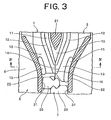
- Entrance end portions of the insertion leg portions 13 of the top end stop 1 can be brought into a firm contact with each other as shown in FIG. 3 to form passage portions 14 which allow the diamond 21 to pass through easily.
- the protrusions 12 are formed so as to end at the passage portions 14, and the passage portions 14 and the edges of the fastener tapes 5 are formed on an identical plane.
- inclined faces 16 are formed by cutting portions facing entrances of the protrusions 12, namely, corners of surfaces on a side adjacent to the fastener elements 7 to provide with slopes. A provision of the inclined faces 16 reduces an impact on the upper and lower blades 20, thereby making the diamond 21 to pass through smoothly.
- Pressing portions 15 are provided on part of right and left outer sides of the entrance end portions of the insertion leg portions 13 of the top end stop 1 such that the pressing portions 15 are projected outward with respect to outer edges of the insertion leg portions 13 while they are projected toward the blades 20 from upper and bottom surfaces of the insertion leg portions 13.
- the pressing portions 15 are projected outward with respect to outer side faces, namely, the contact faces 31 of the leg portion 29 in the fastener element 7 molded as shown in FIGS. 3 and 6.
- a width of the top end stop 1 is formed narrower than a gap between the flanges 22 of the slider 2 as shown in FIG. 3 so that the flanges 22 and the insertion leg portions 13 do contact each other in order to slide the slider 2 smoothly. That is, the insertion leg portions 13 not making contact with the flanges 22 are formed inside outside positions of the top end stop 1 corresponding to the passage portions 14 which keep contact, while the pressing portions 15 are formed at least at each position corresponding to the passage portions 14. In otherwords, the pressing portions 15 are formed at least in a same length as those of the protrusions 12 facing the passage portions 14.
- the pressing portions 15 are formed longer than the protrusions 12 and in a same length as or longer than the passage portions 14.
- a recession is provided between the protrusions 12 formed around the accommodating portion 10 and the pressing portions 15 in the insertion leg portions 13 of the top end stop 1. Consequently, the slider 2 can slide smoothly and lightly because of a partial contact by the blades 20 of the slider 2.
- the right and left end portions at the entrances of the insertion leg portions 13 are shifted to each other corresponding to an arrangement of the fastener elements 7, right and left end portions of the protrusions 12 meet each other.
- Stoppers 17 are projected from the front and rear surfaces as shown in FIG. 9 at the closed front end of the top end stop 1 such that the stoppers 17 meet outer edges of shoulder mouths of head portions 23 of the upper and lower blades 20 of the slider 2 and can make contact therewith, as shown in FIG. 2. Consequently, the head portions 23 of the blades 20 of the slider 2 are brought into an aggressive contact with the stoppers 17 to stop the sliding of the slider 2.
- the base fabrics 4 outside the stoppers 17 are lined with a seal material 8 made of thermoplastic elastomer in order to secure waterproof property.
- this top end stop 1 A use condition of this top end stop 1 will be described hereinafter.
- the diamond 21 pushes and opens the passage portions 14 of the top end stop 1 having elasticity, and the head portions 23 of the blades 20 of the slider 2 make contact with the stoppers 17 while the diamond 21 is accommodated in the accommodating portion 10. Consequently, the flanges 22 of the slider 2 push the right and left pressing portions 15 to bring the passage portions 14 into a pressure contact with each other.
- the protrusions 12 of the top end stop 1 make a pressure contact with the inner faces of the blades 20 of the slider 2, thereby maintaining waterproof and airproof properties at terminals of the base fabrics 4.
- the slider 2 is slid in a direction of departing from the top end stop 1 to push apart the passage portions 14 of the insertion leg portions 13 by means of the diamond 21, thereby allowing the slider 2 to slide.
- FIGS. 7 and 8 show a modification of the waterproof top end stop according to the first embodiment.
- inclined portions are formed at least at the pressing portions 15 and the insertion leg portions 13 on a side of the fastener elements 7 of the fastener tapes 5.
- the inclined portions are formed in a inclined plane shape in which thickness thereof is reduced toward an outside of the top end stop 1.
- a waterproof top end stop according to a second embodiment shown in FIG. 10 is different from the first embodiment in that a pressing portions 15 provided on outer edges of insertion leg portions 13 of the top end stop 1 are flat and not projected upward/downward.
- the top end stop 1 formed of thermoplastic elastomer has an accommodating portion 10 for accommodating a diamond 21, and protrusions 12 projecting upward/downward along an inner peripheral edge portion 11 of the accommodating portion 10 are provided on front and rear faces so that they can make a pressure contact with inner faces of blades 20.
- the pressing portions 15 are formed on the outer edges of the right and left insertion leg portions 13 such that they are swollen slightly from outer faces of the insertion leg portions 13.
- the pressing portions 15 are formed in a same thickness as the insertion leg portions 13 existing on the front and rear faces of the top end stop 1, and makes a sliding contact with inner faces of flanges 22 of the slider 2.
- the pressing portions 15 formed on the outer edges of the insertion leg portions 13 of the top end stop 1 are pressed by the flanges 22 of the slider 2, so that the insertion leg portions 13 are pushed inward to bring passage portions 14 into a pressure contact with each other.
- the protrusions 12 provided along the inner peripheral portion 11 of the accommodating portion 10 make a pressure contact with the inner faces of the blades 20 of the slider 2, and the passage portions 14 are brought into a firm contact with each other by the flanges 22 of the slider 2. Consequently, the top end stop 1 has a waterproof function.
- top end stops of the first and second embodiments described above are not restricted to an injection type fastener element but may be applied to a fastener chain having a coil-like fastener element or a zigzag-like fastener element formed of synthetic resin mono-filament.
- contact faces of each leg portion of each fastener element refers to an inverted portion on an opposite side to a coupling head continuous from upper and lower leg portions of the coil-like or zigzag-like fastener element, namely, an outside of a connecting portion, meaning a portion which makes contact with flanges of a sliding slider.
- the waterproof top end stop for a slide fastener of the present invention is used in an opening portion of a variety of wet suits and waterproof trousers and an opening portion of waterproof shoe for underwater operation, located under water when used, and in an opening portion of a bag, ensuring waterproof and airproof properties.
Landscapes
- Slide Fasteners (AREA)
Abstract
Description
- The present invention relates to a waterproof top end stop for a slide fastener for use in an opening/closing mouth of wet suit, waterproof trousers, waterproof shoes for use underwater, and the like.
- A conventionally known waterproof
top end stop 101 for a slide fastener disclosed by aJapanese Utility Model Application Publication No. 4-36659 accommodation hole 110 capable of accommodating adiamond 121 in aslider 102 provided in its center;passage portions 114 in which thediamond 121 can be inserted and which can be closed firmly, thepassage portions 114 leading to theaccommodation hole 110; an inner sealing portion 111, 113 having a large thickness capable of surrounding theaccommodation hole 110 and thepassage portions 114; and a rib-like seal 112 which is projected from a surface of the inner sealing portion 111, 113 throughout theaccommodation hole 110 and thepassage portions 114, the rib-like seal 112 being entirely formed in a racket-like shape and capable of making a firm contact with inner faces of upper andlower blades 120 of theslider 102. - In the waterproof
top end stop 101 for a slide fastener shown in FIG. 11, its inner sealing portion 111, 113 having a large thickness capable of burying an inside of a body of theslider 102 is formed entirely to be long longitudinally. A rib-like seal 112 which makes a contact with upper andlower blades 120 of theslider 102 formed on the inner sealing portion 111, 113 needs to be projected in a form of a racket into both theaccommodation hole 110 and thepassage portions 114. Accordingly, this structure is not so preferable from viewpoints of waterproof and airproof because the rib-like seal 112 is provided for a long distance. Further, in thistop end stop 101,flanges 122 of theslider 102 are brought into a firm contact with thepassage portions 114 including adiamond 121 when theslider 102 is pulled up in order to seal thepassage portions 114 formed within the inner sealing portion 111, 113. According to this structure, side faces of thepassage portions 114 are just brought into contact with each other by theflanges 122 of theslider 102. Thus, there is such a problem that water may penetrate or invade through thepassage portions 114 because side faces of thepassage portions 114 are only joined together. - The present invention has been achieved in view of the above-described problem, and a first object of the invention is to provide a waterproof top end stop for a slide fastener, in which a protrusion which makes contact with an inner face of each of upper and lower blades of a slider, namely, rib-like seal is formed as short as possible to raise waterproof and airproof properties, and pressing portions for positively pressing an outer side face of the top end stop are formed so as to bring contact faces of insertion leg portions, namely, contact portions of a diamond passage portions into a firm contact with each other by forming the contact portions as short as possible, thereby securing waterproof and airproof effects.
- In addition to the first object, a second object of the invention is to provide a waterproof top end stop for a slide fastener, in which the pressing portions are provided on outer edge portions of insertion leg portions corresponding to the passage portions to close the passage portions accurately and smoothly, thereby raising waterproof and airproof effects.
- In addition to the first object, a third object of the invention is to provide a waterproof top end stop for a slide fastener, in which a relation among the pressing portions installed on the insertion leg portions of the top end stop, the outer edge portions located inside the pressing portions and a slider which accommodates these pressing portions and outer edge portions is specified so as to raise waterproof and airproof effects effectively and accurately.
- In addition to the first object, fourth and fifth objects of the invention are to provide a waterproof top end stop for a slide fastener, in which a configuration of the pressing portions which are formed on both outer sides of the insertion leg portions of the top end stop and make contact with flanges of the slider is specified so as to bring the contact portions of the insertion leg portions into an aggressive contact with each other effectively and accurately, thereby raising the waterproof and airproof effects.
- In addition to the fourth object, a sixth object of the invention is to provide a waterproof top end stop for a slide fastener, in which the insertion leg portions are brought into a partial contact with the blades of the slider through the protrusion and pressing portions, thereby achieving smooth and light sliding of the slider.
- In order to achieve the above-described object, according to a first aspect of the invention, there is provided a waterproof top end stop for a slide fastener having elasticity, which is fixed adjacent to fastener elements provided along opposing side edges of a pair of fastener tapes in a slide fastener and which is connected to the fastener tapes, wherein an accommodating portion capable of accommodating a diamond of a sliding slider is provided in a center thereof such that the accommodating portion is surrounded by insertion leg portions; protrusions which make contact with upper and lower blades of the slider are provided projectingly along an inner
peripheral edge portion 11 provided on an inner edge of the accommodating portion; passage portions which allow the diamond of the slider to pass through is provided at end portions on inner sides of the insertion leg portions; and pressing portions projecting with respect to a contact faces of leg portions in the fastener elements adjacent to the top end stop or a faces making a sliding contact with the slider are provided on both outer sides of the top end stop, namely, outside the insertion leg portions. The pressing portions can be pressed inward when the slider is slid. Due to contact between the pressing portion and the slider, the passage portions are closed firmly. - According to a second aspect of the invention, in addition to the first aspect, there is provided a waterproof top end stop for a slide fastener, wherein the pressing portions installed in the top end stop are formed at positions corresponding to the passage portions which allow the diamond of the slider to pass through, that is, on outer edge portions of the insertion leg portions.
- According to a third aspect of the invention, in addition to the first aspect, there is provided a waterproof top end stop for a slide fastener, wherein the pressing portions installed in the top end stop are provided on the outer edge portions on a side of an entrance of the insertion leg portions, and the outer edge portions provided inside of the top end stop from the pressing portions are formed narrower than an interval between right and left flanges of the slider to avoid making contact with the flanges.
- According to a fourth aspect of the invention, in addition to the first aspect, there is provided a waterproof top end stop for a slide fastener, wherein the pressing portions installed in the top end stop are formed to project in up and down directions from the insertion leg portions.
- According to a fifth aspect of the invention, in addition to the first aspect, there is provided a waterproof top end stop for a slide fastener, wherein the pressing portions installed in the top end stop are formed to project in an outward direction from the insertion leg portions.
- According to a sixth aspect of the invention, in addition to the fourth aspect, there is provided a waterproof top end stop for a slide fastener, wherein the protrusions and pressing portions provided on the insertion leg portions of the top end stop project in up and down directions while a portion between the protrusions and pressing portions is recessed.
- Advantages of the present invention will be described below.
- According to the first aspect of the invention, even when the passage portions which allow the diamond of the slider to pass through are formed with short small contact faces, the pressing portions provided on both outer sides of the top end stop press the insertion leg portions inward aggressively so as to block water from penetrating or invading. Further, even if the protrusions making contact with the inner faces of blades of the slider is formed in a short length along the inner peripheral edge portion of the accommodating portion, waterproof and airproof properties can be exerted effectively, and moreover, the top end stop can be formed easily.
- According to the second aspect of the invention, the passage portions provided inside the insertion leg portions is pressed and closed accurately to block penetration and invasion of water through the passage portions, thereby enhancing waterproof and airproof properties.
- According to the third aspect of the invention, the pressing portions provided on the side of an entrance of the insertion leg portions are pressed inward by a sliding operation while inside portions, that is, deep sides relative to the pressing portions do not make contact with the flanges. Consequently, the sliding operation of the slider can be carried out lightly.
- According to the fourth and fifth aspects of the invention, the pressing portions provided on the insertion leg portions can be brought into a sliding contact with the flanges of the slider securely, so that the passage portions provided inside the insertion leg portions can be pressed and closed securely. Consequently, extremely favorable waterproof and airproof effects are achieved.
- According to the sixth aspect of the invention, the insertion leg portions make a partial contact with the inner faces of the upper and lower blades of the slider, so that the slider can be slid smoothly and lightly. Therefore, the advantages realized by the present invention are remarkable.
-
- FIG. 1 is a perspective view of a waterproof top end stop for a slider fastener;
- FIG. 2 is a partially broken front view of a slider, showing a use condition of the waterproof top end stop;
- FIG. 3 is an enlarged front view of the top end stop of FIG. 2;
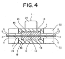
- FIG. 4 is a sectional view of the top end stop taken along a line IV-IV in FIG. 3;
- FIG. 5 is a front view showing the use condition of the top end stop;
- FIG. 6 is an enlarged view of major portions indicating a relation between a pressing portion of the top end stop and a fastener element;
- FIG. 7 is a perspective view of a modification of the top end stop;
- FIG. 8 is a sectional view of the modification of the top end stop taken along a line VIII-VIII in FIG. 7;
- FIG. 9 is a side view showing a state in which a slider is brought into a sliding contact with the top end stop;
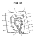
- FIG. 10 is a perspective view of another top end stop; and
- FIG. 11 is a front view showing a use condition of a known top end stop.
- As regards a waterproof top end stop for a slide fastener of the present invention, as shown in FIGS. 1 and 5, surfaces of a pair of
fastener tapes 5 are coated with awaterproof material 6 such as thermoplastic elastomer composed of vinyl chloride or polyethylene or synthetic rubber to formbase fabrics 4.Fastener elements 7 composed of thermoplastic resin such as polyamide or polyacetal are formed on side edges of thebase fabrics 4 by injection molding. Atop end stop 1 is formed at an end portion having thefastener elements 7 attached, the top end stop being composed of the same material as the aforementionedwaterproof material 6 and having elasticity in order to stop aslider 2. - The
top end stop 1 has one end closed. Thetop end stop 1 includes anaccommodating portion 10 capable of accommodating adiamond 21 of theslider 2 provided in a center thereof, andinsertion leg portions 13 formed on right and left sides of the other end such that they are adjacent to thefastener elements 7. Passageportions 14 which allow thediamond 21 of theslider 2 to pass through are formed at sides of entrance end portions of theinsertion leg portions 13, namely, on sides of theinsertion leg portions 13 adjacent to thefastener elements 7. Thepassage portions 14 are constructed such that right andleft passage portions 14 join together to secure waterproof property when a fastener chain is closed with theslider 2. - Pressing
portions 15 are provided by projecting right and left outer sides of theinsertion leg portions 13 slightly outward with respect to outside edges of thefastener elements 7, so that thepressing portions 15 are projected in up and down directions while making contact withflanges 22 of theslider 2.Protrusions 12 are provided so as to be projected toward inner faces of upper andlower blades 20 of theslider 2 to make contact therewith along an innerperipheral edge portion 11 of theaccommodating portion 10 which accommodates thediamond 21. Entrance end portions of theprotrusions 12 face thepassage portions 14 of theinsertion leg portions 13, and end portions of the protrusions are cut out obliquely to forminclined faces 16, thereby reducing an impact on the upper andlower blades 20 to facilitate passage of thediamond 21 when it is inserted.Stoppers 17 are provided protrudedly on both closed end faces of thetop end stop 1 so that head portions 23 of theblades 20 of theslider 2 can make contact with, thereby accommodating theslider 2 accurately in theaccommodating portion 10. - In the meantime, back faces of the
base fabrics 4 outside the closedstoppers 17 of thetop end stop 1 are lined with aseal material 8 to integrate the right andleft fastener tapes 5. - As regards a relation between the
top end stop 1 and theslider 2, waterproof and airproof properties are exerted in such a manner that thediamond 21 is accommodated in theaccommodating portion 10 of thetop end stop 1 by sliding theslider 2, so that thetop end stop 1 is used as a waterproof top end stop. At this time, when thetop end stop 1 accommodates thediamond 21 of theslider 2 in theaccommodating portion 10, theprotrusions 12 provided along the innerperipheral edge portion 11 of theaccommodating portion 10 make a pressure contact with inner faces of theblades 20 as shown in FIG. 4, so that upper and lower faces of thetop end stop 1 are closed firmly with inner faces of theslider 2. Regarding a sealing function of thepassage portions 14 which allow thediamond 21 to pass through, thepassage portion 14 being formed in theinsertion leg portions 13 of thetop end stop 1, as shown in FIGS. 3 and 4, thepressing portions 15 formed in the right and leftinsertion leg portions 13 are pressed inward by theflanges 22 so as to bring thepassage portions 14 into a firm contact with each other from right and left. Therefore, the waterproof and airproof effects of thetop end stop 1 are exerted by bringing theprotrusions 12 and theblades 20 into a pressure contact and pressing thepressing portions 15 inward by theflanges 22, so as to seal thepassage portions 14. - In a waterproof top end stop according to a first embodiment shown in FIGS. 1 to 9, front and rear surfaces of a pair of
fastener tapes 5 are coated with awaterproof material 6 of thermoplastic elastomer such as vinyl chloride or polyethylene or synthetic rubber so as to form abase fabrics 4. Then,fastener elements 7 are formed on opposing side edges of thebase fabrics 4 by injection-molding using thermoplastic resin such as polyamide, polyacetal, polypropylene and polybutylene terephthalate. Each of thefastener elements 7 is formed of mainly acoupling head 28 and aleg portion 29. Theleg portion 29 is formed of a square body while acontact face 31 is formed at an outer end of theleg portion 29 such thatflanges 22 of aslider 2 makes a sliding contact therewith.Fin portions 30 in a flat shape are provided on the contact face 31at a side of one of thefastener tapes 5, and theflanges 22 of theslider 2 makes contact with thefin portions 30 and thecontact face 31 when the slider slides. - The
coupling head 28 is projected from theleg portion 29 in a form of anumber 8, and engagingpieces 32 which are in a flat shape and flush with the edge of thefastener tape 5 are provided on theleg portion 29 at a side of thehead portion 28 and fitted to aconcave groove 33 provided in thecoupling head 28 of a mating fastener element. Therefore, theconcave groove 33 is formed in a front end of thecoupling head 28, so that the engagingpieces 32 projected from both sides of thefastener element 7 of the mating fastener element are accommodated to engage the right and leftfastener elements 7 with each other. - The upper and
lower blades 20 of theslider 2 are joined with thediamond 21, and theflanges 22 for guiding thefastener elements 7 are provided curvedly on both outer sides of theblades 20. By sliding thisslider 2 in back and forth directions, thefastener elements 7 molded on the side edges of thebase fabrics 4 are brought into firm contact with each other both in back and forth directions and in right and left directions so as to provide the right and leftbase fabric 4 with waterproof property. - A
top end stop 1 is injection-molded with the same material as the thermoplastic elastomer such as vinyl chloride or polyethylene or synthetic rubber applied to the surfaces of thebase fabrics 4. In thetop end stop 1, theaccommodating portion 10 capable of accommodating thediamond 21 of theslider 2 is formed in the center with a front end thereof closed such that it is continuous to thefastener elements 7 attached to the side edges of thebase fabrics 4, andinsertion leg portions 13 are provided integrally on right and left sides of theaccommodating portion 10. As shown in FIG. 2, thetop end stop 1 further includes theprotrusions 12 which is accommodated within the right and leftflanges 22 of theslider 2 and provided projectingly toward a surface along the innerperipheral edge portion 11 of theaccommodating portion 10 in the center thereof. Theprotrusions 12 are constructed to make contact with the inner faces of the upper andlower blades 20 of theslider 2 to ensure waterproof performance. Forming of theprotrusions 12 along the innerperipheral edge portion 11 means forming of theprotrusions 12 at a predetermined distance from the innerperipheral edge portion 11 along a contour of the innerperipheral edge portion 11 or forming of theprotrusions 12 on a same plane as the innerperipheral edge portion 11. That is, theprotrusions 12 are formed so as to surround thediamond 21 together with theaccommodating portion 10. - Entrance end portions of the
insertion leg portions 13 of thetop end stop 1 can be brought into a firm contact with each other as shown in FIG. 3 to formpassage portions 14 which allow thediamond 21 to pass through easily. Theprotrusions 12 are formed so as to end at thepassage portions 14, and thepassage portions 14 and the edges of thefastener tapes 5 are formed on an identical plane. Then, inclined faces 16 are formed by cutting portions facing entrances of theprotrusions 12, namely, corners of surfaces on a side adjacent to thefastener elements 7 to provide with slopes. A provision of the inclined faces 16 reduces an impact on the upper andlower blades 20, thereby making thediamond 21 to pass through smoothly. - Pressing
portions 15 are provided on part of right and left outer sides of the entrance end portions of theinsertion leg portions 13 of thetop end stop 1 such that thepressing portions 15 are projected outward with respect to outer edges of theinsertion leg portions 13 while they are projected toward theblades 20 from upper and bottom surfaces of theinsertion leg portions 13. Thepressing portions 15 are projected outward with respect to outer side faces, namely, the contact faces 31 of theleg portion 29 in thefastener element 7 molded as shown in FIGS. 3 and 6. When theslider 2 is slid up to a terminal end, there is generated a gap between theflanges 22 of theslider 2 and the contact faces 31 of theleg portion 29. However, no gap exists between theflanges 22 of theslider 2 and thepressing portions 15 molded on the outer side edges of theinsertion leg portions 13 of thetop end stop 1 so that they make firm contact with each other. Consequently, thepressing portions 15 are pressed inward by theflanges 22, so that thepassage portions 14 are closed firmly. If speaking further, a dimension of a width from the outer sides of thepressing portions 15 to the edge portions of thefastener tapes 5 is larger than a dimension of a width from the contact faces 31 of theleg portion 29 to the end portions of thefastener tapes 5. Since thepressing portions 15 project toward theblades 20, contact areas between thepressing portions 15 andflanges 22 can be increased. - On an inner side or deep side relative to the
pressing portions 15 formed on theinsertion leg portions 13, a width of thetop end stop 1 is formed narrower than a gap between theflanges 22 of theslider 2 as shown in FIG. 3 so that theflanges 22 and theinsertion leg portions 13 do contact each other in order to slide theslider 2 smoothly. That is, theinsertion leg portions 13 not making contact with theflanges 22 are formed inside outside positions of thetop end stop 1 corresponding to thepassage portions 14 which keep contact, while thepressing portions 15 are formed at least at each position corresponding to thepassage portions 14. In otherwords, thepressing portions 15 are formed at least in a same length as those of theprotrusions 12 facing thepassage portions 14. Preferably, thepressing portions 15 are formed longer than theprotrusions 12 and in a same length as or longer than thepassage portions 14. A recession is provided between theprotrusions 12 formed around theaccommodating portion 10 and thepressing portions 15 in theinsertion leg portions 13 of thetop end stop 1. Consequently, theslider 2 can slide smoothly and lightly because of a partial contact by theblades 20 of theslider 2. In the meantime, although the right and left end portions at the entrances of theinsertion leg portions 13 are shifted to each other corresponding to an arrangement of thefastener elements 7, right and left end portions of theprotrusions 12 meet each other. -
Stoppers 17 are projected from the front and rear surfaces as shown in FIG. 9 at the closed front end of thetop end stop 1 such that thestoppers 17 meet outer edges of shoulder mouths of head portions 23 of the upper andlower blades 20 of theslider 2 and can make contact therewith, as shown in FIG. 2. Consequently, the head portions 23 of theblades 20 of theslider 2 are brought into an aggressive contact with thestoppers 17 to stop the sliding of theslider 2. Thebase fabrics 4 outside thestoppers 17 are lined with aseal material 8 made of thermoplastic elastomer in order to secure waterproof property. - A use condition of this
top end stop 1 will be described hereinafter. When theslider 2 mounted on the right and leftbase fabrics 4 is slid toward thetop end stop 1 as shown in FIG. 5, thediamond 21 pushes and opens thepassage portions 14 of thetop end stop 1 having elasticity, and the head portions 23 of theblades 20 of theslider 2 make contact with thestoppers 17 while thediamond 21 is accommodated in theaccommodating portion 10. Consequently, theflanges 22 of theslider 2 push the right and leftpressing portions 15 to bring thepassage portions 14 into a pressure contact with each other. In addition, theprotrusions 12 of thetop end stop 1 make a pressure contact with the inner faces of theblades 20 of theslider 2, thereby maintaining waterproof and airproof properties at terminals of thebase fabrics 4. - To release the waterproof and airproof properties, the
slider 2 is slid in a direction of departing from thetop end stop 1 to push apart thepassage portions 14 of theinsertion leg portions 13 by means of thediamond 21, thereby allowing theslider 2 to slide. - FIGS. 7 and 8 show a modification of the waterproof top end stop according to the first embodiment. In a peripheral portion of the
top end stop 1, inclined portions are formed at least at thepressing portions 15 and theinsertion leg portions 13 on a side of thefastener elements 7 of thefastener tapes 5. As shown in a cross sectional view in FIG. 8, the inclined portions are formed in a inclined plane shape in which thickness thereof is reduced toward an outside of thetop end stop 1. With this feature, thetop end stop 1 is not easily caught even if someone intentionally tries to peel it off, thereby enabling to provide thetop end stop 1 enduring a long-term use. - A waterproof top end stop according to a second embodiment shown in FIG. 10 is different from the first embodiment in that a
pressing portions 15 provided on outer edges ofinsertion leg portions 13 of thetop end stop 1 are flat and not projected upward/downward. If speaking in detail, thetop end stop 1 formed of thermoplastic elastomer has anaccommodating portion 10 for accommodating adiamond 21, andprotrusions 12 projecting upward/downward along an innerperipheral edge portion 11 of theaccommodating portion 10 are provided on front and rear faces so that they can make a pressure contact with inner faces ofblades 20. Then, thepressing portions 15 are formed on the outer edges of the right and leftinsertion leg portions 13 such that they are swollen slightly from outer faces of theinsertion leg portions 13. Thepressing portions 15 are formed in a same thickness as theinsertion leg portions 13 existing on the front and rear faces of thetop end stop 1, and makes a sliding contact with inner faces offlanges 22 of theslider 2. - When the
slider 2 is slid toward thetop end stop 1, thepressing portions 15 formed on the outer edges of theinsertion leg portions 13 of thetop end stop 1 are pressed by theflanges 22 of theslider 2, so that theinsertion leg portions 13 are pushed inward to bringpassage portions 14 into a pressure contact with each other. In thistop end stop 1, theprotrusions 12 provided along the innerperipheral portion 11 of theaccommodating portion 10 make a pressure contact with the inner faces of theblades 20 of theslider 2, and thepassage portions 14 are brought into a firm contact with each other by theflanges 22 of theslider 2. Consequently, thetop end stop 1 has a waterproof function. - The top end stops of the first and second embodiments described above are not restricted to an injection type fastener element but may be applied to a fastener chain having a coil-like fastener element or a zigzag-like fastener element formed of synthetic resin mono-filament. In such a case, contact faces of each leg portion of each fastener element refers to an inverted portion on an opposite side to a coupling head continuous from upper and lower leg portions of the coil-like or zigzag-like fastener element, namely, an outside of a connecting portion, meaning a portion which makes contact with flanges of a sliding slider.
- The waterproof top end stop for a slide fastener of the present invention is used in an opening portion of a variety of wet suits and waterproof trousers and an opening portion of waterproof shoe for underwater operation, located under water when used, and in an opening portion of a bag, ensuring waterproof and airproof properties.
Claims (6)
- A waterproof top end stop (1) for a slide fastener having elasticity, which is disposed adjacent to fastener elements (7) provided along opposing side edges of a pair of fastener tapes (5) to connect the fastener tapes (5), being characterized by comprising:an accommodating portion (10) for accommodating a diamond (21) of a slider (2), the accommodating portion being surrounded by insertion leg portions (13) and provided in a center of the top end stop (1);protrusions (12) which make contact with upper and lower blades (20) of the slider (2), the protrusions being provided along an inner peripheral edge portion (11) of the accommodating portion (10);passage portions (14) which allows the diamond (21) to pass through, the passage portions being provided at ends of the insertion leg portions (13); andpressing portions (15) which are projected more with respect to contact faces (31) of leg portions (29) in the fastener elements (7) adjacent to both outer sides of the top end stop (1), the passage portions (14) being constructed so as to be closed firmly due to contact between the pressing portion (15) and the slider (2).
- The waterproof top end stop for a slide fastener according to claim 1, being characterized in that the pressing portions (15) are disposed at least on outer edge portions of the insertion leg portions (13) corresponding to the passage portions (14).
- The waterproof top end stop for a slide fastener according to claim 1, being characterized in that the pressing portions (15) are provided on the outer edge portions on a side of an entrance of the insertion leg portions (13), and
the outer edge portions inside the pressing portions (15) are formed narrower than an interval between flanges (22) of the slider (2) such that the outer edge portions do not make contact with the flanges (22). - The waterproof top end stop for a slide fastener according to claim 1, being characterized in that the pressing portions (15) are formed to project in up and down directions from the insertion leg portions (13).
- The waterproof top end stop for a slide fastener according to claim 1, being characterized in that the pressing portions (15) are formed to project in an outward direction from the insertion leg portions (13).
- The waterproof top end stop for a slide fastener according to claim 4, being characterized in that the insertion leg portions (13) are formed to be recessed between the protrusions (12) and the pressing portions (15), the protrusions (12) and the pressing
portions (15) projecting in up and down direction.
Applications Claiming Priority (1)
| Application Number | Priority Date | Filing Date | Title |
|---|---|---|---|
| JP2005284939A JP4628233B2 (en) | 2005-09-29 | 2005-09-29 | Top stopper for waterproofing of slide fastener |
Publications (2)
| Publication Number | Publication Date |
|---|---|
| EP1769695A1 true EP1769695A1 (en) | 2007-04-04 |
| EP1769695B1 EP1769695B1 (en) | 2009-11-18 |
Family
ID=37649494
Family Applications (1)
| Application Number | Title | Priority Date | Filing Date |
|---|---|---|---|
| EP06254906A Active EP1769695B1 (en) | 2005-09-29 | 2006-09-22 | Waterproof top end stop of slide fastener |
Country Status (10)
| Country | Link |
|---|---|
| US (1) | US7591051B2 (en) |
| EP (1) | EP1769695B1 (en) |
| JP (1) | JP4628233B2 (en) |
| KR (1) | KR100732584B1 (en) |
| CN (1) | CN1939180B (en) |
| AU (1) | AU2006207857B2 (en) |
| CA (1) | CA2558945C (en) |
| DE (1) | DE602006010496D1 (en) |
| ES (1) | ES2334515T3 (en) |
| TW (1) | TWI314849B (en) |
Cited By (2)
| Publication number | Priority date | Publication date | Assignee | Title |
|---|---|---|---|---|
| WO2007087802A3 (en) * | 2006-02-03 | 2007-11-29 | Hartmut Ortlieb | Sealing zipper |
| EP1992243A1 (en) * | 2007-05-16 | 2008-11-19 | Riri Group S.A. | Fluid-tight slide fastener |
Families Citing this family (39)
| Publication number | Priority date | Publication date | Assignee | Title |
|---|---|---|---|---|
| JP4628233B2 (en) * | 2005-09-29 | 2011-02-09 | Ykk株式会社 | Top stopper for waterproofing of slide fastener |
| EP1908364A1 (en) * | 2006-10-04 | 2008-04-09 | Riri Group S.A. | A fluid-tight slide fastener |
| DE602007011071D1 (en) * | 2007-10-04 | 2011-01-20 | Riri Sa | Fluid-tight zipper |
| CN101754629B (en) * | 2008-12-19 | 2012-08-29 | 群康科技(深圳)有限公司 | Circuit board fixing structure |
| CA2747818C (en) * | 2008-12-22 | 2015-07-21 | Columbia Sportswear North America, Inc. | Weather resistant slide fasteners |
| US8375528B2 (en) | 2009-12-01 | 2013-02-19 | Ykk Corporation | Water repellent slider cap for zippers |
| WO2011089588A1 (en) * | 2010-01-24 | 2011-07-28 | Paskal Zippers Ltd. | A waterproof zipper and manufacturing method therefor |
| DE112011101280T5 (en) | 2010-04-09 | 2013-05-08 | Lion Apparel, Inc. | Steam-tight closure |
| CA2839000C (en) | 2011-06-13 | 2020-03-24 | Cleanbrands, Llc | Protective barrier for a zipper assembly |
| WO2013013007A1 (en) * | 2011-07-20 | 2013-01-24 | Ykk Corporation | Top stop for slider |
| KR101331733B1 (en) * | 2011-08-16 | 2013-11-20 | 이병우 | Pest-resistant protection unit and zipper device |
| DE112012005786B4 (en) * | 2012-01-30 | 2019-01-31 | Ykk Corp. | Waterproof zipper |
| CN104168793B (en) * | 2012-03-14 | 2017-05-24 | Ykk株式会社 | Waterproof slide fastener and waterproof product |
| US9138033B2 (en) * | 2013-03-14 | 2015-09-22 | Ykk Corporation | Top stop for slider |
| GB201311761D0 (en) | 2013-07-01 | 2013-08-14 | Raw Ip Ltd | A zip fastener |
| US10251455B2 (en) * | 2013-07-25 | 2019-04-09 | Zhejiang Weixing Industrial Development Co., Ltd. | Square for zipper and zipper |
| WO2016027310A1 (en) * | 2014-08-19 | 2016-02-25 | Ykk株式会社 | Stopper for slide fastener |
| US20240324732A1 (en) * | 2014-12-04 | 2024-10-03 | Nite Ize, Inc. | Systems and methods for extruded zippers, zipper garages, connection techniques, and uses therefore |
| CN113633072B (en) * | 2014-12-04 | 2024-01-30 | 特鲁拉链有限责任公司 | System and method for improved zipper slider storage member |
| US11109650B2 (en) | 2014-12-04 | 2021-09-07 | Nite Ize, Inc. | Systems and methods for improved zipper slider garage |
| GB2541891B (en) * | 2015-09-01 | 2018-07-11 | Versapak Int Ltd | Sealing device |
| CN109310186B (en) | 2016-04-14 | 2021-09-07 | 科林博兰兹有限责任公司 | Protective enclosure for zippers |
| CN109788827B (en) * | 2016-10-11 | 2021-09-17 | Ykk株式会社 | Waterproof slide fastener |
| CN206791835U (en) * | 2017-03-30 | 2017-12-26 | 东莞市鼎富拉链科技有限公司 | A waterproof zipper |
| PL3629822T3 (en) * | 2017-06-02 | 2025-11-12 | Mrm Hk Limited | ZIPPER |
| TWI619445B (en) * | 2017-08-07 | 2018-04-01 | 冠宇拉鍊股份有限公司 | Waterproof fastener tape and watertight slide fastener including the same |
| JP3213897U (en) * | 2017-09-26 | 2017-12-07 | Ykk株式会社 | Stopper included in slide fastener |
| US11006680B2 (en) | 2017-10-03 | 2021-05-18 | Lion Group, Inc. | Particulate resistant garment |
| GB2581445B (en) | 2017-10-03 | 2023-07-05 | Lion Group Inc | Particulate resistant garment |
| TWI635821B (en) * | 2017-11-13 | 2018-09-21 | 冠宇拉鍊股份有限公司 | Waterproof zipper |
| JP7001812B2 (en) * | 2018-03-19 | 2022-02-10 | Ykk株式会社 | Slide fastener |
| US10625906B1 (en) * | 2018-11-16 | 2020-04-21 | Stasher, Inc. | Inside out method of manufacturing a container with a leak resistant seal |
| MX2021006694A (en) * | 2018-12-05 | 2021-07-07 | Nite Ize Inc | Systems and methods for improved zipper slider garage. |
| JP7339855B2 (en) * | 2019-11-01 | 2023-09-06 | Ykk株式会社 | Waterproof slide fastener slider and waterproof slide fastener |
| JP2023503233A (en) | 2019-11-23 | 2023-01-27 | タロン テクノロジーズ、インコーポレイティッド | curved zipper |
| US11363860B2 (en) | 2019-11-23 | 2022-06-21 | Talon Technologies, Inc. | Waterproof curved zippers |
| USD1013692S1 (en) | 2020-05-15 | 2024-02-06 | Ugowear, Llc | Tablet carrying device |
| USD1000446S1 (en) | 2020-09-11 | 2023-10-03 | Ugowear, Llc | Protective case |
| CN113712347A (en) * | 2021-09-18 | 2021-11-30 | 晋江市瑞泰拉链制造有限公司 | Waterproof zipper stop and zipper |
Citations (5)
| Publication number | Priority date | Publication date | Assignee | Title |
|---|---|---|---|---|
| US2928156A (en) * | 1957-06-19 | 1960-03-15 | New Zipper Corp | Slide fastener |
| GB834433A (en) * | 1955-08-22 | 1960-05-11 | Goodrich Co B F | Sealing closure end stop and seal |
| EP0095160A1 (en) * | 1982-05-26 | 1983-11-30 | Yoshida Kogyo K.K. | Watertight slide fastener |
| GB2199616A (en) * | 1986-12-26 | 1988-07-13 | Yoshida Kogyo Kk | Top stop for water-tight slide fastener |
| DE202006001891U1 (en) * | 2006-02-03 | 2006-06-01 | Ortlieb, Hartmut | Sealing zipper |
Family Cites Families (10)
| Publication number | Priority date | Publication date | Assignee | Title |
|---|---|---|---|---|
| US2923992A (en) * | 1955-08-15 | 1960-02-09 | Sealing closure | |
| JPH053051Y2 (en) * | 1987-08-14 | 1993-01-26 | ||
| JPH0436659Y2 (en) * | 1987-12-25 | 1992-08-28 | ||
| JPH0436659A (en) | 1990-05-31 | 1992-02-06 | Toshiba Corp | Automatic chemical analysis apparatus |
| JPH051307U (en) * | 1991-06-28 | 1993-01-14 | 吉田工業株式会社 | Watertight slide fastener |
| US5253395A (en) * | 1992-06-26 | 1993-10-19 | Yoshida Kogyo K. K. | Watertight slide fastener |
| JPH06253909A (en) * | 1993-03-10 | 1994-09-13 | Yoshida Kogyo Kk <Ykk> | Watertight airtight slide fastener |
| DE19643861C2 (en) * | 1996-10-30 | 1999-05-20 | Hartmut Ortlieb | Process for making a water and gas tight zipper |
| JP4628233B2 (en) * | 2005-09-29 | 2011-02-09 | Ykk株式会社 | Top stopper for waterproofing of slide fastener |
| US7392572B2 (en) * | 2006-04-03 | 2008-07-01 | Riri Group S.A. | Fluidtight slide fastener |
-
2005
- 2005-09-29 JP JP2005284939A patent/JP4628233B2/en not_active Expired - Lifetime
-
2006
- 2006-09-05 AU AU2006207857A patent/AU2006207857B2/en not_active Ceased
- 2006-09-07 CA CA002558945A patent/CA2558945C/en not_active Expired - Fee Related
- 2006-09-13 TW TW095133886A patent/TWI314849B/en not_active IP Right Cessation
- 2006-09-22 DE DE602006010496T patent/DE602006010496D1/en active Active
- 2006-09-22 EP EP06254906A patent/EP1769695B1/en active Active
- 2006-09-22 ES ES06254906T patent/ES2334515T3/en active Active
- 2006-09-28 US US11/529,101 patent/US7591051B2/en active Active
- 2006-09-28 CN CN2006101396957A patent/CN1939180B/en active Active
- 2006-09-28 KR KR1020060094456A patent/KR100732584B1/en not_active Expired - Fee Related
Patent Citations (5)
| Publication number | Priority date | Publication date | Assignee | Title |
|---|---|---|---|---|
| GB834433A (en) * | 1955-08-22 | 1960-05-11 | Goodrich Co B F | Sealing closure end stop and seal |
| US2928156A (en) * | 1957-06-19 | 1960-03-15 | New Zipper Corp | Slide fastener |
| EP0095160A1 (en) * | 1982-05-26 | 1983-11-30 | Yoshida Kogyo K.K. | Watertight slide fastener |
| GB2199616A (en) * | 1986-12-26 | 1988-07-13 | Yoshida Kogyo Kk | Top stop for water-tight slide fastener |
| DE202006001891U1 (en) * | 2006-02-03 | 2006-06-01 | Ortlieb, Hartmut | Sealing zipper |
Cited By (3)
| Publication number | Priority date | Publication date | Assignee | Title |
|---|---|---|---|---|
| WO2007087802A3 (en) * | 2006-02-03 | 2007-11-29 | Hartmut Ortlieb | Sealing zipper |
| EP1992243A1 (en) * | 2007-05-16 | 2008-11-19 | Riri Group S.A. | Fluid-tight slide fastener |
| AU2008202126B2 (en) * | 2007-05-16 | 2013-03-14 | Riri Group S.A. | A fluid-tight slide fastener |
Also Published As
| Publication number | Publication date |
|---|---|
| CN1939180A (en) | 2007-04-04 |
| CA2558945A1 (en) | 2007-03-29 |
| JP2007089898A (en) | 2007-04-12 |
| JP4628233B2 (en) | 2011-02-09 |
| US20070067969A1 (en) | 2007-03-29 |
| ES2334515T3 (en) | 2010-03-11 |
| TW200716008A (en) | 2007-05-01 |
| KR100732584B1 (en) | 2007-06-28 |
| CA2558945C (en) | 2009-11-17 |
| EP1769695B1 (en) | 2009-11-18 |
| AU2006207857B2 (en) | 2008-07-03 |
| AU2006207857A1 (en) | 2007-04-19 |
| US7591051B2 (en) | 2009-09-22 |
| TWI314849B (en) | 2009-09-21 |
| CN1939180B (en) | 2010-04-14 |
| HK1103273A1 (en) | 2007-12-14 |
| DE602006010496D1 (en) | 2009-12-31 |
| KR20070036689A (en) | 2007-04-03 |
Similar Documents
| Publication | Publication Date | Title |
|---|---|---|
| US7591051B2 (en) | Waterproof top end stop of slide fastener | |
| CN109788827B (en) | Waterproof slide fastener | |
| EP1800557B1 (en) | Waterproof slide fastener | |
| CN100556330C (en) | Front code for zip | |
| CN101209142A (en) | Zipper top stop | |
| CA1282941C (en) | Fluid-tight slide fastener | |
| US7669296B2 (en) | Slide fastener | |
| EP1430804B1 (en) | Concealed type slide fastener | |
| CN210492911U (en) | Slide fastener | |
| CN113120413A (en) | Zipper assembly and sealing bag | |
| HK1103273B (en) | Waterproof top end stop of slide fastener | |
| CN216293221U (en) | Zipper strip with leakage-proof arc groove teeth and zipper | |
| KR20170038277A (en) | Nwe zipper of easily lock |
Legal Events
| Date | Code | Title | Description |
|---|---|---|---|
| PUAI | Public reference made under article 153(3) epc to a published international application that has entered the european phase |
Free format text: ORIGINAL CODE: 0009012 |
|
| 17P | Request for examination filed |
Effective date: 20060929 |
|
| AK | Designated contracting states |
Kind code of ref document: A1 Designated state(s): AT BE BG CH CY CZ DE DK EE ES FI FR GB GR HU IE IS IT LI LT LU LV MC NL PL PT RO SE SI SK TR |
|
| AX | Request for extension of the european patent |
Extension state: AL BA HR MK YU |
|
| 17Q | First examination report despatched |
Effective date: 20071105 |
|
| AKX | Designation fees paid |
Designated state(s): DE ES FR GB IT |
|
| GRAP | Despatch of communication of intention to grant a patent |
Free format text: ORIGINAL CODE: EPIDOSNIGR1 |
|
| GRAS | Grant fee paid |
Free format text: ORIGINAL CODE: EPIDOSNIGR3 |
|
| GRAA | (expected) grant |
Free format text: ORIGINAL CODE: 0009210 |
|
| AK | Designated contracting states |
Kind code of ref document: B1 Designated state(s): DE ES FR GB IT |
|
| REG | Reference to a national code |
Ref country code: GB Ref legal event code: FG4D |
|
| REF | Corresponds to: |
Ref document number: 602006010496 Country of ref document: DE Date of ref document: 20091231 Kind code of ref document: P |
|
| REG | Reference to a national code |
Ref country code: ES Ref legal event code: FG2A Ref document number: 2334515 Country of ref document: ES Kind code of ref document: T3 |
|
| PLBE | No opposition filed within time limit |
Free format text: ORIGINAL CODE: 0009261 |
|
| STAA | Information on the status of an ep patent application or granted ep patent |
Free format text: STATUS: NO OPPOSITION FILED WITHIN TIME LIMIT |
|
| 26N | No opposition filed |
Effective date: 20100819 |
|
| REG | Reference to a national code |
Ref country code: FR Ref legal event code: PLFP Year of fee payment: 11 |
|
| REG | Reference to a national code |
Ref country code: FR Ref legal event code: PLFP Year of fee payment: 12 |
|
| REG | Reference to a national code |
Ref country code: FR Ref legal event code: PLFP Year of fee payment: 13 |
|
| PGFP | Annual fee paid to national office [announced via postgrant information from national office to epo] |
Ref country code: IT Payment date: 20190917 Year of fee payment: 14 Ref country code: FR Payment date: 20190815 Year of fee payment: 14 |
|
| PGFP | Annual fee paid to national office [announced via postgrant information from national office to epo] |
Ref country code: GB Payment date: 20190920 Year of fee payment: 14 |
|
| PGFP | Annual fee paid to national office [announced via postgrant information from national office to epo] |
Ref country code: ES Payment date: 20191002 Year of fee payment: 14 |
|
| GBPC | Gb: european patent ceased through non-payment of renewal fee |
Effective date: 20200922 |
|
| PG25 | Lapsed in a contracting state [announced via postgrant information from national office to epo] |
Ref country code: FR Free format text: LAPSE BECAUSE OF NON-PAYMENT OF DUE FEES Effective date: 20200930 |
|
| PG25 | Lapsed in a contracting state [announced via postgrant information from national office to epo] |
Ref country code: GB Free format text: LAPSE BECAUSE OF NON-PAYMENT OF DUE FEES Effective date: 20200922 |
|
| REG | Reference to a national code |
Ref country code: ES Ref legal event code: FD2A Effective date: 20220118 |
|
| PG25 | Lapsed in a contracting state [announced via postgrant information from national office to epo] |
Ref country code: IT Free format text: LAPSE BECAUSE OF NON-PAYMENT OF DUE FEES Effective date: 20200922 |
|
| PG25 | Lapsed in a contracting state [announced via postgrant information from national office to epo] |
Ref country code: ES Free format text: LAPSE BECAUSE OF NON-PAYMENT OF DUE FEES Effective date: 20200923 |
|
| P01 | Opt-out of the competence of the unified patent court (upc) registered |
Effective date: 20230428 |
|
| PGFP | Annual fee paid to national office [announced via postgrant information from national office to epo] |
Ref country code: DE Payment date: 20250730 Year of fee payment: 20 |