EP1768098A1 - Image processing device, image processing system, image processing method, computer program, and semiconductor device - Google Patents
Image processing device, image processing system, image processing method, computer program, and semiconductor device Download PDFInfo
- Publication number
- EP1768098A1 EP1768098A1 EP05757913A EP05757913A EP1768098A1 EP 1768098 A1 EP1768098 A1 EP 1768098A1 EP 05757913 A EP05757913 A EP 05757913A EP 05757913 A EP05757913 A EP 05757913A EP 1768098 A1 EP1768098 A1 EP 1768098A1
- Authority
- EP
- European Patent Office
- Prior art keywords
- partial data
- data
- memory
- display memory
- pieces
- Prior art date
- Legal status (The legal status is an assumption and is not a legal conclusion. Google has not performed a legal analysis and makes no representation as to the accuracy of the status listed.)
- Withdrawn
Links
Images









Classifications
-
- G—PHYSICS
- G09—EDUCATION; CRYPTOGRAPHY; DISPLAY; ADVERTISING; SEALS
- G09G—ARRANGEMENTS OR CIRCUITS FOR CONTROL OF INDICATING DEVICES USING STATIC MEANS TO PRESENT VARIABLE INFORMATION
- G09G5/00—Control arrangements or circuits for visual indicators common to cathode-ray tube indicators and other visual indicators
- G09G5/001—Arbitration of resources in a display system, e.g. control of access to frame buffer by video controller and/or main processor
-
- G—PHYSICS
- G09—EDUCATION; CRYPTOGRAPHY; DISPLAY; ADVERTISING; SEALS
- G09G—ARRANGEMENTS OR CIRCUITS FOR CONTROL OF INDICATING DEVICES USING STATIC MEANS TO PRESENT VARIABLE INFORMATION
- G09G5/00—Control arrangements or circuits for visual indicators common to cathode-ray tube indicators and other visual indicators
- G09G5/36—Control arrangements or circuits for visual indicators common to cathode-ray tube indicators and other visual indicators characterised by the display of a graphic pattern, e.g. using an all-points-addressable [APA] memory
- G09G5/39—Control of the bit-mapped memory
- G09G5/399—Control of the bit-mapped memory using two or more bit-mapped memories, the operations of which are switched in time, e.g. ping-pong buffers
Definitions
- the present invention relates to an image processing device whose latency is improved without increasing a storage capacity of a memory used for image processing as much as possible, and to an image processing method executed by the image processing device, an image processing system, and a computer program.
- an graphic image drawn in a frame memory is temporarily saved to a display memory and is outputted to a display unit or the like from the display memory by transforming the graphic image into a video output signal conforming to a standard such as an NTSC system.
- Saving the graphic image from the frame memory allows an image of a next frame to be drawn in the frame memory even when the video output signal is being outputted.
- Saving of the graphic image from the frame memory to the display memory is carried out after a display of a previous frame is finished. Saving from the frame memory to the display memory is carried out during VBI (Vertical Blank Interval).
- VBI Vertical Blank Interval
- the transformation process is carried out on the graphic image that has been saved to the display memory. In this case, the conversion process must also be carried out during the VBI as well as the saving. Because saving and transformation processes that can be carried out during the VBI are limited, a size and definition of a displayable image may be determined by such the limitation. Still more, drawing to the frame memory can only be carried out after finishing the save. Therefore, drawing to the frame memory cannot be carried out asynchronously with the output.
- the display memory has a double-buffer structure.
- the double-buffer structure By using the display memory with the double-buffer structure, it becomes possible to carry out the processes such as saving of a graphic to another display memory and transformation thereof while displaying an image from one display memory on a display unit, so it becomes unnecessary to finish the saving and transformation processes during the VBI.
- drawing and output may be carried out asynchronously because drawing to the frame memory can be carried out immediately after finishing the saving.
- an object of the present invention is to solve the above-mentioned problems and to provide an image processing technique which shortens latency more than the conventional method employing the double-buffer structure, enables the saving and transformation processes to be carried out outside the VBI interval, and enables drawing and output to be carried out asynchronously while suppressing an increase amount of the display memory to the minimum.
- An image processing device of the present invention made to solve the above-mentioned problems includes: image processing means for carrying out predetermined image processing per frame of a moving image, and storing frame data representing an image corresponding to a result of the image processing to a predetermined graphic memory; save processing means for saving the frame data stored in the graphic memory to a predetermined display memory in a unit of partial data of the frame data equally divided; and an output interface for transforming the frame data saved in the display memory into a video output signal in the unit of partial data and outputting the video output signal to the outside.
- the frame data is saved in the display memory as partial data divided into a plurality of parts.
- the frame data is outputted from the display memory not at once but in a unit of partial data.
- the use of the partial data enables the data to be outputted before the entire frame data is saved, so the latency becomes shorter than in the conventional case of employing the double-buffer structure for the display memory.
- the partial data needs to be at least saved before reaching the timing when the partial data is outputted from the display memory. For example, at least partial data outputted right after a VBI interval needs to be saved, so the process for saving the frame data may be carried out even outside the VBI interval. Still more, when a transformation process is carried out on the saved partial data, the saving and transformation processes of other partial data need to at least end before reaching the actual output timing even when exceeding the VBI interval if the saving and transformation processes of the partial data outputted right after the VBI interval have been carried out. Still more, the use of the display memory allows the drawing and output to be carried out asynchronously because drawing to the graphic memory becomes possible if the frame data is saved from the graphic memory to the display memory.
- the save processing means is arranged so as to store pieces of partial data, which are obtained by equally dividing the frame data stored in the graphic memory into a number equal to or less than the number of buffer areas of the display memory and into a data size that can be stored in each of the buffer areas, to the buffer areas whose number corresponds to the number of the pieces of partial data.
- the buffer area may be a storage area logically formed in the memory unit or a storage area formed physically by a plurality of memory units.
- the buffer area may also be formed logically and physically by the plurality of memory units.
- the display memory is provided with the buffer area in a number capable of storing frame data of one frame or more and less than two frames.
- Such configuration allows the storage capacity of the memory used for the display memory to be reduced more than the case of employing the double-buffer structure for the display memory.
- the save processing means is arranged, for example, to be able to confirm states of saving of the partial data from the graphic memory to the display memory and states of output of the partial data stored in the display memory, and to save the partial data from the graphic memory to the display memory in accordance with the output state of the partial data from the display memory.
- Such the image processing device can be arranged so as to carry out the following saving and transformation processes.
- the save processing means is arranged such that the "m" pieces of partial data among frame data of a next frame stored in the graphic memory equally divided into “n” parts are saved to the buffer areas of the display memory from which the pieces of partial data have been outputted, and when remaining pieces of partial data of the same frame data as the partial data previously outputted from the display buffer are outputted in succession, the remaining pieces of partial data from the graphic memory are saved to the buffer areas of the display memory.
- the save processing means is arranged so as to save the frame data stored in the graphic memory to the display memory by equally dividing the frame data into "n” pieces of partial data when the partial data of " (n - 1)" pieces are outputted from the display memory.
- an image processing device may further include image transformation processing means for carrying out a predetermined transformation process on the pieces of partial data saved in the buffer areas of the display memory, and for storing results of the transformation process in the buffer areas in which the pieces of partial data have been stored.
- the display memory is provided with “ (n + 2) ", where "n” is an integer of “2" or more, buffer areas, and pieces of partial data of the frame data equally divided into “n” parts by the save processing means are stored in the “n” buffer areas, when "m", where "m” is an integer represented by “1 m (n - 1) " , pieces of partial data is outputted from the display memory, the save processing means may be arranged such that the "m” pieces of partial data among next frame data equally divided into "n” parts from the graphic memory are saved to the display memory, and when remaining pieces of partial data of the same frame data as the partial data previously outputted from the display buffer are outputted in succession, the remaining pieces of partial data from the graphic memory are saved to the buffer areas of the display memory.
- the image transformation processing means may be arranged so as to carry out the predetermined transformation process on the pieces of partial data saved in the buffer areas, and to store results of the transformation process in the buffer areas except the buffer areas in which the partial data has been saved and in which the pieces of partial data divided from the same frame data as the partial data have been saved.
- an image processing device further includes image transformation processing means for carrying out a predetermined transformation process on the partial data saved in the display memory
- the display memory is provided with "(n + 3)", where "n” is an integer of "2" or more, buffer areas, and pieces of partial data of the frame data equally divided into “n” parts by the save processing means are stored in the "n” buffer areas, when "m", which is an integer represented by "1 m (n - 1)", pieces of partial data are outputted from the display memory
- the save processing means may be arranged such that the partial data from the graphic memory are saved to the display memory, and when remaining pieces of partial data of the same frame data as the partial data previously outputted from the display buffer are outputted in succession, the remaining pieces of partial data from the graphic memory are saved to the buffer areas of the display memory.
- the image transformation processing means may be arranged so as to carry out the predetermined transformation process on one or more pieces of partial data saved in the buffer areas, and to store results of the transformation process in the buffer areas except the buffer areas in which the partial data used for the transformation process has been saved and in which the pieces of partial data divided from the same frame data as the partial data have been saved.
- the display memory is provided with "(n + 2k -1)", where "n” is an integer that satisfies "n > 2k - 1", buffer areas, and pieces of partial data of the frame data equally divided into “n” parts by the save processing means are stored in the "n” buffer areas, when outputs of " (n - 1) " pieces of partial data have ended at a fastest refresh rate, the save processing means may be arranged such that partial data of frame data of a next frame from the graphic memory is saved to the buffer areas except the buffer areas storing the partial data being outputted at another refresh rate and pieces of partial data to be outputted next at respective refresh rates.
- an image processing device including: image processing means for carrying out predetermined image processing per frame of a moving image and storing frame data representing an image corresponding to results of the image processing to a predetermined graphic memory; a display memory provided with "(n + 1)", where "n” is an integer of "2" or more, display buffer areas, for storing the frame data in each of the buffer areas by dividing the frame data; an output memory provided with “ (n - 1) " output buffer areas whose storage capacity is larger than that of the display buffer area; save processing means for saving partial data of the frame data stored in the graphic memory and equally divided into “n” parts to each one of the "n” display buffer areas one by one; image transformation processing means for carrying out a predetermined transformation process on the partial data saved in the display memory to store a result of the processing indicating data whose data size is larger than that of the partial data in the output buffer; and an output interface for outputting the result of the processing stored in the output memory to the outside by transforming the result into a video output signal,
- an image processing system including: image processing means for carrying out predetermined image processing per frame of a moving image, and for storing frame data representing an image corresponding to a result of the image processing to a predetermined graphic memory; a display memory provided with a plurality of buffer areas, for storing the frame data to each of the buffer areas by dividing the frame data; save processing means for saving the frame data stored in the graphic memory to the display memory; and an output interface for transforming the frame data saved in the display memory into video output signals and outputting the signals to the outside, in which: the save processing means is arranged so as to store the frame data stored in the graphic memory by equally dividing the frame data into a plurality of pieces of partial data in a number equal to or less than the number of buffer areas of the display memory and into a data size that can be stored in each of the buffer areas, to the buffer areas whose number corresponds to the number of the pieces of partial data; and the graphic memory and the display memory are provided in different units connected via a network.
- an image processing method executed in a device having save processing means for saving frame data representing an image corresponding to a result of predetermined image processing carried out per frame of a moving image from a graphic memory in which the frame data is stored to a predetermined display memory, and which causes a predetermined display unit to display the frame data saved in the display memory by transforming the frame data into a video output signal, the method comprising the steps of saving, by the save processing means, partial data obtained by equally dividing the frame data from the graphic memory to the display memory in a unit of partial data, and outputting the frame data saved to the display memory in the unit of partial data.
- the method when the display memory has a plurality of buffer areas, the method further comprises generating, by the save processing means, pieces of partial data by equally dividing the frame data stored in the graphic memory in a number equal to or less than the number of buffer areas of the display memory and into a data size that can be stored in each of the buffer areas, and saving, by the save processing means, the pieces of partial data to the buffer areas whose number corresponds to the number of pieces of partial data.
- a computer program according to the present invention is a computer program for a computer that saves frame data representing an image corresponding to a result of predetermined image processing carried out per frame of a moving image from a graphic memory in which the frame data is stored to a predetermined display memory, and which causes a predetermined display unit to display the frame data saved in the display memory by transforming the frame data into a video output signal, the computer program causing the computer to execute a process of saving the partial data obtained by equally dividing the frame data from the graphic memory to the display memory in a unit of partial data, and outputting the frame data saved in the display memory in the unit of partial data.
- a semiconductor device is a semiconductor device that can be mounted in a device for carrying out predetermined image processing per frame of a moving image and displaying an image corresponding to a result of the image processing on a predetermined display unit, including: a graphic memory for storing frame data representing an image corresponding to a result of the image processing; a display memory for storing the frame data equally divided; save processing means for saving the frame data stored in the graphic memory to the display memory per piece of partial data obtained by equally dividing the frame data; and an output interface for transforming the frame data saved in the display memory into a video output signal per piece of partial data and outputting the signal to the display unit.
- Fig. 1 is a diagram showing a hardware configuration of an image processing device of the present invention.
- the image processing device 1 displays an image on a display unit (not shown) and outputs sounds from a speaker or the like by reading and processing programs and data stored in a media 141 such as a CD-ROM or a DVD-ROM.
- a media 141 such as a CD-ROM or a DVD-ROM.
- Such the image processing device 1 may be realized by, for example, a general-purpose computer, a video game machine, an entertainment device, and the like having an image processing function.
- the image processing device 1 is composed of a CPU (Central Processing Unit) 10, a main memory 11 composed of a RAM, a DMAC (Direct Memory Access Controller) 12, an MPEG (Moving Picture Experts Group) decoder (MDEC) 13, a media drive 14 for mounting a media 141, a input section 15, a ROM 16 in which programs such as BIOS are recorded, a sound processing unit (referred to as “SPU” hereinafter) 17 for reading sound data accumulated in a sound memory 171 to output as audio output signal, a graphic processing unit (referred to as "GPU” hereinafter) 18 having a frame memory 19, the frame memory 19 in which images are drawn by the GPU 18, and a CRTC (CRT Controller) 20 for generating a video output signal. These are connected with each other through buses B.
- a CPU Central Processing Unit
- main memory 11 composed of a RAM
- DMAC Direct Memory Access Controller
- MDEC Motion Picture Experts Group decoder
- the video output signal is generated in conformity with standards such as NTSC (National Television Standards Committee) and PAL (Phase Alternation by Line) and is outputted from the CRTC 20 to a display unit.
- standards such as NTSC (National Television Standards Committee) and PAL (Phase Alternation by Line)
- the CPU 10 is a semiconductor device that reads a starting program out of the ROM 16 in starting the image processing device 1, and executes the starting program to operate an operating system.
- the CPU 10 also controls the media drive 14 so as to read an application program out of the media 141 mounted to the media drive 14 and to store the read application program in the main memory 11.
- the CPU 10 further has a function of reading data necessary for generating an image such as 3-D graphic data (such as coordinate values of apexes of a polygon), texture data, and the like composed of a plurality of basic graphics (polygons) out of the media 141, and storing the data in the auxiliary storage unit 19.
- the 3-D graphic data represents an object image in a 3-D image.
- the CPU 10 also has a function of carrying out a geometric process such as coordinate transformation process and perspective transformation process on the 3-D graphic data to generate a display list containing contents of polygon definition information (specification of position, color, texture coordinates, fog color, and the like of the apex and center of gravity of the polygon to be used) obtained by the geometric process.
- a geometric process such as coordinate transformation process and perspective transformation process
- the GPU 18 is a semiconductor device that has a function of generating a graphic image by rendering the polygons in the frame memory 19 by carrying out a rendering process by using the display list.
- the GPU 18 carries out the rendering process by the 3-D graphic data and texture data specified in the display list.
- the image processing device 1 is provided with the CPU 10 and the GPU 18 as separate pieces of hardware, the image processing device 1 may use a processor unit having these functions at the same time.
- the SPU 17 is a semiconductor device for generating an audio output signal by synthesizing sound data read out of the sound memory 171.
- the DMAC 12 is a semiconductor device for carrying out DMA transfer control on each circuit connected to the bus B, and the MDEC 13 is a semiconductor device that operates in parallel with the CPU 10 and has a function of elongating data compressed by the method such as an MPEG (Moving Picture Experts Group) system or a JPEG (Joint Photographic Experts Group) system.
- the input section 15 has a connection terminal 15a to which an input signal from an operating unit 151 is inputted.
- the operating unit 151 is provided with a plurality of operating buttons and an operator can move and deform an object image displayed on the display unit by variously operating these operating buttons.
- a keyboard, a mouse, a controller of a video game machine, and the like may be used as the operating unit 151, for example.
- a graphic image drawn in the frame memory 19 is equally divided and saved in the main memory 11.
- Data of the graphic image drawn in the frame memory 19 is referred to as frame data in this specification.
- the frame data of a first frame will be expressed as first frame data
- the frame data of a second frame will be expressed as second frame data
- the frame data of an n-th frame will be expressed as n-th frame data.
- the data generated by being equally divided will be referred to as partial data in this specification.
- the partial data of the first frame data will be expressed as partial data 1-1, 1-2, 1-3, and 1-4.
- the partial data of the n-th frame data will be expressed as partial data n-1, n-2, n-3, and n-4, respectively.
- the CRTC 20 transforms the saved partial data into a video output signal and outputs the signal per piece of partial data. Therefore, a functional block as shown in Fig. 2 is formed by the CPU 10, the GPU 18, and the like in the image processing device 1.
- the CPU 10 and the GPU 18 form each functional block by executing programs recorded in the ROM 16, the media 141, and the like.
- An image processing section 21, an image drawing section 22, a save processing section 23, a graphic memory 24, a display memory 25, an image transformation processing section 26, and an output interface 27 are formed in the image processing device 1.
- the image processing section 21 is composed of the CPU 10 and the image drawing section 22 is composed of the GPU 18.
- the save processing section 23 is composed of any one of the CPU 10, the GPU 18, and the CRTC 20, or in combination thereof.
- the graphic memory 24 is composed of the frame memory 19 and the display memory 25 is composed of the main memory 11.
- the output interface 27 is composed of the CRTC 20.
- the image transformation processing section 26 is composed either of the CPU 10 or the GPU 18, or in combination thereof.
- image processing section 21 and the image drawing section 22 are shown as different functional blocks in this embodiment mode, it is possible to arrange a functional block having these functions at the same time.
- the image processing section 21 generates the display list by carrying out the geometric process per frame of a moving image, and sends the generated display list to the image drawing section 22.
- the image processing section 21 outputs the display list of an image of one frame to the image drawing section 22, the image processing section 21 is put into the state where the image processing section 21 can execute the geometric process for an image of a next frame.
- the geometric process of the image of the next frame is executed, for example, so that a display list of the frame is generated before the drawing of an image to the graphic memory 24 carried out by the image drawing section 22 ends.
- the image drawing section 22 draws the polygons to the graphic memory 24 based on the display list sent from the image processing section 21, and generates a graphic image in that frame. Accordingly, the frame data is stored in the graphic memory 24.
- the image drawing section 22 receives notification from the save processing section 23 that saving of the graphic image from the graphic memory 24 to the display memory 25 is finished, the image drawing section 22 is put into the state where the image drawing section 22 can render an image of the next frame.
- the graphic memory 24 has a storage capacity sufficient for storing at least frame data for one frame.
- the graphic image (frame data) is saved in a unit of partial data when it is saved from the graphic memory 24 to the display memory 25. However, while the graphic image is stored in the graphic memory 24, it is stored without being divided.
- the display memory 25 is provided with buffer areas each having a storage capacity sufficient for storing only one piece of partial data, in a number sufficient for storing frame data of one frame or more and less than two frames. When the image is divided into four, the display memory 25 is provided with four to seven buffer areas. When the display memory 25 outputs the partial data as video output signals, the display memory 25 outputs the signals per piece of partial data.
- the respective buffer areas may be configured physically by separate memories, the buffer areas are logically divided and formed within the main memory 11 in this embodiment mode.
- the display memory 25 is not necessary for the display memory 25 to be provided with the buffer areas as long as the frame data is stored in the units of partial data. That is, the display memory 25 needs to be at least provided with a storage capacity sufficient for storing partial data of frame data of one frame or more and less than two frames.
- the save processing section 23 generates the partial data by equally dividing the frame data stored in the graphic memory 24, and saves the frame data to the display memory 25 in the units of partial data.
- the save processing section 23 is also arranged so as to output the frame data from the display memory 25 in the unit of partial data. Therefore, the save processing section 23 is arranged so as to be able to confirm states of rendering of graphic image to the graphic memory 24, states of saving of the frame data from the graphic memory 24 to the display memory 25, and states of output from the display memory 25. It should be noted that although saving and output of the partial data is basically carried out one piece each time, necessary number of partial data may be saved and outputted at once when a plurality of pieces of partial data are saved and outputted continuously.
- the save processing section 23 confirms the states of saving of the frame data from the graphic memory 24 to the display memory 25 and the states of output from the display memory 25 by being informed of from which buffer area within the display memory 25 the partial data is outputted. That is, the save processing section 23 confirms the saving and output states of the frame data by managing the input and output of data to/from the display memory 25.
- the image transformation processing section 26 carries out a transformation process on the graphic image saved to the display memory 25.
- the transformation process includes enlargement and reduction of a graphic image, for example.
- the image transformation processing section 26 can execute the process for enlarging or reducing the graphic image with respect to one piece of partial data.
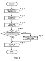
- Fig. 3 is a chart showing a flow of processes for saving and outputting the frame data executed by the image processing device 1 as described above. Although Fig. 3 shows only the flow of image processing for one frame and shows nothing about the next frame, when the moving image is actually displayed, the processes shown in Fig. 3 are repeated until a moving image ends.
- the image processing section 21 When an instruction is given to display a moving image, the image processing section 21 carries out a geometric process necessary for the image to be displayed (Step S10) . Through the geometric process, the image processing section 21 generates a display list and sends the display list to the image drawing section 22. Based on the display list sent from the image processing section 21, the image drawing section 22 generates a graphic image by rendering the polygons in the graphic memory 24 (Step S20). Accordingly, the frame data is stored in the graphic memory 24.
- the save processing section 23 saves the frame data written to the graphic memory 24 to the display memory 25 in accordance with the output state of the display memory 25 (Step S30).
- the save processing section 23 equally divides the frame data written to the graphic memory 24 to generate the partial data, the generated pieces of partial data being saved per piece of partial data.
- the save processing section 23 can save the partial data. For example, when one piece of partial data is outputted from the display memory 25, buffer areas corresponding to that piece of partial data become vacant.
- the save processing section 23 can save one piece of partial data from the graphic memory to the display memory 25. Still more, a plurality of pieces of partial data can be saved from the graphic memory to the display memory 25 after outputting the plurality of pieces of partial data from the display memory 25.
- the image transformation processing section 26 judges whether or not the transformation process must be carried out on the partial data saved to the display memory 25, and carries out the transformation process if necessary (Yes in Step S40, Step S50) .
- the partial data after the transformation process is stored again in the display memory 25.
- the partial data is outputted from the display memory 25 via the output interface 27 (Step S60).
- the instruction on whether or not the transformation process must be carried out is given to the image transformation processing section 26 in advance. For example, when an image must be enlarged or reduced corresponding to a resolution of a display unit connected to the image processing device 1, the image transformation processing section 26 is instructed that the transformation process is necessary.
- Figs. 4 to 12 are illustrations showing flows of the frame data stored in the graphic memory 24 and the display memory 25 in saving and outputting the frame data of a graphic image.
- states of the data transit from up to down in the figures.
- the graphic memory 24 is shown as if it is divided in the explanation of Fig. 4 and subsequent figures, its purpose is to facilitate the explanation and the figures do not intend to represent that the graphic memory 24 is physically and logically divided.
- the display memory 25 has four buffer areas so as to be able to store four pieces of partial data (one piece of frame data).
- a second frame data is stored in the graphic memory 24 and a quadrisected first frame data is saved and stored in the display memory 25.
- the save processing section 23 saves the pieces of partial data 2-1 through 2-3 obtained by equally dividing the second frame data from the graphic memory 24 to the display memory 25 after confirming that the partial data 1-3 has been outputted. While the pieces of partial data 2-1 through 2-3 are saved, the partial data 1-4 is outputted from the display memory 25 via the output interface 27 in succession to the output of the partial data 1-3 (Fig. 4(c)).
- the partial data 2-4 is saved from the graphic memory to the display memory (Fig. 4 (d)).
- the saving of the partial data 2-4 ends, third frame data that becomes a graphic image of the next frame starts to be rendered in the graphic memory 24.
- the display memory 25 only needs to have a storage capacity for one piece of frame data. Still more, because the saved frame data is immediately outputted, latency becomes shorter than in the case of the conventional method employing the double-buffer structure. Further, because the frame data is outputted per piece of partial data, the frame data only needs to be saved before the partial data is actually outputted even when the process exceeds the VBI interval.
- the display memory 25 has five buffer areas so as to be able to store five pieces of partial data.
- a second frame data is stored in the graphic memory 24 and a quadrisected first frame data is saved and stored in the display memory 25.
- the save processing section 23 saves pieces of partial data 2-1 through 2-4 obtained by equally dividing the second frame data from the graphic memory 24 to the display memory 25 after confirming that the partial data 1-3 has been outputted.
- the save processing section 23 causes the display memory 25 to output the partial data 1-4 (Fig. 5(c)). Because the display memory 25 can store five pieces of partial data, the display memory 25 can save all of the second frame data at once regardless of whether the partial data 1-4 is being outputted.
- the image drawing section 22 can start to render a third frame data that becomes a graphic image of the next frame regardless of the output from the display memory 25. That is, the third frame data is rendered in the graphic memory 24 regardless of whether the partial data 1-4 is being outputted.
- the saved frame data is immediately outputted, latency becomes shorter than in the case of the conventional method employing the double-buffer structure. Further, because the frame data is outputted per piece of partial data, the frame data only needs to be saved before the partial data is actually outputted even when the process exceeds the VBI interval.
- the display memory 25 is arranged so as to be capable of storing one piece of extra partial data, all pieces of partial data of the next frame may be saved from the graphic memory 24 even when all pieces of partial data saved in the display memory 25 are not outputted. Therefore, output from the display memory 25 and drawing to the graphic memory 24 may be carried out asynchronously.
- the display memory 25 has five buffer areas so as to be capable of storing five pieces of partial data.
- the display memory 25 is a memory that allows an in-place transformation process and is arranged so as to be capable of writing partial data after the transformation process into the same buffer area as the buffer area in which partial data before the transformation is to be stored.
- a second frame data is stored in the graphic memory 24 and a quadrisected first frame data is saved and transformed to be stored in the display memory 25.
- the save processing section 23 saves pieces of partial data 2-1 raw through 2-4 raw obtained by equally dividing the second frame data from the graphic memory 24 to the display memory 25 after confirming that the partial data 1-3 has been outputted.
- the save processing section 23 causes the display memory 25 to output the partial data 1-4 (Fig. 6(c)).
- the image transformation processing section 26 carries out the in-place transformation process of the pieces of partial data 2-1 raw through 2-4 raw saved in the display memory 25. Accordingly, the pieces of partial data 2-1 through 2-4 after the transformation process are stored in the display memory 25 (Fig. 6(d)).
- the display memory 25 will only need five buffer areas even when the transformation process is carried out after the saving.
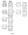
- the display memory 25 has six buffer areas so as to be able to store six pieces of partial data.
- the display memory 25 is a memory incapable of performing the in-place transformation process and partial data after the transformation process cannot be written into the same buffer area as the buffer area in which the partial data before the transformation is to be stored.
- a second frame data is stored in the graphic memory 24 and a quadrisected first frame data is saved and transformed to be stored in the display memory 25.
- the save processing section 23 saves partial data 2-1 raw obtained by equally dividing the second frame data from the graphic memory 24 to the display memory 25 after confirming that the partial data 1-3 has been outputted (Fig. 7(b)).
- the save processing section 23 saves the partial data 2-2 raw from the graphic memory 24 to the display memory 25.
- the save processing section 23 causes the display memory 25 to output the partial data 1-4 (Fig. 7(c)).
- the image transformation processing section 26 carries out the transformation process of the partial data 2-1 raw and stores the partial data 2-1 obtained as a result in a buffer area different from a buffer area in which the partial data 2-1 raw has been stored.
- the save processing section 23 saves the partial data 2-3 raw from the graphic memory 24 to the display memory 25 (Fig. 7(d)) .
- the save processing section 23 saves the partial data 2-4 raw from the graphic memory 24 to the display memory 25 (Fig. 7(e)).
- the image transformation processing section 26 carries out the transformation process of the partial data 2-4 raw (Fig. 7(f)).
- the pieces of partial data 2-2, 2-3, and 2-4 after the transformation process are also stored in the buffer areas different from buffer areas in which the pieces of partial data 2-2 raw, 2-3 raw, and 2-4 raw have been saved.
- the image drawing section 22 starts to render a third frame data that becomes a graphic image of the next frame regardless of the output from the display memory 25. That is, when saving of the second frame data ends in Fig. 7(e), drawing of the next frame is started.
- the fourth embodiment can obtain the same effect as in the third embodiment. Even when the in-place transformation by the display memory 25 cannot be carried out in this embodiment, it is possible to carry out the transformation process after the saving by increasing the storage capacity of the display memory 25 in an amount corresponding to one piece of partial data as compared with the third embodiment.
- the display memory 25 has six buffer areas so as to be able to store six pieces of partial data.
- Upper and lower pieces of partial data are used for the transformation process.
- pieces of partial data 2-1 raw and 2-3 raw are required beside partial data 2-2 raw in order to generate the partial data 2-2 by the transformation process.
- a second frame data is stored in the graphic memory 24 and a quadrisected first frame data is saved and stored in the display memory 25.
- the save processing section 23 saves partial data 2-1 raw obtained by equally dividing the second frame data from the graphic memory 24 to the display memory 25 after confirming that the partial data 1-3 has been outputted (Fig. 8(b)).
- the image transformation processing section 26 carries out the transformation process of the upper half of the partial data 2-1 (partial data 2-1 (top)) by the partial data 2-1 raw.
- the save processing section 23 saves the partial data 2-2 raw from the graphic memory 24 to the display memory 25.
- the save processing section 23 causes display memory 25 to output the partial data 1-4 (Fig. 8(c)).
- the partial data 2-1 (top) after the transformation process is stored in a buffer area different from a buffer area in which the partial data 2-1 raw has been saved.
- the image transformation processing section 26 carries out the transformation process of the lower half of the partial data 2-1 by the pieces of partial data 2-1 raw and 2-2 raw. Accordingly, the transformation process of the partial data 2-1 ends.
- the save processing section 23 saves the partial data 2-3 raw from the graphic memory 24 to the display memory 25 (Fig. 8(d)).
- the image transformation processing section 26 carries out the transformation process of the upper half of the partial data 2-2 (partial data 2-2 (top)) by the pieces of partial data 2-1 raw and 2-2 raw.
- the save processing section 23 saves the partial data 2-4 raw from the graphic memory 24 to the display memory 25 (Fig. 8(e)).
- the partial data 2-2 (top) after the transformation process is stored in the buffer area in which the partial data 2-1 raw has been saved.
- the image transformation processing section 25 carries out the transformation process of the lower half of the partial data 2-2 by the pieces of partial data 2-2 raw and 2-3 raw (Fig. 8(f)). Accordingly, the transformation process of the partial data 2-2 ends. It should be noted that saving of the second frame data has been finished by Fig. 8(e), so the image drawing section 22 may start drawing of the next frame in the graphic memory 24 in this stage.
- the image transformation processing section 26 carries out the transformation process of the upper half of the partial data 2-3 (partial data 2-3 (top)) by the pieces of partial data 2-2 raw and 2-3 raw (Fig. 8(g)) .
- the partial data 2-3 (top) after the transformation process is stored in the buffer area in which the partial data 2-2 raw has been saved.
- the image transformation processing section 26 carries out the transformation process of the lower half of the partial data 2-3 by the pieces of partial data 2-3 raw and 2-4 raw (Fig. 8(h)). Accordingly, the transformation process of the partial data 2-3 ends.
- the image transformation processing section 26 carries out the transformation process of the upper half of the partial data 2-4 (partial data 2-4 (top)) by the pieces of partial data 2-3 raw and 2-4 raw (Fig. 8 (i)).
- the partial data 2-4 (top) after the transformation process is stored in the buffer area in which the partial data 2-3 raw has been saved.
- the image transformation processing section 26 carries out the transformation process of the lower half of the partial data 2-4 by the partial data 2-4 raw (Fig. 8(j)). Accordingly, the transformation process of the partial data 2-4 ends.
- the upper and lower pieces of partial data are used in the transformation process of the partial data in the fifth embodiment. Therefore, it becomes possible to eliminate problems such as color and shape of an image at boundary parts of the partial data being discontinuous.
- the display memory 25 has seven buffer areas so as to be able to store seven pieces of partial data.
- a second frame data is stored in the graphic memory 24 and a quadrisected first frame data is saved and stored in the display memory 25.
- the save processing section 23 saves partial data 2-1 raw obtained by equally dividing the second frame data from the graphic memory 24 to the display memory 25 after confirming that the partial data 1-3 has been outputted (Fig. 9(b)).
- the save processing section 23 saves the partial data 2-2 raw from the graphic memory 24 to the display memory 25.
- the save processing section 23 causes the display memory 25 to output the partial data 1-4 (Fig. 9(c)) .
- the image transformation processing section 26 carries out the transformation process of the pieces of partial data 2-1 raw and 2-2 raw to generate the partial data 2-1.
- the generated partial data 2-1 is stored in a vacant buffer area of the display memory 25.
- the generated partial data 2-1 is stored in a buffer area subsequent to the buffer area in which the partial data 1-4 has been stored.
- the save processing section 23 saves the partial data 2-3 raw from the graphic memory 24 to the display memory 25 (Fig. 9(d)).
- the image transformation processing section 26 carries out the transformation process of the pieces of partial data 2-1 raw, 2-2 raw, and 2-3 raw to generate the partial data 2-2.
- the save processing section 23 saves the partial data 2-4 raw from the graphic memory 24 to the display memory 25 (Fig. 9(e)).
- the generated partial data 2-2 is stored in a vacant buffer area of the display memory 25, i.e., in a buffer area subsequent to the buffer area in which the partial data 2-1 has been stored.
- the image transformation processing section 26 carries out the transformation process of the pieces of partial data 2-2 raw, 2-3 raw, and 2-4 raw to generate the partial data 2-3 (Fig. 9(f)).
- the generated partial data 2-3 is stored in a vacant buffer area of the display memory 25, i.e., in a buffer area subsequent to the buffer area in which the partial data 2-2 has been stored. It should be noted that because saving of the second frame data has been finished by Fig. 9(e), the image drawing section 22 may start to render the next frame in the graphic memory 24 in this stage.
- the image transformation processing section 26 carries out the transformation process of the pieces of partial data 2-3 raw and 2-4 raw to generate the partial data 2-4 (Fig. 9(g)).
- the generated partial data 2-4 is stored in a vacant buffer area of the display memory 25, i.e., in a buffer area subsequent to the buffer area in which the partial data 2-3 has been stored.
- While the pieces of partial data 2-3 raw and 2-4 raw remaining in the display memory 25 may be deleted, they may be left and need not be deleted if they are arranged so as to be overwritten by the saving and transformation processes of the next frame.
- the partial data is not further divided into the upper and lower halves unlike the fifth embodiment. Therefore, the transformation process of all pieces of partial data may be carried out quickly while keeping the same effects as that in the fifth embodiment.
- the frame data is divided into eight parts.
- the display memory 25 has eleven buffer areas so as to be able to store eleven pieces of partial data. Because each buffer area composing the display memory 25 has the storage capacity corresponding to a data size of the partial data, when the frame data is divided into eight parts, the storage capacity is half as that in the case where it is divided into four parts.
- the seventh embodiment illustrates a case where video output signals are outputted to first and second output units whose refresh rates are different, and two video output signals are outputted from the output interface 27 in different refresh rates.
- the refresh rate of the first output unit is relatively high and the refresh rate of the second output unit is relatively low.
- a second frame data is stored in the graphic memory 24 and a first frame data divided into eight parts is saved and stored in the display memory 25.
- the save processing section 23 saves pieces of partial data 2-1 through 2-8 obtained by equally dividing the second frame data at once from the graphic memory 24 to the display memory 25 even when the output of the partial data to the second output unit has not reached the partial data 1-8 yet (Fig. 10(b)) .
- the second frame data is saved during the output of the partial data 1-3 to the second output unit.
- the display memory 25 outputs the partial data 2-1 to the first output unit after outputting the partial data 1-8. This is an output in normal sequence.
- the display memory 25 outputs the partial data 2-5 to the second output unit after outputting the partial data 1-4. Therefore, an image in which the first and second frame data are mixed is displayed on the second output unit.
- the frame data is divided into four parts.
- the display memory 25 has six buffer areas so as to be able to store six pieces of partial data.
- the image transformation processing section 26 carries out a transformation process on the frame data after the saving so that an image is reduced in the eighth embodiment.
- Frame data composed of three pieces of partial data will be generated based on four pieces of partial data in this embodiment. Accordingly, the partial data saved in the display memory 25 is transformed into a 3/4-size image by the image transformation processing section 26.
- a second frame data is stored in the graphic memory 24 and a reduced and trisected first frame data is saved and stored in the display memory 25.
- Data size of the first frame data stored in the display memory 25 is 3/4 the data size of the second frame data stored in the graphic memory 24.
- the save processing section 23 When pieces of partial data 1-1 and 1-2 are outputted sequentially from the display memory 25, the save processing section 23 saves partial data 2-1 raw obtained by equally dividing the second frame data from the graphic memory 24 to the display memory 25 after confirming that the partial data 1-2 has been outputted (Fig. 11(b)). Next, the save processing section 23 saves the partial data 2-2 raw from the graphic memory 24 to the display memory 25. At the same time, the save processing section 23 causes the display memory 25 to output the partial data 1-3 (Fig. 9(c)).
- the image transformation processing section 26 generates the partial data 2-1 from the pieces of partial data 2-1 raw and 2-2 raw and the save processing section 23 saves the partial data 2-3 raw from the graphic memory 24 (Fig. 11(d)). Then, the image transformation processing section 26 generates the partial data 2-2 from the pieces of partial data 2-2 raw and 2-3 raw and the save processing section 23 saves the partial data 2-4 raw from the graphic memory 24 (Fig. 11 (e)). Next, the image transformation processing section 26 generates the partial data 2-3 from the pieces of partial data 2-3 raw and 2-4 raw (Fig. 11(f)). Thus, the second frame data whose image is reduced to 3/4 the size is generated.
- the transformation process is carried out on the two pieces of partial data to generate one piece of partial data. Therefore, the number of divisions of the frame data after transformation becomes less than the number of divisions of the frame data before the transformation by one, so the image is reduced that much.
- the frame data is divided into four parts.
- the display memory 25 has seven buffer areas so as to be able to store seven pieces of partial data.
- the image transformation processing section 26 carries out a transformation process on the frame data after saving so that an image is enlarged.
- frame data composed of five pieces of partial data is generated based on four pieces of partial data. That is, the partial data saved to the display memory 25 is transformed into a 5/4-size image by the image transformation processing section 26.
- a second frame data is stored in the graphic memory 24 and a first frame data corresponding to five pieces of partial data is saved and transformed to be stored in the display memory 25.
- the save processing section 23 saves pieces of partial data 2-1 raw and 2-2 raw obtained by equally dividing the second frame data from the graphic memory 24 to the display memory 25.
- the save processing section 23 causes the display memory 25 to output the partial data 1-5 (Fig. 12(c)).
- the save processing section 23 saves the partial data 2-3 raw from the graphic memory 24 to the display memory 25 and the image transformation processing section 26 transforms the partial data 2-1 raw to generate the partial data 2-1 (Fig. 12 (d)) . Then, the save processing section 23 saves the partial data 2-4 raw from the graphic memory 24 to the display memory 25 and the image transformation processing section 26 transforms the pieces of partial data 2-1 raw and 2-2 raw to generate the partial data 2-2 (Fig. 12(e)).
- the image transformation processing section 26 transforms the pieces of partial data 2-2 raw and 2-3 raw to generate the partial data 2-3 (Fig. 12(f)). Then, the image transformation processing section 26 transforms the pieces of partial data 2-3 raw and 2-4 raw to generate the partial data 2-4 (Fig. 12(g)). Next, the image transformation processing section 26 transforms the partial data 2-4 raw to generate partial data 2-5 (Fig. 12(h)).
- the image transformation processing section 26 carries out the transformation process on the pieces of partial data 2-1 raw and 2-4 raw to generate one piece of partial data each, and carries out the transformation process on the two pieces of partial data to generate one piece of partial data. Therefore, the number of divisions of the frame data after the transformation increases by one as compared with the number of divisions of the frame data before the transformation, so the image is enlarged that much. It should be noted that drawing of the third frame data may be started any time as long as the saving of the frame data from the graphic memory 24 to the display memory 25 has ended.
- the tenth embodiment is an example of saving and outputting processes executed by an image processing device 2 whose configuration is different from the image processing device 1 used in the first to ninth embodiments described above.
- data size of the partial data after the transformation process is increased as compared with data size of partial data before the transformation process. Therefore, when the partial data after the transformation process is intended to be stored in each buffer area of the display memory 25, each of the buffer areas causes an overflow. Then, an output FIFO (First-In First-Out) for storing the partial data after the transformation process stores the partial data after the transformation process in this embodiment.
- FIFO First-In First-Out
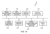
- Fig. 13 is a functional block diagram of the image processing device 2 for realizing such the process.
- the same components as those in Fig. 2 are denoted by the same reference numerals.
- a part in which an output FIFO 28 is added is different.
- the output FIFO 28 may be configured by the main memory 11 or another dedicated memory may be prepared.
- the output FIFO 28 is provided with three buffer areas sufficient for storing one piece of partial data after transformation process.
- a storage capacity of a buffer area provided in the output FIFO 28 is larger than a storage capacity of the buffer area provided in the display memory 25.
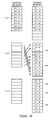
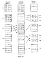
- Figs. 14(a) to 14(e) explain processes carried out by the image processing device 2 shown in Fig. 13.
- the frame data is quadrisected in Figs. 14(a) to 14(e).
- the display memory 25 is provided with five buffer areas so as to be able to store five pieces of partial data.
- the frame data stored in the graphic memory 24 is transformed by the image transformation processing section 26 and is then written into the output FIFO 28 after being saved in the display memory 25.
- the output interface 27 outputs the transformed frame data from the output FIFO 28.
- the second frame data is stored in the graphic memory 24 and the quadrisected first frame data is saved and stored in the display memory 25.
- Pieces of partial data 1-1 raw through 1-3 raw are sequentially transformed by the image transformation processing section 26 to be sent to the output FIFO 28 from the display memory 25, and are outputted in the stated order of the partial data 1-1, 1-2, and 1-3 (Fig. 14(b)).
- partial data 1-4 raw is transformed by the image transformation processing section 26, is sent to the output FIFO 28, and is outputted.
- the save processing section 23 saves pieces of partial data 2-1 raw through 2-4 raw obtained by equally dividing the second frame data from the graphic memory 24 to the display memory 25 (Fig. 14(c)).
- the saved pieces of partial data 2-1 raw through 2-3 raw are sequentially transformed by the image transformation processing section 26, are sent to the output FIFO 28 from the display memory 25, and are outputted in the stated order of the partial data 2-1, 2-2, and 2-3 (Fig. 14(d)).
- the partial data 2-4 raw is transformed by the image transformation processing section 26, is sent to the output FIFO 28, and is outputted (Fig. 14(e)).
- the third frame data is written to the graphic memory 24 in and after the stage of Fig. 14(d) at which all pieces of the second frame data are saved from the graphic memory 24.
- the display memory 25 may be provided outside the image processing device 1.
- the display memory 25 may be provided within the display unit connected with the image processing device 1 so as to directly transmit frame data from the graphic memory 24 without the intermediation of the CRTC 20 and the like. In this case, the frame data is transformed into a video output signal within the display unit.
- the display memory 25 may be provided within a separate unit via a network.
- Fig. 15 is an exemplary illustration of an image processing device utilizing the network.
- the display memory 25, the image transformation processing section 26, and the output interface 27 are provided on the network L by being separated from the image processing device 1 of Fig. 2.
- the frame data drawn into the graphic memory 24 is saved to the display memory 25 via the network L. Further, the frame data is sent as a video output signal from the display memory 25 to the display unit 3 via the network.
- the display unit 3 may be provided with the display memory 25, the image transformation processing section 26, and the output interface 27.
Landscapes
- Engineering & Computer Science (AREA)
- Physics & Mathematics (AREA)
- Computer Hardware Design (AREA)
- General Physics & Mathematics (AREA)
- Theoretical Computer Science (AREA)
- Multimedia (AREA)
- Controls And Circuits For Display Device (AREA)
Abstract
Description
- The present invention relates to an image processing device whose latency is improved without increasing a storage capacity of a memory used for image processing as much as possible, and to an image processing method executed by the image processing device, an image processing system, and a computer program.
- In a field of image processing, there is a case where an graphic image drawn in a frame memory is temporarily saved to a display memory and is outputted to a display unit or the like from the display memory by transforming the graphic image into a video output signal conforming to a standard such as an NTSC system. Saving the graphic image from the frame memory allows an image of a next frame to be drawn in the frame memory even when the video output signal is being outputted.
- Saving of the graphic image from the frame memory to the display memory is carried out after a display of a previous frame is finished. Saving from the frame memory to the display memory is carried out during VBI (Vertical Blank Interval). There is also a case where the transformation process is carried out on the graphic image that has been saved to the display memory. In this case, the conversion process must also be carried out during the VBI as well as the saving. Because saving and transformation processes that can be carried out during the VBI are limited, a size and definition of a displayable image may be determined by such the limitation. Still more, drawing to the frame memory can only be carried out after finishing the save. Therefore, drawing to the frame memory cannot be carried out asynchronously with the output.
- As one measure for solving these problems, the display memory has a double-buffer structure. By using the display memory with the double-buffer structure, it becomes possible to carry out the processes such as saving of a graphic to another display memory and transformation thereof while displaying an image from one display memory on a display unit, so it becomes unnecessary to finish the saving and transformation processes during the VBI. Still more, drawing and output may be carried out asynchronously because drawing to the frame memory can be carried out immediately after finishing the saving.
- However, it is not economical to provide the display memory with the double-buffer structure because storage capacity of the display memory will need at least twice the capacity as the frame buffer. Still more, there arises a problem in that latency increases.
- Accordingly, an object of the present invention is to solve the above-mentioned problems and to provide an image processing technique which shortens latency more than the conventional method employing the double-buffer structure, enables the saving and transformation processes to be carried out outside the VBI interval, and enables drawing and output to be carried out asynchronously while suppressing an increase amount of the display memory to the minimum.
- An image processing device of the present invention made to solve the above-mentioned problems includes: image processing means for carrying out predetermined image processing per frame of a moving image, and storing frame data representing an image corresponding to a result of the image processing to a predetermined graphic memory; save processing means for saving the frame data stored in the graphic memory to a predetermined display memory in a unit of partial data of the frame data equally divided; and an output interface for transforming the frame data saved in the display memory into a video output signal in the unit of partial data and outputting the video output signal to the outside.
- The frame data is saved in the display memory as partial data divided into a plurality of parts. The frame data is outputted from the display memory not at once but in a unit of partial data. The use of the partial data enables the data to be outputted before the entire frame data is saved, so the latency becomes shorter than in the conventional case of employing the double-buffer structure for the display memory.
- The partial data needs to be at least saved before reaching the timing when the partial data is outputted from the display memory. For example, at least partial data outputted right after a VBI interval needs to be saved, so the process for saving the frame data may be carried out even outside the VBI interval. Still more, when a transformation process is carried out on the saved partial data, the saving and transformation processes of other partial data need to at least end before reaching the actual output timing even when exceeding the VBI interval if the saving and transformation processes of the partial data outputted right after the VBI interval have been carried out. Still more, the use of the display memory allows the drawing and output to be carried out asynchronously because drawing to the graphic memory becomes possible if the frame data is saved from the graphic memory to the display memory.
- When the display memory has a plurality of buffer areas, for example, the save processing means is arranged so as to store pieces of partial data, which are obtained by equally dividing the frame data stored in the graphic memory into a number equal to or less than the number of buffer areas of the display memory and into a data size that can be stored in each of the buffer areas, to the buffer areas whose number corresponds to the number of the pieces of partial data.
- The buffer area may be a storage area logically formed in the memory unit or a storage area formed physically by a plurality of memory units. The buffer area may also be formed logically and physically by the plurality of memory units.
- For example, the display memory is provided with the buffer area in a number capable of storing frame data of one frame or more and less than two frames. Such configuration allows the storage capacity of the memory used for the display memory to be reduced more than the case of employing the double-buffer structure for the display memory.
- In addition, the save processing means is arranged, for example, to be able to confirm states of saving of the partial data from the graphic memory to the display memory and states of output of the partial data stored in the display memory, and to save the partial data from the graphic memory to the display memory in accordance with the output state of the partial data from the display memory.
- Such the image processing device can be arranged so as to carry out the following saving and transformation processes.
- For example, in a case where the display memory is provided with "n", which is an integer of "2" or more, buffer areas, and the pieces of partial data of the frame data equally divided into "n" parts by the save processing means are respectively stored in each of the buffer areas, when "m", which is an integer represented by "1 m (n - 1) ", pieces of partial data are outputted from the display memory, the save processing means is arranged such that the "m" pieces of partial data among frame data of a next frame stored in the graphic memory equally divided into "n" parts are saved to the buffer areas of the display memory from which the pieces of partial data have been outputted, and when remaining pieces of partial data of the same frame data as the partial data previously outputted from the display buffer are outputted in succession, the remaining pieces of partial data from the graphic memory are saved to the buffer areas of the display memory.
- In addition, when the display memory is provided with "(n + 1) ", where "n" is an integer of "2" or more, buffer areas, and the pieces of partial data of the frame data equally divided into "n" parts by the save processing means are stored in the "n" buffer areas, the save processing means is arranged so as to save the frame data stored in the graphic memory to the display memory by equally dividing the frame data into "n" pieces of partial data when the partial data of " (n - 1)" pieces are outputted from the display memory.
- In these cases, an image processing device may further include image transformation processing means for carrying out a predetermined transformation process on the pieces of partial data saved in the buffer areas of the display memory, and for storing results of the transformation process in the buffer areas in which the pieces of partial data have been stored.
- Further, for example, in a case where an image processing device is made to further include image transformation processing means for carrying out a predetermined transformation process on the partial data saved in the display memory, the display memory is provided with " (n + 2) ", where "n" is an integer of "2" or more, buffer areas, and pieces of partial data of the frame data equally divided into "n" parts by the save processing means are stored in the "n" buffer areas, when "m", where "m" is an integer represented by "1 m (n - 1) " , pieces of partial data is outputted from the display memory, the save processing means may be arranged such that the "m" pieces of partial data among next frame data equally divided into "n" parts from the graphic memory are saved to the display memory, and when remaining pieces of partial data of the same frame data as the partial data previously outputted from the display buffer are outputted in succession, the remaining pieces of partial data from the graphic memory are saved to the buffer areas of the display memory. Further, the image transformation processing means may be arranged so as to carry out the predetermined transformation process on the pieces of partial data saved in the buffer areas, and to store results of the transformation process in the buffer areas except the buffer areas in which the partial data has been saved and in which the pieces of partial data divided from the same frame data as the partial data have been saved.
- Further, for example, in a case where an image processing device further includes image transformation processing means for carrying out a predetermined transformation process on the partial data saved in the display memory, the display memory is provided with "(n + 3)", where "n" is an integer of "2" or more, buffer areas, and pieces of partial data of the frame data equally divided into "n" parts by the save processing means are stored in the "n" buffer areas, when "m", which is an integer represented by "1 m (n - 1)", pieces of partial data are outputted from the display memory, the save processing means may be arranged such that the partial data from the graphic memory are saved to the display memory, and when remaining pieces of partial data of the same frame data as the partial data previously outputted from the display buffer are outputted in succession, the remaining pieces of partial data from the graphic memory are saved to the buffer areas of the display memory. Further, the image transformation processing means may be arranged so as to carry out the predetermined transformation process on one or more pieces of partial data saved in the buffer areas, and to store results of the transformation process in the buffer areas except the buffer areas in which the partial data used for the transformation process has been saved and in which the pieces of partial data divided from the same frame data as the partial data have been saved.
- Further, for example, in a case where the output interface is arranged so as to output "k" ("k" is an integer of "2" or more) video output signals at different refresh rates, the display memory is provided with "(n + 2k -1)", where "n" is an integer that satisfies "n > 2k - 1", buffer areas, and pieces of partial data of the frame data equally divided into "n" parts by the save processing means are stored in the "n" buffer areas, when outputs of " (n - 1) " pieces of partial data have ended at a fastest refresh rate, the save processing means may be arranged such that partial data of frame data of a next frame from the graphic memory is saved to the buffer areas except the buffer areas storing the partial data being outputted at another refresh rate and pieces of partial data to be outputted next at respective refresh rates.
- According to the present invention, there is provided an image processing device including: image processing means for carrying out predetermined image processing per frame of a moving image and storing frame data representing an image corresponding to results of the image processing to a predetermined graphic memory; a display memory provided with "(n + 1)", where "n" is an integer of "2" or more, display buffer areas, for storing the frame data in each of the buffer areas by dividing the frame data; an output memory provided with " (n - 1) " output buffer areas whose storage capacity is larger than that of the display buffer area; save processing means for saving partial data of the frame data stored in the graphic memory and equally divided into "n" parts to each one of the "n" display buffer areas one by one; image transformation processing means for carrying out a predetermined transformation process on the partial data saved in the display memory to store a result of the processing indicating data whose data size is larger than that of the partial data in the output buffer; and an output interface for outputting the result of the processing stored in the output memory to the outside by transforming the result into a video output signal, in which, when "(n - 1)" pieces of partial data are transformed by the image transformation processing means and outputted from the display memory, the save processing means saves "n" pieces of partial data from the graphic memory to the display memory.
- According to the present invention, there is provided an image processing system including: image processing means for carrying out predetermined image processing per frame of a moving image, and for storing frame data representing an image corresponding to a result of the image processing to a predetermined graphic memory; a display memory provided with a plurality of buffer areas, for storing the frame data to each of the buffer areas by dividing the frame data; save processing means for saving the frame data stored in the graphic memory to the display memory; and an output interface for transforming the frame data saved in the display memory into video output signals and outputting the signals to the outside, in which: the save processing means is arranged so as to store the frame data stored in the graphic memory by equally dividing the frame data into a plurality of pieces of partial data in a number equal to or less than the number of buffer areas of the display memory and into a data size that can be stored in each of the buffer areas, to the buffer areas whose number corresponds to the number of the pieces of partial data; and the graphic memory and the display memory are provided in different units connected via a network.
- According to the present invention, there is provided an image processing method executed in a device having save processing means for saving frame data representing an image corresponding to a result of predetermined image processing carried out per frame of a moving image from a graphic memory in which the frame data is stored to a predetermined display memory, and which causes a predetermined display unit to display the frame data saved in the display memory by transforming the frame data into a video output signal, the method comprising the steps of saving, by the save processing means, partial data obtained by equally dividing the frame data from the graphic memory to the display memory in a unit of partial data, and outputting the frame data saved to the display memory in the unit of partial data.
- With such the image processing method, when the display memory has a plurality of buffer areas, the method further comprises generating, by the save processing means, pieces of partial data by equally dividing the frame data stored in the graphic memory in a number equal to or less than the number of buffer areas of the display memory and into a data size that can be stored in each of the buffer areas, and saving, by the save processing means, the pieces of partial data to the buffer areas whose number corresponds to the number of pieces of partial data.
- A computer program according to the present invention is a computer program for a computer that saves frame data representing an image corresponding to a result of predetermined image processing carried out per frame of a moving image from a graphic memory in which the frame data is stored to a predetermined display memory, and which causes a predetermined display unit to display the frame data saved in the display memory by transforming the frame data into a video output signal, the computer program causing the computer to execute a process of saving the partial data obtained by equally dividing the frame data from the graphic memory to the display memory in a unit of partial data, and outputting the frame data saved in the display memory in the unit of partial data.
- A semiconductor device according to the present invention is a semiconductor device that can be mounted in a device for carrying out predetermined image processing per frame of a moving image and displaying an image corresponding to a result of the image processing on a predetermined display unit, including: a graphic memory for storing frame data representing an image corresponding to a result of the image processing; a display memory for storing the frame data equally divided; save processing means for saving the frame data stored in the graphic memory to the display memory per piece of partial data obtained by equally dividing the frame data; and an output interface for transforming the frame data saved in the display memory into a video output signal per piece of partial data and outputting the signal to the display unit.
-
- Fig. 1 is a diagram of a whole configuration of an image processing device according to an embodiment mode of the present invention.
- Fig. 2 is a functional block diagram of functions formed in the image processing device of the embodiment mode.
- Fig. 3 is a flowchart showing processing of the image processing device of the embodiment mode.
- Figs. 4 is exemplary illustrations of a saving process of the present invention.
- Figs. 5 is exemplary illustrations of the saving process of the present invention.
- Figs. 6 is exemplary illustrations of the saving process of the present invention.
- Figs. 7 is exemplary illustrations of the saving process of the present invention.
- Figs. 8 is exemplary illustrations of the saving process of the present invention.
- Figs. 9 is exemplary illustrations of the saving process of the present invention.
- Figs. 10 is exemplary illustrations of the saving process of the present invention.
- Figs. 11 is exemplary illustrations of the saving process of the present invention.
- Figs. 12 is exemplary illustrations of the saving process of the present invention.
- Fig. 13 is another functional block diagram of functions formed in the image processing device of the embodiment mode.
- Figs. 14 is exemplary illustrations of the saving process of the present invention.
- Fig. 15 is an exemplary illustration of the image processing device using a network.
- Hereinafter, an embodiment mode of the present invention will be explained in detail.
- Fig. 1 is a diagram showing a hardware configuration of an image processing device of the present invention.
- The
image processing device 1 displays an image on a display unit (not shown) and outputs sounds from a speaker or the like by reading and processing programs and data stored in amedia 141 such as a CD-ROM or a DVD-ROM. Such theimage processing device 1 may be realized by, for example, a general-purpose computer, a video game machine, an entertainment device, and the like having an image processing function. - The
image processing device 1 is composed of a CPU (Central Processing Unit) 10, a main memory 11 composed of a RAM, a DMAC (Direct Memory Access Controller) 12, an MPEG (Moving Picture Experts Group) decoder (MDEC) 13, amedia drive 14 for mounting amedia 141, ainput section 15, aROM 16 in which programs such as BIOS are recorded, a sound processing unit (referred to as "SPU" hereinafter) 17 for reading sound data accumulated in asound memory 171 to output as audio output signal, a graphic processing unit (referred to as "GPU" hereinafter) 18 having aframe memory 19, theframe memory 19 in which images are drawn by theGPU 18, and a CRTC (CRT Controller) 20 for generating a video output signal. These are connected with each other through buses B. - The video output signal is generated in conformity with standards such as NTSC (National Television Standards Committee) and PAL (Phase Alternation by Line) and is outputted from the
CRTC 20 to a display unit. - The
CPU 10 is a semiconductor device that reads a starting program out of theROM 16 in starting theimage processing device 1, and executes the starting program to operate an operating system. TheCPU 10 also controls the media drive 14 so as to read an application program out of themedia 141 mounted to the media drive 14 and to store the read application program in the main memory 11. TheCPU 10 further has a function of reading data necessary for generating an image such as 3-D graphic data (such as coordinate values of apexes of a polygon), texture data, and the like composed of a plurality of basic graphics (polygons) out of themedia 141, and storing the data in theauxiliary storage unit 19. The 3-D graphic data represents an object image in a 3-D image. - The
CPU 10 also has a function of carrying out a geometric process such as coordinate transformation process and perspective transformation process on the 3-D graphic data to generate a display list containing contents of polygon definition information (specification of position, color, texture coordinates, fog color, and the like of the apex and center of gravity of the polygon to be used) obtained by the geometric process. - The
GPU 18 is a semiconductor device that has a function of generating a graphic image by rendering the polygons in theframe memory 19 by carrying out a rendering process by using the display list. TheGPU 18 carries out the rendering process by the 3-D graphic data and texture data specified in the display list. - Although the
image processing device 1 is provided with theCPU 10 and theGPU 18 as separate pieces of hardware, theimage processing device 1 may use a processor unit having these functions at the same time. - The
SPU 17 is a semiconductor device for generating an audio output signal by synthesizing sound data read out of thesound memory 171. TheDMAC 12 is a semiconductor device for carrying out DMA transfer control on each circuit connected to the bus B, and theMDEC 13 is a semiconductor device that operates in parallel with theCPU 10 and has a function of elongating data compressed by the method such as an MPEG (Moving Picture Experts Group) system or a JPEG (Joint Photographic Experts Group) system. - The
input section 15 has a connection terminal 15a to which an input signal from anoperating unit 151 is inputted. Theoperating unit 151 is provided with a plurality of operating buttons and an operator can move and deform an object image displayed on the display unit by variously operating these operating buttons. A keyboard, a mouse, a controller of a video game machine, and the like may be used as theoperating unit 151, for example. - In the
image processing device 1 configured as described above, a graphic image drawn in theframe memory 19 is equally divided and saved in the main memory 11. Data of the graphic image drawn in theframe memory 19 is referred to as frame data in this specification. The frame data of a first frame will be expressed as first frame data, the frame data of a second frame will be expressed as second frame data, and the frame data of an n-th frame will be expressed as n-th frame data. The data generated by being equally divided will be referred to as partial data in this specification. In the case of quadrisection, for example, the partial data of the first frame data will be expressed as partial data 1-1, 1-2, 1-3, and 1-4. The partial data of the n-th frame data will be expressed as partial data n-1, n-2, n-3, and n-4, respectively. - Saving is carried out per piece of partial data. The
CRTC 20 transforms the saved partial data into a video output signal and outputs the signal per piece of partial data. Therefore, a functional block as shown in Fig. 2 is formed by theCPU 10, theGPU 18, and the like in theimage processing device 1. TheCPU 10 and theGPU 18 form each functional block by executing programs recorded in theROM 16, themedia 141, and the like. - An
image processing section 21, animage drawing section 22, a save processingsection 23, agraphic memory 24, adisplay memory 25, an imagetransformation processing section 26, and anoutput interface 27 are formed in theimage processing device 1. Theimage processing section 21 is composed of theCPU 10 and theimage drawing section 22 is composed of theGPU 18. The save processingsection 23 is composed of any one of theCPU 10, theGPU 18, and theCRTC 20, or in combination thereof. Thegraphic memory 24 is composed of theframe memory 19 and thedisplay memory 25 is composed of the main memory 11. Theoutput interface 27 is composed of theCRTC 20. The imagetransformation processing section 26 is composed either of theCPU 10 or theGPU 18, or in combination thereof. - It should be noted that although the
image processing section 21 and theimage drawing section 22 are shown as different functional blocks in this embodiment mode, it is possible to arrange a functional block having these functions at the same time. - The
image processing section 21 generates the display list by carrying out the geometric process per frame of a moving image, and sends the generated display list to theimage drawing section 22. When theimage processing section 21 outputs the display list of an image of one frame to theimage drawing section 22, theimage processing section 21 is put into the state where theimage processing section 21 can execute the geometric process for an image of a next frame. The geometric process of the image of the next frame is executed, for example, so that a display list of the frame is generated before the drawing of an image to thegraphic memory 24 carried out by theimage drawing section 22 ends. - The
image drawing section 22 draws the polygons to thegraphic memory 24 based on the display list sent from theimage processing section 21, and generates a graphic image in that frame. Accordingly, the frame data is stored in thegraphic memory 24. When theimage drawing section 22 receives notification from the save processingsection 23 that saving of the graphic image from thegraphic memory 24 to thedisplay memory 25 is finished, theimage drawing section 22 is put into the state where theimage drawing section 22 can render an image of the next frame. - The
graphic memory 24 has a storage capacity sufficient for storing at least frame data for one frame. The graphic image (frame data) is saved in a unit of partial data when it is saved from thegraphic memory 24 to thedisplay memory 25. However, while the graphic image is stored in thegraphic memory 24, it is stored without being divided. - The
display memory 25 is provided with buffer areas each having a storage capacity sufficient for storing only one piece of partial data, in a number sufficient for storing frame data of one frame or more and less than two frames. When the image is divided into four, thedisplay memory 25 is provided with four to seven buffer areas. When thedisplay memory 25 outputs the partial data as video output signals, thedisplay memory 25 outputs the signals per piece of partial data. Although the respective buffer areas may be configured physically by separate memories, the buffer areas are logically divided and formed within the main memory 11 in this embodiment mode. - Although the embodiment mode in which the
display memory 25 is provided with the respective buffer areas will be explained in this embodiment mode for ease of comprehension of the present invention, it is not necessary for thedisplay memory 25 to be provided with the buffer areas as long as the frame data is stored in the units of partial data. That is, thedisplay memory 25 needs to be at least provided with a storage capacity sufficient for storing partial data of frame data of one frame or more and less than two frames. - The save processing
section 23 generates the partial data by equally dividing the frame data stored in thegraphic memory 24, and saves the frame data to thedisplay memory 25 in the units of partial data. The save processingsection 23 is also arranged so as to output the frame data from thedisplay memory 25 in the unit of partial data. Therefore, the save processingsection 23 is arranged so as to be able to confirm states of rendering of graphic image to thegraphic memory 24, states of saving of the frame data from thegraphic memory 24 to thedisplay memory 25, and states of output from thedisplay memory 25. It should be noted that although saving and output of the partial data is basically carried out one piece each time, necessary number of partial data may be saved and outputted at once when a plurality of pieces of partial data are saved and outputted continuously. - The save processing
section 23 confirms the states of saving of the frame data from thegraphic memory 24 to thedisplay memory 25 and the states of output from thedisplay memory 25 by being informed of from which buffer area within thedisplay memory 25 the partial data is outputted. That is, the save processingsection 23 confirms the saving and output states of the frame data by managing the input and output of data to/from thedisplay memory 25. - The image
transformation processing section 26 carries out a transformation process on the graphic image saved to thedisplay memory 25. The transformation process includes enlargement and reduction of a graphic image, for example. The imagetransformation processing section 26 can execute the process for enlarging or reducing the graphic image with respect to one piece of partial data. - Fig. 3 is a chart showing a flow of processes for saving and outputting the frame data executed by the
image processing device 1 as described above. Although Fig. 3 shows only the flow of image processing for one frame and shows nothing about the next frame, when the moving image is actually displayed, the processes shown in Fig. 3 are repeated until a moving image ends. - When an instruction is given to display a moving image, the
image processing section 21 carries out a geometric process necessary for the image to be displayed (Step S10) . Through the geometric process, theimage processing section 21 generates a display list and sends the display list to theimage drawing section 22. Based on the display list sent from theimage processing section 21, theimage drawing section 22 generates a graphic image by rendering the polygons in the graphic memory 24 (Step S20). Accordingly, the frame data is stored in thegraphic memory 24. - When the process for drawing to the
graphic memory 24 ends, the save processingsection 23 saves the frame data written to thegraphic memory 24 to thedisplay memory 25 in accordance with the output state of the display memory 25 (Step S30). The save processingsection 23 equally divides the frame data written to thegraphic memory 24 to generate the partial data, the generated pieces of partial data being saved per piece of partial data. When thedisplay memory 25 has at least one buffer area into which no partial data is written, the save processingsection 23 can save the partial data. For example, when one piece of partial data is outputted from thedisplay memory 25, buffer areas corresponding to that piece of partial data become vacant. Thus, the save processingsection 23 can save one piece of partial data from the graphic memory to thedisplay memory 25. Still more, a plurality of pieces of partial data can be saved from the graphic memory to thedisplay memory 25 after outputting the plurality of pieces of partial data from thedisplay memory 25. - The image
transformation processing section 26 judges whether or not the transformation process must be carried out on the partial data saved to thedisplay memory 25, and carries out the transformation process if necessary (Yes in Step S40, Step S50) . The partial data after the transformation process is stored again in thedisplay memory 25. When the transformation process ends or when the transformation process is not necessary (No in Step S40), the partial data is outputted from thedisplay memory 25 via the output interface 27 (Step S60). The instruction on whether or not the transformation process must be carried out is given to the imagetransformation processing section 26 in advance. For example, when an image must be enlarged or reduced corresponding to a resolution of a display unit connected to theimage processing device 1, the imagetransformation processing section 26 is instructed that the transformation process is necessary. - Concrete operations of the processes for saving and outputting the frame data executed by the
image processing device 1 will be explained below with reference to Figs. 4 to 12. Figs. 4 to 12 are illustrations showing flows of the frame data stored in thegraphic memory 24 and thedisplay memory 25 in saving and outputting the frame data of a graphic image. In Figs. 4 to 12, states of the data transit from up to down in the figures. It should be noted that although thegraphic memory 24 is shown as if it is divided in the explanation of Fig. 4 and subsequent figures, its purpose is to facilitate the explanation and the figures do not intend to represent that thegraphic memory 24 is physically and logically divided. - In Figs. 4 (a) to 4 (d), the
display memory 25 has four buffer areas so as to be able to store four pieces of partial data (one piece of frame data). - In Fig. 4(a), a second frame data is stored in the
graphic memory 24 and a quadrisected first frame data is saved and stored in thedisplay memory 25. When pieces of partial data 1-1 through 1-3 are outputted sequentially from thedisplay memory 25 via the output interface 27 (Fig. 4(b)), the save processingsection 23 saves the pieces of partial data 2-1 through 2-3 obtained by equally dividing the second frame data from thegraphic memory 24 to thedisplay memory 25 after confirming that the partial data 1-3 has been outputted. While the pieces of partial data 2-1 through 2-3 are saved, the partial data 1-4 is outputted from thedisplay memory 25 via theoutput interface 27 in succession to the output of the partial data 1-3 (Fig. 4(c)). When the partial data 1-4 has been outputted, the partial data 2-4 is saved from the graphic memory to the display memory (Fig. 4 (d)). When the saving of the partial data 2-4 ends, third frame data that becomes a graphic image of the next frame starts to be rendered in thegraphic memory 24. - This is an embodiment of the simplest saving and outputting processes. The
display memory 25 only needs to have a storage capacity for one piece of frame data. Still more, because the saved frame data is immediately outputted, latency becomes shorter than in the case of the conventional method employing the double-buffer structure. Further, because the frame data is outputted per piece of partial data, the frame data only needs to be saved before the partial data is actually outputted even when the process exceeds the VBI interval. - In Figs. 5 (a) to 5(c), the
display memory 25 has five buffer areas so as to be able to store five pieces of partial data. - In Fig. 5(a), a second frame data is stored in the
graphic memory 24 and a quadrisected first frame data is saved and stored in thedisplay memory 25. When pieces of partial data 1-1 through 1-3 are outputted sequentially from thedisplay memory 25 via the output interface 27 (Fig. 5(b)), the save processingsection 23 saves pieces of partial data 2-1 through 2-4 obtained by equally dividing the second frame data from thegraphic memory 24 to thedisplay memory 25 after confirming that the partial data 1-3 has been outputted. At the same time, the save processingsection 23 causes thedisplay memory 25 to output the partial data 1-4 (Fig. 5(c)). Because thedisplay memory 25 can store five pieces of partial data, thedisplay memory 25 can save all of the second frame data at once regardless of whether the partial data 1-4 is being outputted. - After saving the pieces of partial data 2-1 through 2-4, the
image drawing section 22 can start to render a third frame data that becomes a graphic image of the next frame regardless of the output from thedisplay memory 25. That is, the third frame data is rendered in thegraphic memory 24 regardless of whether the partial data 1-4 is being outputted. - Because the saved frame data is immediately outputted, latency becomes shorter than in the case of the conventional method employing the double-buffer structure. Further, because the frame data is outputted per piece of partial data, the frame data only needs to be saved before the partial data is actually outputted even when the process exceeds the VBI interval.
- Because the
display memory 25 is arranged so as to be capable of storing one piece of extra partial data, all pieces of partial data of the next frame may be saved from thegraphic memory 24 even when all pieces of partial data saved in thedisplay memory 25 are not outputted. Therefore, output from thedisplay memory 25 and drawing to thegraphic memory 24 may be carried out asynchronously. - In Figs. 6 (a) to 6(d), the
display memory 25 has five buffer areas so as to be capable of storing five pieces of partial data. Thedisplay memory 25 is a memory that allows an in-place transformation process and is arranged so as to be capable of writing partial data after the transformation process into the same buffer area as the buffer area in which partial data before the transformation is to be stored. - In Fig. 6(a), a second frame data is stored in the
graphic memory 24 and a quadrisected first frame data is saved and transformed to be stored in thedisplay memory 25. When pieces of partial data 1-1 through 1-3 are outputted sequentially from thedisplay memory 25 via the output interface 27 (Fig. 6(b)), the save processingsection 23 saves pieces of partial data 2-1 raw through 2-4 raw obtained by equally dividing the second frame data from thegraphic memory 24 to thedisplay memory 25 after confirming that the partial data 1-3 has been outputted. At the same time, the save processingsection 23 causes thedisplay memory 25 to output the partial data 1-4 (Fig. 6(c)). - Next, the image
transformation processing section 26 carries out the in-place transformation process of the pieces of partial data 2-1 raw through 2-4 raw saved in thedisplay memory 25. Accordingly, the pieces of partial data 2-1 through 2-4 after the transformation process are stored in the display memory 25 (Fig. 6(d)). - Because the in-place transformation of the
display memory 25 can be carried out while maintaining the same effect as that of the second embodiment, thedisplay memory 25 will only need five buffer areas even when the transformation process is carried out after the saving. - In Figs. 7(a) to 7(f), the
display memory 25 has six buffer areas so as to be able to store six pieces of partial data. Thedisplay memory 25 is a memory incapable of performing the in-place transformation process and partial data after the transformation process cannot be written into the same buffer area as the buffer area in which the partial data before the transformation is to be stored. - In Fig. 7(a), a second frame data is stored in the
graphic memory 24 and a quadrisected first frame data is saved and transformed to be stored in thedisplay memory 25. When pieces of partial data 1-1 through 1-3 are outputted sequentially from thedisplay memory 25, the save processingsection 23 saves partial data 2-1 raw obtained by equally dividing the second frame data from thegraphic memory 24 to thedisplay memory 25 after confirming that the partial data 1-3 has been outputted (Fig. 7(b)). Next, in parallel with the transformation process of the partial data 2-1 raw carried out by the imagetransformation processing section 26, the save processingsection 23 saves the partial data 2-2 raw from thegraphic memory 24 to thedisplay memory 25. At the same time, the save processingsection 23 causes thedisplay memory 25 to output the partial data 1-4 (Fig. 7(c)). The imagetransformation processing section 26 carries out the transformation process of the partial data 2-1 raw and stores the partial data 2-1 obtained as a result in a buffer area different from a buffer area in which the partial data 2-1 raw has been stored. - Next, in parallel with the transformation process of the partial data 2-2 raw carried out by the image
transformation processing section 26, the save processingsection 23 saves the partial data 2-3 raw from thegraphic memory 24 to the display memory 25 (Fig. 7(d)) . Then, in parallel with the transformation process of the partial data 2-3 raw carried out by the imagetransformation processing section 26, the save processingsection 23 saves the partial data 2-4 raw from thegraphic memory 24 to the display memory 25 (Fig. 7(e)). Next, the imagetransformation processing section 26 carries out the transformation process of the partial data 2-4 raw (Fig. 7(f)). The pieces of partial data 2-2, 2-3, and 2-4 after the transformation process are also stored in the buffer areas different from buffer areas in which the pieces of partial data 2-2 raw, 2-3 raw, and 2-4 raw have been saved. When saving of the partial data 2-4 raw ends, theimage drawing section 22 starts to render a third frame data that becomes a graphic image of the next frame regardless of the output from thedisplay memory 25. That is, when saving of the second frame data ends in Fig. 7(e), drawing of the next frame is started. - The fourth embodiment can obtain the same effect as in the third embodiment. Even when the in-place transformation by the
display memory 25 cannot be carried out in this embodiment, it is possible to carry out the transformation process after the saving by increasing the storage capacity of thedisplay memory 25 in an amount corresponding to one piece of partial data as compared with the third embodiment. - In Figs. 8 (a) to 8(j), the
display memory 25 has six buffer areas so as to be able to store six pieces of partial data. Upper and lower pieces of partial data are used for the transformation process. For example, pieces of partial data 2-1 raw and 2-3 raw are required beside partial data 2-2 raw in order to generate the partial data 2-2 by the transformation process. - In Fig. 8(a), a second frame data is stored in the
graphic memory 24 and a quadrisected first frame data is saved and stored in thedisplay memory 25. When pieces of partial data 1-1 through 1-3 are outputted sequentially from thedisplay memory 25, the save processingsection 23 saves partial data 2-1 raw obtained by equally dividing the second frame data from thegraphic memory 24 to thedisplay memory 25 after confirming that the partial data 1-3 has been outputted (Fig. 8(b)). Next, the imagetransformation processing section 26 carries out the transformation process of the upper half of the partial data 2-1 (partial data 2-1 (top)) by the partial data 2-1 raw. In parallel with the transformation process, the save processingsection 23 saves the partial data 2-2 raw from thegraphic memory 24 to thedisplay memory 25. At the same time, the save processingsection 23 causes displaymemory 25 to output the partial data 1-4 (Fig. 8(c)). The partial data 2-1 (top) after the transformation process is stored in a buffer area different from a buffer area in which the partial data 2-1 raw has been saved. - Next, the image
transformation processing section 26 carries out the transformation process of the lower half of the partial data 2-1 by the pieces of partial data 2-1 raw and 2-2 raw. Accordingly, the transformation process of the partial data 2-1 ends. In parallel with the transformation process, the save processingsection 23 saves the partial data 2-3 raw from thegraphic memory 24 to the display memory 25 (Fig. 8(d)). - Next, the image
transformation processing section 26 carries out the transformation process of the upper half of the partial data 2-2 (partial data 2-2 (top)) by the pieces of partial data 2-1 raw and 2-2 raw. In parallel with the transformation process, the save processingsection 23 saves the partial data 2-4 raw from thegraphic memory 24 to the display memory 25 (Fig. 8(e)). The partial data 2-2 (top) after the transformation process is stored in the buffer area in which the partial data 2-1 raw has been saved. Next, the imagetransformation processing section 25 carries out the transformation process of the lower half of the partial data 2-2 by the pieces of partial data 2-2 raw and 2-3 raw (Fig. 8(f)). Accordingly, the transformation process of the partial data 2-2 ends. It should be noted that saving of the second frame data has been finished by Fig. 8(e), so theimage drawing section 22 may start drawing of the next frame in thegraphic memory 24 in this stage. - Next, the image
transformation processing section 26 carries out the transformation process of the upper half of the partial data 2-3 (partial data 2-3 (top)) by the pieces of partial data 2-2 raw and 2-3 raw (Fig. 8(g)) . The partial data 2-3 (top) after the transformation process is stored in the buffer area in which the partial data 2-2 raw has been saved. Next, the imagetransformation processing section 26 carries out the transformation process of the lower half of the partial data 2-3 by the pieces of partial data 2-3 raw and 2-4 raw (Fig. 8(h)). Accordingly, the transformation process of the partial data 2-3 ends. - Next, the image
transformation processing section 26 carries out the transformation process of the upper half of the partial data 2-4 (partial data 2-4 (top)) by the pieces of partial data 2-3 raw and 2-4 raw (Fig. 8 (i)). The partial data 2-4 (top) after the transformation process is stored in the buffer area in which the partial data 2-3 raw has been saved. Next, the imagetransformation processing section 26 carries out the transformation process of the lower half of the partial data 2-4 by the partial data 2-4 raw (Fig. 8(j)). Accordingly, the transformation process of the partial data 2-4 ends. - The upper and lower pieces of partial data are used in the transformation process of the partial data in the fifth embodiment. Therefore, it becomes possible to eliminate problems such as color and shape of an image at boundary parts of the partial data being discontinuous.
- In Figs. 9(a) to 9(d), the
display memory 25 has seven buffer areas so as to be able to store seven pieces of partial data. - In Fig. 9(a), a second frame data is stored in the
graphic memory 24 and a quadrisected first frame data is saved and stored in thedisplay memory 25. When pieces of partial data 1-1 through 1-3 are outputted sequentially from thedisplay memory 25, the save processingsection 23 saves partial data 2-1 raw obtained by equally dividing the second frame data from thegraphic memory 24 to thedisplay memory 25 after confirming that the partial data 1-3 has been outputted (Fig. 9(b)). Next, the save processingsection 23 saves the partial data 2-2 raw from thegraphic memory 24 to thedisplay memory 25. At the same time, the save processingsection 23 causes thedisplay memory 25 to output the partial data 1-4 (Fig. 9(c)) . - Next, the image
transformation processing section 26 carries out the transformation process of the pieces of partial data 2-1 raw and 2-2 raw to generate the partial data 2-1. The generated partial data 2-1 is stored in a vacant buffer area of thedisplay memory 25. Here, the generated partial data 2-1 is stored in a buffer area subsequent to the buffer area in which the partial data 1-4 has been stored. In parallel with the transformation process, the save processingsection 23 saves the partial data 2-3 raw from thegraphic memory 24 to the display memory 25 (Fig. 9(d)). - Next, the image
transformation processing section 26 carries out the transformation process of the pieces of partial data 2-1 raw, 2-2 raw, and 2-3 raw to generate the partial data 2-2. In parallel with the transformation process, the save processingsection 23 saves the partial data 2-4 raw from thegraphic memory 24 to the display memory 25 (Fig. 9(e)). The generated partial data 2-2 is stored in a vacant buffer area of thedisplay memory 25, i.e., in a buffer area subsequent to the buffer area in which the partial data 2-1 has been stored. - Next, the image
transformation processing section 26 carries out the transformation process of the pieces of partial data 2-2 raw, 2-3 raw, and 2-4 raw to generate the partial data 2-3 (Fig. 9(f)). The generated partial data 2-3 is stored in a vacant buffer area of thedisplay memory 25, i.e., in a buffer area subsequent to the buffer area in which the partial data 2-2 has been stored. It should be noted that because saving of the second frame data has been finished by Fig. 9(e), theimage drawing section 22 may start to render the next frame in thegraphic memory 24 in this stage. - Next, the image
transformation processing section 26 carries out the transformation process of the pieces of partial data 2-3 raw and 2-4 raw to generate the partial data 2-4 (Fig. 9(g)). The generated partial data 2-4 is stored in a vacant buffer area of thedisplay memory 25, i.e., in a buffer area subsequent to the buffer area in which the partial data 2-3 has been stored. - While the pieces of partial data 2-3 raw and 2-4 raw remaining in the
display memory 25 may be deleted, they may be left and need not be deleted if they are arranged so as to be overwritten by the saving and transformation processes of the next frame. - While the upper and lower pieces of partial data are used in the transformation process in the sixth embodiment, the partial data is not further divided into the upper and lower halves unlike the fifth embodiment. Therefore, the transformation process of all pieces of partial data may be carried out quickly while keeping the same effects as that in the fifth embodiment.
- In Figs. 10(a) to 10(c), the frame data is divided into eight parts. The
display memory 25 has eleven buffer areas so as to be able to store eleven pieces of partial data. Because each buffer area composing thedisplay memory 25 has the storage capacity corresponding to a data size of the partial data, when the frame data is divided into eight parts, the storage capacity is half as that in the case where it is divided into four parts. - The seventh embodiment illustrates a case where video output signals are outputted to first and second output units whose refresh rates are different, and two video output signals are outputted from the
output interface 27 in different refresh rates. Here, it is assumed that the refresh rate of the first output unit is relatively high and the refresh rate of the second output unit is relatively low. - In Fig. 10(a), a second frame data is stored in the
graphic memory 24 and a first frame data divided into eight parts is saved and stored in thedisplay memory 25. When the pieces of partial data 1-1 through 1-7 are outputted sequentially from thedisplay memory 25 to the first output unit, the save processingsection 23 saves pieces of partial data 2-1 through 2-8 obtained by equally dividing the second frame data at once from thegraphic memory 24 to thedisplay memory 25 even when the output of the partial data to the second output unit has not reached the partial data 1-8 yet (Fig. 10(b)) . In Fig. 10(b), the second frame data is saved during the output of the partial data 1-3 to the second output unit. - Next, the
display memory 25 outputs the partial data 2-1 to the first output unit after outputting the partial data 1-8. This is an output in normal sequence. Thedisplay memory 25 outputs the partial data 2-5 to the second output unit after outputting the partial data 1-4. Therefore, an image in which the first and second frame data are mixed is displayed on the second output unit. - Because the output to the first output unit and that to the second output unit are carried out asynchronously, there is a possibility that the output is carried out beyond a partial area during saving. Therefore, saving is carried out by leaving two buffer areas vacant for outputting to the second output unit.
- Saving and output may be carried out in the same manner even when there are three or more output destinations. When the number of output destinations is represented by "k" ("k" is an integer of "2" or more) and the number of divisions of frame data is represented by "n" ("n" is an integer that satisfies "n > 2k -1"), the number of buffer areas required for the display memory may be expressed by an equation "(n + 2k -1)".
- In Figs. 11(a) to 11(f), the frame data is divided into four parts. The
display memory 25 has six buffer areas so as to be able to store six pieces of partial data. - The image
transformation processing section 26 carries out a transformation process on the frame data after the saving so that an image is reduced in the eighth embodiment. Frame data composed of three pieces of partial data will be generated based on four pieces of partial data in this embodiment. Accordingly, the partial data saved in thedisplay memory 25 is transformed into a 3/4-size image by the imagetransformation processing section 26. - In Fig. 11(a), a second frame data is stored in the
graphic memory 24 and a reduced and trisected first frame data is saved and stored in thedisplay memory 25. Data size of the first frame data stored in thedisplay memory 25 is 3/4 the data size of the second frame data stored in thegraphic memory 24. - When pieces of partial data 1-1 and 1-2 are outputted sequentially from the
display memory 25, the save processingsection 23 saves partial data 2-1 raw obtained by equally dividing the second frame data from thegraphic memory 24 to thedisplay memory 25 after confirming that the partial data 1-2 has been outputted (Fig. 11(b)). Next, the save processingsection 23 saves the partial data 2-2 raw from thegraphic memory 24 to thedisplay memory 25. At the same time, the save processingsection 23 causes thedisplay memory 25 to output the partial data 1-3 (Fig. 9(c)). - Next, the image
transformation processing section 26 generates the partial data 2-1 from the pieces of partial data 2-1 raw and 2-2 raw and the save processingsection 23 saves the partial data 2-3 raw from the graphic memory 24 (Fig. 11(d)). Then, the imagetransformation processing section 26 generates the partial data 2-2 from the pieces of partial data 2-2 raw and 2-3 raw and the save processingsection 23 saves the partial data 2-4 raw from the graphic memory 24 (Fig. 11 (e)). Next, the imagetransformation processing section 26 generates the partial data 2-3 from the pieces of partial data 2-3 raw and 2-4 raw (Fig. 11(f)). Thus, the second frame data whose image is reduced to 3/4 the size is generated. - The transformation process is carried out on the two pieces of partial data to generate one piece of partial data. Therefore, the number of divisions of the frame data after transformation becomes less than the number of divisions of the frame data before the transformation by one, so the image is reduced that much.
- In Figs. 12(a) to 12(h), the frame data is divided into four parts. The
display memory 25 has seven buffer areas so as to be able to store seven pieces of partial data. - In the ninth embodiment, the image
transformation processing section 26 carries out a transformation process on the frame data after saving so that an image is enlarged. In this embodiment, frame data composed of five pieces of partial data is generated based on four pieces of partial data. That is, the partial data saved to thedisplay memory 25 is transformed into a 5/4-size image by the imagetransformation processing section 26. - In Fig. 12(a), a second frame data is stored in the
graphic memory 24 and a first frame data corresponding to five pieces of partial data is saved and transformed to be stored in thedisplay memory 25. When output of the pieces of partial data 1-1 through 1-4 after the transformation process ends (Fig. 12(b)), the save processingsection 23 saves pieces of partial data 2-1 raw and 2-2 raw obtained by equally dividing the second frame data from thegraphic memory 24 to thedisplay memory 25. At the same time, the save processingsection 23 causes thedisplay memory 25 to output the partial data 1-5 (Fig. 12(c)). - Next, the save processing
section 23 saves the partial data 2-3 raw from thegraphic memory 24 to thedisplay memory 25 and the imagetransformation processing section 26 transforms the partial data 2-1 raw to generate the partial data 2-1 (Fig. 12 (d)) . Then, the save processingsection 23 saves the partial data 2-4 raw from thegraphic memory 24 to thedisplay memory 25 and the imagetransformation processing section 26 transforms the pieces of partial data 2-1 raw and 2-2 raw to generate the partial data 2-2 (Fig. 12(e)). - Next, the image
transformation processing section 26 transforms the pieces of partial data 2-2 raw and 2-3 raw to generate the partial data 2-3 (Fig. 12(f)). Then, the imagetransformation processing section 26 transforms the pieces of partial data 2-3 raw and 2-4 raw to generate the partial data 2-4 (Fig. 12(g)). Next, the imagetransformation processing section 26 transforms the partial data 2-4 raw to generate partial data 2-5 (Fig. 12(h)). - The image
transformation processing section 26 carries out the transformation process on the pieces of partial data 2-1 raw and 2-4 raw to generate one piece of partial data each, and carries out the transformation process on the two pieces of partial data to generate one piece of partial data. Therefore, the number of divisions of the frame data after the transformation increases by one as compared with the number of divisions of the frame data before the transformation, so the image is enlarged that much. It should be noted that drawing of the third frame data may be started any time as long as the saving of the frame data from thegraphic memory 24 to thedisplay memory 25 has ended. - The tenth embodiment is an example of saving and outputting processes executed by an
image processing device 2 whose configuration is different from theimage processing device 1 used in the first to ninth embodiments described above. In the tenth embodiment, data size of the partial data after the transformation process is increased as compared with data size of partial data before the transformation process. Therefore, when the partial data after the transformation process is intended to be stored in each buffer area of thedisplay memory 25, each of the buffer areas causes an overflow. Then, an output FIFO (First-In First-Out) for storing the partial data after the transformation process stores the partial data after the transformation process in this embodiment. - Fig. 13 is a functional block diagram of the
image processing device 2 for realizing such the process. The same components as those in Fig. 2 are denoted by the same reference numerals. As compared to Fig. 2, a part in which anoutput FIFO 28 is added is different. Theoutput FIFO 28 may be configured by the main memory 11 or another dedicated memory may be prepared. Theoutput FIFO 28 is provided with three buffer areas sufficient for storing one piece of partial data after transformation process. A storage capacity of a buffer area provided in theoutput FIFO 28 is larger than a storage capacity of the buffer area provided in thedisplay memory 25. - Figs. 14(a) to 14(e) explain processes carried out by the
image processing device 2 shown in Fig. 13. The frame data is quadrisected in Figs. 14(a) to 14(e). Thedisplay memory 25 is provided with five buffer areas so as to be able to store five pieces of partial data. - The frame data stored in the
graphic memory 24 is transformed by the imagetransformation processing section 26 and is then written into theoutput FIFO 28 after being saved in thedisplay memory 25. Theoutput interface 27 outputs the transformed frame data from theoutput FIFO 28. - In Fig. 14(a), the second frame data is stored in the
graphic memory 24 and the quadrisected first frame data is saved and stored in thedisplay memory 25. Pieces of partial data 1-1 raw through 1-3 raw are sequentially transformed by the imagetransformation processing section 26 to be sent to theoutput FIFO 28 from thedisplay memory 25, and are outputted in the stated order of the partial data 1-1, 1-2, and 1-3 (Fig. 14(b)). - Next, partial data 1-4 raw is transformed by the image
transformation processing section 26, is sent to theoutput FIFO 28, and is outputted. In parallel with this, the save processingsection 23 saves pieces of partial data 2-1 raw through 2-4 raw obtained by equally dividing the second frame data from thegraphic memory 24 to the display memory 25 (Fig. 14(c)). - When the saving of the pieces of partial data 2-1 raw through 2-4 raw ends, the saved pieces of partial data 2-1 raw through 2-3 raw are sequentially transformed by the image
transformation processing section 26, are sent to theoutput FIFO 28 from thedisplay memory 25, and are outputted in the stated order of the partial data 2-1, 2-2, and 2-3 (Fig. 14(d)). Next, the partial data 2-4 raw is transformed by the imagetransformation processing section 26, is sent to theoutput FIFO 28, and is outputted (Fig. 14(e)). The third frame data is written to thegraphic memory 24 in and after the stage of Fig. 14(d) at which all pieces of the second frame data are saved from thegraphic memory 24. - Because data size of partial data becomes large by the transformation process, it becomes possible to obtain larger images and images with higher definition in this embodiment.
- Although the
image processing device 1 described above has the configuration in which thedisplay memory 25 is provided within one device, thedisplay memory 25 may be provided outside theimage processing device 1. For example, thedisplay memory 25 may be provided within the display unit connected with theimage processing device 1 so as to directly transmit frame data from thegraphic memory 24 without the intermediation of theCRTC 20 and the like. In this case, the frame data is transformed into a video output signal within the display unit. - Still more, the
display memory 25 may be provided within a separate unit via a network. Fig. 15 is an exemplary illustration of an image processing device utilizing the network. Thedisplay memory 25, the imagetransformation processing section 26, and theoutput interface 27 are provided on the network L by being separated from theimage processing device 1 of Fig. 2. The frame data drawn into thegraphic memory 24 is saved to thedisplay memory 25 via the network L. Further, the frame data is sent as a video output signal from thedisplay memory 25 to thedisplay unit 3 via the network. It should be noted that thedisplay unit 3 may be provided with thedisplay memory 25, the imagetransformation processing section 26, and theoutput interface 27.
Claims (16)
- An image processing device, comprising:image processing means for carrying out predetermined image processing per frame of a moving image, and storing frame data representing an image corresponding to a result of the image processing to a predetermined graphic memory;save processing means for saving the frame data stored in the graphic memory to a predetermined display memory in a unit of partial data of the frame data equally divided; andan output interface for transforming the frame data saved in the display memory into a video output signal in the unit of partial data and outputting the video output signal to the outside.
- An image processing device according to Claim 1, wherein:the display memory has a plurality of buffer areas; andthe save processing means is arranged so as to store pieces of partial data, which are obtained by equally dividing the frame data stored in the graphic memory into a number equal to or less than the number of buffer areas of the display memory and into a data size that can be stored in each of the buffer areas, to the buffer areas whose number corresponds to the number of the pieces of partial data.
- An image processing device according to Claim 2, wherein the display memory is provided with the buffer areas in the number sufficient for storing the frame data of one frame or more and less than two frames.
- An image processing device according to Claim 2, wherein the save processing means is arranged to be able to confirm states of saving of the partial data from the graphic memory to the display memory and states of output of the partial data stored in the display memory, and to save the partial data from the graphic memory to the display memory in accordance with the output state of the partial data from the display memory.
- An image processing device according to Claim 3, wherein:the display memory is provided with "n" , which is an integer of "2" or more, buffer areas, and the pieces of partial data of the frame data equally divided into "n" parts by the save processing means are respectively stored in each of the buffer areas; andwhen "m", which is an integer represented by "1 m (n - 1) " , pieces of partial data are outputted from the display memory, the save processing means saves the "m" pieces of partial data among frame data of a next frame stored in the graphic memory equally divided into "n" parts to the buffer areas of the display memory from which the pieces of partial data have been outputted, and when remaining pieces of partial data of the same frame data as the partial data previously outputted from the display buffer are outputted in succession, the save processing means saves the remaining pieces of partial data from the graphic memory to the buffer areas of the display memory.
- An image processing device according to Claim 3, wherein:the display memory is provided with "(n + 1)", where "n" is an integer of "2" or more, buffer areas, and the pieces of partial data of the frame data equally divided into "n" parts by the save processing means are stored in the "n" buffer areas; andthe save processing means is arranged so as to save the frame data stored in the graphic memory to the display memory by equally dividing the frame data into "n" pieces of partial data when the partial data of "(n - 1)" pieces are outputted from the display memory.
- An image processing device according to Claim 5 or 6, further comprising,
image transformation processing means for carrying out a predetermined transformation process on the pieces of partial data saved in the buffer areas of the display memory, and for storing results of the transformation process in the buffer areas in which the pieces of partial data have been stored. - An image processing device according to Claim 3, further comprising image transformation processing means for carrying out a predetermined transformation process on the partial data saved in the display memory, wherein:
the display memory is provided with "(n + 2)", where "n" is an integer of "2" or more, buffer areas, and pieces of partial data of the frame data equally divided into "n" parts by the save processing means are stored in the "n" buffer areas;
when "m", where "m" is an integer represented by "1 m (n - 1)", pieces of partial data is outputted from the display memory, the save processing means saves the "m" pieces of partial data among next frame data equally divided into "n" parts from the graphic memory to the display memory, and when remaining pieces of partial data of the same frame data as the partial data previously outputted from the display buffer are outputted in succession, the save processing means saves the remaining pieces of partial data from the graphic memory to the buffer areas of the display memory; and
the image transformation processing means carries out the predetermined transformation process on the pieces of partial data saved in the buffer areas and stores results of the transformation process in the buffer areas except the buffer areas in which the partial data has been saved and in which the pieces of partial data divided from the same frame data as the partial data have been saved. - An image processing device according to Claim 3, further comprising image transformation processing means for carrying out a predetermined transformation process on the partial data saved in the display memory, wherein:
the display memory is provided with "(n + 3)", where "n" is an integer of "2" or more, buffer areas, and pieces of partial data of the frame data equally divided into "n" parts by the save processing means are stored in the "n" buffer areas;
when "m", which is an integer represented by "1 m (n - 1)", pieces of partial data are outputted from the display memory, the save processing means saves the partial data from the graphic memory to the display memory, and when remaining pieces of partial data of the same frame data as the partial data previously outputted from the display buffer are outputted in succession, the save processing means saves the remaining pieces of partial data from the graphic memory to the buffer areas of the display memory; and the image transformation processing means carries out the predetermined transformation process on one or more pieces of partial data saved in the buffer areas and stores results of the transformation process in the buffer areas except the buffer areas in which the partial data used for the transformation process has been saved and in which the pieces of partial data divided from the same frame data as the partial data have been saved. - An image processing device according to Claim 3, wherein:the output interface is arranged so as to output "k" ("k" is an integer of "2" or more) video output signals at different refresh rates;the display memory is provided with "(n + 2k -1)", where "n" is an integer that satisfies "n > 2k - 1", buffer areas, and pieces of partial data of the frame data equally divided into "n" parts by the save processing means are stored in the "n" buffer areas; andwhen outputs of " (n - 1) " pieces of partial data have ended at a fastest refresh rate, the save processing means saves partial data of frame data of a next frame from the graphic memory to the buffer areas except the buffer areas storing the partial data being outputted at another refresh rate and the partial data to be outputted next at respective refresh rates.
- An image processing device, comprising:image processing means for carrying out predetermined image processing per frame of a moving image and storing frame data representing an image corresponding to results of the image processing to a predetermined graphic memory;a display memory provided with "(n + 1)", where "n" is an integer of "2" or more, display buffer areas, for storing the frame data in each of the buffer areas by dividing the frame data;an output memory provided with " (n - 1) " output buffer areas whose storage capacity is larger than that of the display buffer area;save processing means for saving partial data of the frame data stored in the graphic memory and equally divided into "n" parts to each one of the "n" display buffer areas one by one;image transformation processing means for carrying out a predetermined transformation process on the partial data saved in the display memory to store a result of the processing indicating data whose data size is larger than that of the partial data in the output buffer; andan output interface for outputting the result of the processing stored in the output memory to the outside by transforming the result into a video output signal,wherein, when "(n - 1)" pieces of partial data are transformed by the image transformation processing means and outputted from the display memory, the save processing means saves "n" pieces of partial data from the graphic memory to the display memory.
- An image processing system, comprising:image processing means for carrying out predetermined image processing per frame of a moving image, and for storing frame data representing an image corresponding to a result of the image processing to a predetermined graphic memory;a display memory provided with a plurality of buffer areas, for storing the frame data to each of the buffer areas by dividing the frame data;save processing means for saving the frame data stored in the graphic memory to the display memory; andan output interface for transforming the frame data saved in the display memory into video output signals and outputting the signals to the outside, wherein:the save processing means is arranged so as to store the frame data stored in the graphic memory by equally dividing the frame data into a plurality of pieces of partial data in a number equal to or less than the number of buffer areas of the display memory and into a data size that can be stored in each of the buffer areas, to the buffer areas whose number corresponds to the number of the pieces of partial data; andthe graphic memory and the display memory are provided in different units connected via a network.
- An image processing method executed in a device having save processing means for saving frame data representing an image corresponding to a result of predetermined image processing carried out per frame of a moving image from a graphic memory in which the frame data is stored to a predetermined display memory, and which causes a predetermined display unit to display the frame data saved in the display memory by transforming the frame data into a video output signal,
the method comprising the steps of saving, by the save processing means, partial data obtained by equally dividing the frame data from the graphic memory to the display memory in a unit of partial data, and outputting the frame data saved to the display memory in the unit of partial data. - An image processing method according to Claim 13, wherein:the display memory has a plurality of buffer areas; andthe method further comprises generating, by the save processing means, pieces of partial data by equally dividing the frame data stored in the graphic memory in a number equal to or less than the number of buffer areas of the display memory and into a data size that can be stored in each of the buffer areas, and saving the pieces of partial data to the buffer areas whose number corresponds to the number of pieces of partial data.
- A computer program for a computer that saves frame data representing an image corresponding to a result of predetermined image processing carried out per frame of a moving image from a graphic memory in which the frame data is stored to a predetermined display memory, and which causes a predetermined display unit to display the frame data saved in the display memory by transforming the frame data into a video output signal,
the computer program causing the computer to execute a process of saving the partial data obtained by equally dividing the frame data from the graphic memory to the display memory in a unit of partial data, and outputting the frame data saved in the display memory in the unit of partial data. - A semiconductor device that can be mounted in a device for carrying out predetermined image processing per frame of a moving image and displaying an image corresponding to a result of the image processing on a predetermined display unit, comprising:a graphic memory for storing frame data representing an image corresponding to a result of the image processing;a display memory for storing the frame data equally divided;save processing means for saving the frame data stored in the graphic memory to the display memory per piece of partial data obtained by equally dividing the frame data; andan output interface for transforming the frame data saved in the display memory into a video output signal per piece of partial data and outputting the signal to the display unit.
Applications Claiming Priority (2)
| Application Number | Priority Date | Filing Date | Title |
|---|---|---|---|
| JP2004203258A JP4060294B2 (en) | 2004-07-09 | 2004-07-09 | Image processing apparatus, image processing system, image processing method, computer program, semiconductor device |
| PCT/JP2005/012628 WO2006006510A1 (en) | 2004-07-09 | 2005-07-01 | Image processing device, image processing system, image processing method, computer program, and semiconductor device |
Publications (2)
| Publication Number | Publication Date |
|---|---|
| EP1768098A1 true EP1768098A1 (en) | 2007-03-28 |
| EP1768098A4 EP1768098A4 (en) | 2008-06-04 |
Family
ID=35783853
Family Applications (1)
| Application Number | Title | Priority Date | Filing Date |
|---|---|---|---|
| EP05757913A Withdrawn EP1768098A4 (en) | 2004-07-09 | 2005-07-01 | Image processing device, image processing system, image processing method, computer program, and semiconductor device |
Country Status (4)
| Country | Link |
|---|---|
| US (1) | US7864184B2 (en) |
| EP (1) | EP1768098A4 (en) |
| JP (1) | JP4060294B2 (en) |
| WO (1) | WO2006006510A1 (en) |
Cited By (1)
| Publication number | Priority date | Publication date | Assignee | Title |
|---|---|---|---|---|
| EP3203728A1 (en) * | 2016-02-04 | 2017-08-09 | Samsung Electronics Co., Ltd | Display apparatus and display method |
Families Citing this family (3)
| Publication number | Priority date | Publication date | Assignee | Title |
|---|---|---|---|---|
| US7886090B2 (en) * | 2006-01-04 | 2011-02-08 | Freescale Semiconductor, Inc. | Method for managing under-runs and a device having under-run management capabilities |
| TWI469640B (en) * | 2008-01-18 | 2015-01-11 | Asustek Comp Inc | Electric apparatus, mdule and method for dealing with image stream |
| JP2011022657A (en) * | 2009-07-13 | 2011-02-03 | Fujitsu Ltd | Memory system and information processor |
Family Cites Families (9)
| Publication number | Priority date | Publication date | Assignee | Title |
|---|---|---|---|---|
| JP2595551B2 (en) | 1987-08-14 | 1997-04-02 | ソニー株式会社 | Image signal processing device |
| JPH06311491A (en) | 1993-04-21 | 1994-11-04 | Fujitsu General Ltd | Image converter |
| US5767866A (en) * | 1995-06-07 | 1998-06-16 | Seiko Epson Corporation | Computer system with efficient DRAM access |
| US5710604A (en) * | 1996-02-09 | 1998-01-20 | Texas Instruments Incorporated | Video memory device for color-sequential-type displays |
| JPH09281939A (en) | 1996-02-15 | 1997-10-31 | Ricoh Co Ltd | Display device |
| US5963192A (en) * | 1996-10-11 | 1999-10-05 | Silicon Motion, Inc. | Apparatus and method for flicker reduction and over/underscan |
| US6166772A (en) * | 1997-04-01 | 2000-12-26 | Compaq Computer Corporation | Method and apparatus for display of interlaced images on non-interlaced display |
| US6529249B2 (en) * | 1998-03-13 | 2003-03-04 | Oak Technology | Video processor using shared memory space |
| JP2004318007A (en) | 2003-04-21 | 2004-11-11 | Toshiba Corp | Image display control system and image display control device |
-
2004
- 2004-07-09 JP JP2004203258A patent/JP4060294B2/en not_active Expired - Fee Related
-
2005
- 2005-07-01 WO PCT/JP2005/012628 patent/WO2006006510A1/en not_active Ceased
- 2005-07-01 US US11/631,541 patent/US7864184B2/en active Active
- 2005-07-01 EP EP05757913A patent/EP1768098A4/en not_active Withdrawn
Cited By (2)
| Publication number | Priority date | Publication date | Assignee | Title |
|---|---|---|---|---|
| EP3203728A1 (en) * | 2016-02-04 | 2017-08-09 | Samsung Electronics Co., Ltd | Display apparatus and display method |
| US11064150B2 (en) | 2016-02-04 | 2021-07-13 | Samsung Electronics Co., Ltd. | High resolution user interface |
Also Published As
| Publication number | Publication date |
|---|---|
| EP1768098A4 (en) | 2008-06-04 |
| JP2006023638A (en) | 2006-01-26 |
| WO2006006510A1 (en) | 2006-01-19 |
| US7864184B2 (en) | 2011-01-04 |
| JP4060294B2 (en) | 2008-03-12 |
| US20070296728A1 (en) | 2007-12-27 |
Similar Documents
| Publication | Publication Date | Title |
|---|---|---|
| JP2011159306A (en) | Drawing apparatus | |
| US7102639B2 (en) | Image processing apparatus, image processing method, information processing apparatus, information processing system, semiconductor device and computer program | |
| US20020060690A1 (en) | Image producing device | |
| JPH11259671A (en) | Image display method and image display device executing the same | |
| US6441818B1 (en) | Image processing apparatus and method of same | |
| JPH07306671A (en) | Video data transfer device | |
| US7864184B2 (en) | Image processing device, image processing system, image processing method, computer program, and semiconductor device | |
| JP3688618B2 (en) | Data processing system, data processing method, computer program, and recording medium | |
| US6714256B2 (en) | Video signal processing system | |
| JP2001134243A (en) | LCD panel display | |
| CA2107436C (en) | Image processing system including a processor side memory and a display side memory | |
| US6151035A (en) | Method and system for generating graphic data | |
| WO1995001629A1 (en) | Image processing device and method therefor, and game machine having image processing part | |
| JP3422453B2 (en) | Image display processing device | |
| JP2006251000A (en) | Display controller capable of superposition display | |
| JP4670185B2 (en) | Image generating apparatus, image processing apparatus, and methods thereof | |
| JPH07311568A (en) | Image output method and device | |
| JP3894173B2 (en) | Computer system for video data transfer | |
| JP3514763B2 (en) | Scroll screen display circuit | |
| JP3526564B2 (en) | Video signal transfer device, video signal transfer method, and program for causing computer to execute the method | |
| JP2000267636A (en) | Display device and display method | |
| JPH05342338A (en) | Display device | |
| JP2007310577A (en) | Drawing data extraction apparatus, method, and program | |
| JP2006107160A (en) | Information processing apparatus and data transmission method | |
| JP2003132364A (en) | Drawing apparatus and information processing apparatus |
Legal Events
| Date | Code | Title | Description |
|---|---|---|---|
| PUAI | Public reference made under article 153(3) epc to a published international application that has entered the european phase |
Free format text: ORIGINAL CODE: 0009012 |
|
| 17P | Request for examination filed |
Effective date: 20061222 |
|
| AK | Designated contracting states |
Kind code of ref document: A1 Designated state(s): AT BE BG CH CY CZ DE DK EE ES FI FR GB GR HU IE IS IT LI LT LU LV MC NL PL PT RO SE SI SK TR |
|
| DAX | Request for extension of the european patent (deleted) | ||
| A4 | Supplementary search report drawn up and despatched |
Effective date: 20080507 |
|
| RIC1 | Information provided on ipc code assigned before grant |
Ipc: G09G 5/399 20060101ALI20080428BHEP Ipc: G09G 5/39 20060101ALI20080428BHEP Ipc: G09G 5/36 20060101AFI20060215BHEP Ipc: G06T 1/60 20060101ALI20080428BHEP Ipc: G09G 5/00 20060101ALI20080428BHEP |
|
| STAA | Information on the status of an ep patent application or granted ep patent |
Free format text: STATUS: THE APPLICATION IS DEEMED TO BE WITHDRAWN |
|
| 18D | Application deemed to be withdrawn |
Effective date: 20080806 |