EP1768073B1 - Real-time system for monitoring theft protection - Google Patents
Real-time system for monitoring theft protection Download PDFInfo
- Publication number
- EP1768073B1 EP1768073B1 EP06077186A EP06077186A EP1768073B1 EP 1768073 B1 EP1768073 B1 EP 1768073B1 EP 06077186 A EP06077186 A EP 06077186A EP 06077186 A EP06077186 A EP 06077186A EP 1768073 B1 EP1768073 B1 EP 1768073B1
- Authority
- EP
- European Patent Office
- Prior art keywords
- control device
- information
- local control
- central control
- transmitting
- Prior art date
- Legal status (The legal status is an assumption and is not a legal conclusion. Google has not performed a legal analysis and makes no representation as to the accuracy of the status listed.)
- Expired - Lifetime
Links
Images


Classifications
-
- G—PHYSICS
- G08—SIGNALLING
- G08B—SIGNALLING OR CALLING SYSTEMS; ORDER TELEGRAPHS; ALARM SYSTEMS
- G08B13/00—Burglar, theft or intruder alarms
- G08B13/22—Electrical actuation
- G08B13/24—Electrical actuation by interference with electromagnetic field distribution
- G08B13/2402—Electronic Article Surveillance [EAS], i.e. systems using tags for detecting removal of a tagged item from a secure area, e.g. tags for detecting shoplifting
- G08B13/2451—Specific applications combined with EAS
- G08B13/246—Check out systems combined with EAS, e.g. price information stored on EAS tag
-
- G—PHYSICS
- G06—COMPUTING; CALCULATING OR COUNTING
- G06Q—INFORMATION AND COMMUNICATION TECHNOLOGY [ICT] SPECIALLY ADAPTED FOR ADMINISTRATIVE, COMMERCIAL, FINANCIAL, MANAGERIAL OR SUPERVISORY PURPOSES; SYSTEMS OR METHODS SPECIALLY ADAPTED FOR ADMINISTRATIVE, COMMERCIAL, FINANCIAL, MANAGERIAL OR SUPERVISORY PURPOSES, NOT OTHERWISE PROVIDED FOR
- G06Q10/00—Administration; Management
- G06Q10/08—Logistics, e.g. warehousing, loading or distribution; Inventory or stock management
- G06Q10/087—Inventory or stock management, e.g. order filling, procurement or balancing against orders
-
- G—PHYSICS
- G06—COMPUTING; CALCULATING OR COUNTING
- G06Q—INFORMATION AND COMMUNICATION TECHNOLOGY [ICT] SPECIALLY ADAPTED FOR ADMINISTRATIVE, COMMERCIAL, FINANCIAL, MANAGERIAL OR SUPERVISORY PURPOSES; SYSTEMS OR METHODS SPECIALLY ADAPTED FOR ADMINISTRATIVE, COMMERCIAL, FINANCIAL, MANAGERIAL OR SUPERVISORY PURPOSES, NOT OTHERWISE PROVIDED FOR
- G06Q20/00—Payment architectures, schemes or protocols
- G06Q20/08—Payment architectures
- G06Q20/20—Point-of-sale [POS] network systems
- G06Q20/206—Point-of-sale [POS] network systems comprising security or operator identification provisions, e.g. password entry
-
- G—PHYSICS
- G07—CHECKING-DEVICES
- G07G—REGISTERING THE RECEIPT OF CASH, VALUABLES, OR TOKENS
- G07G1/00—Cash registers
- G07G1/0036—Checkout procedures
- G07G1/0045—Checkout procedures with a code reader for reading of an identifying code of the article to be registered, e.g. barcode reader or radio-frequency identity [RFID] reader
- G07G1/0054—Checkout procedures with a code reader for reading of an identifying code of the article to be registered, e.g. barcode reader or radio-frequency identity [RFID] reader with control of supplementary check-parameters, e.g. weight or number of articles
-
- G—PHYSICS
- G07—CHECKING-DEVICES
- G07G—REGISTERING THE RECEIPT OF CASH, VALUABLES, OR TOKENS
- G07G3/00—Alarm indicators, e.g. bells
- G07G3/003—Anti-theft control
-
- G—PHYSICS
- G08—SIGNALLING
- G08B—SIGNALLING OR CALLING SYSTEMS; ORDER TELEGRAPHS; ALARM SYSTEMS
- G08B13/00—Burglar, theft or intruder alarms
- G08B13/22—Electrical actuation
- G08B13/24—Electrical actuation by interference with electromagnetic field distribution
- G08B13/2402—Electronic Article Surveillance [EAS], i.e. systems using tags for detecting removal of a tagged item from a secure area, e.g. tags for detecting shoplifting
- G08B13/2405—Electronic Article Surveillance [EAS], i.e. systems using tags for detecting removal of a tagged item from a secure area, e.g. tags for detecting shoplifting characterised by the tag technology used
- G08B13/2414—Electronic Article Surveillance [EAS], i.e. systems using tags for detecting removal of a tagged item from a secure area, e.g. tags for detecting shoplifting characterised by the tag technology used using inductive tags
- G08B13/2417—Electronic Article Surveillance [EAS], i.e. systems using tags for detecting removal of a tagged item from a secure area, e.g. tags for detecting shoplifting characterised by the tag technology used using inductive tags having a radio frequency identification chip
-
- G—PHYSICS
- G08—SIGNALLING
- G08B—SIGNALLING OR CALLING SYSTEMS; ORDER TELEGRAPHS; ALARM SYSTEMS
- G08B13/00—Burglar, theft or intruder alarms
- G08B13/22—Electrical actuation
- G08B13/24—Electrical actuation by interference with electromagnetic field distribution
- G08B13/2402—Electronic Article Surveillance [EAS], i.e. systems using tags for detecting removal of a tagged item from a secure area, e.g. tags for detecting shoplifting
- G08B13/2465—Aspects related to the EAS system, e.g. system components other than tags
- G08B13/2482—EAS methods, e.g. description of flow chart of the detection procedure
-
- G—PHYSICS
- G08—SIGNALLING
- G08B—SIGNALLING OR CALLING SYSTEMS; ORDER TELEGRAPHS; ALARM SYSTEMS
- G08B25/00—Alarm systems in which the location of the alarm condition is signalled to a central station, e.g. fire or police telegraphic systems
- G08B25/14—Central alarm receiver or annunciator arrangements
Definitions
- the invention relates to a system comprising at least one person and/or goods registration device such as a theft security system comprising at least one transceiver device, set up at a passage, for detecting antitheft labels that pass the passage, a person identification and/or registration system, set up at a passage, for registering or identifying persons who pass the passage and/or a cash deck block for registering goods to be checked out by, for instance, scanning, and optionally deactivating or removing antitheft labels attached to the goods.
- a theft security system comprising at least one transceiver device, set up at a passage, for detecting antitheft labels that pass the passage
- a person identification and/or registration system set up at a passage, for registering or identifying persons who pass the passage and/or a cash deck block for registering goods to be checked out by, for instance, scanning, and optionally deactivating or removing antitheft labels attached to the goods.
- Such a system is known from US 5,745,036 .
- Such a system is often placed in stores, such as department stores, where customers themselves can take the merchandise to be purchased from the position where it is displayed to a cash deck to pay for it.
- stores such as department stores, where customers themselves can take the merchandise to be purchased from the position where it is displayed to a cash deck to pay for it.
- it is possible to reach the exit of the store without visiting a cash deck to check out the merchandise. It is therefore fairly easy to steal, since, when leaving the store, the merchandise can be inconspicuously taken along, for instance hidden in a bag, without being paid for.
- To be able to discover theft of merchandise a number of articles are provided with antitheft labels.
- the antitheft labels are so designed that when passing a passage, in this case the exit, a transceiver device set up there can detect the antitheft label.
- an alarm goes off.
- the alarm can be a visible alarm, such as, for instance, a flashing or rotating light attracting attention, or an audible alarm, such as, for instance, a siren.
- a security officer is alarmed by the alarm and will try to find the antitheft label that has been detected by the theft security system and proceed to stop a customer to prevent theft.
- the antitheft label after payment, will be either removed from the article by the employee at the cash deck, or be deactivated.
- the transceiver device can no longer detect the antitheft label then. The customer can leave the store without an alarm going off.
- the object of the invention is to improve the known system.
- the system according to the invention is characterized in that the at least one device is connected with a local control device for providing a communication connection between the at least one device and the local control device, the system further comprising a central control device which is connected with the local control device for exchanging data between the local control device and the central control device, the system being adapted for transmitting from the local control device to the central control device diagnostic information about the operation of the at least one device, for transmitting from the local control device to the central control device information about detected antitheft labels, for transmitting from the local control device to the central control device information about the registered goods, and/or for transmitting from the local control device to the central control device information about the registered or identified persons characterized in that the system is further adapted for transmitting from the central control device to the local control device information for changing settings of the at least one device and/or operating the at least one device.
- This central control device may be located, for instance, at a main office. At the central control device, information can be collected from various local control devices.
- a central control device at a main office in Amsterdam can be provided with real-time information about theft security systems in, for instance, London, Brussels, Paris, Madrid, etc.
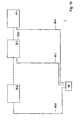
- Fig. 1a a first embodiment of a system according to the invention is shown.
- This system comprises multiple registration devices. This involves both person registration devices and goods registration devices.
- the system comprises a theft security system 2 which is provided with two transceiver devices 4, 6, disposed at two passages, respectively.
- the transceiver devices 4, 6 are each of a type known per se, for detecting antitheft labels which in this example pass the passages 8, 10.
- the system comprises a person registration device in the form of a person identification and/or registration system 14, known per se, disposed at a passage 12, for registering or identifying persons who pass the passage 12.
- the passages 8 and 10 are passages of a store 16.0, via which customers can enter and leave the store.
- the passage 12 is a passage for the personnel of the store 16.0.
- the person identification system 14 is intended for registering the times when identified employees enter the store and leave it again through passage 12.
- the passage 12 can be closed off from shopping space 20 by a door 18.
- the system further comprises two cash deck blocks 22, 24, known per se, which are each provided with a device 36, 38, respectively, for scanning goods to be checked out, and with deactivation devices 30, 32, respectively, for deactivating antitheft labels that may be attached to the goods.
- All registration devices such as the person and goods registration systems, can be provided with identification codes, with which the devices and systems mentioned are identifiable within the system.
- the system of the store 16.0 further comprises a local control device 26 which is connected via the communication device 28 with the antitheft system 4, the person identification system 14 and the cash deck blocks 22, 24.
- the system further comprises a central control device 48.
- Both the local control device 26 and the central control device 48 are connected with the communication device 30.n in order that the local control device 26 and the central control device 48 can exchange real-time information, i.e., real-time data, with each other.
- Fig. 1b further, other stores 16.1, 16.2, ... 16.n are indicated. Each of these stores is provided with person and/or goods registration devices, as well as a local control device 26 such as this has been discussed in connection with the store 16.0.
- These local control devices 26 are connected via the communication device 30.1 to 30.n with the central control device 48.
- the system is adapted for real-time transmission, from the local control device 26 to the central control device 48, of real-time information about the antitheft labels detected by the antitheft system 4, 6. Further, the system is adapted for real-time transmission from the local control device to the central control device of diagnostic information about the operation of the above-mentioned persons and goods identification devices 4, 6, 14, 22, 24. This diagnostic information can also relate to the number of alarms, etc. Naturally, false alarms are to be inputted by hand. This can be done, in this example, at the local control device 26, designed as a computer.
- the system is also adapted for transmitting from the local control device to the central control device real-time information about the goods registered at the cash deck blocks and for transmitting from the central control device to the local control device real-time information for modifying settings of the above-mentioned devices 4, 6, 14, 22, 24 and further for operating these devices.
- To be considered here is, for instance, adjustment of the sensitivity of the transceiver devices 4, 6, etc.
- the system is further adapted for real-time transmission from the local control device to the central control device of real-time information about the registered or identified persons. This involves information obtained by means of the device 14. Also, the system is provided with a plurality of groups of registration devices. In this example, all registration devices included in the store belong to a group. As already set out above, each registration device of a group of the registration devices is connected with a local control device 26.
- the central control device is adapted for statistically processing the diagnostic information, the information about the detected antitheft labels, the information about the registered goods and/or the information about the registered or identified goods. It further holds that the system is adapted for groupwise processing the diagnostic information, the information about the detected antitheft labels, the information about the registered goods and/or the information about the registered or identified persons. It also holds that the system is adapted for processing in combination the information obtained per group. It holds, furthermore, that the system is further adapted for transmitting from the local control device to the central control device information about the identity of an employee operating a cash deck block. In addition, it holds that the system is further adapted for transmitting information about the location of a group from the local control device to the central control device.
- the central control device comprises a display, the system being designed such that at least the following images can be shown on the display.
- Fig. 2 shows a first image.
- Fig. 2 shows a menu where, for instance with a mouse, respective icons Customers, EAS system (Electronic Antitheft System), POS (Point-of-Sale), EAS quality and Sourcetagging can be selected. If by means of the mouse the icon Customers is activated, figure 3 appears on the screen.
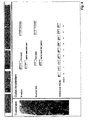
- Fig. 3 shows inter alia all customers who have visited the stores 16.0 to 16.n this week. These customers have been registered by the transceivers 4, 6, which, in this example, are additionally adapted such that they can register a person who enters the store via the passage 8 or 10.
- FIG. 4 When subsequently clicking on, for instance, Amsterdam with the mouse, the screen according to Fig. 4 appears, in which further information is shown regarding the store in Amsterdam about the number of visitors, the buy/visit ratio discussed earlier, and the percentage of the total number of visitors spread over the day.
- the screen of Fig. 2 When in the screen of Fig. 2 the icon EAS is energized by means of the mouse, the screen according to Fig. 5 appears. For all stores, this screen shows real-time the number of alarms caused by antitheft labels and the number of actual thefts of goods.
- a bar diagram a distinction is made between alarms caused by a so-called sticker tag and alarms caused by a wafer. This distinction can be carried out in an automatic manner when, for instance, the sticker tag has a different resonance than the wafer.
- the number of alarms is indicated not only for this week but also for the four preceding weeks. Further, as said, a distinction is made between the number of alarms and the number of thefts.
- Fig. 5 Indicated furthermore in Fig. 5 are the five best stores, i.e., where according to a predetermined criterion the least number of alarms and thefts occur. Also indicated are the five worst stores, where, according to a predetermined criterion, apparently most alarms and thefts occur. The newcomers among the five worst stores in this case are Amsterdam and Brussels, colored differently. When by means of the mouse for instance the icon Amsterdam is clicked, the fig. 6 appears. Fig. 6 shows the number of detected antitheft labels. Thus, it appears that in the current week, there have been 46 alarms. In the week before, there were 25 alarms. It also appears that the number of alarms that was due to a customer leaving the store was 64% of the total number of alarms.
- an employee should enter at the local control device 26 in respect of each alarm whether it went off for a customer entering the store or one leaving the store. It is further indicated to what extent the number of alarms this week is higher compared with last week. An 84% increase is involved here. Naturally, an alarm does not necessarily involve theft. Against 'thefts' it is indicated that there were five thefts this week and one theft last week. This, too, cannot be indicated until an employee has checked whether theft is actually involved. The information in question is again entered manually at the local control device 26.
- the store can have a number of passages. Thus, the store can have a passage adjacent a restaurant, a passage for the personnel, a passage to parking facilities, etc. On the screen, it is then also indicated at which passages the least number of alarms are caused and at which passages most alarms are caused. Naturally, this means that at each of these passages a security device 4, 6 is disposed.
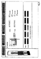
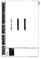
- Fig. 7 When in the menu of Fig. 2 the icon POS is energized, the screen according to Fig. 7 is depicted. In this screen, two choices can be made, viz. 'Information on deactivation' and 'Information on transaction'. When 'Information on deactivation' is energized, the screen of Fig. 8 appears. In this screen, it is shown for all stores together that this week 80 goods have been deactivated but not scanned. Possibly, therefore, these 80 goods have been misappropriated by employees. It is also indicated that in the week before, this happened only 68 times. Accordingly, a 17.6% increase is involved, as is clearly shown. The screen also shows the number of cases in which goods have been scanned without being deactivated.
- That no deactivation has taken place can be derived on the basis of the number of alarms at the entrance. Thus, it appears that in this week, this has occurred 471 times, compared with 369 times in the week before. It is indicated that a 27.6% increase is involved. When a commodity is scanned but not deactivated, this can point to failure on the part of an employee, failure of a deactivation device, etc. It is further also indicated when goods are deactivated after closing time 'deactivation after closing'. This may also point to possibly fraudulent acts on the part of employees. It appears that this happened 45 times this week, and 55 times last week. A decrease of 18%.
- the five best stores according to a predetermined criterion are designated again and in a lower row the five worst stores according to a predetermined criterion.
- detail information about the store in question can be obtained.
- the icon Amsterdam is energized, the screen according to Fig. 9 appears.
- the number of times of 'deactivation no scanning' is indicated for this week and the week before. There proves to be a 50% increase.
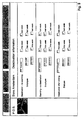
- an identification number of an employee (529-1489), against which the number of times that he or she has deactivated without scanning this week (4 times) and the week before (3 times). Similarly, this is indicated for an employee having identification number 529-0251.
- the number of times of 'scanning - no deactivation' for this week and last week is indicated. These numbers are likewise specified per employee, in this case for the employee having the identification number 529-8219, and for the employee having the identification number 529-6331. Also indicated for the Amsterdam store is the number of deactivations after closing time: 7 this week and 5 last week. This time a 40% increase is involved, as is also indicated. It is also indicated again per employee how many goods he has deactivated this week and last week after closing time.
- Fig. 7 When in Fig. 7 'Information on transactions' is selected, the screen according to Fig. 10 appears. Again, a number of icons are visible, which in this example are indicated through bars which can be energized to select particular types of transactions.
- a distinction can be made between goods which have been paid for at the cash deck in cash, via a pin code, with a credit card, etc. It can also be established per store, per cash deck and/or per employee whether goods have been taken back, etc. Such possibilities can each be further analyzed under 'select transaction type'.
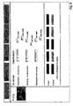
- Fig. 2 When in Fig. 2 the icon 'EAS quality' is energized, the screen according to Fig. 11 is shown. In this screen, per store, various information is shown, in this example about the theft security system. Thus, for the Berlin store, on May 3, 1999 from 1.05 p.m to 9.05 p.m. the system in question appears to have been switched off for the entrances 1, 2, 3 and 4. For Prague, it appears that on May 6, 1999, the person identification device 14 at the entrance 12 was defective all day.
- screens may be shown on the basis of which by means of mouse operations and the like settings of the various devices can be changed, devices can be switched on and off, etc. It is also possible by means of the central control device 28 to control the registration devices in question remotely. It is also possible to determine the system configuration remotely. This can here involve the number of antennas, the type of antenna and the width of a passage. It is also possible to change settings of a system remotely. To be considered here are the sensitivity of the detection at a passage, optimizing the system for detecting particular types of labels, setting the length of a period during which a lamp of a theft security system continues to burn when an alarm goes off, etc.
- Such lamps, alarms and the like can be checked remotely. It is even possible via the central control device to download updates of software to the local control device, which updates may thereupon be remotely implemented in the theft security system, the cash deck block, the person identification and registration system, etc. Also, the above-discussed information transmitted from the local control devices to the central control device can be processed in combination for obtaining alarm trends, profiles, etc. It will be clear that on a screen coupled to a local control device information can be shown according to a format analogous to the format as discussed above for the central control system. Naturally, the information on the local systems applies primarily only for information coming from the local system.
- identification code also relates to a system provided with a local control device without this being provided with explicitly provided identification codes because it is inherently known what systems are involved in this case.
- identification code also encompasses the individual connections between the systems and the control device.
- the system can also be equipped with possibilities of registering goods and persons. This is understood to include cameras, with which real-time a situation around a detection system is observed. Such variants are all understood to fall within the scope of the invention.
Landscapes
- Physics & Mathematics (AREA)
- Business, Economics & Management (AREA)
- General Physics & Mathematics (AREA)
- Engineering & Computer Science (AREA)
- Accounting & Taxation (AREA)
- Computer Security & Cryptography (AREA)
- Automation & Control Theory (AREA)
- Electromagnetism (AREA)
- General Business, Economics & Management (AREA)
- Strategic Management (AREA)
- Finance (AREA)
- Theoretical Computer Science (AREA)
- Economics (AREA)
- Entrepreneurship & Innovation (AREA)
- Development Economics (AREA)
- Emergency Management (AREA)
- Human Resources & Organizations (AREA)
- Marketing (AREA)
- Operations Research (AREA)
- Quality & Reliability (AREA)
- Tourism & Hospitality (AREA)
- Burglar Alarm Systems (AREA)
- Alarm Systems (AREA)
Description
- The invention relates to a system comprising at least one person and/or goods registration device such as a theft security system comprising at least one transceiver device, set up at a passage, for detecting antitheft labels that pass the passage, a person identification and/or registration system, set up at a passage, for registering or identifying persons who pass the passage and/or a cash deck block for registering goods to be checked out by, for instance, scanning, and optionally deactivating or removing antitheft labels attached to the goods.
- Such a system is known from
US 5,745,036 . Such a system is often placed in stores, such as department stores, where customers themselves can take the merchandise to be purchased from the position where it is displayed to a cash deck to pay for it. In such stores, it is possible to reach the exit of the store without visiting a cash deck to check out the merchandise. It is therefore fairly easy to steal, since, when leaving the store, the merchandise can be inconspicuously taken along, for instance hidden in a bag, without being paid for. To be able to discover theft of merchandise, a number of articles are provided with antitheft labels. The antitheft labels are so designed that when passing a passage, in this case the exit, a transceiver device set up there can detect the antitheft label. When the transceiver device detects an antitheft label, an alarm goes off. The alarm can be a visible alarm, such as, for instance, a flashing or rotating light attracting attention, or an audible alarm, such as, for instance, a siren. A security officer is alarmed by the alarm and will try to find the antitheft label that has been detected by the theft security system and proceed to stop a customer to prevent theft. When a customer checks out an article that is fitted with an antitheft label, the antitheft label, after payment, will be either removed from the article by the employee at the cash deck, or be deactivated. The transceiver device can no longer detect the antitheft label then. The customer can leave the store without an alarm going off. - The object of the invention is to improve the known system. The system according to the invention is characterized in that the at least one device is connected with a local control device for providing a communication connection between the at least one device and the local control device, the system further comprising a central control device which is connected with the local control device for exchanging data between the local control device and the central control device, the system being adapted for transmitting from the local control device to the central control device diagnostic information about the operation of the at least one device, for transmitting from the local control device to the central control device information about detected antitheft labels, for transmitting from the local control device to the central control device information about the registered goods, and/or for transmitting from the local control device to the central control device information about the registered or identified persons characterized in that the system is further adapted for transmitting from the central control device to the local control device information for changing settings of the at least one device and/or operating the at least one device.
- This central control device may be located, for instance, at a main office. At the central control device, information can be collected from various local control devices. By means of this system, for instance, a central control device at a main office in Amsterdam can be provided with real-time information about theft security systems in, for instance, London, Brussels, Paris, Madrid, etc.
- In order to obtain a better and more complete insight into the possibilities of the system according to the invention, all will be further elucidated with reference to the drawing. In the drawing:
-
Fig. 1a schematically shows a first possible embodiment of a system according to the invention; -
Fig. 1b schematically shows a second possible embodiment of a system according to the invention; and -
Figs. 2 to 12 respectively show screen layout of a display of the central control device of the system according toFig. 1 . - In
Fig. 1a a first embodiment of a system according to the invention is shown. This system comprises multiple registration devices. This involves both person registration devices and goods registration devices. More particularly, the system comprises atheft security system 2 which is provided with twotransceiver devices transceiver devices passages - Further, the system comprises a person registration device in the form of a person identification and/or
registration system 14, known per se, disposed at apassage 12, for registering or identifying persons who pass thepassage 12. In this example, thepassages passage 12 is a passage for the personnel of the store 16.0. Accordingly, theperson identification system 14 is intended for registering the times when identified employees enter the store and leave it again throughpassage 12. Thepassage 12 can be closed off fromshopping space 20 by adoor 18. - The system further comprises two
cash deck blocks device deactivation devices - The system of the store 16.0 further comprises a
local control device 26 which is connected via thecommunication device 28 with theantitheft system 4, theperson identification system 14 and the cash deck blocks 22, 24. - According to
Fig. 1b , the system further comprises acentral control device 48. Both thelocal control device 26 and thecentral control device 48 are connected with the communication device 30.n in order that thelocal control device 26 and thecentral control device 48 can exchange real-time information, i.e., real-time data, with each other. The communication device 30.n (with n=1,2,3,...) can consist of a telephone connection, Internet, a wireless connection, etc. InFig. 1b , further, other stores 16.1, 16.2, ... 16.n are indicated. Each of these stores is provided with person and/or goods registration devices, as well as alocal control device 26 such as this has been discussed in connection with the store 16.0. Theselocal control devices 26 are connected via the communication device 30.1 to 30.n with thecentral control device 48. - For each of the stores, it holds that the system is adapted for real-time transmission, from the
local control device 26 to thecentral control device 48, of real-time information about the antitheft labels detected by theantitheft system goods identification devices local control device 26, designed as a computer. The system is also adapted for transmitting from the local control device to the central control device real-time information about the goods registered at the cash deck blocks and for transmitting from the central control device to the local control device real-time information for modifying settings of the above-mentioneddevices transceiver devices - The system is further adapted for real-time transmission from the local control device to the central control device of real-time information about the registered or identified persons. This involves information obtained by means of the
device 14. Also, the system is provided with a plurality of groups of registration devices. In this example, all registration devices included in the store belong to a group. As already set out above, each registration device of a group of the registration devices is connected with alocal control device 26. - As will be set out in more detail hereinafter, the central control device is adapted for statistically processing the diagnostic information, the information about the detected antitheft labels, the information about the registered goods and/or the information about the registered or identified goods. It further holds that the system is adapted for groupwise processing the diagnostic information, the information about the detected antitheft labels, the information about the registered goods and/or the information about the registered or identified persons. It also holds that the system is adapted for processing in combination the information obtained per group. It holds, furthermore, that the system is further adapted for transmitting from the local control device to the central control device information about the identity of an employee operating a cash deck block. In addition, it holds that the system is further adapted for transmitting information about the location of a group from the local control device to the central control device.
- The above-mentioned measures have as a consequence that the central control device comprises a display, the system being designed such that at least the following images can be shown on the display.
Fig. 2 shows a first image.Fig. 2 shows a menu where, for instance with a mouse, respective icons Customers, EAS system (Electronic Antitheft System), POS (Point-of-Sale), EAS quality and Sourcetagging can be selected. If by means of the mouse the icon Customers is activated,figure 3 appears on the screen.Fig. 3 shows inter alia all customers who have visited the stores 16.0 to 16.n this week. These customers have been registered by thetransceivers passage Fig. 3 ), 481,050 persons were registered. On the screen it is accordingly indicated that an increase of 30.7% is involved. Also indicated on the screen is how many of the visits are in effect converted into a transaction. The buy/visit ratio indicates 39%. This information can be obtained on the basis of the articles scanned at the cash deck block and in combination with the persons who entered the store, registered at thepassages - This example involves stores inter alia in London, Madrid, Paris, Brussels, Berlin, Vienna, Cairo, Amsterdam, Stockholm, etc. The five stores that sold best are indicated in the upper row, while the five stores that sold worst are indicated in the lower row. Newcomers in a row can be indicated by means of colors. In this example, Amsterdam and Stockholm are represented in a different manner, which means that these are new in the row of five worst stores.
- When subsequently clicking on, for instance, Amsterdam with the mouse, the screen according to
Fig. 4 appears, in which further information is shown regarding the store in Amsterdam about the number of visitors, the buy/visit ratio discussed earlier, and the percentage of the total number of visitors spread over the day. - When in the screen of
Fig. 2 the icon EAS is energized by means of the mouse, the screen according toFig. 5 appears. For all stores, this screen shows real-time the number of alarms caused by antitheft labels and the number of actual thefts of goods. In a bar diagram a distinction is made between alarms caused by a so-called sticker tag and alarms caused by a wafer. This distinction can be carried out in an automatic manner when, for instance, the sticker tag has a different resonance than the wafer. In the example of the bar diagram, the number of alarms is indicated not only for this week but also for the four preceding weeks. Further, as said, a distinction is made between the number of alarms and the number of thefts. This last must be inputted manually by a n employee when, upon an alarm, he has established whether theft is involved. This data can be inputted manually at thelocal control device 26. As is clear, both the number of alarms of this week and the number of alarms of the week before is indicated. Also indicated is the rise in the number of alarms. The same holds for the number of thefts. - Indicated furthermore in
Fig. 5 are the five best stores, i.e., where according to a predetermined criterion the least number of alarms and thefts occur. Also indicated are the five worst stores, where, according to a predetermined criterion, apparently most alarms and thefts occur. The newcomers among the five worst stores in this case are Amsterdam and Brussels, colored differently. When by means of the mouse for instance the icon Amsterdam is clicked, thefig. 6 appears.Fig. 6 shows the number of detected antitheft labels. Thus, it appears that in the current week, there have been 46 alarms. In the week before, there were 25 alarms. It also appears that the number of alarms that was due to a customer leaving the store was 64% of the total number of alarms. To be able to distinguish between incoming and outgoing alarms, an employee should enter at thelocal control device 26 in respect of each alarm whether it went off for a customer entering the store or one leaving the store. It is further indicated to what extent the number of alarms this week is higher compared with last week. An 84% increase is involved here. Naturally, an alarm does not necessarily involve theft. Against 'thefts' it is indicated that there were five thefts this week and one theft last week. This, too, cannot be indicated until an employee has checked whether theft is actually involved. The information in question is again entered manually at thelocal control device 26. In this example, the store can have a number of passages. Thus, the store can have a passage adjacent a restaurant, a passage for the personnel, a passage to parking facilities, etc. On the screen, it is then also indicated at which passages the least number of alarms are caused and at which passages most alarms are caused. Naturally, this means that at each of these passages asecurity device - When in the menu of
Fig. 2 the icon POS is energized, the screen according toFig. 7 is depicted. In this screen, two choices can be made, viz. 'Information on deactivation' and 'Information on transaction'. When 'Information on deactivation' is energized, the screen ofFig. 8 appears. In this screen, it is shown for all stores together that thisweek 80 goods have been deactivated but not scanned. Possibly, therefore, these 80 goods have been misappropriated by employees. It is also indicated that in the week before, this happened only 68 times. Accordingly, a 17.6% increase is involved, as is clearly shown. The screen also shows the number of cases in which goods have been scanned without being deactivated. That no deactivation has taken place can be derived on the basis of the number of alarms at the entrance. Thus, it appears that in this week, this has occurred 471 times, compared with 369 times in the week before. It is indicated that a 27.6% increase is involved. When a commodity is scanned but not deactivated, this can point to failure on the part of an employee, failure of a deactivation device, etc. It is further also indicated when goods are deactivated after closing time 'deactivation after closing'. This may also point to possibly fraudulent acts on the part of employees. It appears that this happened 45 times this week, and 55 times last week. A decrease of 18%. Also, in an upper row the five best stores according to a predetermined criterion are designated again and in a lower row the five worst stores according to a predetermined criterion. By clicking on one of the stores again, detail information about the store in question can be obtained. When thus the icon Amsterdam is energized, the screen according toFig. 9 appears. For the Amsterdam store, the number of times of 'deactivation no scanning' is indicated for this week and the week before. There proves to be a 50% increase. Also indicated is an identification number of an employee (529-1489), against which the number of times that he or she has deactivated without scanning this week (4 times) and the week before (3 times). Similarly, this is indicated for an employee having identification number 529-0251. - Also, again for the Amsterdam store, the number of times of 'scanning - no deactivation' for this week and last week is indicated. These numbers are likewise specified per employee, in this case for the employee having the identification number 529-8219, and for the employee having the identification number 529-6331. Also indicated for the Amsterdam store is the number of deactivations after closing time: 7 this week and 5 last week. This time a 40% increase is involved, as is also indicated. It is also indicated again per employee how many goods he has deactivated this week and last week after closing time.
- When in
Fig. 7 'Information on transactions' is selected, the screen according toFig. 10 appears. Again, a number of icons are visible, which in this example are indicated through bars which can be energized to select particular types of transactions. Thus a distinction can be made between goods which have been paid for at the cash deck in cash, via a pin code, with a credit card, etc. It can also be established per store, per cash deck and/or per employee whether goods have been taken back, etc. Such possibilities can each be further analyzed under 'select transaction type'. - When in
Fig. 2 the icon 'EAS quality' is energized, the screen according toFig. 11 is shown. In this screen, per store, various information is shown, in this example about the theft security system. Thus, for the Berlin store, on May 3, 1999 from 1.05 p.m to 9.05 p.m. the system in question appears to have been switched off for theentrances person identification device 14 at theentrance 12 was defective all day. - Also, it appears a table has been included for the
deactivation devices cash decks numbers cash deck number 8 was switched off from 11.07 a.m. to 6.36 p.m on May 3, 1999. - When in
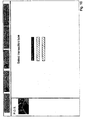
Fig. 2 , finally, the icon 'sourcetagging' is energized, the screen according toFig. 12 appears. - It is often agreed with suppliers of products that they provide, for instance, 75% of their products with an identification label. For Adidas shirt 'Agassi' with
product code 71632415, this is 75% as shown inFig. 12 , based on information from the cash deck blocks 22, 24. This information consists, for instance, of a scannedproduct code 71632415. Also, it is then inputted at the cash deck whether the product in question is found to have an antitheft label. In this case, it is found that 34% of the scanned products withproduct code 71632415 are provided with such a label.Fig. 12 accordingly makes clear that this is far below the required level agreed upon with the supplier. This can be a reason to contact the supplier. For other products with other product codes, similar information is shown on the screen according toFig. 12 . - The invention is not limited in any way to the above-outlined exemplary embodiments. Thus, screens may be shown on the basis of which by means of mouse operations and the like settings of the various devices can be changed, devices can be switched on and off, etc. It is also possible by means of the
central control device 28 to control the registration devices in question remotely. It is also possible to determine the system configuration remotely. This can here involve the number of antennas, the type of antenna and the width of a passage. It is also possible to change settings of a system remotely. To be considered here are the sensitivity of the detection at a passage, optimizing the system for detecting particular types of labels, setting the length of a period during which a lamp of a theft security system continues to burn when an alarm goes off, etc. Also, such lamps, alarms and the like can be checked remotely. It is even possible via the central control device to download updates of software to the local control device, which updates may thereupon be remotely implemented in the theft security system, the cash deck block, the person identification and registration system, etc. Also, the above-discussed information transmitted from the local control devices to the central control device can be processed in combination for obtaining alarm trends, profiles, etc. It will be clear that on a screen coupled to a local control device information can be shown according to a format analogous to the format as discussed above for the central control system. Naturally, the information on the local systems applies primarily only for information coming from the local system. - The term identification code also relates to a system provided with a local control device without this being provided with explicitly provided identification codes because it is inherently known what systems are involved in this case. The term identification code also encompasses the individual connections between the systems and the control device. With the system, in all cases, the number of detections of antitheft labels per unit time or per predetermined period can be updated real-time, thus enabling real-time intervention when, for instance, a predetermined threshold value, adjustable according to circumstances, has been exceeded. This information can be disclosed at the local control device and/or the central control device in a manner known per se. The threshold value can be set per antitheft system and even per transceiver device. When a large number (or too large a number) of antitheft labels are being detected, this can then be brought real-time to the attention of the employees on, for instance, cash deck blocks from the local and/or central control device. What matters primarily is that the number is real-time registrable and transmittable to management. However, as discussed, the system can also be equipped with possibilities of registering goods and persons. This is understood to include cameras, with which real-time a situation around a detection system is observed. Such variants are all understood to fall within the scope of the invention.
Claims (9)
- A system comprising at least one person and/or goods registration device such as a theft security system comprising at least one transceiver device, set up at a passage, for detecting antitheft labels that pass the passage, a person identification and/or registration system, set up at a passage, for registering or identifying persons who pass the passage and/or a cash deck block for registering goods to be checked out by, for instance, scanning, and optionally deactivating or removing antitheft labels attached to the goods, characterized in that the at least one device is connected with a local control device for providing a communication connection between the at least one device and the local control device, the system further comprising a central control device which is connected with the local control device for exchanging data between the local control device and the central control device, the system being adapted for transmitting from the local control device to the central control device diagnostic information about the operation of the at least one device, for transmitting from the local control device to the central control device information about detected antitheft labels, for transmitting from the local control device to the central control device information about the registered goods, and/or for transmitting from the local control device to the central control device information about the registered or identified persons characterized in that the system is further adapted for transmitting from the central control device to the local control device information for changing settings of the at least one device and/or operating the at least one device.
- A system according to claim 1, characterized in that the system is adapted for transmitting from the local control device to the central control device the information about the detected antitheft labels, for transmitting from the local control device to the central control device the diagnostic information about the operation of the at least one device, for transmitting from the local control device to the central control device information about the registered goods, and for transmitting from the central control device to the local control device information for changing settings of the at least one device and/or operating the at least one device.
- A system according to claim 2, characterized in that the system is further adapted for transmitting from the local control device to the central control device information about the registered or identified persons.
- A system according to any one of the preceding claims 1-3, characterized in that the system comprises a plurality of groups of registration devices, each registration device of a group of registration devices being connected with a local control device.
- A system according to any one of the preceding claims 1-4, characterized in that the central control device is adapted for statistically processing the diagnostic information, the information about the detected antitheft labels, the information about the registered goods and/or the information about the registered or identified persons.
- A system according to claims 4 and 5, characterized in that the system is adapted for groupwise processing the diagnostic information, the information about the detected antitheft labels, the information about the registered goods and/or the information about the registered or identified persons.
- A system according to claim 6, characterized in that the system is adapted for processing in combination the information obtained per group.
- A system according to any one of claims 1-7, characterized in that the system is further adapted for transmitting from the local control device to the central control device information about the identity of an employee which operates a cash deck block.
- A system according to claim 6 or 7, characterized in that the system is further adapted for transmitting information about the location of a group from the local control device to the central control device.
Priority Applications (1)
| Application Number | Priority Date | Filing Date | Title |
|---|---|---|---|
| EP08168002A EP2093728B1 (en) | 1999-10-08 | 2000-10-09 | Real-time system for monitoring theft protection |
Applications Claiming Priority (3)
| Application Number | Priority Date | Filing Date | Title |
|---|---|---|---|
| NL1013245A NL1013245C2 (en) | 1999-10-08 | 1999-10-08 | Open system technology. |
| EP04075103A EP1420378B1 (en) | 1999-10-08 | 2000-10-09 | Real-time system for monitoring theft protection |
| EP20000973258 EP1226565B1 (en) | 1999-10-08 | 2000-10-09 | Real-time system for monitoring theft protection |
Related Parent Applications (1)
| Application Number | Title | Priority Date | Filing Date |
|---|---|---|---|
| EP04075103A Division EP1420378B1 (en) | 1999-10-08 | 2000-10-09 | Real-time system for monitoring theft protection |
Related Child Applications (1)
| Application Number | Title | Priority Date | Filing Date |
|---|---|---|---|
| EP08168002A Division EP2093728B1 (en) | 1999-10-08 | 2000-10-09 | Real-time system for monitoring theft protection |
Publications (2)
| Publication Number | Publication Date |
|---|---|
| EP1768073A1 EP1768073A1 (en) | 2007-03-28 |
| EP1768073B1 true EP1768073B1 (en) | 2008-11-26 |
Family
ID=19770016
Family Applications (5)
| Application Number | Title | Priority Date | Filing Date |
|---|---|---|---|
| EP04075103A Expired - Lifetime EP1420378B1 (en) | 1999-10-08 | 2000-10-09 | Real-time system for monitoring theft protection |
| EP20000973258 Expired - Lifetime EP1226565B1 (en) | 1999-10-08 | 2000-10-09 | Real-time system for monitoring theft protection |
| EP08168002A Expired - Lifetime EP2093728B1 (en) | 1999-10-08 | 2000-10-09 | Real-time system for monitoring theft protection |
| EP04075106A Expired - Lifetime EP1411484B1 (en) | 1999-10-08 | 2000-10-09 | Real-time system for monitoring theft protection |
| EP06077186A Expired - Lifetime EP1768073B1 (en) | 1999-10-08 | 2000-10-09 | Real-time system for monitoring theft protection |
Family Applications Before (4)
| Application Number | Title | Priority Date | Filing Date |
|---|---|---|---|
| EP04075103A Expired - Lifetime EP1420378B1 (en) | 1999-10-08 | 2000-10-09 | Real-time system for monitoring theft protection |
| EP20000973258 Expired - Lifetime EP1226565B1 (en) | 1999-10-08 | 2000-10-09 | Real-time system for monitoring theft protection |
| EP08168002A Expired - Lifetime EP2093728B1 (en) | 1999-10-08 | 2000-10-09 | Real-time system for monitoring theft protection |
| EP04075106A Expired - Lifetime EP1411484B1 (en) | 1999-10-08 | 2000-10-09 | Real-time system for monitoring theft protection |
Country Status (7)
| Country | Link |
|---|---|
| US (2) | US7046149B1 (en) |
| EP (5) | EP1420378B1 (en) |
| AU (1) | AU1178701A (en) |
| DE (4) | DE60040940D1 (en) |
| ES (5) | ES2318661T3 (en) |
| NL (1) | NL1013245C2 (en) |
| WO (1) | WO2001027892A1 (en) |
Families Citing this family (15)
| Publication number | Priority date | Publication date | Assignee | Title |
|---|---|---|---|---|
| WO2002080123A1 (en) * | 2001-03-30 | 2002-10-10 | Bernhard Hesse | Method for automatically monitoring and managing articles |
| US20050102183A1 (en) * | 2003-11-12 | 2005-05-12 | General Electric Company | Monitoring system and method based on information prior to the point of sale |
| NL1026951C2 (en) | 2004-09-02 | 2006-03-09 | Nedap Nv | Electronic theft detection system, as well as a data processing system and a method for preventing theft of articles. |
| US20070164845A1 (en) | 2004-12-21 | 2007-07-19 | Checkpoint Systems, Inc. | System and method for monitoring security systems |
| US7603184B2 (en) | 2005-09-12 | 2009-10-13 | Abl Ip Holding Llc | Light management system having networked intelligent luminaire managers |
| WO2007044445A2 (en) | 2005-10-05 | 2007-04-19 | Guardian Networks, Llc | A method and system for remotely monitoring and controlling field devices with a street lamp elevated mesh network |
| US7782207B2 (en) * | 2007-06-12 | 2010-08-24 | Checkpoint Systems, Inc. | Comprehensive theft security system |
| US8140276B2 (en) | 2008-02-27 | 2012-03-20 | Abl Ip Holding Llc | System and method for streetlight monitoring diagnostics |
| CA2773798A1 (en) | 2009-09-09 | 2011-03-17 | Absolute Software Corporation | Alert for real-time risk of theft or loss |
| WO2011035302A1 (en) * | 2009-09-21 | 2011-03-24 | Checkpoint Systems, Inc. | Retail product tracking system, method, and apparatus |
| US8508367B2 (en) * | 2009-09-21 | 2013-08-13 | Checkpoint Systems, Inc. | Configurable monitoring device |
| NL2007029C2 (en) * | 2011-02-24 | 2012-08-27 | Cross Point B V | SYSTEM WITH ARTICLE-MONITORING DEVICE, ARTICLE-MONITORING DEVICE AND METHOD FOR VISUALIZING SET-UP INFORMATION. |
| JP6616210B2 (en) | 2016-02-29 | 2019-12-04 | 東芝テック株式会社 | Control apparatus and program for wireless tag reader |
| JP2018115060A (en) * | 2017-01-19 | 2018-07-26 | コニカミノルタ株式会社 | Post-processing device and image forming system |
| CN107689126A (en) * | 2017-07-28 | 2018-02-13 | 广东工业大学 | A kind of networking goods monitoring system based on acceleration detection |
Family Cites Families (6)
| Publication number | Priority date | Publication date | Assignee | Title |
|---|---|---|---|---|
| US4636950A (en) * | 1982-09-30 | 1987-01-13 | Caswell Robert L | Inventory management system using transponders associated with specific products |
| US4972504A (en) * | 1988-02-11 | 1990-11-20 | A. C. Nielsen Company | Marketing research system and method for obtaining retail data on a real time basis |
| US5151684A (en) * | 1991-04-12 | 1992-09-29 | Johnsen Edward L | Electronic inventory label and security apparatus |
| GB9202831D0 (en) * | 1992-02-11 | 1992-03-25 | Shanning Laser Systems Ltd | Security tag |
| WO1995030201A1 (en) * | 1994-05-02 | 1995-11-09 | Catalina Information Resources, Inc. | Method and apparatus for real-time tracking of retail sales of selected products |
| US5745036A (en) | 1996-09-12 | 1998-04-28 | Checkpoint Systems, Inc. | Electronic article security system for store which uses intelligent security tags and transaction data |
-
1999
- 1999-10-08 NL NL1013245A patent/NL1013245C2/en not_active IP Right Cessation
-
2000
- 2000-10-09 ES ES06077186T patent/ES2318661T3/en not_active Expired - Lifetime
- 2000-10-09 AU AU11787/01A patent/AU1178701A/en not_active Abandoned
- 2000-10-09 EP EP04075103A patent/EP1420378B1/en not_active Expired - Lifetime
- 2000-10-09 DE DE60040940T patent/DE60040940D1/en not_active Expired - Lifetime
- 2000-10-09 DE DE60032826T patent/DE60032826T2/en not_active Expired - Lifetime
- 2000-10-09 US US10/110,140 patent/US7046149B1/en not_active Expired - Lifetime
- 2000-10-09 EP EP20000973258 patent/EP1226565B1/en not_active Expired - Lifetime
- 2000-10-09 EP EP08168002A patent/EP2093728B1/en not_active Expired - Lifetime
- 2000-10-09 EP EP04075106A patent/EP1411484B1/en not_active Expired - Lifetime
- 2000-10-09 DE DE60010743T patent/DE60010743T2/en not_active Expired - Lifetime
- 2000-10-09 EP EP06077186A patent/EP1768073B1/en not_active Expired - Lifetime
- 2000-10-09 ES ES00973258T patent/ES2218239T3/en not_active Expired - Lifetime
- 2000-10-09 ES ES04075103T patent/ES2278268T3/en not_active Expired - Lifetime
- 2000-10-09 DE DE60033325T patent/DE60033325T2/en not_active Expired - Lifetime
- 2000-10-09 WO PCT/NL2000/000726 patent/WO2001027892A1/en active IP Right Grant
- 2000-10-09 ES ES08168002T patent/ES2378114T3/en not_active Expired - Lifetime
- 2000-10-09 ES ES04075106T patent/ES2278269T3/en not_active Expired - Lifetime
-
2006
- 2006-03-31 US US11/394,123 patent/US7405661B2/en not_active Expired - Fee Related
Also Published As
| Publication number | Publication date |
|---|---|
| DE60032826T2 (en) | 2007-08-16 |
| DE60010743T2 (en) | 2005-05-25 |
| EP1226565A1 (en) | 2002-07-31 |
| EP1768073A1 (en) | 2007-03-28 |
| US7046149B1 (en) | 2006-05-16 |
| NL1013245C2 (en) | 2001-04-10 |
| DE60010743D1 (en) | 2004-06-17 |
| DE60033325D1 (en) | 2007-03-22 |
| US20060290506A1 (en) | 2006-12-28 |
| ES2318661T3 (en) | 2009-05-01 |
| EP1411484A1 (en) | 2004-04-21 |
| EP1411484B1 (en) | 2007-02-07 |
| ES2278268T3 (en) | 2007-08-01 |
| US7405661B2 (en) | 2008-07-29 |
| EP1226565B1 (en) | 2004-05-12 |
| EP2093728A1 (en) | 2009-08-26 |
| EP2093728B1 (en) | 2011-11-30 |
| ES2278269T3 (en) | 2007-08-01 |
| WO2001027892A1 (en) | 2001-04-19 |
| ES2218239T3 (en) | 2004-11-16 |
| AU1178701A (en) | 2001-04-23 |
| DE60033325T2 (en) | 2007-11-22 |
| EP1420378B1 (en) | 2007-01-03 |
| ES2378114T3 (en) | 2012-04-09 |
| DE60040940D1 (en) | 2009-01-08 |
| DE60032826D1 (en) | 2007-02-15 |
| EP1420378A1 (en) | 2004-05-19 |
Similar Documents
| Publication | Publication Date | Title |
|---|---|---|
| US7405661B2 (en) | Real-time system for monitoring theft protection | |
| US7920063B2 (en) | RFID theft prevention system | |
| US8477033B2 (en) | Inventory control | |
| EP1817758B1 (en) | System and method for integrating point of sale and electronic article surveillance data | |
| US7239241B2 (en) | Method and system for inventory control | |
| US20190043002A1 (en) | Fitting Room Management and Occupancy Monitoring System | |
| US20100019905A1 (en) | System for inventory tracking and theft deterrence | |
| US8847761B1 (en) | Anonymous transaction tokens | |
| US8047434B2 (en) | Known loss data logging |
Legal Events
| Date | Code | Title | Description |
|---|---|---|---|
| PUAI | Public reference made under article 153(3) epc to a published international application that has entered the european phase |
Free format text: ORIGINAL CODE: 0009012 |
|
| 17P | Request for examination filed |
Effective date: 20061206 |
|
| AC | Divisional application: reference to earlier application |
Ref document number: 1226565 Country of ref document: EP Kind code of ref document: P Ref document number: 1420378 Country of ref document: EP Kind code of ref document: P |
|
| AK | Designated contracting states |
Kind code of ref document: A1 Designated state(s): DE ES FR GB NL |
|
| AX | Request for extension of the european patent |
Extension state: AL LT LV MK RO SI |
|
| 17Q | First examination report despatched |
Effective date: 20071022 |
|
| AKX | Designation fees paid |
Designated state(s): DE ES FR GB NL |
|
| GRAP | Despatch of communication of intention to grant a patent |
Free format text: ORIGINAL CODE: EPIDOSNIGR1 |
|
| RIC1 | Information provided on ipc code assigned before grant |
Ipc: G07G 3/00 20060101ALI20080530BHEP Ipc: G07G 1/00 20060101ALI20080530BHEP Ipc: G08B 13/24 20060101AFI20080530BHEP |
|
| GRAS | Grant fee paid |
Free format text: ORIGINAL CODE: EPIDOSNIGR3 |
|
| GRAA | (expected) grant |
Free format text: ORIGINAL CODE: 0009210 |
|
| AC | Divisional application: reference to earlier application |
Ref document number: 1420378 Country of ref document: EP Kind code of ref document: P Ref document number: 1226565 Country of ref document: EP Kind code of ref document: P |
|
| AK | Designated contracting states |
Kind code of ref document: B1 Designated state(s): DE ES FR GB NL |
|
| REG | Reference to a national code |
Ref country code: GB Ref legal event code: FG4D |
|
| REF | Corresponds to: |
Ref document number: 60040940 Country of ref document: DE Date of ref document: 20090108 Kind code of ref document: P |
|
| REG | Reference to a national code |
Ref country code: ES Ref legal event code: FG2A Ref document number: 2318661 Country of ref document: ES Kind code of ref document: T3 |
|
| PLBE | No opposition filed within time limit |
Free format text: ORIGINAL CODE: 0009261 |
|
| STAA | Information on the status of an ep patent application or granted ep patent |
Free format text: STATUS: NO OPPOSITION FILED WITHIN TIME LIMIT |
|
| 26N | No opposition filed |
Effective date: 20090827 |
|
| REG | Reference to a national code |
Ref country code: FR Ref legal event code: PLFP Year of fee payment: 16 |
|
| REG | Reference to a national code |
Ref country code: FR Ref legal event code: PLFP Year of fee payment: 17 |
|
| REG | Reference to a national code |
Ref country code: FR Ref legal event code: PLFP Year of fee payment: 18 |
|
| REG | Reference to a national code |
Ref country code: FR Ref legal event code: PLFP Year of fee payment: 19 |
|
| PGFP | Annual fee paid to national office [announced via postgrant information from national office to epo] |
Ref country code: NL Payment date: 20180925 Year of fee payment: 19 |
|
| PGFP | Annual fee paid to national office [announced via postgrant information from national office to epo] |
Ref country code: DE Payment date: 20181019 Year of fee payment: 19 |
|
| PGFP | Annual fee paid to national office [announced via postgrant information from national office to epo] |
Ref country code: ES Payment date: 20181123 Year of fee payment: 19 Ref country code: GB Payment date: 20181019 Year of fee payment: 19 Ref country code: FR Payment date: 20181022 Year of fee payment: 19 |
|
| REG | Reference to a national code |
Ref country code: DE Ref legal event code: R119 Ref document number: 60040940 Country of ref document: DE |
|
| REG | Reference to a national code |
Ref country code: NL Ref legal event code: MM Effective date: 20191101 |
|
| PG25 | Lapsed in a contracting state [announced via postgrant information from national office to epo] |
Ref country code: DE Free format text: LAPSE BECAUSE OF NON-PAYMENT OF DUE FEES Effective date: 20200501 |
|
| PG25 | Lapsed in a contracting state [announced via postgrant information from national office to epo] |
Ref country code: NL Free format text: LAPSE BECAUSE OF NON-PAYMENT OF DUE FEES Effective date: 20191101 |
|
| GBPC | Gb: european patent ceased through non-payment of renewal fee |
Effective date: 20191009 |
|
| PG25 | Lapsed in a contracting state [announced via postgrant information from national office to epo] |
Ref country code: GB Free format text: LAPSE BECAUSE OF NON-PAYMENT OF DUE FEES Effective date: 20191009 Ref country code: FR Free format text: LAPSE BECAUSE OF NON-PAYMENT OF DUE FEES Effective date: 20191031 |
|
| REG | Reference to a national code |
Ref country code: ES Ref legal event code: FD2A Effective date: 20210301 |
|
| PG25 | Lapsed in a contracting state [announced via postgrant information from national office to epo] |
Ref country code: ES Free format text: LAPSE BECAUSE OF NON-PAYMENT OF DUE FEES Effective date: 20191010 |