EP1768005A2 - Verfahren und System zur Grafikverarbeitung in einem Überwachungssteuersystem - Google Patents
Verfahren und System zur Grafikverarbeitung in einem Überwachungssteuersystem Download PDFInfo
- Publication number
- EP1768005A2 EP1768005A2 EP06012736A EP06012736A EP1768005A2 EP 1768005 A2 EP1768005 A2 EP 1768005A2 EP 06012736 A EP06012736 A EP 06012736A EP 06012736 A EP06012736 A EP 06012736A EP 1768005 A2 EP1768005 A2 EP 1768005A2
- Authority
- EP
- European Patent Office
- Prior art keywords
- display
- objects
- equipment
- equipment unit
- operational components
- Prior art date
- Legal status (The legal status is an assumption and is not a legal conclusion. Google has not performed a legal analysis and makes no representation as to the accuracy of the status listed.)
- Granted
Links
Images




Classifications
-
- G—PHYSICS
- G05—CONTROLLING; REGULATING
- G05B—CONTROL OR REGULATING SYSTEMS IN GENERAL; FUNCTIONAL ELEMENTS OF SUCH SYSTEMS; MONITORING OR TESTING ARRANGEMENTS FOR SUCH SYSTEMS OR ELEMENTS
- G05B19/00—Program-control systems
- G05B19/02—Program-control systems electric
- G05B19/418—Total factory control, i.e. centrally controlling a plurality of machines, e.g. direct or distributed numerical control [DNC], flexible manufacturing systems [FMS], integrated manufacturing systems [IMS] or computer integrated manufacturing [CIM]
- G05B19/41875—Total factory control, i.e. centrally controlling a plurality of machines, e.g. direct or distributed numerical control [DNC], flexible manufacturing systems [FMS], integrated manufacturing systems [IMS] or computer integrated manufacturing [CIM] characterised by quality surveillance of production
-
- G—PHYSICS
- G05—CONTROLLING; REGULATING
- G05B—CONTROL OR REGULATING SYSTEMS IN GENERAL; FUNCTIONAL ELEMENTS OF SUCH SYSTEMS; MONITORING OR TESTING ARRANGEMENTS FOR SUCH SYSTEMS OR ELEMENTS
- G05B2219/00—Program-control systems
- G05B2219/30—Nc systems
- G05B2219/31—From computer integrated manufacturing till monitoring
- G05B2219/31472—Graphical display of process
-
- G—PHYSICS
- G05—CONTROLLING; REGULATING
- G05B—CONTROL OR REGULATING SYSTEMS IN GENERAL; FUNCTIONAL ELEMENTS OF SUCH SYSTEMS; MONITORING OR TESTING ARRANGEMENTS FOR SUCH SYSTEMS OR ELEMENTS
- G05B2219/00—Program-control systems
- G05B2219/30—Nc systems
- G05B2219/35—Nc in input of data, input till input file format
- G05B2219/35485—Library of images, pictures, select and modify each, compose them
-
- Y—GENERAL TAGGING OF NEW TECHNOLOGICAL DEVELOPMENTS; GENERAL TAGGING OF CROSS-SECTIONAL TECHNOLOGIES SPANNING OVER SEVERAL SECTIONS OF THE IPC; TECHNICAL SUBJECTS COVERED BY FORMER USPC CROSS-REFERENCE ART COLLECTIONS [XRACs] AND DIGESTS
- Y02—TECHNOLOGIES OR APPLICATIONS FOR MITIGATION OR ADAPTATION AGAINST CLIMATE CHANGE
- Y02P—CLIMATE CHANGE MITIGATION TECHNOLOGIES IN THE PRODUCTION OR PROCESSING OF GOODS
- Y02P90/00—Enabling technologies with a potential contribution to greenhouse gas [GHG] emissions mitigation
- Y02P90/02—Total factory control, e.g. smart factories, flexible manufacturing systems [FMS] or integrated manufacturing systems [IMS]
Definitions
- the present invention relates to supervisory control systems and to methods and systems for processing and displaying graphics therein.
- Supervisory control systems are used in the operation of plants, networks, hospitals, traffic regions as well as a large number of other facilities.
- these facilities include chemical plants and reactors.
- the supervisory control systems are used to monitor the operation and status of these facilities.
- the supervisory control systems generate a graphical display representative of the operational status of the facility being monitored and operators observe and control the equipment they are responsible for via operator stations using the supervisory control systems. Since the equipment units and the interrelations between them are shown in pictures, the operators are able to determine the status of the facilities by examining the graphical display.
- supervisory control systems are generally connected to a network. If too many requests are made by different display client at different stations, then the quantity of data being transferred could overload the network, crashing the system. Additionally, if any of the processes and status being monitored are time critical, the slowness of the system can be a problem to the facility controllers.
- a system and a method uses of a type-instance concept while also using standard graphics formats not designed for this supervisory control systems.
- the present invention provides superior levels of performance and footprint, despite the utilization of standard graphics formats.
- the method of the present invention generates a graphical display in a client display.
- the graphical display is representative of a current status of one or more operational components located in a plant, facility or process. There can be one or more types of operational components.
- a request for an update of the graphical display is made by the client display from a server.
- the server is in communication with the one or more operational components and the server generates one or more equipment unit objects, each of the one or more equipment unit objects representing one or more current parameters of one of the one or more operational components.
- the server transmits the one or more equipment unit objects to the client display over a network.
- the graphical display is generated by processing the transmitted one or more equipment unit objects with a picture object that describes a location of each of the one or more operational components in the graphical display and with one or more equipment symbol objects, each of the one or more equipment symbol objects defining a graphical representation in the graphical display of one of the one or more types of operational components.
- the method further includes displaying the graphical display.
- the graphical display reflects the one or more current parameters of the one or more operational components.
- the method further includes controlling the one or more operational components based on the graphical display.
- the equipment unit objects are smaller than the picture object and the equipment symbol objects.
- the present invention results in an efficient generation of a graphical display of a plant, facility or process, allowing for an improved supervisory control system.
- the method includes generating the graphical display by processing the one or more equipment unit objects with one or more equipment graphics list objects, each of the equipment graphics list objects listing a plurality of operational components.
- a supervisory control system for generating a graphical display representative of an operational status of one or more operational components.
- the system includes a server in communication with the one or more operational components via a network, wherein the server maintains one or more equipment unit objects, each of the one or more equipment unit objects having one or more parameters representative of the operational status of the one or more operational components.
- the operational components are monitored and controlled by a controller.
- the system further includes a client display in communication with the server that displays pictures representative of the status of the operational components.
- the display client stores one or more equipment symbol objects, each of the one or more equipment symbol objects defining a graphical representation of one of the one or more operational components in the graphical display, and stores a picture object that describes a location of each of the one or more operational components in the graphics display.
- These objects can be downloaded from the server at start up, can be stored at the display client or can be obtained during a first request for a graphical display from the server.
- the display client includes a standard means for requesting an update of the graphical display and for receiving one or more equipment unit objects from the server to the display client.
- a processor in the display client generates the graphical display by processing the one or more equipment unit objects with the picture object and with the one or more equipment symbol objects.
- the server updates the one or more equipment objects based on the operational status of the one or more operational components.
- the graphical display reflects the one or more current parameters of the one or more operational components.
- the supervisory control system includes means for controlling the one or more operational components based on the graphical display.
- FIG. 1 illustrates a supervisory control system monitoring a chemical plant.
- FIG. 2 illustrates one type of display that can be generated by a supervisory control system.
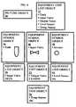
- FIGS. 3 and 4 illustrate an object model used by the supervisory control system in accordance with one aspect of the present invention.
- FIG. 5 illustrates the steps performed to process and generate a graphics display of a plant or facility in accordance with one aspect of the present invention.
- FIG. 6 illustrates an example of a supervisory control system monitoring a plurality of controllers.
- FIG. 1 illustrates a supervisory control system.
- the supervisory control system includes a server 12 monitoring a plant, facility or process 14.
- Various well known interface devices provide an interface from the various components of the facility 14 to the server 12. The number of interface devices depends on the number of parameters and pieces of equipment being monitored in the facility 14.
- a plurality of display clients 16, 18 and 20 are in communication with the server 12 via a network 22.
- the display clients include supervisory control systems that can be used to display a graphical display of the facility 14 that represents the operational status of the equipment in the facility 14.
- all of the graphical information required to display the graphical representation is transmitted from the server 12 to the requesting display client 16, 18 or 20 each time they need to generate a graphical display. If a large number of display clients request displays at the same time, the network 22 can crash. In any event, the generation of graphical displays by the display client can take a lot of time.
- supervisory control systems Any number of different types of plants or processes can be monitored by supervisory control systems.
- chemical plants and processes, semiconductor plants and processes, and reactor facilities can be, and are, monitored with supervisory control systems.
- FIG. 2 illustrates a display generated by a supervisory control system.
- a typical chemical plant is illustrated.
- the illustrated chemical plant includes tanks, valves and sensors.
- tank 22, sensor 24 and valve 26 are illustrated in FIG. 2.
- the picture generated by the supervisory control system consists of the graphical representations of selected equipment units in the plant or process being monitored.
- a typical picture shows 100 to 500 equipment units overall.
- the preferred style of displaying the picture is in two-dimensional schematics, although occasionally three-dimensional graphics are in use.
- each equipment unit is represented by a graphical object.
- the complexity of the graphical object may vary.
- Each equipment unit in the chemical plant has a series of attributes or properties. Some of the attributes or properties may change with time.
- the equipment, units are of a certain type, and the graphical representation of an equipment unit is of a certain type, too. For simplicity, we assume a 1:1 relation, though occasionally this may not be the case.
- the number of equipment types is surprisingly restricted.
- the number of equipment types in a large plant is in the range of 20 to 50 types.
- Each of the equipment types can have many different states, with each state having many different property values.
- the number of instances can get quite large. In some cases, one thousand instances for each equipment type can often be counted.
- graphics are generated in a supervisory control system by exploiting the special profile of supervisory control system pictures. By doing so, superior levels of performance and storage utilization are achieved by the system and method of the present invention.
- the present invention preferably uses an object model having several object types to model the plant or process.
- the object types used in accordance with one aspect of the present invention includes (1) an Equipment Unit object 36, (2) an Equipment Symbol object 34, (3) an Equipment Unit List object 32 and (4) a Picture object 30. These objects are illustrated in FIG. 3.
- the Equipment Unit object models the real world equipment units found in the facility 14.
- Each Equipment Unit object has a list of attributes or properties that describe the status of various parameters of a real world equipment unit. Some of the attributes or properties will change dynamically. Some of the attributes will stem from real world processes.
- a motor may have an Equipment Unit object that has many attributes. One such attribute may be the revolving speed of the motor which is measured by an interface device.
- Other attributes will be derived by formula.
- an average value of a parameter may be derived by the supervisory control system or by the device being monitored and that average value may be an attribute in the Equipment Unit object.
- the supervisory control system may calculate the average (calibrated) temperature of an array of temperature sensors.
- each Equipment Unit object may have a number of different possible states representing various operational states, standby states, inactive states or malfunctioning states. Each of these different states can be represented by an instance of the Equipment Unit object.
- a second object type in the object model is the Equipment Symbol.
- the Equipment Symbol object is the graphical representation of an equipment unit, including the graphical attributes of the graphics primitives used and the description of the outline of dynamic attributes. Any convenient graphics format could be used. For example, SVG can be used.
- a third object type is an Equipment Unit List.
- the Equipment Unit List object lists a group of components that are associated together. For example, a tank may have an input valve, an output valve, a temperature sensor and a level sensor working in conjunction with it.
- the Equipment Unit List object provides a list of all equipment that may be grouped together.
- a fourth object type is a Picture object.
- the Picture object is the container for instances of equipment representations with their positions within the picture. Thus every component in the facility 14 being monitored is represented in the Picture object and the position of each component is specified.
- FIG. 4 illustrates an example of the above described object model.
- the object model of FIG. 4 includes a Picture object 40, an Equipment Unit List object 42, an Equipment Symbol object for a tank 44, an Equipment Symbol object for an input valve 46, an Equipment Symbol object for a sensor 48, an Equipment Unit object for an input valve 50, an Equipment Unit object for an output valve 52, an Equipment Unit object for a level sensor 54, and an Equipment Unit object for a temperature sensor 56.
- the object model illustrated in FIG. 4 is not complete, but is shown for illustrative purposes only.
- the Picture object 40 lists all of the components of the facility 14 that are in the graphical display by Equipment Unit object. It also specifies the location of each Equipment Unit object in the picture. The Picture object can also specify the components in the picture by Equipment Unit List object and a respective location.
- the object model of FIG. 4 also includes the Equipment Unit List object 42 that lists a tank, an input valve, an output value, a level sensor and a temperature sensor. These components are part of a functional group of components that will be illustrated together in the graphical display.
- the Equipment Symbol object 44 specifies the graphical symbol for a tank, as illustrated.
- the Equipment Symbol object 46 specifies the graphical symbol for an input valve, as illustrated.
- the Equipment Symbol object 48 specifies the graphical symbol for a sensor, as illustrated.
- Equipment Unit objects 50, 52, 54 and 56 specify the operational parameters of various components.
- Equipment Unit object 50 illustrates that the input valve is open while Equipment Unit object 52 illustrates that the output valve is closed.
- Equipment Unit object 54 illustrates that the tank is three quarters full and Equipment Unit object 56 illustrates that the contents of the tank are at a certain temperature.
- each Equipment Unit object can have many different parameters.
- the number of parameters in each Equipment Unit object only depends on the number of parameters needed to adequately specify the operational parameters of a component of the facility 14. For example, a motor may have more parameters than a valve.
- the display client 20 when a display client 20 wants to view a graphical representation of the operational status of the facility 14 or a part of the facility 14, the display client requests an update of the graphical display in step 70. This request is transmitted to the server 12 via the network 22. In step 72, the server 12 responds by transmitting the Equipment Unit objects corresponding to the requested graphical display via the network 22 to the display client 20. There may be many Equipment Unit objects transferred, but these objects are usually quite small compared to the Picture object and the Equipment Symbol objects, which are generally quite large due to the graphic information that must be conveyed. The server 12 does not transfer any of the other objects - the Picture object, the Equipment Symbol object and the Equipment Unit List object - as these objects are already stored at the display client 20.
- step 74 after receiving the Equipment Unit objects that specified the operational parameters of the components in the facility 14, the display client 20 accesses the stored objects.
- step 76 the display client 20 combines the Equipment Unit objects received from server 12 and the stored objects to generate a graphic display. The display client 20 then displays the graphic display and the operator can control the operation of the facility accordingly.
- the stored objects can be permanently stored in the display clients 16, 18 and 20.
- the stored objects can be downloaded to the display clients 16, 18 and 20 on initialization by the server 12.
- the stored objects can be downloaded with the first request made for a graphical display, so that subsequent requests would be for an update only. The server 12 would then respond by only transmitting the Equipment Unit objects.
- the display clients 16, 18 and 20 generate the graphical display by processing the received Equipment Unit objects and the stored objects.
- the display client accesses the stored Equipment Symbol object that corresponds to the type of component represented by the Equipment Unit object to determine the appropriate symbol to use in the graphical display.
- the display clients also accesses the stored Picture object to determine whether the Equipment Unit object should be in the graphical display and, if so, what its location is.
- the display client would also access the stored Equipment Unit List object to determine whether the component represented by the Equipment Unit object should be in the graphical display and, if so, its proper location.
- Each Equipment Unit object transmitted by the server 12 represents one instance of the Equipment Unit object. This instance defines the current operational parameters of a component in the facility, and therefore represents the current operational status of that component.
- One Equipment Unit instance maybe displayed in more than one picture. Thus, more than one operator can view current operational status on different display clients.
- the above model assumes that the attributes of the equipment unit instance (including the graphical attributes of the equipment unit graphics instances) do not depend on the picture container. This means that the graphics related to a certain equipment unit instances is depicted the same way in all pictures. If this assumption can not be kept a slightly more elaborate object model has to be used, but the concept itself remains unaffected. For example, if there is a picture showing parts of a plant in different scales, then different graphic symbols are needed. Thus, in the case where a picture shows an overview picture of an entire plant as well as a more detailed picture of plant areas, then different graphic symbols are needed for the different levels of detail.
- the Equipment Unit objects are much smaller than the other objects.
- One Equipment Unit object may only be several bytes in size, whereas the Picture object and the Equipment Symbol object can be quite large due to their graphical nature. Accordingly, the present invention can result in a significant improvement in the operation of a supervisory control system.
- Typical data sizes are:
- the data resides on the server, and the picture is shown on the screen of the client.
- the present invention improves the performance of all important drawing functions substantially.
- the function draw is the most basic function considered. Draw will scan the picture container, thereby searching for equipment unit instances. For each equipment unit Instance (or its representation) found in a container x, the function will pick (usually from a server) the related attributes and then start to interpret the description of the symbol belonging to this equipment unit. During the interpretation, it will feed in the values of the attributes which may influence the drawing.
- the function redraw is used.
- This function requests from the server for each instance of an Equipment Unit object which is shown in the current picture, the dynamic attributes. If they have changed during the last scan, the corresponding graphics elements are refreshed, the others are intentionally left unchanged to avoid flicker.
- the data to be transferred from the server will be in the range of 5 Kbytes (assuming that 10% of the attributes are dynamic), which will create a negligible load on the communication line.
- FIG. 6 shows a supervisory control system monitoring a plurality of controllers.
- the controllers are typically located in the plant control system and are therefore close to the operational components. Controllers are lower in the system hierarchy.
- the server collects the status of the operational components being monitored by the controllers. The status is collected via the server and pictures are displayed in the Display Client in the Supervisory Control System. When the operator requests a picture, the Display Client requests the latest status of the components to be displayed in the picture.
Landscapes
- Engineering & Computer Science (AREA)
- General Engineering & Computer Science (AREA)
- Manufacturing & Machinery (AREA)
- Quality & Reliability (AREA)
- Physics & Mathematics (AREA)
- General Physics & Mathematics (AREA)
- Automation & Control Theory (AREA)
- Testing And Monitoring For Control Systems (AREA)
- User Interface Of Digital Computer (AREA)
- Digital Computer Display Output (AREA)
Applications Claiming Priority (1)
| Application Number | Priority Date | Filing Date | Title |
|---|---|---|---|
| US11/233,196 US7197434B1 (en) | 2005-09-22 | 2005-09-22 | Method and system for processing graphics in a supervisory control system |
Publications (3)
| Publication Number | Publication Date |
|---|---|
| EP1768005A2 true EP1768005A2 (de) | 2007-03-28 |
| EP1768005A3 EP1768005A3 (de) | 2008-01-02 |
| EP1768005B1 EP1768005B1 (de) | 2011-11-09 |
Family
ID=37499575
Family Applications (1)
| Application Number | Title | Priority Date | Filing Date |
|---|---|---|---|
| EP06012736A Ceased EP1768005B1 (de) | 2005-09-22 | 2006-06-21 | Verfahren und System zur Grafikverarbeitung in einem Überwachungssteuersystem |
Country Status (2)
| Country | Link |
|---|---|
| US (1) | US7197434B1 (de) |
| EP (1) | EP1768005B1 (de) |
Families Citing this family (4)
| Publication number | Priority date | Publication date | Assignee | Title |
|---|---|---|---|---|
| CN103581119B (zh) * | 2012-07-24 | 2017-04-12 | 上海宝信软件股份有限公司 | 一种生产过程数据高速显示系统及方法 |
| US11747802B2 (en) * | 2019-12-11 | 2023-09-05 | Mason Electric Co. | Ruggedized remote control display management system for harsh and safety-critical environments |
| EP3896545A1 (de) | 2020-04-14 | 2021-10-20 | ABB Schweiz AG | Verfahren zur alarmhandhabung in einem verarbeitungssystem |
| EP4145234A1 (de) | 2021-09-01 | 2023-03-08 | Abb Schweiz Ag | Bedienereingriffsystem für industrieanlagen zur verwendung in einer industrieanlage |
Family Cites Families (5)
| Publication number | Priority date | Publication date | Assignee | Title |
|---|---|---|---|---|
| US6571140B1 (en) * | 1998-01-15 | 2003-05-27 | Eutech Cybernetics Pte Ltd. | Service-oriented community agent |
| EP1325469A4 (de) * | 2000-09-15 | 2006-11-29 | Invensys Sys Inc | Verfahren und system zur animation von elementen einer graphischen benutzeroberfläche über einen herstellungs-/prozesssteuerportalserver |
| US6710819B2 (en) * | 2001-02-22 | 2004-03-23 | Ati Technologies, Inc. | Method and system for improved display filtering |
| US6795798B2 (en) * | 2001-03-01 | 2004-09-21 | Fisher-Rosemount Systems, Inc. | Remote analysis of process control plant data |
| US6813587B2 (en) * | 2001-06-22 | 2004-11-02 | Invensys Systems, Inc. | Remotely monitoring/diagnosing distributed components of a supervisory process control and manufacturing information application from a central location |
-
2005
- 2005-09-22 US US11/233,196 patent/US7197434B1/en not_active Expired - Lifetime
-
2006
- 2006-06-21 EP EP06012736A patent/EP1768005B1/de not_active Ceased
Also Published As
| Publication number | Publication date |
|---|---|
| EP1768005B1 (de) | 2011-11-09 |
| EP1768005A3 (de) | 2008-01-02 |
| US20070067144A1 (en) | 2007-03-22 |
| US7197434B1 (en) | 2007-03-27 |
Similar Documents
| Publication | Publication Date | Title |
|---|---|---|
| JP6552775B1 (ja) | ハイブリッドレンダリングhmi端末装置 | |
| US9606550B2 (en) | Streaming graphic method and arrangement for building control systems | |
| US7983892B2 (en) | System and method for accessing and presenting health information for field devices in a process control system | |
| CN112526939B (zh) | 用于区域化全尺寸过程工厂显示的基于引导用户界面(gui)的系统和方法 | |
| US10917706B2 (en) | Configurable IoT device data collection | |
| CN112526940B (zh) | 用于重构全尺寸过程工厂显示的基于图形用户界面(gui)的系统和方法 | |
| EP2592517A2 (de) | Systeme und Verfahren zum asynchronen Suchen und Filtern von Daten | |
| CN107273007B (zh) | 用于缩放可视化图像的系统和非瞬时计算机可读介质 | |
| US6029181A (en) | System and method for translating visual display object files from non-component object model (COM) objects to COM objects | |
| CN107707426A (zh) | 多航天器数据监视、判读和回放系统 | |
| EP1599769A2 (de) | Integriertes steuersystem zum steuern adressierbarer feldgeräte | |
| US7197434B1 (en) | Method and system for processing graphics in a supervisory control system | |
| US20180176664A1 (en) | Declarative iot data control | |
| US8756521B1 (en) | Systems and methods for automatic visualization configuration | |
| CA3136404A1 (en) | Selective address space aggregation | |
| US20160070561A1 (en) | Streaming graphic method and arrangement data for building control systems | |
| US9628341B2 (en) | Incorporating FDT/DTM technology into a native control system monitoring application | |
| CN101364088B (zh) | 工业人机界面变量访问方法及系统 | |
| US20020070936A1 (en) | Three-dimensional graph display apparatus | |
| CN110650188B (zh) | 一种hmi设备的远程控制方法、系统及计算机设备 | |
| US20140359458A1 (en) | Providing a hybrid fieldbus device management application | |
| CN115827236A (zh) | 实景三维在云发布过程中负载性能优化方法及系统 | |
| US20140358251A1 (en) | Incorporating fdt/dtm technology into a system-level configuration application for integrated device configuration management | |
| CA2265502A1 (en) | System and method for providing multi-threaded bus access for data transmission and acquisition in a process control system | |
| CN112865997B (zh) | 一种内容发布方法、系统、设备及存储介质 |
Legal Events
| Date | Code | Title | Description |
|---|---|---|---|
| PUAI | Public reference made under article 153(3) epc to a published international application that has entered the european phase |
Free format text: ORIGINAL CODE: 0009012 |
|
| AK | Designated contracting states |
Kind code of ref document: A2 Designated state(s): AT BE BG CH CY CZ DE DK EE ES FI FR GB GR HU IE IS IT LI LT LU LV MC NL PL PT RO SE SI SK TR |
|
| AX | Request for extension of the european patent |
Extension state: AL BA HR MK YU |
|
| PUAL | Search report despatched |
Free format text: ORIGINAL CODE: 0009013 |
|
| AK | Designated contracting states |
Kind code of ref document: A3 Designated state(s): AT BE BG CH CY CZ DE DK EE ES FI FR GB GR HU IE IS IT LI LT LU LV MC NL PL PT RO SE SI SK TR |
|
| AX | Request for extension of the european patent |
Extension state: AL BA HR MK YU |
|
| 17P | Request for examination filed |
Effective date: 20080625 |
|
| 17Q | First examination report despatched |
Effective date: 20080804 |
|
| AKX | Designation fees paid |
Designated state(s): DE FR GB IT |
|
| RAP1 | Party data changed (applicant data changed or rights of an application transferred) |
Owner name: SIEMENS AKTIENGESELLSCHAFT Owner name: SIEMENS CORPORATION |
|
| GRAP | Despatch of communication of intention to grant a patent |
Free format text: ORIGINAL CODE: EPIDOSNIGR1 |
|
| GRAS | Grant fee paid |
Free format text: ORIGINAL CODE: EPIDOSNIGR3 |
|
| GRAA | (expected) grant |
Free format text: ORIGINAL CODE: 0009210 |
|
| AK | Designated contracting states |
Kind code of ref document: B1 Designated state(s): DE FR GB IT |
|
| REG | Reference to a national code |
Ref country code: GB Ref legal event code: FG4D |
|
| REG | Reference to a national code |
Ref country code: DE Ref legal event code: R096 Ref document number: 602006025658 Country of ref document: DE Effective date: 20120105 |
|
| PLBE | No opposition filed within time limit |
Free format text: ORIGINAL CODE: 0009261 |
|
| STAA | Information on the status of an ep patent application or granted ep patent |
Free format text: STATUS: NO OPPOSITION FILED WITHIN TIME LIMIT |
|
| PGFP | Annual fee paid to national office [announced via postgrant information from national office to epo] |
Ref country code: IT Payment date: 20120626 Year of fee payment: 7 |
|
| 26N | No opposition filed |
Effective date: 20120810 |
|
| REG | Reference to a national code |
Ref country code: DE Ref legal event code: R097 Ref document number: 602006025658 Country of ref document: DE Effective date: 20120810 |
|
| PG25 | Lapsed in a contracting state [announced via postgrant information from national office to epo] |
Ref country code: IT Free format text: LAPSE BECAUSE OF NON-PAYMENT OF DUE FEES Effective date: 20130621 |
|
| REG | Reference to a national code |
Ref country code: FR Ref legal event code: PLFP Year of fee payment: 11 |
|
| REG | Reference to a national code |
Ref country code: FR Ref legal event code: PLFP Year of fee payment: 12 |
|
| REG | Reference to a national code |
Ref country code: FR Ref legal event code: PLFP Year of fee payment: 13 |
|
| PGFP | Annual fee paid to national office [announced via postgrant information from national office to epo] |
Ref country code: DE Payment date: 20180820 Year of fee payment: 13 |
|
| PGFP | Annual fee paid to national office [announced via postgrant information from national office to epo] |
Ref country code: FR Payment date: 20190619 Year of fee payment: 14 |
|
| PGFP | Annual fee paid to national office [announced via postgrant information from national office to epo] |
Ref country code: GB Payment date: 20190610 Year of fee payment: 14 |
|
| REG | Reference to a national code |
Ref country code: DE Ref legal event code: R119 Ref document number: 602006025658 Country of ref document: DE |
|
| PG25 | Lapsed in a contracting state [announced via postgrant information from national office to epo] |
Ref country code: DE Free format text: LAPSE BECAUSE OF NON-PAYMENT OF DUE FEES Effective date: 20200101 |
|
| GBPC | Gb: european patent ceased through non-payment of renewal fee |
Effective date: 20200621 |
|
| PG25 | Lapsed in a contracting state [announced via postgrant information from national office to epo] |
Ref country code: GB Free format text: LAPSE BECAUSE OF NON-PAYMENT OF DUE FEES Effective date: 20200621 Ref country code: FR Free format text: LAPSE BECAUSE OF NON-PAYMENT OF DUE FEES Effective date: 20200630 |