EP1767975B1 - Imaging lens comprising at least a lens with a diffractive optical surface - Google Patents
Imaging lens comprising at least a lens with a diffractive optical surface Download PDFInfo
- Publication number
- EP1767975B1 EP1767975B1 EP06019796A EP06019796A EP1767975B1 EP 1767975 B1 EP1767975 B1 EP 1767975B1 EP 06019796 A EP06019796 A EP 06019796A EP 06019796 A EP06019796 A EP 06019796A EP 1767975 B1 EP1767975 B1 EP 1767975B1
- Authority
- EP
- European Patent Office
- Prior art keywords
- lens
- diffractive optical
- optical surface
- imaging lens
- orbicular
- Prior art date
- Legal status (The legal status is an assumption and is not a legal conclusion. Google has not performed a legal analysis and makes no representation as to the accuracy of the status listed.)
- Not-in-force
Links
Images


Classifications
-
- G—PHYSICS
- G02—OPTICS
- G02B—OPTICAL ELEMENTS, SYSTEMS OR APPARATUS
- G02B27/00—Optical systems or apparatus not provided for by any of the groups G02B1/00 - G02B26/00, G02B30/00
- G02B27/0025—Optical systems or apparatus not provided for by any of the groups G02B1/00 - G02B26/00, G02B30/00 for optical correction, e.g. distorsion, aberration
- G02B27/0037—Optical systems or apparatus not provided for by any of the groups G02B1/00 - G02B26/00, G02B30/00 for optical correction, e.g. distorsion, aberration with diffracting elements
-
- G—PHYSICS
- G02—OPTICS
- G02B—OPTICAL ELEMENTS, SYSTEMS OR APPARATUS
- G02B13/00—Optical objectives specially designed for the purposes specified below
- G02B13/001—Miniaturised objectives for electronic devices, e.g. portable telephones, webcams, PDAs, small digital cameras
- G02B13/0015—Miniaturised objectives for electronic devices, e.g. portable telephones, webcams, PDAs, small digital cameras characterised by the lens design
- G02B13/002—Miniaturised objectives for electronic devices, e.g. portable telephones, webcams, PDAs, small digital cameras characterised by the lens design having at least one aspherical surface
- G02B13/0035—Miniaturised objectives for electronic devices, e.g. portable telephones, webcams, PDAs, small digital cameras characterised by the lens design having at least one aspherical surface having three lenses
-
- G—PHYSICS
- G02—OPTICS
- G02B—OPTICAL ELEMENTS, SYSTEMS OR APPARATUS
- G02B27/00—Optical systems or apparatus not provided for by any of the groups G02B1/00 - G02B26/00, G02B30/00
- G02B27/42—Diffraction optics, i.e. systems including a diffractive element being designed for providing a diffractive effect
- G02B27/4205—Diffraction optics, i.e. systems including a diffractive element being designed for providing a diffractive effect having a diffractive optical element [DOE] contributing to image formation, e.g. whereby modulation transfer function MTF or optical aberrations are relevant
- G02B27/4211—Diffraction optics, i.e. systems including a diffractive element being designed for providing a diffractive effect having a diffractive optical element [DOE] contributing to image formation, e.g. whereby modulation transfer function MTF or optical aberrations are relevant correcting chromatic aberrations
-
- G—PHYSICS
- G02—OPTICS
- G02B—OPTICAL ELEMENTS, SYSTEMS OR APPARATUS
- G02B5/00—Optical elements other than lenses
- G02B5/18—Diffraction gratings
- G02B5/1876—Diffractive Fresnel lenses; Zone plates; Kinoforms
- G02B5/189—Structurally combined with optical elements not having diffractive power
- G02B5/1895—Structurally combined with optical elements not having diffractive power such optical elements having dioptric power
-
- G—PHYSICS
- G02—OPTICS
- G02B—OPTICAL ELEMENTS, SYSTEMS OR APPARATUS
- G02B9/00—Optical objectives characterised both by the number of the components and their arrangements according to their sign, i.e. + or -
- G02B9/12—Optical objectives characterised both by the number of the components and their arrangements according to their sign, i.e. + or - having three components only
- G02B9/14—Optical objectives characterised both by the number of the components and their arrangements according to their sign, i.e. + or - having three components only arranged + - +
-
- G—PHYSICS
- G02—OPTICS
- G02B—OPTICAL ELEMENTS, SYSTEMS OR APPARATUS
- G02B5/00—Optical elements other than lenses
- G02B5/18—Diffraction gratings
- G02B5/1814—Diffraction gratings structurally combined with one or more further optical elements, e.g. lenses, mirrors, prisms or other diffraction gratings
Definitions
- the present invention relates to an imaging lens for use on a digital imaging device for a monitor camera, a vehicular camera or the like having a solid-state imaging device, such as of CCD or MOS, and more particularly to a light-weighted small-sized imaging lens to be suitably applied for a cellular phone camera.
- the imaging lenses for use on various digital imaging devices are required smaller in size and more favorable in optical performance obtainable.
- manufacture at lower cost is required in addition to that desire.
- JP-A-10-90596 has a first lens, arranged closest to the object, having a negative refractive power, thus being made as a retro-focus type whose back focus is longer than the overall combined focal length. This results in an increased overall length, and thus the lens is not suited as a cellular-phone imaging lens where size reduction is desired.
- Document US-A-2003/0223129 discloses an hybrid lensystems with at least are diffractive surface.
- An object of an illustrative, non-limiting embodiment of the invention is to provide an imaging lens, which is short in overall length and capable of obtaining optical performances favorably even when the imaging lens is made in the three-lens structure.
- One aspect of the invention is an imaging lens as defined in claim 1.
- an imaging lens can be made as so-called a telephoto type by providing a first lens with a positive refractive power, thereby making it possible to reduce the overall length.
- the imaging lens is allowed to suitably correct for on-axis chromatic aberration by providing a diffractive optical surface in at least one surface of the first and second lenses.
- the diffractive optical surface is made easy to fabricate thereby suppressing the manufacture cost.
- the occurrence of flare can be suppressed by enhancing the diffraction efficient.
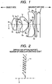
- Fig. 1 is a view showing an imaging lens according to an exemplary embodiment 1 of the present invention.
- AN imaging lens in the embodiment illustrated, is in a three-lens structure suitably applicable for a cellular phone camera.
- the imaging lens having a horizontal angle of view of 50 degrees or greater, is arranged with a first lens L 1 having a positive refractive power, a second lens L 2 having a positive or negative refractive power, and a third lens L 3 for aberration correction (whose refractive power may be positive or negative).
- a diffractive optical surface is provided in at least one of the first and second lenses L 1 , L 2 .
- the refractive optical surface is formed to have twenty or less orbicular gratings that are in a range to pass effective rays of light. Where to enhance the resolution, the total number of orbicular gratings is preferably provided 10 or less.
- a solid-state imaging device 1 such as of CCD or CMOS, is arranged in a position nearly corresponding to an imaging plane (a focal plane) of the imaging lens of this embodiment.
- the solid-state imaging device 1 is arranged with its cover glass (including various filters) 2 in a position closer to the object.
- an aperture stop 3 is arranged between the first lens L 1 and the second lens L 2 .
- the diffractive optical surface is provided in a surface, of the both surfaces of the lens (first lens L 1 ) arranged closest to the aperture stop 3, whose surface shape is smaller in overall change in a range to pass effective rays of light, i.e. surface smaller in positional change in an optical-axis direction (surface closer to the image).
- the orbicular gratings in the diffractive optical surface are recessed inward of the basic surface (basic surface of the lens prior to forming a diffractive optical surface) (brazed in a manner recessed inward of the basic surface)
- the conditional expression (1) is satisfied that is described in the section "Means for Solving the Problem" (described again in the following).
- the numeral in the right side of the conditional expression (1) is given as 0.00203 (mm).
- At least one of the first to third lenses L 1 - L 3 is preferably made aspherical al least in one surface thereof.
- Such a lens structure is significant, which is explained in the following.
- the first lens by providing the first lens with a positive refractive power, it can be made as so-called a telephoto type to reduce the overall length thereof.
- the telephoto type readily causes a chromatic aberration.
- the diffractive optical surface in at least one surface of the first and second lenses, it is possible to suitably correct for on-axis chromatic aberration.
- the orbicular gratings if increasing in the number in the diffractive optical surface, makes fabrication difficult, increases flare or reduces refractive efficiency.
- the total number of orbicular gratings down to 20 or less, it is possible to form a diffractive optical surface easily at low cost while keeping a suitable optical performance.
- the orbicular gratings inward of the basic surface of the lens, it is possible to move the focal point of a longer length of light than the reference wavelength, located axially closer to the image than the focal point of the reference wavelength of light, toward the object into a point closer to the focal point of the reference wavelength. This can relieve the on-axis chromatic aberration at the longer wavelength to be readily visually perceived more easily as compared at the shorter wavelength.
- the diffractive optical surface is provided in the surface closer to the image, on which side the surface shape wholly changes smaller in the range to pass effective rays of light, of the both surfaces of the first lens L 1 arranged closest to the aperture stop 3. This can reduce the variation in the incident angle of effective rays of light upon the diffractive optical surface, thus making the diffraction effect uniform in the diffractive optical surface regardless of the position relative to the optical axis.
- diffraction effect can be obtained favorably by providing a diffractive optical surface to the lens arranged closest to the aperture stop 3. Nevertheless, there are cases that a diffractive optical surface cannot be provided to the lens arranged closest or that sufficient diffraction effect cannot be obtained by merely providing a diffractive optical surface to the lens arranged closest. Otherwise, where diffractive power is excessively given to the lens arranged closest, an inflection point is caused in the phase-difference function regulating the diffractive optical surface, possibly increasing flare.
- the diffractive optical surface is provided in the object-side surface of the second lens L 2 .
- the imaging lens in embodiment 1 is structured as shown in Fig. 1 .
- the descriptions made in the embodiment is omitted to explain, in order to avoid duplications.
- Fig. 2 is a magnification view (orbicular grating depth is depicted by exaggerating the depth thereof in order for easy viewing, which is true for the following Figs. 4 , 6 and 8 ) of a diffractive optical surface according to embodiment 1.
- the imaging lens in embodiment 1 is arranged with a first lens L 1 having a positive refractive power, an aperture stop 3, a second lens L 2 having a positive refractive power, and a third lens L 3 for correcting for aberration, in the order closer to the object.
- the first, second and third lenses L 1 , L 2 , L 3 are each structured aspherical at both surfaces.
- the first lens L 1 arranged closest to the aperture stop 3, is provided with a diffractive optical surface on the side closer to the image.
- the diffractive optical surface is formed with totally eight orbicular gratings that arc in the range to pass effective rays of light, as shown in Fig. 2 .
- the orbicular gratings are recessed inward of the basic surface 4 of the first lens L 1 on a side closer to the image.
- the orbicular gratings in the diffractive optical surface are arranged to satisfy the conditional expression (1) provided that the orbicular grating has a dept E and the lens has a refractive index N d at d-line where the orbicular gratings are formed.
- a radius-of-curvature R of a lens surface in embodiment 1 for aspherical surface, a radius-of-curvature in a position nearby the optical axis X, unit: mm
- a lens surface-to-surface axial distance (lens center thickness and lens-to-lens air spacing) D (mm)
- a lens refractive index N d and Abbe's number at d-line (true for Tables 2 to 6).
- Table 5 shows a value corresponding to the conditional expression (1) according to embodiment 1. Incidentally, the orbicular gratings are given a depth of 1.08 ⁇ m (true for embodiments 2 to 4).
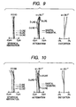
- Fig. 9 is an aberration diagram showing aberrations (spherical aberration, astigmatism and distortion) on the imaging lens according to embodiment 1.
- F represents an F-number and ⁇ a half angle of view, respectively.
- aberration is shown on the sagittal and tangential image surfaces (true for Figs. 10 to 12 ).
- the imaging lens in embodiment 1 is made short in overall length (5.92 mm) and can obtain a favorable optical performance despite that it is of the three-lens structure.
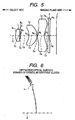
- Fig. 3 is a view showing a structure of an imaging lens according to example 1 while Fig. 4 is a magnification view of a diffractive optical surface according to example 1
- the imaging lens in example 1 is arranged with an aperture stop 3, a first lens L 1 having a positive refractive power, a second lens L 2 having a negative refractive power, and a third lens L 3 for correcting for aberration, in the order closer to the object.
- the first, second and third lenses L 1 , L 2 , L 3 are each structured aspherical at both surfaces.
- a diffractive optical surface is provided on the second lens L 2 , in a surface closer to the object. It has totally fifteen orbicular gratings that are in a range to pass effective rays of light, as shown in Fig. 4 . Meanwhile, the orbicular gratings in the diffractive optical surface are recessed inward of the object-side basic surface 4 of the second lens L 2 .
- the orbicular gratings are structured to satisfy the conditional expression (1) provided that the orbicular gratings have a depth E and the lens has a refractive index N d at d-line where the orbicular grating is formed.
- Table 5 shows a value corresponding to the conditional expression (1) according to example 1
- Fig. 10 is an aberration diagram showing aberrations (spherical aberration, astigmatism and distortion) on the imaging lens according to example 1
- the imaging lens in example 1 is made short in overall length (5.63 mm) and can obtain a favorable optical performance despite that it is of the three-lens structure.
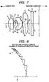
- Fig. 5 is a view showing a structure of an imaging lens according to example 2 while Fig. 6 is a magnification view of a diffractive optical surface according to example 2
- the imaging lens in example 2 is arranged with a first lens L 1 having a positive refractive power, an aperture stop 3, a second lens L 2 having a positive refractive power, and a third lens L 3 for correcting for aberration, in the order closer to the object.
- the first lens L 1 is structured spherical at both surfaces while the second and third lenses L 2 , L 3 are each structured aspherical at both surfaces.
- a diffractive optical surface is provided on the second lens L 2 , in a surface closer to the object. It has totally eleven orbicular gratings that are in a range to pass effective rays of light, as shown in Fig. 6 . Meanwhile, the orbicular gratings in the diffractive optical surface are recessed inward of the object-side basic surface 4 of the second lens L 2 .
- the orbicular gratings are structured to satisfy the conditional expression (1) provided that the orbicular gratings have a depth E and the lens has a refractive index N d at d-line where the orbicular grating is formed.
- Fig. 11 is an aberration diagram showing aberrations (spherical aberration, astigmatism and distortion) on the imaging lens according to embodiment 3.
- the imaging lens in embodiment 3 is made short in overall length (7.42 mm) and can obtain a favorable optical performance despite that it is of the three-lens structure.
- Fig. 7 is a view showing a structure of an imaging lens according to example 3 while Fig. 8 is a magnification view of a diffractive optical surface according to
- the imaging lens in example 3 is arranged with a first lens L 1 having a positive refractive power, an aperture stop 3, a second lens L 2 having a positive refractive power, and a third lens L 3 having a positive refractive power, in the order closer to the object.
- the first, second and third lenses L 1 , L 2 and L 3 are each structured aspherical at both surfaces.
- a diffractive optical surface is provided on the second lens L 2 , in a surface closer to the object. It has totally eight orbicular gratings that are in a range to pass effective rays of light, as shown in Fig. 8 . Meanwhile, the orbicular gratings in the diffractive optical surface are recessed inward of the object-side basic surface 4 of the second lens L 2 .
- the orbicular gratings are structured to satisfy the conditional expression (1) provided that the orbicular gratings have a depth E and the lens has a refractive index N d at d-linc where the orbicular grating is formed.
- Table 5 shows a value corresponding to the conditional expression (1) according to example 3.
- Fig. 12 is an aberration diagram showing aberrations (spherical aberration, astigmatism and distortion) on the imaging lens according to example 3.
- the imaging lens in example 3. is made short in overall length (6.48 mm) and can obtain a favorable optical performance despite that it is of the three-lens structure.
- Table 5 Embodiment 1 0.0021176 Example 1 0.0020337 Example 2 0.0020362 Example 3 0.0020317
- the imaging lens in the invention is not limited to the embodiment, and examples but can be modified to various forms.
- the diffractive optical surface in the example was provided for only one of the lens surfaces, a plurality of diffractive optical surface may be provided.
- the imaging lens in the invention can be mounted on a monitor camera having an imaging device such as of a CCD or a MOS or on various optical apparatuses such as vehicular cameras, besides on a camera for a cellular phone.
Abstract
Description
- The present invention relates to an imaging lens for use on a digital imaging device for a monitor camera, a vehicular camera or the like having a solid-state imaging device, such as of CCD or MOS, and more particularly to a light-weighted small-sized imaging lens to be suitably applied for a cellular phone camera.
- As the solid-state imaging device reduces in size and the number of pixels thereof increases, the imaging lenses for use on various digital imaging devices are required smaller in size and more favorable in optical performance obtainable. Particularly, for the imaging lenses to be mounted on the popular cellular phone, manufacture at lower cost is required in addition to that desire.
- There is a proposal on an imaging lens that optical performances are favorably obtained by the provision of a lens with a diffractive optical surface while keeping the two or three lens structure (see
JP-A-2004-191844 JP-A-10-90596 - However, it is difficult for the two-lens structure, described in
JP-A-2004-191844 JP-A-10-90596 - Meanwhile, the three-lens structure described in
JP-A-10-90596 US-A-2003/0223129 discloses an hybrid lensystems with at least are diffractive surface. - An object of an illustrative, non-limiting embodiment of the invention is to provide an imaging lens, which is short in overall length and capable of obtaining optical performances favorably even when the imaging lens is made in the three-lens structure.
- One aspect of the invention is an imaging lens as defined in
claim 1. - Additional embodiments are defined independent claims.
- The features of the invention will appear more fully upon consideration of the exemplary embodiment of the invention, which are schematically set forth in the drawings, in which:
-
Fig. 1 is a view showing a structure of an imaging lens according to the main embodiment of the invention; -
Fig. 2 is a magnification view of a diffractive optical surface according to the main embodiment ; -
Fig. 3 is a view showing a structure of an imaging lens according to example 1; -
Fig. 4 is a magnification view of a diffractive optical surface according to example 1; -
Fig. 5 is a view showing a structure of an imaging lens according to example 2 ; -
Fig. 6 is a magnification view of a diffractive optical surface according to example 2 ; -
Fig. 7 is a view showing a structure of an imaging lens according to example 3; -
Fig. 8 is a magnification view of a diffractive optical surface according to example 3 ; -
Fig. 9 is an aberration diagram showing aberrations (spherical aberration, astigmatism, distortion) on an imaging lens according to the main embodiment ; -
Fig. 10 is an aberration diagram showing aberrations (spherical aberration, astigmatism, distortion) on an imaging lens according to example 1 ; -
Fig. 11 is an aberration diagram showing aberrations (spherical aberration, astigmatism, distortion) on an imaging lens according to example 2 ; and -
Fig. 12 is an aberration diagram showing aberrations (spherical aberration, astigmatism, distortion) on an imaging lens according to example 3; - Although the invention will be described below with reference to the exemplary embodiments thereof, the following exemplary embodiments and modifications do not restrict the invention.
- According to the main embodiment, an imaging lens can be made as so-called a telephoto type by providing a first lens with a positive refractive power, thereby making it possible to reduce the overall length.
- Meanwhile, although there is a usual tendency to cause a chromatic aberration on a telephoto type, the imaging lens is allowed to suitably correct for on-axis chromatic aberration by providing a diffractive optical surface in at least one surface of the first and second lenses.
- Meanwhile, by providing, in the diffractive optical surface, twenty or less orbicular gratings that are in a range to pass effective rays of light, the diffractive optical surface is made easy to fabricate thereby suppressing the manufacture cost. In addition, the occurrence of flare can be suppressed by enhancing the diffraction efficient.
- With reference to the drawings, an embodiment in the present invention will now be explained in detail.
-
Fig. 1 is a view showing an imaging lens according to anexemplary embodiment 1 of the present invention. - AN imaging lens, in the embodiment illustrated, is in a three-lens structure suitably applicable for a cellular phone camera. The imaging lens, having a horizontal angle of view of 50 degrees or greater, is arranged with a first lens L1 having a positive refractive power, a second lens L2 having a positive or negative refractive power, and a third lens L3 for aberration correction (whose refractive power may be positive or negative).
- A diffractive optical surface is provided in at least one of the first and second lenses L1, L2. The refractive optical surface is formed to have twenty or less orbicular gratings that are in a range to pass effective rays of light. Where to enhance the resolution, the total number of orbicular gratings is preferably provided 10 or less.
- Meanwhile, a solid-
state imaging device 1, such as of CCD or CMOS, is arranged in a position nearly corresponding to an imaging plane (a focal plane) of the imaging lens of this embodiment. The solid-state imaging device 1 is arranged with its cover glass (including various filters) 2 in a position closer to the object. Furthermore, anaperture stop 3 is arranged between the first lens L1 and the second lens L2. - In the imaging lens of the embodiment, the diffractive optical surface is provided in a surface, of the both surfaces of the lens (first lens L1) arranged closest to the
aperture stop 3, whose surface shape is smaller in overall change in a range to pass effective rays of light, i.e. surface smaller in positional change in an optical-axis direction (surface closer to the image). The orbicular gratings in the diffractive optical surface are recessed inward of the basic surface (basic surface of the lens prior to forming a diffractive optical surface) (brazed in a manner recessed inward of the basic surface) - Preferably, provided that the orbicular gratings have a depth E and the lens has a refractive index Nd at d-line where the relevant orbicular grating is formed, the conditional expression (1) is satisfied that is described in the section "Means for Solving the Problem" (described again in the following).

- Incidentally, more preferably, the numeral in the right side of the conditional expression (1) is given as 0.00203 (mm).
- Meanwhile, at least one of the first to third lenses L1 - L3 is preferably made aspherical al least in one surface thereof.
- Such a lens structure is significant, which is explained in the following.
- Firstly, by providing the first lens with a positive refractive power, it can be made as so-called a telephoto type to reduce the overall length thereof.
- Usually, the telephoto type readily causes a chromatic aberration. However, by providing a diffractive optical surface in at least one surface of the first and second lenses, it is possible to suitably correct for on-axis chromatic aberration.
- Meanwhile, where the overall length is decreased, there is a usual tendency toward causing a curvature-of-field. However, by making the lens surface aspherical, such a curvature-of-field can be corrected suitably.
- Meanwhile, the orbicular gratings, if increasing in the number in the diffractive optical surface, makes fabrication difficult, increases flare or reduces refractive efficiency. However, by reducing the total number of orbicular gratings down to 20 or less, it is possible to form a diffractive optical surface easily at low cost while keeping a suitable optical performance.
- Meanwhile, by recessing the orbicular gratings inward of the basic surface of the lens, it is possible to move the focal point of a longer length of light than the reference wavelength, located axially closer to the image than the focal point of the reference wavelength of light, toward the object into a point closer to the focal point of the reference wavelength. This can relieve the on-axis chromatic aberration at the longer wavelength to be readily visually perceived more easily as compared at the shorter wavelength.
- Meanwhile, the diffractive optical surface is provided in the surface closer to the image, on which side the surface shape wholly changes smaller in the range to pass effective rays of light, of the both surfaces of the first lens L1 arranged closest to the
aperture stop 3. This can reduce the variation in the incident angle of effective rays of light upon the diffractive optical surface, thus making the diffraction effect uniform in the diffractive optical surface regardless of the position relative to the optical axis. - Incidentally, in usual cases, diffraction effect can be obtained favorably by providing a diffractive optical surface to the lens arranged closest to the
aperture stop 3. Nevertheless, there are cases that a diffractive optical surface cannot be provided to the lens arranged closest or that sufficient diffraction effect cannot be obtained by merely providing a diffractive optical surface to the lens arranged closest. Otherwise, where diffractive power is excessively given to the lens arranged closest, an inflection point is caused in the phase-difference function regulating the diffractive optical surface, possibly increasing flare. - In such a case, it is preferable to provide a diffractive optical surface to a lens other than the lens arranged closest to the
aperture stop 3. However, in case the ratio increases of the rays of light passing through steps (portions rising axially) in the diffractive optical surface relative to the whole portion of rays of light passing the diffractive optical surface, there incurs a lowering in light amount. Hence, the provision is preferably in a position as close as to theaperture stop 3. Accordingly, where the problem like the above arises, the diffractive optical surface is provided in the object-side surface of the second lens L2. - Meanwhile, by providing the orbicular grating with a depth E in a manner satisfying the conditional expression (1), -1-degree diffraction efficiency can be enhanced in the longer wavelength of visible portion of light (red region of light) wherein 0-degree diffraction effect can be reduced which is responsible for flare. This can relieve the bleeding of color.
- An imaging lens in the invention will be explained in detail by using concrete embodiments.
- The imaging lens in
embodiment 1 is structured as shown inFig. 1 . The descriptions made in the embodiment is omitted to explain, in order to avoid duplications. -
Fig. 2 is a magnification view (orbicular grating depth is depicted by exaggerating the depth thereof in order for easy viewing, which is true for the followingFigs. 4 ,6 and8 ) of a diffractive optical surface according toembodiment 1. - As shown in
Fig. 1 , the imaging lens inembodiment 1 is arranged with a first lens L1 having a positive refractive power, anaperture stop 3, a second lens L2 having a positive refractive power, and a third lens L3 for correcting for aberration, in the order closer to the object. The first, second and third lenses L1, L2, L3 are each structured aspherical at both surfaces. - The first lens L1, arranged closest to the
aperture stop 3, is provided with a diffractive optical surface on the side closer to the image. The diffractive optical surface is formed with totally eight orbicular gratings that arc in the range to pass effective rays of light, as shown inFig. 2 . The orbicular gratings are recessed inward of thebasic surface 4 of the first lens L1 on a side closer to the image. The orbicular gratings in the diffractive optical surface are arranged to satisfy the conditional expression (1) provided that the orbicular grating has a dept E and the lens has a refractive index Nd at d-line where the orbicular gratings are formed. - Concrete data is shown as to
embodiment 1, which is as follows. - In the upper part of Table 1, there are shown a radius-of-curvature R of a lens surface in embodiment 1 (for aspherical surface, a radius-of-curvature in a position nearby the optical axis X, unit: mm), a lens surface-to-surface axial distance (lens center thickness and lens-to-lens air spacing) D (mm), a lens refractive index Nd and Abbe's number at d-line (true for Tables 2 to 6).
- In the middle part of Table 1, there is shown an aspherical coefficient of an aspherical surface represented by the expression (A) given below (true for Table 2 to 4).
- In the lower part of Table 1, there is shown a coefficient in the diffractive-surface phase-difference function represented by the expression (B) given below (true for Table 2 to 4).


where - Z:
- length of a perpendicular drawn from a point on an aspherical surface, distant Y from the optical axis, to a tangential plane (plane vertical to the optical axis) for the aspherical-surface peak,
- Y:
- distance from the optical axis
- R:
- radius-of-curvature of the aspherical surface, in a position nearby the optical axis
- K:
- eccentricity
- Ai:
- aspherical coefficient (i = 3 - n)
- r:
- height relative to the optical axis
- C2j:
- coefficient (j = 1 - n) in a 2j-degree phase-difference function.
- Table 5 shows a value corresponding to the conditional expression (1) according to
embodiment 1. Incidentally, the orbicular gratings are given a depth of 1.08 µm (true forembodiments 2 to 4). - Meanwhile,
Fig. 9 is an aberration diagram showing aberrations (spherical aberration, astigmatism and distortion) on the imaging lens according toembodiment 1. In the aberration diagram, F represents an F-number and ω a half angle of view, respectively. Meanwhile, in the aberration diagrams related to astigmatism, aberration is shown on the sagittal and tangential image surfaces (true forFigs. 10 to 12 ). - As shown in Table 1 and
Fig. 9 , the imaging lens inembodiment 1 is made short in overall length (5.92 mm) and can obtain a favorable optical performance despite that it is of the three-lens structure. -
Fig. 3 is a view showing a structure of an imaging lens according to example 1 whileFig. 4 is a magnification view of a diffractive optical surface according to example 1 - As shown in
Fig. 3 , the imaging lens in example 1 is arranged with anaperture stop 3, a first lens L1 having a positive refractive power, a second lens L2 having a negative refractive power, and a third lens L3 for correcting for aberration, in the order closer to the object. The first, second and third lenses L1, L2, L3 are each structured aspherical at both surfaces. - A diffractive optical surface is provided on the second lens L2, in a surface closer to the object. It has totally fifteen orbicular gratings that are in a range to pass effective rays of light, as shown in
Fig. 4 . Meanwhile, the orbicular gratings in the diffractive optical surface are recessed inward of the object-sidebasic surface 4 of the second lens L2. The orbicular gratings are structured to satisfy the conditional expression (1) provided that the orbicular gratings have a depth E and the lens has a refractive index Nd at d-line where the orbicular grating is formed. - Concrete data is shown as to
embodiment 1, which is as follows.

- Table 5 shows a value corresponding to the conditional expression (1) according to example 1
- Meanwhile,
Fig. 10 is an aberration diagram showing aberrations (spherical aberration, astigmatism and distortion) on the imaging lens according to example 1 - As shown in Table 2 and
Fig. 10 , the imaging lens in example 1 is made short in overall length (5.63 mm) and can obtain a favorable optical performance despite that it is of the three-lens structure. -
Fig. 5 is a view showing a structure of an imaging lens according to example 2 whileFig. 6 is a magnification view of a diffractive optical surface according to example 2 - As shown in
Fig. 5 , the imaging lens in example 2 is arranged with a first lens L1 having a positive refractive power, anaperture stop 3, a second lens L2 having a positive refractive power, and a third lens L3 for correcting for aberration, in the order closer to the object. The first lens L1 is structured spherical at both surfaces while the second and third lenses L2, L3 are each structured aspherical at both surfaces. - A diffractive optical surface is provided on the second lens L2, in a surface closer to the object. It has totally eleven orbicular gratings that are in a range to pass effective rays of light, as shown in
Fig. 6 . Meanwhile, the orbicular gratings in the diffractive optical surface are recessed inward of the object-sidebasic surface 4 of the second lens L2. The orbicular gratings are structured to satisfy the conditional expression (1) provided that the orbicular gratings have a depth E and the lens has a refractive index Nd at d-line where the orbicular grating is formed. - Concrete data is shown as to example 2 which is as follows.

- Table 5 shows a value corresponding to the conditional expression (1) according to example 2 Meanwhile,
Fig. 11 is an aberration diagram showing aberrations (spherical aberration, astigmatism and distortion) on the imaging lens according toembodiment 3. - As shown in Table 3 and
Fig. 11 , the imaging lens inembodiment 3 is made short in overall length (7.42 mm) and can obtain a favorable optical performance despite that it is of the three-lens structure. -
Fig. 7 is a view showing a structure of an imaging lens according to example 3 whileFig. 8 is a magnification view of a diffractive optical surface according to - As shown in
Fig. 7 , the imaging lens in example 3 is arranged with a first lens L1 having a positive refractive power, anaperture stop 3, a second lens L2 having a positive refractive power, and a third lens L3 having a positive refractive power, in the order closer to the object. The first, second and third lenses L1, L2 and L3 are each structured aspherical at both surfaces. - A diffractive optical surface is provided on the second lens L2, in a surface closer to the object. It has totally eight orbicular gratings that are in a range to pass effective rays of light, as shown in
Fig. 8 . Meanwhile, the orbicular gratings in the diffractive optical surface are recessed inward of the object-sidebasic surface 4 of the second lens L2. The orbicular gratings are structured to satisfy the conditional expression (1) provided that the orbicular gratings have a depth E and the lens has a refractive index Nd at d-linc where the orbicular grating is formed. - Concrete data is shown as to example 3 which is as follows.

- Table 5 shows a value corresponding to the conditional expression (1) according to example 3.
- Meanwhile,
Fig. 12 is an aberration diagram showing aberrations (spherical aberration, astigmatism and distortion) on the imaging lens according to example 3. - As shown in Table 4 and
Fig. 12 , the imaging lens in example 3. is made short in overall length (6.48 mm) and can obtain a favorable optical performance despite that it is of the three-lens structure.Table 5 Embodiment 10.0021176 Example 1 0.0020337 Example 2 0.0020362 Example 3 0.0020317 - Incidentally, the imaging lens in the invention is not limited to the embodiment, and examples but can be modified to various forms. For example, although the diffractive optical surface in the example was provided for only one of the lens surfaces, a plurality of diffractive optical surface may be provided.
- Meanwhile, the imaging lens in the invention can be mounted on a monitor camera having an imaging device such as of a CCD or a MOS or on various optical apparatuses such as vehicular cameras, besides on a camera for a cellular phone.
- It will be apparent to those skilled in the art that various modifications and variations can be made to the described embodiment and example 3 of the invention without departing from the scope of the invention. Thus, it is intended that the invention cover all modifications and variations of this invention consistent with the scope of the appended claims and their equivalents.
where
Claims (3)
- An imaging lens consisting of order from an object side of the imaging lens,
a first lens having a positive refractive power;
a second lens having one of a positive refractive power and a negative refractive power; and a third lens that corrects for aberration,
further consisting of an aperture stop on an object side of the first lens or between the first and second lenses,
wherein at least one or the first and second lenses has a diffractive optical surface, the diffractive optical surface having twenty or less orbicular gratings in a range to pass an effective light ray, and wherein a lens arranged closest to the aperture stop has the diffractive optical surface on a surface having a form, which is in the range to pass the effective light ray, smaller in overall change than that of an opposite surface of the lens. - The imaging lens according to claim 1, which satisfies conditional expression (1):

wherein E represents a depth of the orbicular gratings, and Nd represents a refractive index at a d-line of a lens having the orbicular gratings. - The imaging lens according to any one of the preceeding claims, which is configured as a telephoto type imaging lens
Applications Claiming Priority (1)
| Application Number | Priority Date | Filing Date | Title |
|---|---|---|---|
| JP2005275981A JP2007086485A (en) | 2005-09-22 | 2005-09-22 | Imaging lens |
Publications (2)
| Publication Number | Publication Date |
|---|---|
| EP1767975A1 EP1767975A1 (en) | 2007-03-28 |
| EP1767975B1 true EP1767975B1 (en) | 2011-01-12 |
Family
ID=37459498
Family Applications (1)
| Application Number | Title | Priority Date | Filing Date |
|---|---|---|---|
| EP06019796A Not-in-force EP1767975B1 (en) | 2005-09-22 | 2006-09-21 | Imaging lens comprising at least a lens with a diffractive optical surface |
Country Status (8)
| Country | Link |
|---|---|
| US (1) | US7623307B2 (en) |
| EP (1) | EP1767975B1 (en) |
| JP (1) | JP2007086485A (en) |
| KR (1) | KR100812685B1 (en) |
| CN (1) | CN100476490C (en) |
| AT (1) | ATE495473T1 (en) |
| DE (1) | DE602006019531D1 (en) |
| TW (1) | TW200714917A (en) |
Cited By (1)
| Publication number | Priority date | Publication date | Assignee | Title |
|---|---|---|---|---|
| TWI557463B (en) * | 2014-12-03 | 2016-11-11 | 先進光電科技股份有限公司 | Optical image capturing system |
Families Citing this family (25)
| Publication number | Priority date | Publication date | Assignee | Title |
|---|---|---|---|---|
| JP2007127953A (en) * | 2005-11-07 | 2007-05-24 | Konica Minolta Opto Inc | Imaging optical system, imaging lens device and digital equipment |
| JP2007127960A (en) * | 2005-11-07 | 2007-05-24 | Konica Minolta Opto Inc | Imaging optical system, imaging lens device and digital equipment |
| DE102007044228A1 (en) * | 2007-08-17 | 2009-04-02 | Carl Zeiss Surgical Gmbh | Optical device |
| JP2009098505A (en) * | 2007-10-18 | 2009-05-07 | Sony Corp | Imaging lens and imaging device |
| JP5172490B2 (en) * | 2008-06-17 | 2013-03-27 | 富士フイルム株式会社 | Imaging lens and capsule endoscope |
| JP5097058B2 (en) * | 2008-09-03 | 2012-12-12 | パナソニック株式会社 | Imaging lens and imaging apparatus using the same |
| TWI412782B (en) * | 2009-03-27 | 2013-10-21 | Hon Hai Prec Ind Co Ltd | Imaging lens |
| JP5426313B2 (en) * | 2009-10-15 | 2014-02-26 | 日立マクセル株式会社 | Imaging lens system |
| JP2011112719A (en) * | 2009-11-24 | 2011-06-09 | Panasonic Corp | Image pickup lens and image pickup device using the same, and portable device equipped with the image pickup device |
| WO2011161971A1 (en) * | 2010-06-24 | 2011-12-29 | ナルックス株式会社 | Image pickup optical system |
| JP5601586B2 (en) | 2011-01-13 | 2014-10-08 | 株式会社ニコン | Optical system and optical equipment |
| TWI449946B (en) * | 2011-12-19 | 2014-08-21 | Largan Precision Co Ltd | Optical lens assembly for image taking |
| TWI443367B (en) * | 2012-03-09 | 2014-07-01 | Largan Precision Co Ltd | Image capturing lens system |
| JP6292711B2 (en) * | 2014-04-14 | 2018-03-14 | カンタツ株式会社 | Imaging lens |
| CN104503067B (en) * | 2014-09-22 | 2017-04-26 | 青岛歌尔声学科技有限公司 | Image capture lens |
| TWI546562B (en) * | 2014-12-04 | 2016-08-21 | 先進光電科技股份有限公司 | Optical image capturing system |
| US9274310B1 (en) * | 2014-12-23 | 2016-03-01 | Glory Science Co., Ltd. | Optical imaging lens |
| TWI572890B (en) * | 2015-01-29 | 2017-03-01 | 先進光電科技股份有限公司 | Optical image capturing system |
| US9946051B2 (en) * | 2015-04-22 | 2018-04-17 | Samsung Electronics Co., Ltd. | Imaging apparatus and image sensor including the same |
| TWI561850B (en) * | 2015-05-15 | 2016-12-11 | Ability Opto Electronics Technology Co Ltd | Optical image capturing system |
| TWI579585B (en) * | 2015-05-15 | 2017-04-21 | 先進光電科技股份有限公司 | Optical image capturing system |
| CN105093502A (en) * | 2015-09-01 | 2015-11-25 | 苏州凯锝微电子有限公司 | Refractive/diffractive hybrid type handset lens assembly |
| CN110531505B (en) * | 2019-10-29 | 2020-02-28 | 江西联创电子有限公司 | Infrared optical imaging lens and imaging device |
| CN111929817B (en) * | 2020-09-02 | 2021-03-26 | 诚瑞光学(苏州)有限公司 | Image pickup optical lens |
| CN112180603B (en) * | 2020-09-30 | 2023-05-19 | 维沃移动通信有限公司 | Projection device and intelligent glasses |
Family Cites Families (19)
| Publication number | Priority date | Publication date | Assignee | Title |
|---|---|---|---|---|
| US5543966A (en) * | 1993-12-29 | 1996-08-06 | Eastman Kodak Company | Hybrid refractive/diffractive achromatic camera lens |
| US5493441A (en) * | 1994-01-13 | 1996-02-20 | Texas Instruments Incorporated | Infrared continuous zoom telescope using diffractive optics |
| US5699142A (en) | 1994-09-01 | 1997-12-16 | Alcon Laboratories, Inc. | Diffractive multifocal ophthalmic lens |
| JPH1090596A (en) | 1996-09-13 | 1998-04-10 | Matsushita Electric Ind Co Ltd | Optical system with grating element and image pickup device formed by using the same |
| JPH10186223A (en) * | 1996-10-24 | 1998-07-14 | Asahi Optical Co Ltd | Triplet lens |
| US6101035A (en) * | 1996-10-24 | 2000-08-08 | Asahi Kogaku Kogyo Kabushiki Kaisha | Triplet lens system with diffractive lens features |
| US6839174B1 (en) * | 1997-03-03 | 2005-01-04 | Olympus Corporation | Relief type diffraction optical element, optical system comprising the same and mold for manufacturing the same |
| JPH10311946A (en) | 1997-05-12 | 1998-11-24 | Olympus Optical Co Ltd | Triplet lens |
| JP4004140B2 (en) | 1998-04-30 | 2007-11-07 | オリンパス株式会社 | Zoom lens using diffractive optical element and image pickup apparatus using the same |
| WO2000013048A1 (en) * | 1998-08-28 | 2000-03-09 | Ksm Associates, Inc. | Optical systems employing stepped diffractive surfaces |
| WO2002029797A1 (en) | 2000-10-03 | 2002-04-11 | Koninklijke Philips Electronics N.V. | Optical scanning device |
| JP2002281236A (en) * | 2001-03-22 | 2002-09-27 | Canon Inc | Image-reading apparatus |
| US6741403B2 (en) * | 2002-05-31 | 2004-05-25 | Largan Precision Co., Ltd. | Hybrid lens system |
| JP2004191844A (en) | 2002-12-13 | 2004-07-08 | Minolta Co Ltd | Imaging lens |
| JP4382423B2 (en) | 2003-09-09 | 2009-12-16 | フジノン株式会社 | Three-lens single focus lens |
| US7061695B2 (en) * | 2003-11-04 | 2006-06-13 | Eastman Kodak Company | Three element optical system |
| KR100577977B1 (en) * | 2004-03-12 | 2006-05-11 | (주)웨이텍 | Photographing lens system |
| JP2005301048A (en) | 2004-04-14 | 2005-10-27 | Sankyo Seiki Mfg Co Ltd | Fixed focus lens |
| CN100462770C (en) * | 2004-10-28 | 2009-02-18 | 清华大学 | Minisize camera lens system |
-
2005
- 2005-09-22 JP JP2005275981A patent/JP2007086485A/en active Pending
-
2006
- 2006-09-20 CN CNB2006101389510A patent/CN100476490C/en not_active Expired - Fee Related
- 2006-09-21 DE DE602006019531T patent/DE602006019531D1/en active Active
- 2006-09-21 AT AT06019796T patent/ATE495473T1/en not_active IP Right Cessation
- 2006-09-21 TW TW095134994A patent/TW200714917A/en not_active IP Right Cessation
- 2006-09-21 US US11/524,405 patent/US7623307B2/en not_active Expired - Fee Related
- 2006-09-21 EP EP06019796A patent/EP1767975B1/en not_active Not-in-force
- 2006-09-21 KR KR1020060091844A patent/KR100812685B1/en not_active IP Right Cessation
Cited By (2)
| Publication number | Priority date | Publication date | Assignee | Title |
|---|---|---|---|---|
| TWI557463B (en) * | 2014-12-03 | 2016-11-11 | 先進光電科技股份有限公司 | Optical image capturing system |
| US9729771B2 (en) | 2014-12-03 | 2017-08-08 | Ability Opto-Electronics Technology Co., Ltd. | Optical image capturing system |
Also Published As
| Publication number | Publication date |
|---|---|
| KR20070033923A (en) | 2007-03-27 |
| CN100476490C (en) | 2009-04-08 |
| US20070064316A1 (en) | 2007-03-22 |
| EP1767975A1 (en) | 2007-03-28 |
| JP2007086485A (en) | 2007-04-05 |
| ATE495473T1 (en) | 2011-01-15 |
| KR100812685B1 (en) | 2008-03-13 |
| TW200714917A (en) | 2007-04-16 |
| CN1936643A (en) | 2007-03-28 |
| DE602006019531D1 (en) | 2011-02-24 |
| TWI314653B (en) | 2009-09-11 |
| US7623307B2 (en) | 2009-11-24 |
Similar Documents
| Publication | Publication Date | Title |
|---|---|---|
| EP1767975B1 (en) | Imaging lens comprising at least a lens with a diffractive optical surface | |
| US7633690B2 (en) | Photographic lens | |
| KR100851838B1 (en) | Imaging lens | |
| US7453654B2 (en) | Imaging lens | |
| JP4963187B2 (en) | Imaging lens and imaging apparatus | |
| JP7034756B2 (en) | Imaging lens | |
| US9897777B2 (en) | Optical system | |
| JP5588858B2 (en) | Imaging lens | |
| US20160313538A1 (en) | Photographic Lens System Enabling Reduction in Tightness of Manufacturing Tolerance | |
| US7256946B2 (en) | Zoom lens having a wide angle of view and a high zooming ratio and a camera employing the same | |
| KR100799217B1 (en) | Photographic lens | |
| US8203797B2 (en) | Photographing optical lens assembly | |
| US11644653B2 (en) | Optical imaging lens assembly and electronic device | |
| KR101276534B1 (en) | Photographic lens optical system | |
| JP3753184B1 (en) | Imaging lens | |
| JP6587293B2 (en) | Imaging lens | |
| US7342730B2 (en) | Zoom lens optical system | |
| JP2008129349A (en) | Imaging lens and image pickup apparatus equipped with same | |
| JP5693352B2 (en) | Imaging lens | |
| JP4344229B2 (en) | Imaging lens | |
| JP2007264676A (en) | Wide angle lens | |
| EP3474057A1 (en) | Image-capturing optical system and image-capturing device | |
| JP2005202019A (en) | Imaging lens | |
| JP4877478B2 (en) | Zoom lens for image sensor | |
| JP2008139644A (en) | Optical system and optical equipment with same |
Legal Events
| Date | Code | Title | Description |
|---|---|---|---|
| PUAI | Public reference made under article 153(3) epc to a published international application that has entered the european phase |
Free format text: ORIGINAL CODE: 0009012 |
|
| 17P | Request for examination filed |
Effective date: 20060921 |
|
| AK | Designated contracting states |
Kind code of ref document: A1 Designated state(s): AT BE BG CH CY CZ DE DK EE ES FI FR GB GR HU IE IS IT LI LT LU LV MC NL PL PT RO SE SI SK TR |
|
| AX | Request for extension of the european patent |
Extension state: AL BA HR MK YU |
|
| AKX | Designation fees paid |
Designated state(s): AT BE BG CH CY CZ DE DK EE ES FI FR GB GR HU IE IS IT LI LT LU LV MC NL PL PT RO SE SI SK TR |
|
| 17Q | First examination report despatched |
Effective date: 20081205 |
|
| GRAP | Despatch of communication of intention to grant a patent |
Free format text: ORIGINAL CODE: EPIDOSNIGR1 |
|
| GRAS | Grant fee paid |
Free format text: ORIGINAL CODE: EPIDOSNIGR3 |
|
| GRAA | (expected) grant |
Free format text: ORIGINAL CODE: 0009210 |
|
| AK | Designated contracting states |
Kind code of ref document: B1 Designated state(s): AT BE BG CH CY CZ DE DK EE ES FI FR GB GR HU IE IS IT LI LT LU LV MC NL PL PT RO SE SI SK TR |
|
| REG | Reference to a national code |
Ref country code: GB Ref legal event code: FG4D |
|
| REG | Reference to a national code |
Ref country code: CH Ref legal event code: EP |
|
| REG | Reference to a national code |
Ref country code: IE Ref legal event code: FG4D |
|
| REF | Corresponds to: |
Ref document number: 602006019531 Country of ref document: DE Date of ref document: 20110224 Kind code of ref document: P |
|
| REG | Reference to a national code |
Ref country code: DE Ref legal event code: R096 Ref document number: 602006019531 Country of ref document: DE Effective date: 20110224 |
|
| REG | Reference to a national code |
Ref country code: NL Ref legal event code: VDEP Effective date: 20110112 |
|
| LTIE | Lt: invalidation of european patent or patent extension |
Effective date: 20110112 |
|
| PG25 | Lapsed in a contracting state [announced via postgrant information from national office to epo] |
Ref country code: GR Free format text: LAPSE BECAUSE OF FAILURE TO SUBMIT A TRANSLATION OF THE DESCRIPTION OR TO PAY THE FEE WITHIN THE PRESCRIBED TIME-LIMIT Effective date: 20110413 Ref country code: ES Free format text: LAPSE BECAUSE OF FAILURE TO SUBMIT A TRANSLATION OF THE DESCRIPTION OR TO PAY THE FEE WITHIN THE PRESCRIBED TIME-LIMIT Effective date: 20110423 Ref country code: IS Free format text: LAPSE BECAUSE OF FAILURE TO SUBMIT A TRANSLATION OF THE DESCRIPTION OR TO PAY THE FEE WITHIN THE PRESCRIBED TIME-LIMIT Effective date: 20110512 Ref country code: LT Free format text: LAPSE BECAUSE OF FAILURE TO SUBMIT A TRANSLATION OF THE DESCRIPTION OR TO PAY THE FEE WITHIN THE PRESCRIBED TIME-LIMIT Effective date: 20110112 Ref country code: SE Free format text: LAPSE BECAUSE OF FAILURE TO SUBMIT A TRANSLATION OF THE DESCRIPTION OR TO PAY THE FEE WITHIN THE PRESCRIBED TIME-LIMIT Effective date: 20110112 Ref country code: PT Free format text: LAPSE BECAUSE OF FAILURE TO SUBMIT A TRANSLATION OF THE DESCRIPTION OR TO PAY THE FEE WITHIN THE PRESCRIBED TIME-LIMIT Effective date: 20110512 Ref country code: LV Free format text: LAPSE BECAUSE OF FAILURE TO SUBMIT A TRANSLATION OF THE DESCRIPTION OR TO PAY THE FEE WITHIN THE PRESCRIBED TIME-LIMIT Effective date: 20110112 |
|
| PG25 | Lapsed in a contracting state [announced via postgrant information from national office to epo] |
Ref country code: NL Free format text: LAPSE BECAUSE OF FAILURE TO SUBMIT A TRANSLATION OF THE DESCRIPTION OR TO PAY THE FEE WITHIN THE PRESCRIBED TIME-LIMIT Effective date: 20110112 Ref country code: CY Free format text: LAPSE BECAUSE OF FAILURE TO SUBMIT A TRANSLATION OF THE DESCRIPTION OR TO PAY THE FEE WITHIN THE PRESCRIBED TIME-LIMIT Effective date: 20110112 Ref country code: BG Free format text: LAPSE BECAUSE OF FAILURE TO SUBMIT A TRANSLATION OF THE DESCRIPTION OR TO PAY THE FEE WITHIN THE PRESCRIBED TIME-LIMIT Effective date: 20110412 Ref country code: AT Free format text: LAPSE BECAUSE OF FAILURE TO SUBMIT A TRANSLATION OF THE DESCRIPTION OR TO PAY THE FEE WITHIN THE PRESCRIBED TIME-LIMIT Effective date: 20110112 Ref country code: BE Free format text: LAPSE BECAUSE OF FAILURE TO SUBMIT A TRANSLATION OF THE DESCRIPTION OR TO PAY THE FEE WITHIN THE PRESCRIBED TIME-LIMIT Effective date: 20110112 Ref country code: FI Free format text: LAPSE BECAUSE OF FAILURE TO SUBMIT A TRANSLATION OF THE DESCRIPTION OR TO PAY THE FEE WITHIN THE PRESCRIBED TIME-LIMIT Effective date: 20110112 Ref country code: PL Free format text: LAPSE BECAUSE OF FAILURE TO SUBMIT A TRANSLATION OF THE DESCRIPTION OR TO PAY THE FEE WITHIN THE PRESCRIBED TIME-LIMIT Effective date: 20110112 Ref country code: SI Free format text: LAPSE BECAUSE OF FAILURE TO SUBMIT A TRANSLATION OF THE DESCRIPTION OR TO PAY THE FEE WITHIN THE PRESCRIBED TIME-LIMIT Effective date: 20110112 |
|
| PG25 | Lapsed in a contracting state [announced via postgrant information from national office to epo] |
Ref country code: DK Free format text: LAPSE BECAUSE OF FAILURE TO SUBMIT A TRANSLATION OF THE DESCRIPTION OR TO PAY THE FEE WITHIN THE PRESCRIBED TIME-LIMIT Effective date: 20110112 Ref country code: EE Free format text: LAPSE BECAUSE OF FAILURE TO SUBMIT A TRANSLATION OF THE DESCRIPTION OR TO PAY THE FEE WITHIN THE PRESCRIBED TIME-LIMIT Effective date: 20110112 |
|
| PLBE | No opposition filed within time limit |
Free format text: ORIGINAL CODE: 0009261 |
|
| STAA | Information on the status of an ep patent application or granted ep patent |
Free format text: STATUS: NO OPPOSITION FILED WITHIN TIME LIMIT |
|
| PG25 | Lapsed in a contracting state [announced via postgrant information from national office to epo] |
Ref country code: RO Free format text: LAPSE BECAUSE OF FAILURE TO SUBMIT A TRANSLATION OF THE DESCRIPTION OR TO PAY THE FEE WITHIN THE PRESCRIBED TIME-LIMIT Effective date: 20110112 Ref country code: CZ Free format text: LAPSE BECAUSE OF FAILURE TO SUBMIT A TRANSLATION OF THE DESCRIPTION OR TO PAY THE FEE WITHIN THE PRESCRIBED TIME-LIMIT Effective date: 20110112 Ref country code: SK Free format text: LAPSE BECAUSE OF FAILURE TO SUBMIT A TRANSLATION OF THE DESCRIPTION OR TO PAY THE FEE WITHIN THE PRESCRIBED TIME-LIMIT Effective date: 20110112 |
|
| 26N | No opposition filed |
Effective date: 20111013 |
|
| PG25 | Lapsed in a contracting state [announced via postgrant information from national office to epo] |
Ref country code: IT Free format text: LAPSE BECAUSE OF FAILURE TO SUBMIT A TRANSLATION OF THE DESCRIPTION OR TO PAY THE FEE WITHIN THE PRESCRIBED TIME-LIMIT Effective date: 20110112 |
|
| REG | Reference to a national code |
Ref country code: DE Ref legal event code: R097 Ref document number: 602006019531 Country of ref document: DE Effective date: 20111013 |
|
| PG25 | Lapsed in a contracting state [announced via postgrant information from national office to epo] |
Ref country code: MC Free format text: LAPSE BECAUSE OF NON-PAYMENT OF DUE FEES Effective date: 20110930 |
|
| REG | Reference to a national code |
Ref country code: CH Ref legal event code: PL |
|
| REG | Reference to a national code |
Ref country code: IE Ref legal event code: MM4A |
|
| PG25 | Lapsed in a contracting state [announced via postgrant information from national office to epo] |
Ref country code: IE Free format text: LAPSE BECAUSE OF NON-PAYMENT OF DUE FEES Effective date: 20110921 Ref country code: LI Free format text: LAPSE BECAUSE OF NON-PAYMENT OF DUE FEES Effective date: 20110930 Ref country code: CH Free format text: LAPSE BECAUSE OF NON-PAYMENT OF DUE FEES Effective date: 20110930 |
|
| PGFP | Annual fee paid to national office [announced via postgrant information from national office to epo] |
Ref country code: GB Payment date: 20120919 Year of fee payment: 7 |
|
| PGFP | Annual fee paid to national office [announced via postgrant information from national office to epo] |
Ref country code: DE Payment date: 20120919 Year of fee payment: 7 Ref country code: FR Payment date: 20120926 Year of fee payment: 7 |
|
| PG25 | Lapsed in a contracting state [announced via postgrant information from national office to epo] |
Ref country code: LU Free format text: LAPSE BECAUSE OF NON-PAYMENT OF DUE FEES Effective date: 20110921 |
|
| PG25 | Lapsed in a contracting state [announced via postgrant information from national office to epo] |
Ref country code: TR Free format text: LAPSE BECAUSE OF FAILURE TO SUBMIT A TRANSLATION OF THE DESCRIPTION OR TO PAY THE FEE WITHIN THE PRESCRIBED TIME-LIMIT Effective date: 20110112 |
|
| PG25 | Lapsed in a contracting state [announced via postgrant information from national office to epo] |
Ref country code: HU Free format text: LAPSE BECAUSE OF FAILURE TO SUBMIT A TRANSLATION OF THE DESCRIPTION OR TO PAY THE FEE WITHIN THE PRESCRIBED TIME-LIMIT Effective date: 20110112 |
|
| GBPC | Gb: european patent ceased through non-payment of renewal fee |
Effective date: 20130921 |
|
| REG | Reference to a national code |
Ref country code: DE Ref legal event code: R119 Ref document number: 602006019531 Country of ref document: DE Effective date: 20140401 |
|
| REG | Reference to a national code |
Ref country code: FR Ref legal event code: ST Effective date: 20140530 |
|
| PG25 | Lapsed in a contracting state [announced via postgrant information from national office to epo] |
Ref country code: GB Free format text: LAPSE BECAUSE OF NON-PAYMENT OF DUE FEES Effective date: 20130921 |
|
| PG25 | Lapsed in a contracting state [announced via postgrant information from national office to epo] |
Ref country code: FR Free format text: LAPSE BECAUSE OF NON-PAYMENT OF DUE FEES Effective date: 20130930 Ref country code: DE Free format text: LAPSE BECAUSE OF NON-PAYMENT OF DUE FEES Effective date: 20140401 |