EP1767792A2 - Connecting device for two multilayer plates composed from a resin layer between two metal sheets - Google Patents
Connecting device for two multilayer plates composed from a resin layer between two metal sheets Download PDFInfo
- Publication number
- EP1767792A2 EP1767792A2 EP06120303A EP06120303A EP1767792A2 EP 1767792 A2 EP1767792 A2 EP 1767792A2 EP 06120303 A EP06120303 A EP 06120303A EP 06120303 A EP06120303 A EP 06120303A EP 1767792 A2 EP1767792 A2 EP 1767792A2
- Authority
- EP
- European Patent Office
- Prior art keywords
- plates
- plate
- cutout
- connecting device
- punching member
- Prior art date
- Legal status (The legal status is an assumption and is not a legal conclusion. Google has not performed a legal analysis and makes no representation as to the accuracy of the status listed.)
- Withdrawn
Links
- 229910052751 metal Inorganic materials 0.000 title claims abstract description 50
- 239000002184 metal Substances 0.000 title claims abstract description 50
- 239000011347 resin Substances 0.000 title abstract description 15
- 229920005989 resin Polymers 0.000 title abstract description 15
- 239000000463 material Substances 0.000 claims abstract description 38
- 238000004080 punching Methods 0.000 claims description 32
- 238000003466 welding Methods 0.000 claims description 25
- 238000000034 method Methods 0.000 claims description 24
- 210000002105 tongue Anatomy 0.000 claims description 20
- 229910000679 solder Inorganic materials 0.000 claims description 13
- 238000005520 cutting process Methods 0.000 claims description 9
- 238000005304 joining Methods 0.000 claims description 5
- 230000000295 complement effect Effects 0.000 claims description 3
- 238000003825 pressing Methods 0.000 claims description 3
- 239000012777 electrically insulating material Substances 0.000 claims description 2
- 210000000056 organ Anatomy 0.000 claims 1
- 238000010586 diagram Methods 0.000 description 18
- 238000005219 brazing Methods 0.000 description 7
- 239000002648 laminated material Substances 0.000 description 5
- 239000007787 solid Substances 0.000 description 4
- 230000001788 irregular Effects 0.000 description 3
- 238000002844 melting Methods 0.000 description 3
- 230000008018 melting Effects 0.000 description 3
- 239000011324 bead Substances 0.000 description 2
- 239000003990 capacitor Substances 0.000 description 2
- 230000006835 compression Effects 0.000 description 2
- 238000007906 compression Methods 0.000 description 2
- 239000000945 filler Substances 0.000 description 2
- 238000010438 heat treatment Methods 0.000 description 2
- 229910000831 Steel Inorganic materials 0.000 description 1
- AIAFIGZLFHZCAD-UHFFFAOYSA-N [Si].[Mn].[Cu] Chemical compound [Si].[Mn].[Cu] AIAFIGZLFHZCAD-UHFFFAOYSA-N 0.000 description 1
- KUNSUQLRTQLHQQ-UHFFFAOYSA-N copper tin Chemical compound [Cu].[Sn] KUNSUQLRTQLHQQ-UHFFFAOYSA-N 0.000 description 1
- 238000002788 crimping Methods 0.000 description 1
- 238000007872 degassing Methods 0.000 description 1
- 230000006866 deterioration Effects 0.000 description 1
- 230000004927 fusion Effects 0.000 description 1
- 238000012423 maintenance Methods 0.000 description 1
- 238000012544 monitoring process Methods 0.000 description 1
- 239000013307 optical fiber Substances 0.000 description 1
- 238000010992 reflux Methods 0.000 description 1
- 238000000926 separation method Methods 0.000 description 1
- 230000035939 shock Effects 0.000 description 1
- 238000004088 simulation Methods 0.000 description 1
- 238000005476 soldering Methods 0.000 description 1
- 239000010959 steel Substances 0.000 description 1
Images


Classifications
-
- F—MECHANICAL ENGINEERING; LIGHTING; HEATING; WEAPONS; BLASTING
- F16—ENGINEERING ELEMENTS AND UNITS; GENERAL MEASURES FOR PRODUCING AND MAINTAINING EFFECTIVE FUNCTIONING OF MACHINES OR INSTALLATIONS; THERMAL INSULATION IN GENERAL
- F16B—DEVICES FOR FASTENING OR SECURING CONSTRUCTIONAL ELEMENTS OR MACHINE PARTS TOGETHER, e.g. NAILS, BOLTS, CIRCLIPS, CLAMPS, CLIPS OR WEDGES; JOINTS OR JOINTING
- F16B5/00—Joining sheets or plates, e.g. panels, to one another or to strips or bars parallel to them
- F16B5/08—Joining sheets or plates, e.g. panels, to one another or to strips or bars parallel to them by means of welds or the like
-
- B—PERFORMING OPERATIONS; TRANSPORTING
- B21—MECHANICAL METAL-WORKING WITHOUT ESSENTIALLY REMOVING MATERIAL; PUNCHING METAL
- B21J—FORGING; HAMMERING; PRESSING METAL; RIVETING; FORGE FURNACES
- B21J15/00—Riveting
- B21J15/02—Riveting procedures
-
- B—PERFORMING OPERATIONS; TRANSPORTING
- B21—MECHANICAL METAL-WORKING WITHOUT ESSENTIALLY REMOVING MATERIAL; PUNCHING METAL
- B21J—FORGING; HAMMERING; PRESSING METAL; RIVETING; FORGE FURNACES
- B21J15/00—Riveting
- B21J15/02—Riveting procedures
- B21J15/025—Setting self-piercing rivets
-
- B—PERFORMING OPERATIONS; TRANSPORTING
- B21—MECHANICAL METAL-WORKING WITHOUT ESSENTIALLY REMOVING MATERIAL; PUNCHING METAL
- B21J—FORGING; HAMMERING; PRESSING METAL; RIVETING; FORGE FURNACES
- B21J15/00—Riveting
- B21J15/10—Riveting machines
- B21J15/14—Riveting machines specially adapted for riveting specific articles, e.g. brake lining machines
- B21J15/147—Composite articles
-
- F—MECHANICAL ENGINEERING; LIGHTING; HEATING; WEAPONS; BLASTING
- F16—ENGINEERING ELEMENTS AND UNITS; GENERAL MEASURES FOR PRODUCING AND MAINTAINING EFFECTIVE FUNCTIONING OF MACHINES OR INSTALLATIONS; THERMAL INSULATION IN GENERAL
- F16B—DEVICES FOR FASTENING OR SECURING CONSTRUCTIONAL ELEMENTS OR MACHINE PARTS TOGETHER, e.g. NAILS, BOLTS, CIRCLIPS, CLAMPS, CLIPS OR WEDGES; JOINTS OR JOINTING
- F16B5/00—Joining sheets or plates, e.g. panels, to one another or to strips or bars parallel to them
- F16B5/04—Joining sheets or plates, e.g. panels, to one another or to strips or bars parallel to them by means of riveting
- F16B5/045—Joining sheets or plates, e.g. panels, to one another or to strips or bars parallel to them by means of riveting without the use of separate rivets
-
- Y—GENERAL TAGGING OF NEW TECHNOLOGICAL DEVELOPMENTS; GENERAL TAGGING OF CROSS-SECTIONAL TECHNOLOGIES SPANNING OVER SEVERAL SECTIONS OF THE IPC; TECHNICAL SUBJECTS COVERED BY FORMER USPC CROSS-REFERENCE ART COLLECTIONS [XRACs] AND DIGESTS
- Y10—TECHNICAL SUBJECTS COVERED BY FORMER USPC
- Y10T—TECHNICAL SUBJECTS COVERED BY FORMER US CLASSIFICATION
- Y10T29/00—Metal working
- Y10T29/49—Method of mechanical manufacture
- Y10T29/49826—Assembling or joining
- Y10T29/49908—Joining by deforming
-
- Y—GENERAL TAGGING OF NEW TECHNOLOGICAL DEVELOPMENTS; GENERAL TAGGING OF CROSS-SECTIONAL TECHNOLOGIES SPANNING OVER SEVERAL SECTIONS OF THE IPC; TECHNICAL SUBJECTS COVERED BY FORMER USPC CROSS-REFERENCE ART COLLECTIONS [XRACs] AND DIGESTS
- Y10—TECHNICAL SUBJECTS COVERED BY FORMER USPC
- Y10T—TECHNICAL SUBJECTS COVERED BY FORMER US CLASSIFICATION
- Y10T29/00—Metal working
- Y10T29/51—Plural diverse manufacturing apparatus including means for metal shaping or assembling
- Y10T29/5178—Attachment
-
- Y—GENERAL TAGGING OF NEW TECHNOLOGICAL DEVELOPMENTS; GENERAL TAGGING OF CROSS-SECTIONAL TECHNOLOGIES SPANNING OVER SEVERAL SECTIONS OF THE IPC; TECHNICAL SUBJECTS COVERED BY FORMER USPC CROSS-REFERENCE ART COLLECTIONS [XRACs] AND DIGESTS
- Y10—TECHNICAL SUBJECTS COVERED BY FORMER USPC
- Y10T—TECHNICAL SUBJECTS COVERED BY FORMER US CLASSIFICATION
- Y10T29/00—Metal working
- Y10T29/51—Plural diverse manufacturing apparatus including means for metal shaping or assembling
- Y10T29/5191—Assembly
-
- Y—GENERAL TAGGING OF NEW TECHNOLOGICAL DEVELOPMENTS; GENERAL TAGGING OF CROSS-SECTIONAL TECHNOLOGIES SPANNING OVER SEVERAL SECTIONS OF THE IPC; TECHNICAL SUBJECTS COVERED BY FORMER USPC CROSS-REFERENCE ART COLLECTIONS [XRACs] AND DIGESTS
- Y10—TECHNICAL SUBJECTS COVERED BY FORMER USPC
- Y10T—TECHNICAL SUBJECTS COVERED BY FORMER US CLASSIFICATION
- Y10T29/00—Metal working
- Y10T29/53—Means to assemble or disassemble
- Y10T29/53996—Means to assemble or disassemble by deforming
Definitions
- the present invention is in the field of joining together two laminated plates. It relates to an assembly device between two plates, at least one of these plates being composed of at least one inner layer of resin interposed between two metal outer plates, the other plate comprising at least one metal sheet, if necessary external.
- a laminated plate material is known composed of several superimposed layers, including at least one inner layer of resin interposed between two external metal sheets.
- Such a material is in particular used in the automotive field, because of the mechanical characteristics offered with regard to the constraints related to this field, in particular as regards the lightness and the mechanical and thermal resistance.
- the assembly carried out must give the product obtained qualities of mechanical strengths sought, especially in the automotive field, including resistance to vibration and shock in case of accident.
- the assembly methods used should not affect the intrinsic qualities of the material, nor induce deformation thereof, both surface and in its general plan.
- the assembly methods used must avoid being a source of pollution of the product obtained.
- the assembly must be effective and durable, despite a simulation of the product obtained in vibratory environment. It is also sought assembling modalities whose industrialization is easy to implement, in particular according to precise methods, flexible and adaptable to any product to obtain, easily reproducible, limiting the work of preparing the plates and avoiding a warm-up of the inner layer of resin.
- Joining devices are known between two plates of laminated materials referred to above, using techniques of welding the plates together. Welding processes, such as spot welding or arc welding, are unsuitable due to the presence of the inner layer of resin which opposes the passage of electric current for heating the metal sheets. In the case where the method used allows electrical contact between the metal sheets, the heating causes the melting of the resin and a degassing of the latter which disrupts the welding operation and which alters the material.
- AUSUISSE AUSUISSE
- US4482600 KAWASAKI
- the object of the present invention is to propose an assembly device between two plates, at least one of these plates being composed of at least one inner layer of resin interposed between two metal outer plates, the other plate comprising at least one less a metal sheet, if necessary external, or even consisting of a monolithic metal sheet. It is more particularly proposed such a device that meets the constraints and difficulties that have been exposed.
- the device of the present invention is an assembly device between at least two plates. At least one of these plates is composed of at least one inner layer interposed between two metal outer plates.
- the inner layer is preferably made from an electrically insulating material, such as a resin or the like.
- the other plate comprises at least one metal sheet, or even a single outer metal sheet. This other plate may also consist of a monolithic metal sheet.
- such an assembly device is mainly recognizable in that at least one of the plates comprises a cutout for the passage of fixing means jointly engaged on a sheet of one of the plates and on a sheet metal. from the other plate.
- the fixing means consist of a punching member forming the cutout and comprising at its respective ends a bearing head on the outer sheet of one of the plates and at least one flap against the sheet metal. outside the other plate after crossing the plates.
- the punching member is for example constituted by a piercing end peg, the flap being formed by a crushing of said end.
- the punching member is hollowed out.
- the flap is in this case formed by an outward crushing of the piercing end.
- the recess of the punching member advantageously constitutes a chamber for receiving the material of the cut plates and compressed towards the inside of the recess of the punching member.
- the recess of the punching member is likely to open through the bearing head, and advantageously to form a chute for ejection of the cut material of the plates.
- the punching member consists of a clip comprising at least two perforating tabs whose ends are folded to form a flap, indifferently to the outside and / or inside.
- a method of implementing an assembly device as previously proposed consists in keeping the plates in relative position of superposition, in positioning the punching member and in applying against the head of pressing a thrust to cause a piercing through the plates by the punch member and form the cut, and then crush by means of a first tool the piercing end of the punch member to form the flap.
- the first tool comprises a relief of compression of the cut material of the plates against the inner face of the head.
- a second tool is equipped with a passage rod of the corridor for the ejection of the cut material of the plates.
- the fixing means consist of at least one plate placed in superposition against an outer metal sheet of a first plate.
- This plate comprises at least one connecting member at least partially passing through the blank to any one of the metal sheets of a second plate, for its attachment to the latter.
- the connecting member is for example constituted of a tongue resulting from the plate by cutting. This tongue is folded through the cutout to the outer metal sheet of the second plate, and comprises a fold of bearing against the outer face of the outer metal sheet of this plate.
- a plate may be placed in superposition against each of the plates, the folding of the tongue of any one of the plates being in this case pressed against the outer face of the other plate.
- the connecting member is constituted by a relief that includes the plate, and in particular from the latter. This relief extends partially through the cutout to the inner sheet of the second plate.
- the fixing means consist of a weld joint between the inner plate of the second plate and the bottom of the relief.
- the fixing means consist of cooperating members bearing against the outer metal sheet of a respective plate. At least one of these members at least partially through the cut for its connection with the other member.
- the cooperating members in particular steel, are preferably fixed to each other by welding.
- the cooperating members each consist of a shouldered body, the shoulders bearing against the outer face of the corresponding outer metal sheet.
- the bodies are housed at least partially inside the cut and are welded to one another.
- the cooperating members are likely to be generally shaped flanged bowl, and to be welded to each other through their bottom.
- a method of implementing an assembly device as previously proposed consists in arranging the cutouts beforehand and forming the cooperating members from platens placed against a respective plate. These plates are stamped by welding electrodes, for their setting into flanged bowl conformation and their welding to one another.
- the body of at least one of the members may have a conical bearing surface bearing the other body.
- This surface is in particular an intermediate surface for welding the bodies to one another.
- a first body has a first conical surface
- a second body has a second complementary conical surface, which is formed by crushing an edge of the second body through the first conical surface.
- a method of implementing an assembly device as previously proposed is to arrange the cutouts beforehand, and to place the cooperating members on either side of the plates by arranging the bodies. at least partially inside the cutout, then to exert a thrust and against axial thrust against the cooperating members by means of electrodes to cause the support of the cooperating members against the corresponding outer plate and the crushing of said stop , as well as their welding to each other.
- the cooperating members consist of a set of plates superimposed against an outer metal sheet of a plate respectively.
- These plates each comprise at least one tongue coming from the plates by cutting and folded through the blank to a tab of the other plate.
- These tongues comprise a return support against the return of the other tongue, through which returns the tongues are welded to one another.
- a method of implementing an assembly device as previously proposed consists in pre-cutting the cutouts, placing the plates against the corresponding plate, then stamping the plates by means of electrodes for deforming the tongues and welding them together.
- the cooperating members are constituted for one of a punching member of the plates and for the other of a receiving member of the emergent end out of the plates of the punching member.
- Such a punching member is likely to consist of a pin head and piercing tip, the receiving member consisting of a flush cup.
- the piercing tip and the bowl preferably have cone-bearing bearing surfaces, through which the pin and the bowl are welded to each other.
- the punching member is capable of being axially hollowed out. This recess constitutes a corridor for ejection of the cut material of the plates.
- At least one of the plates comprises the cutout formed therethrough.
- the fixing means are constituted by a weld seam bordering the periphery of the cut, by connecting one to the other the inner metal sheets superimposed plates.
- the cutout is formed of a lumen formed through the plate.
- the cutout is formed at the edge of one of the plates.
- the conformation of the edge of the cut is preferably of irregular shape, such as sinusoidal or the like in particular.
- the edge of the cutout preferably comprises a return formed by deformation of the corresponding plate, in particular made during the cutting operation.
- a first of the plates comprises at least one cutout formed in its wafer to form at least one interlocking relief inside a cutout formed through a second plate.
- the fastening means consist of at least one solder joint formed on the edge of a portion of the relief that emerges from the cutout formed through the second plate.
- a laminate material is composed of an inner layer of resin (1) interposed between two metal outer sheets (2,3).
- This material is packaged in a plate, two plates (4,5) being capable of being assembled to one another to form a product, in particular used in the automotive field.
- the plates (4,5) being superimposed as in the diagram shown, these plates (4,5) comprise an outer sheet (2) and an inner sheet (3), the inner sheets (3) of the superposed plates (4,5) being juxtaposed.
- such an assembly can be made between such a material and a monolithic metal sheet, or between such a material and another laminated material having at least one outer layer formed of a metal sheet.
- At least one of the plates (4,5) comprises a cutout for the passage of fastening means engaged on a metal sheet (2,3) of one and the other of the plates ( 4,5), this metal sheet being able to be an inner metal sheet (3) or an outer metal sheet (2).
- the punching member (7) consists of a pin (10) with head (8) and piercing tip (9).
- the head (8) of the pin (10) bears against the outer plate (2) of one of the plates (4), while its tip (9) bears against the outer plate (2) the other plate (5), after matting to form a flap (9 ').
- this pin (10) is forcefully introduced through the plates (4, 5) so as to perforate them and emerge at its end provided with the tip (9).
- an anvil (11) is placed against the head (8) of the pin (10), while a hammer (12) deforms its tip (9) to fold it by crushing against the corresponding plate (2).
- the punching member (7) consists of a clip (13) having a pair of perforating tabs whose ends are folded to form flaps (13 ').
- the legs are likely to be in number greater than two, and can be indifferently folded inwards or outwards as illustrated.
- the punching member (7) consists of a pin (14) axially recessed.
- This pin (14) has a head (15) bearing against the outer sheet (2) of a first plate (4), its other end being crushed by a tool (16) to form a flap (14 ') against the outer plate (2) of the second plate (5).
- a guide (17) is placed against the second plate (5), to prevent deformation of the plates (4,5) during the punching step.
- the cut material is compressed inside the recess of the pin (14), which constitutes a chamber (18) for receiving this material, and prevents the latter from being a source pollution.
- the tool (16) is not only a flap member of the end of the pin (14), but also a compression member of the cut material inside the receiving chamber (18).
- the inner recess of the pin (14) is closed by the head (15).
- the tool (16) flap end of the pin (14) comprises a relief (19) for compressing the cut material of the plates (4,5) against the inner face of the head (15) of the pawn (14).
- the internal recess of the pin (14) opens out through the head (15).
- the outlet of the recess of the pin (14) allows the centering of the latter by means of a tool (20).
- This tool (20) comprises a centering drum intended to be housed inside the recess of the pin (14).
- the recess emerging from the pin (14) is used to form a passage (21) for the passage of a rod (22) equipping a tool (23) for ejecting the material carved plates (4,5).
- the ejection tool (23) is integral with the flap tool (16), or forms with the latter (16) a one-piece tool.
- the fixing means comprise cooperating members.
- One of these members is constituted by a pin (24) with a punching head (25), the other member being constituted by a flanged bowl (26) for receiving the perforating end (27) of the pawn (24).
- a striking tool (28) pushes the pin (24) through the plates (4,5).
- An anvil (29) is disposed against the corresponding plate (5) to prevent deformation of the plates (4,5).
- the anvil (29) has a recess (29 '), preferably circular, to allow the passage of a material reflux from the plates (4,5) during the establishment of the pin (24).
- the rim cup (26) is attached by being held by a first electrode (30).
- a second electrode (31) is placed against the head (25) of the pin (24) to weld the pin (24) and the bowl (26) together.
- This welding operation can be performed by capacitor discharge for example.
- the piercing end (27) and the bowl (26) have conical bearing bearing surfaces, through which they are welded to each other.
- the pin (24) is full.
- the pin (24) is axially hollowed out, the recess possibly constituting a passage (21) for the passage of a rod (22) of a tool.
- the plates (4, 5) are assembled together by means of a plate (32) superposed on a first plate (4).
- the plate (32) comprises tabs (33) formed by cutting and folding.
- the tabs (33) are likely to be aligned, or to be arranged in staggered rows for a more balanced maintenance of the plates (4,5) between them.
- Cutouts (34) are provided beforehand through the plates (4, 5) for passage through the tabs (33) to the outer sheet (2) of the second plate (5).
- a single plate (32) is placed against one of the plates (4), while according to the embodiments shown in Fig.24 to Figs. 29, the plates (4,5) are provided with a respective plate (32), the tongues (33) are folded from one to the other of the plates (4,5).
- the tabs (33) comprise a fold (35) of bearing against the outer face of the outer plate (2) of the second plate (5).
- this support is made through the plate (32) which is provided with the second plate (5).
- the plates (32) are placed in superposition against an outer sheet (2) of a respective plate (4,5).
- the tongues (33) of a plate (32) are deformed towards the tongues (33) of the other plate (32), by means of electrodes not shown in the figures.
- the tongues (33) are not only deformed to bear against each other via a return (33 '), but also are welded together under pressure.
- a cutout (36) is formed through a first plate (4), and a plate (37) is superimposed against this plate (4).
- An electrode (38) deforms the plate (37) to form a relief (39) which extends through the cutout (36) to the inner plate (3) of the second plate (5).
- the relief (39) is attached to the inner plate (3) of the second plate (5) via a solder joint (40).
- the relief (39) is formed by stamping prior to the establishment of the plate (37) against the first plate (4).
- a cutout (41) is formed through the two plates (4,5).
- a respective plate (42) is placed against the outer plate (2) of each of the plates (4,5).
- Two electrodes (43) deform a respective plate (42) to form reliefs shaped flanged bowl (44).
- These cups (44) extend through the cutout (41) until they are brought into contact in the middle zone of the latter.
- the reliefs (44) are welded to each other by their bottom by means of a weld joint (45).
- the plates may be replaced by a set of washers (46) shaped as a flanged bowl (44), or curved washers of the Belleville type, for example, whose flanges (47) respectively bear against each other.
- These washers (46) are fixed to each other by their bottom by means of a weld joint (48), by means of electrodes not shown.
- the washers (46) are planar and are deformed by tools and / or electrodes, similar to the electrodes (43) illustrated in FIG. 32, until their bottoms are brought into contact.
- a cutout (41) is previously formed through the plates (4,5). These are fixed to each other by means of cooperating members respectively assigned to each of the plates (4,5).
- One of these members is formed of a first stepped solid body (49), the other member being formed of a second shouldered body (50), which is axially recessed.
- the bodies (49,50) bear against the outer plate (2) of the plate (4,5) to which they are assigned via their shoulder (51), and extend partially through the cutout ( 41) until they come into contact with each other.
- the solid body (49) has a first conical bearing surface (52).
- the hollow body (50) and the solid body (49) are successively introduced inside the cutout (41), then the solid body (49) is pressed against the hollow body (50) via its surface.
- conical bearing (52) until crushing of the inner edge (53) of the corresponding end of the recessed body (50), forming thereon a second conical bearing surface cooperating with the first. This crushing is in particular carried out by means of electrodes assigned to each of the bodies (49,50), to fix them to each other by pressure welding, by capacitor discharge for example.
- the pressure associated with the flow of current causes a local melting of the material of the elements in contact with one another, which creates a solder joint.
- the pressure zones between the elements and the outer plates of the plates against which they respectively support, promote a robust assembly of the plates together.
- This method of assembly is quick to implement and causes a low thermal clearance, preserving the plates and in particular the inner layers of resin.
- no pollution is generated.
- the cutout (54) is formed through a first plate (4).
- This cutout (54) is on the illustrated embodiment of oblong shape, but could have any conformation.
- a solder joint (55), in particular made by adding material, is formed at the edge of the cutout (54) by being engaged on the inner sheets (3) superimposed plates (4,5).
- the weld joint (55) is obtained from the fusion of the inner sheets (3) of each of the plates (4,5), without adding material.
- the material supply is in particular carried out by soldering or brazing LASER, which makes it possible to obtain a fixing of the plates (4,5) between them without deterioration of the inner layer of resin (1), thanks to the precise focusing of the LASER beam on the areas to be welded, and in particular on the slices of the inner plates (3) of the plates (4,5).
- the LASER beam is a YAG beam, which is in particular conveyed by optical fiber.
- the welding head is preferably installed on an arm with automatic operation equipped with a system for detecting and monitoring the welding joint (55) practiced.
- the filler material is a metal, preferably copper-silicon-manganese type or copper-tin type for example, to allow a low temperature melting of the filler material.
- the cutouts (54) are likely to be formed through the first plate (4) in a regular or irregular manner, being aligned or arranged in staggered rows. According to an alternative embodiment, the cutouts (54) may be alternately formed in one and the other of the plates (4,5). Their position is also likely to be relatively arbitrary, without precise tolerances, by fixing the plates (4,5) together by welding an edge of the blank (54) formed in only one of the plates (4). In addition, no pollution is induced.
- the cutout (56) is formed in one of the plates (4,5), at the edge thereof.
- a solder joint (57) made by adding material is provided along the edge of the blank (56).
- This solder joint (57) is in particular a weld bead made by brazing or brazing, in particular by brazing LASER in the manner of the variant embodiment described in FIGS. 37 and 39.
- the cutout (56) is likely to have a rectilinear trajectory, without inflection. However, it is preferred to give this cutout (56) an irregular shape, such as sinusoidal in the illustrated embodiment.
- the respective edges of the plates (4,5) are offset relative to each other, the separation distance between these edges being capable of being indifferently constant or variable. Such a conformation of the cutout (56) allows a good peel strength of the plates (4,5) assembled.
- the cutout (56) formed in the plate (4) has a return (56 ') towards the outside of the plate (5).
- These arrangements are such that the contact surface between the solder joint (57) and the inner plate (3) of the plate (4) is optimized to improve the grip of the solder joint (57) on the plate (4) and finally to promote a stability of the welding.
- the two inner (3) and outer (2) plates of the plate (4) are curved, as illustrated in FIG. 41, or only the inner plate (3) of the plate (FIG. 4) has an inflection.
- the plates (4,5) are joined together orthogonally in their general plane.
- One of the plates (4) has first cutouts (58) formed in its edge, to form interlocking reliefs (59).
- the other plate (5) comprises second cutouts (60) of shape complementary to the conformation of the reliefs (59), for the purpose of interlocking the plates (4,5) between them.
- a solder joint (61) is provided, in particular by brazing or brazing LASER, at the edge of an emerging portion of the reliefs (59) out of the second cutouts (60) formed through the corresponding plate (5). This weld bead (61) is engaged on the outer plates (2) of the plates (4,5).
- each plate (4, 5) is capable of comprising one or more layers of material interposed between the metal sheets (2, 3), such as at least one other metal sheet, at least one other internal layer of resin, at least one other material.
Abstract
Description
La présente invention est du domaine de l'assemblage l'une à l'autre de deux plaques stratifiées. Elle a pour objet un dispositif d'assemblage entre deux plaques, l'une au moins de ces plaques étant composée d'au moins une couche interne de résine interposée entre deux tôles externes métalliques, l'autre plaque comprenant au moins une tôle métallique, le cas échéant externe.The present invention is in the field of joining together two laminated plates. It relates to an assembly device between two plates, at least one of these plates being composed of at least one inner layer of resin interposed between two metal outer plates, the other plate comprising at least one metal sheet, if necessary external.
On connaît un matériau en plaque stratifié composé de plusieurs couches superposées, dont au moins une couche interne de résine interposée entre deux tôles externes métalliques. Un tel matériau est notamment utilisé dans le domaine automobile, en raison des caractéristiques mécaniques offertes au regard des contraintes liées à ce domaine, notamment en ce qui concerne la légèreté et la résistance mécanique et thermique.A laminated plate material is known composed of several superimposed layers, including at least one inner layer of resin interposed between two external metal sheets. Such a material is in particular used in the automotive field, because of the mechanical characteristics offered with regard to the constraints related to this field, in particular as regards the lightness and the mechanical and thermal resistance.
Se pose le problème de l'assemblage entre un tel matériau en plaque et un autre matériau similaire, voire un autre matériau comportant au moins une tôle métallique, le cas échéant externe, voire une tôle métallique monolithique. Plus particulièrement, l'assemblage réalisé doit conférer au produit obtenu des qualités de résistances mécaniques recherchées, notamment dans le domaine automobile, et notamment une résistance aux vibrations et aux chocs en cas d'accident. En outre, les modalités d'assemblage mises en oeuvre ne doivent pas porter atteinte aux qualités intrinsèques du matériau, ni n'induire de déformation de celui-ci, tant de surface que dans son plan général. Enfin, les modalités d'assemblage mises en oeuvre doivent éviter d'être une source de pollution du produit obtenu.There is the problem of the connection between such a plate material and another similar material, or even another material comprising at least one metal sheet, possibly external, or even a monolithic metal sheet. More particularly, the assembly carried out must give the product obtained qualities of mechanical strengths sought, especially in the automotive field, including resistance to vibration and shock in case of accident. In addition, the assembly methods used should not affect the intrinsic qualities of the material, nor induce deformation thereof, both surface and in its general plan. Finally, the assembly methods used must avoid being a source of pollution of the product obtained.
Par ailleurs, l'assemblage doit être efficace et pérenne, malgré une mise en situation du produit obtenu en milieu vibratoire. Il est aussi recherché des modalités d'assemblage dont l'industrialisation soit aisée à mettre en oeuvre, notamment selon des procédés précis, flexibles et adaptable à un quelconque produit à obtenir, facilement reproductibles, limitant les travaux de préparation des plaques et évitant un échauffement de la couche interne de résine.Moreover, the assembly must be effective and durable, despite a simulation of the product obtained in vibratory environment. It is also sought assembling modalities whose industrialization is easy to implement, in particular according to precise methods, flexible and adaptable to any product to obtain, easily reproducible, limiting the work of preparing the plates and avoiding a warm-up of the inner layer of resin.
Il est connu des dispositifs d'assemblage entre deux plaques de matériaux stratifiés susvisés, mettant en oeuvre des techniques de soudage des plaques entre elles. Les procédés de soudage, tels que soudage par point ou soudage à l'arc, ne sont pas adaptés, en raison de la présence de la couche interne de résine qui s'oppose au passage du courant électrique destiné à chauffer les tôles métalliques. Dans le cas où le procédé utilisé permet un contact électrique entre les tôles métalliques, l'échauffement provoque la fusion de la résine et un dégazage de cette dernière qui perturbe l'opération de soudage et qui altère le matériau. On pourra par exemple se reporter aux documents
Il est aussi connu des dispositifs d'assemblage entre deux plaques de matériaux stratifiés susvisés, mettant en oeuvre des techniques de rivetage ou de vissage. Plus particulièrement, des avant-trous sont ménagés à travers l'une des plaques et l'une des tôles externes de l'autre plaque, pour l'introduction d'un rivet. Ce rivet est soumis à contrainte pour se déformer en expansion à l'intérieur de la couche interne de résine. On pourra par exemple se reporter au document
Le but de la présente invention est de proposer un dispositif d'assemblage entre deux plaques, l'une au moins de ces plaques étant composée d'au moins une couche interne de résine interposée entre deux tôles externes métalliques, l'autre plaque comprenant au moins une tôle métallique, le cas échéant externe, voire étant constituée d'une tôle métallique monolithique. Il est plus particulièrement proposé un tel dispositif qui réponde aux contraintes et difficultés qui ont été exposées.The object of the present invention is to propose an assembly device between two plates, at least one of these plates being composed of at least one inner layer of resin interposed between two metal outer plates, the other plate comprising at least one less a metal sheet, if necessary external, or even consisting of a monolithic metal sheet. It is more particularly proposed such a device that meets the constraints and difficulties that have been exposed.
Le dispositif de la présente invention est un dispositif d'assemblage entre au moins deux plaques. L'une au moins de ces plaques est composée d'au moins une couche interne interposée entre deux tôles externes métalliques. La couche interne est préférentiellement réalisée à partir d'un matériau électriquement isolant, telle qu'une résine ou analogue. L'autre plaque comprend au moins une tôle métallique, voire une tôle métallique unique extérieure. Cette autre plaque peut aussi être constituée d'une tôle métallique monolithique.The device of the present invention is an assembly device between at least two plates. At least one of these plates is composed of at least one inner layer interposed between two metal outer plates. The inner layer is preferably made from an electrically insulating material, such as a resin or the like. The other plate comprises at least one metal sheet, or even a single outer metal sheet. This other plate may also consist of a monolithic metal sheet.
Selon la présente invention, un tel dispositif d'assemblage est principalement reconnaissable en ce que l'une au moins des plaques comporte une découpe pour le passage de moyens de fixation conjointement en prise sur une tôle de l'une des plaques et sur une tôle de l'autre plaque.According to the present invention, such an assembly device is mainly recognizable in that at least one of the plates comprises a cutout for the passage of fixing means jointly engaged on a sheet of one of the plates and on a sheet metal. from the other plate.
Selon une forme de réalisation, les moyens de fixation sont constitués d'un organe de poinçonnage formant la découpe et comportant à ses extrémités respectives une tête d'appui sur la tôle extérieure de l'une des plaques et au moins un rabat contre la tôle extérieure de l'autre plaque après traversée des plaques.According to one embodiment, the fixing means consist of a punching member forming the cutout and comprising at its respective ends a bearing head on the outer sheet of one of the plates and at least one flap against the sheet metal. outside the other plate after crossing the plates.
L'organe de poinçonnage est par exemple constitué d'un pion à extrémité perforante, le rabat étant formé par un écrasement de ladite extrémité.The punching member is for example constituted by a piercing end peg, the flap being formed by a crushing of said end.
Par exemple encore, l'organe de poinçonnage est évidé. Le rabat est dans ce cas formé par un écrasement vers l'extérieur de l'extrémité perforante.For example again, the punching member is hollowed out. The flap is in this case formed by an outward crushing of the piercing end.
L'évidement de l'organe de poinçonnage constitue avantageusement une chambre de réception de la matière des plaques découpée et comprimée vers l'intérieur de l'évidement de l'organe de poinçonnage.The recess of the punching member advantageously constitutes a chamber for receiving the material of the cut plates and compressed towards the inside of the recess of the punching member.
L'évidement de l'organe de poinçonnage est susceptible d'être débouchant à travers la tête d'appui, et de constituer avantageusement un couloir d'éjection de la matière découpée des plaques.The recess of the punching member is likely to open through the bearing head, and advantageously to form a chute for ejection of the cut material of the plates.
Par exemple encore, l'organe de poinçonnage est constitué d'une agrafe comportant au moins deux pattes perforantes dont les extrémités sont repliées pour former un rabat, indifféremment vers l'extérieur et/ou l'intérieur.For example still, the punching member consists of a clip comprising at least two perforating tabs whose ends are folded to form a flap, indifferently to the outside and / or inside.
Toujours selon la présente invention, un procédé de mise en oeuvre d'un dispositif d'assemblage tel que précédemment proposé, consiste à maintenir les plaques en position relative de superposition, à positionner l'organe de poinçonnage et à appliquer contre la tête d'appui une poussée pour provoquer une traversée perforante des plaques par l'organe de poinçonnage et former la découpe, puis à écraser au moyen d'un premier outil l'extrémité perforante de l'organe de poinçonnage pour former le rabat.Still according to the present invention, a method of implementing an assembly device as previously proposed, consists in keeping the plates in relative position of superposition, in positioning the punching member and in applying against the head of pressing a thrust to cause a piercing through the plates by the punch member and form the cut, and then crush by means of a first tool the piercing end of the punch member to form the flap.
Le cas échéant, le premier outil comporte un relief de mise en compression de la matière découpée des plaques contre la face interne de la tête.If necessary, the first tool comprises a relief of compression of the cut material of the plates against the inner face of the head.
Le cas échéant encore, un deuxième outil est équipé d'une tige de traversée du couloir pour l'éjection de la matière découpée des plaques.If necessary, a second tool is equipped with a passage rod of the corridor for the ejection of the cut material of the plates.
Selon une autre forme de réalisation, les moyens de fixation sont constitués d'au moins une platine placée en superposition contre une tôle métallique extérieure d'une première plaque. Cette platine comporte au moins un organe de liaison traversant au moins partiellement la découpe vers l'une quelconque des tôles métalliques d'une deuxième plaque, pour sa fixation à cette dernière.According to another embodiment, the fixing means consist of at least one plate placed in superposition against an outer metal sheet of a first plate. This plate comprises at least one connecting member at least partially passing through the blank to any one of the metal sheets of a second plate, for its attachment to the latter.
L'organe de liaison est par exemple constitué d'une languette issue de la platine par découpage. Cette languette est rabattue à travers la découpe vers la tôle métallique extérieure de la deuxième plaque, et comporte un repli de prise d'appui contre la face extérieure de la tôle métallique extérieure de cette plaque.The connecting member is for example constituted of a tongue resulting from the plate by cutting. This tongue is folded through the cutout to the outer metal sheet of the second plate, and comprises a fold of bearing against the outer face of the outer metal sheet of this plate.
Une platine est susceptible d'être placée en superposition contre chacune des plaques, le repli de la languette de l'une quelconque des platines étant dans ce cas plaquée contre la face extérieure de l'autre platine.A plate may be placed in superposition against each of the plates, the folding of the tongue of any one of the plates being in this case pressed against the outer face of the other plate.
Par exemple encore, l'organe de liaison est constitué d'un relief que comporte la platine, et notamment issu de cette dernière. Ce relief s'étend partiellement à travers la découpe vers la tôle intérieure de la deuxième plaque. Les moyens de fixation sont constitués par un joint de soudure entre la tôle intérieure de la deuxième plaque et le fond du relief.For example still, the connecting member is constituted by a relief that includes the plate, and in particular from the latter. This relief extends partially through the cutout to the inner sheet of the second plate. The fixing means consist of a weld joint between the inner plate of the second plate and the bottom of the relief.
Selon une autre forme de réalisation, les moyens de fixation sont constitués d'organes coopérants en appui contre la tôle métallique extérieure d'une plaque respective. L'un au moins de ces organes traverse au moins partiellement la découpe pour sa mise en relation avec l'autre organe.According to another embodiment, the fixing means consist of cooperating members bearing against the outer metal sheet of a respective plate. At least one of these members at least partially through the cut for its connection with the other member.
Les organes coopérants, en acier notamment, sont préférentiellement fixés l'un à l'autre par soudage.The cooperating members, in particular steel, are preferably fixed to each other by welding.
Par exemple, les organes coopérants sont chacun constitués d'un corps épaulé, les épaulements prenant appui contre la face extérieure de la tôle métallique extérieure correspondante. Les corps sont logés au moins partiellement à l'intérieur de la découpe et sont soudés l'un à l'autre.For example, the cooperating members each consist of a shouldered body, the shoulders bearing against the outer face of the corresponding outer metal sheet. The bodies are housed at least partially inside the cut and are welded to one another.
Plus particulièrement, les organes coopérants sont susceptibles d'être globalement conformés en cuvette à rebord, et d'être soudés l'un à l'autre par l'intermédiaire de leur fond.More particularly, the cooperating members are likely to be generally shaped flanged bowl, and to be welded to each other through their bottom.
Toujours selon la présente l'invention, un procédé de mise en oeuvre d'un dispositif d'assemblage tel que précédemment proposé consiste à ménager préalablement les découpes et à former les organes coopérants à partir de platines placées contre une plaque respective. Ces platines sont embouties par des électrodes de soudage, pour leur mise en conformation en cuvette à rebord et leur soudage l'une à l'autre.Still according to the present invention, a method of implementing an assembly device as previously proposed consists in arranging the cutouts beforehand and forming the cooperating members from platens placed against a respective plate. These plates are stamped by welding electrodes, for their setting into flanged bowl conformation and their welding to one another.
Plus particulièrement encore, le corps de l'un au moins des organes est susceptible de comporter une surface à portée conique d'appui de l'autre corps. Cette surface est notamment une surface intermédiaire de soudage des corps l'un à l'autre.More particularly still, the body of at least one of the members may have a conical bearing surface bearing the other body. This surface is in particular an intermediate surface for welding the bodies to one another.
De préférence, un premier corps comporte une première surface à portée conique, tandis qu'un deuxième corps comporte une deuxième surface à portée conique complémentaire, qui est formée par écrasement d'une arête du deuxième corps par l'intermédiaire de la première surface conique.Preferably, a first body has a first conical surface, while a second body has a second complementary conical surface, which is formed by crushing an edge of the second body through the first conical surface. .
Toujours selon la présente l'invention, un procédé de mise en oeuvre d'un dispositif d'assemblage tel que précédemment proposé consiste à ménager préalablement les découpes, et à placer les organes coopérants de part et d'autre des plaques en disposant les corps au moins partiellement à l'intérieur de la découpe, puis à exercer une poussée et contre poussée axiale contre les organes coopérants au moyen d'électrodes pour provoquer la mise en appui des organes coopérants contre la tôle extérieure correspondante et l'écrasement de ladite arrête, ainsi que leur soudage l'un à l'autre.Still according to the present invention, a method of implementing an assembly device as previously proposed is to arrange the cutouts beforehand, and to place the cooperating members on either side of the plates by arranging the bodies. at least partially inside the cutout, then to exert a thrust and against axial thrust against the cooperating members by means of electrodes to cause the support of the cooperating members against the corresponding outer plate and the crushing of said stop , as well as their welding to each other.
Par exemple encore, les organes coopérants sont constitués d'un jeu de platines placées en superposition contre une tôle métallique extérieure d'une plaque respective. Ces platines comportent chacune au moins une languette issue des platines par découpage et rabattue à travers la découpe vers une languette de l'autre platine. Ces languettes comportent un retour d'appui contre le retour de l'autre languette, par l'intermédiaire desquels retours les languettes sont soudées l'une à l'autre.For example again, the cooperating members consist of a set of plates superimposed against an outer metal sheet of a plate respectively. These plates each comprise at least one tongue coming from the plates by cutting and folded through the blank to a tab of the other plate. These tongues comprise a return support against the return of the other tongue, through which returns the tongues are welded to one another.
Toujours selon la présente l'invention, un procédé de mise en oeuvre d'un dispositif d'assemblage tel que précédemment proposé, consiste à ménager préalablement les découpes, à placer les platines contre la plaque correspondante, puis à emboutir les platines au moyen d'électrodes pour déformer les languettes et les souder l'une à l'autre.Still according to the present invention, a method of implementing an assembly device as previously proposed, consists in pre-cutting the cutouts, placing the plates against the corresponding plate, then stamping the plates by means of electrodes for deforming the tongues and welding them together.
Par exemple encore, les organes coopérants sont constitués pour l'un d'un organe de poinçonnage des plaques et pour l'autre d'un organe de réception de l'extrémité émergeante hors des plaques de l'organe de poinçonnage.For example again, the cooperating members are constituted for one of a punching member of the plates and for the other of a receiving member of the emergent end out of the plates of the punching member.
Un tel organe de poinçonnage est susceptible d'être constitué d'un pion à tête et à pointe perforante, l'organe de réception étant constitué d'une cuvette à rebord.Such a punching member is likely to consist of a pin head and piercing tip, the receiving member consisting of a flush cup.
La pointe perforante et la cuvette comportent de préférence des surfaces d'appui à portée conique, par l'intermédiaire desquelles le pion et la cuvette sont soudés l'un à l'autre.The piercing tip and the bowl preferably have cone-bearing bearing surfaces, through which the pin and the bowl are welded to each other.
L'organe de poinçonnage est susceptible d'être axialement évidé. Cet évidement constitue un couloir d'éjection de la matière découpée des plaques.The punching member is capable of being axially hollowed out. This recess constitutes a corridor for ejection of the cut material of the plates.
Selon une autre forme de réalisation, l'une quelconque au moins des plaques comporte la découpe ménagée à son travers. Les moyens de fixation sont constitués par un joint de soudure bordant la périphérie de la découpe, en reliant l'une à l'autre les tôles métalliques intérieures superposées des plaques.According to another embodiment, at least one of the plates comprises the cutout formed therethrough. The fixing means are constituted by a weld seam bordering the periphery of the cut, by connecting one to the other the inner metal sheets superimposed plates.
Par exemple, la découpe est formée d'une lumière ménagée à travers la plaque.For example, the cutout is formed of a lumen formed through the plate.
Par exemple encore, la découpe est ménagée en bordure de l'une des plaques.For example again, the cutout is formed at the edge of one of the plates.
La conformation du bord de la découpe est préférentiellement de forme irrégulière, telle que sinusoïdale ou analogue notamment. Le bord de la découpe comporte de préférence un retour ménagé par déformation de la plaque correspondante, notamment réalisée lors de l'opération de découpe.The conformation of the edge of the cut is preferably of irregular shape, such as sinusoidal or the like in particular. The edge of the cutout preferably comprises a return formed by deformation of the corresponding plate, in particular made during the cutting operation.
Selon une autre forme de réalisation, une première des plaques comporte au moins une découpe ménagée dans sa tranche pour former au moins un relief d'emboîtement à l'intérieur d'une découpe ménagée à travers une deuxième plaque. Les moyens de fixation sont constitués d'au moins un joint de soudure réalisé en bordure d'une partie du relief qui émerge hors de la découpe ménagée à travers la deuxième plaque. Ces dispositions sont plus particulièrement destinées à l'assemblage de plaques transversalement l'une par rapport à l'autre, orthogonalement notamment. Les joints de soudure sont éventuellement ménagés le long de chacun des débouchés de la découpe.According to another embodiment, a first of the plates comprises at least one cutout formed in its wafer to form at least one interlocking relief inside a cutout formed through a second plate. The fastening means consist of at least one solder joint formed on the edge of a portion of the relief that emerges from the cutout formed through the second plate. These arrangements are more particularly intended for the assembly of plates transversely relative to each other, orthogonally in particular. The solder joints are optionally formed along each of the outlets of the cut.
La présente invention sera mieux comprise, et des détails en relevant apparaîtront, à la lecture de la description qui va en être faite en relation avec les figures des planches annexées, dans lesquelles :
- La fig.1 est un schéma illustrant un exemple de réalisation d'un couple de plaques en matériau stratifié, destinées à être assemblées entre elles au moyen d'un dispositif d'assemblage de l'invention.
- Les fig.2 à fig.4 sont des schémas illustrant un premier mode d'assemblage entre deux plaques au moyen d'un dispositif de l'invention.
- Les fig.5 à fig.7 sont des schémas illustrant un deuxième mode d'assemblage entre deux plaques au moyen d'un dispositif de l'invention.
- Les fig.8 et fig.9 sont des schémas illustrant un troisième mode d'assemblage entre deux plaques au moyen d'un dispositif de l'invention.
- Les fig.10 à fig.12 sont des schémas illustrant un quatrième mode d'assemblage entre deux plaques au moyen d'un dispositif de l'invention.
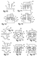
- La fig.13 est un schéma illustrant une variante des modalités d'assemblage représentées sur les fig.10 à fig.12.
- Les fig.14 à fig.19 sont des schémas illustrant deux variantes d'un cinquième mode d'assemblage entre deux plaques au moyen d'un dispositif de l'invention
- Les fig.20 à fig.25 sont des schémas illustrant deux variantes d'un sixième mode d'assemblage entre deux plaques au moyen d'un dispositif de l'invention.
- Les fig.26 à fig.29 sont des schémas illustrant un septième mode d'assemblage entre deux plaques au moyen d'un dispositif de l'invention.
- Les fig.30 et fig.31 sont des schémas illustrant un huitième mode d'assemblage entre deux plaques au moyen d'un dispositif de l'invention.
- Les fig.32 à fig.34 sont des schémas illustrant un neuvième mode d'assemblage entre deux plaques au moyen d'un dispositif de l'invention.
- Les fig.35 et fig.36 sont des schémas illustrant un dixième mode d'assemblage entre deux plaques au moyen d'un dispositif de l'invention.
- Les fig.37 et fig.38 sont des schémas illustrant un onzième mode d'assemblage entre deux plaques au moyen d'un dispositif de l'invention.
- Les fig.39 et fig.40 sont des schémas illustrant un douzième mode d'assemblage entre deux plaques au moyen d'un dispositif de l'invention.
- La fig.41 est un schéma illustrant un treizième mode d'assemblage entre deux plaques au moyen d'un dispositif de l'invention.
- Les fig.42 à fig.43 sont des schémas illustrant un quatorzième mode d'assemblage entre deux plaques au moyen d'un dispositif de l'invention.
- La fig.44 est un schéma illustrant un quinzième mode d'assemblage entre deux plaques au moyen d'un dispositif de l'invention.
- Fig.1 is a diagram illustrating an embodiment of a pair of plates of laminated material, intended to be assembled together by means of an assembly device of the invention.
- FIGS. 2 to 4 are diagrams illustrating a first mode of assembly between two plates by means of a device of the invention.
- Fig.5 to Fig.7 are diagrams illustrating a second mode of assembly between two plates by means of a device of the invention.
- Fig.8 and Fig.9 are diagrams illustrating a third mode of assembly between two plates by means of a device of the invention.
- Fig.10 to Fig.12 are diagrams illustrating a fourth mode of assembly between two plates by means of a device of the invention.
- Fig.13 is a diagram illustrating a variant of the assembly methods shown in Fig.10 to Fig.12.
- Fig.14 to Fig.19 are diagrams illustrating two variants of a fifth mode of assembly between two plates by means of a device of the invention
- Fig.20 to Fig.25 are diagrams illustrating two variants of a sixth mode of assembly between two plates by means of a device of the invention.
- Fig.26 to Fig.29 are diagrams illustrating a seventh mode of assembly between two plates by means of a device of the invention.
- Fig.30 and Fig.31 are diagrams illustrating an eighth mode of assembly between two plates by means of a device of the invention.
- Fig.32 to Fig.34 are diagrams illustrating a ninth mode of assembly between two plates by means of a device of the invention.
- The fig.35 and fig.36 are diagrams illustrating a tenth mode of assembly between two plates by means of a device of the invention.
- Fig.37 and Fig.38 are diagrams illustrating an eleventh mode of assembly between two plates by means of a device of the invention.
- Fig.39 and Fig.40 are diagrams illustrating a twelfth mode of assembly between two plates by means of a device of the invention.
- Fig.41 is a diagram illustrating a thirteenth mode of assembly between two plates by means of a device of the invention.
- Fig.42 to Fig.43 are diagrams illustrating a fourteenth mode of assembly between two plates by means of a device of the invention.
- Fig.44 is a diagram illustrating a fifteenth mode of assembly between two plates by means of a device of the invention.
Sur la fig.1, un matériau stratifié est composé d'une couche interne en résine (1), interposée entre deux tôles externes métalliques (2,3). Ce matériau est conditionné en plaque, deux plaques (4,5) étant susceptibles d'être assemblées l'une à l'autre pour former un produit, notamment utilisé dans le domaine automobile. Les plaques (4,5) étant superposées tel que sur le schéma représenté, ces plaques (4,5) comportent une tôle extérieure (2) et une tôle intérieure (3), les tôles intérieures (3) des plaques superposées (4,5) étant juxtaposées. De manière analogue, un tel assemblage est susceptible d'être réalisé entre un tel matériau et une tôle métallique monolithique, ou encore entre un tel matériau et un autre matériau stratifié comportant au moins une couche extérieure formée d'une tôle métallique.In Fig.1, a laminate material is composed of an inner layer of resin (1) interposed between two metal outer sheets (2,3). This material is packaged in a plate, two plates (4,5) being capable of being assembled to one another to form a product, in particular used in the automotive field. The plates (4,5) being superimposed as in the diagram shown, these plates (4,5) comprise an outer sheet (2) and an inner sheet (3), the inner sheets (3) of the superposed plates (4,5) being juxtaposed. Similarly, such an assembly can be made between such a material and a monolithic metal sheet, or between such a material and another laminated material having at least one outer layer formed of a metal sheet.
Selon l'invention proposée, au moins l'une des plaques (4,5) comporte une découpe pour le passage de moyens de fixation en prise sur une tôle métallique (2,3) de l'une et l'autre des plaques (4,5), cette tôle métallique pouvant être une tôle métallique intérieure (3) ou une tôle métallique extérieure (2).According to the proposed invention, at least one of the plates (4,5) comprises a cutout for the passage of fastening means engaged on a metal sheet (2,3) of one and the other of the plates ( 4,5), this metal sheet being able to be an inner metal sheet (3) or an outer metal sheet (2).
Sur les fig.2 à fig.19, il est proposé de ménager la découpe (6) directement lors de la mise en place des moyens de fixation. Un organe de poinçonnage (7) est utilisé non seulement pour pratiquer la découpe (6) à travers l'une et l'autre des plaques (4,5), mais aussi est exploité pour les assembler entre elles, lors d'une même opération de montage. Un tel mode d'assemblage permet de se dispenser d'une opération de découpage des plaques (4,5) préalablement à la mise en place des moyens de fixation des plaques (4,5) entre elles. En outre, l'industrialisation de ce mode d'assemblage est aisée, les découpes (6) ménagées à travers les plaques (4,5) étant pratiquées simultanément, avec pour avantage d'éviter d'avoir à les positionner rigoureusement l'une par rapport à l'autre dans le cas contraire, pour permettre la mise en place des moyens de fixation.In Fig.2 to Fig.19, it is proposed to spare the cutout (6) directly during the establishment of the fastening means. A punching member (7) is used not only for cutting (6) through one and the other of the plates (4,5), but also is used to assemble them together, at the same time. assembly operation. Such an assembly method makes it possible to dispense with a cutting operation of the plates (4, 5) prior to setting up the means for fastening the plates (4, 5) to one another. In addition, the industrialization of this method of assembly is easy, the cuts (6) formed through the plates (4,5) being practiced simultaneously, with the advantage of avoiding having to position rigorously one of them. relative to the other in the opposite case, to allow the establishment of fastening means.
Sur les fig.2 à fig.4, l'organe de poinçonnage (7) est constitué d'un pion (10) à tête (8) et à pointe perforante (9). Sur la fig.4, la tête (8) du pion (10) est en appui contre la tôle extérieure (2) de l'une des plaques (4), tandis que sa pointe (9) est en appui contre la tôle extérieure (2) de l'autre plaque (5), après matage pour former un rabat (9'). Sur la fig.2, ce pion (10) est introduit en force à travers les plaques (4,5) de manière à les perforer et à émerger à son extrémité munie de la pointe (9). Sur la fig.3, une enclume (11) est placée contre la tête (8) du pion (10), tandis qu'un marteau (12) déforme sa pointe (9) jusqu'à la rabattre par écrasement contre la tôle correspondante (2).In fig.2 to fig.4, the punching member (7) consists of a pin (10) with head (8) and piercing tip (9). In FIG. 4, the head (8) of the pin (10) bears against the outer plate (2) of one of the plates (4), while its tip (9) bears against the outer plate (2) the other plate (5), after matting to form a flap (9 '). In FIG. 2, this pin (10) is forcefully introduced through the plates (4, 5) so as to perforate them and emerge at its end provided with the tip (9). In Fig.3, an anvil (11) is placed against the head (8) of the pin (10), while a hammer (12) deforms its tip (9) to fold it by crushing against the corresponding plate (2).
Sur les fig.5 à fig.7, l'organe de poinçonnage (7) est constitué d'une agrafe (13) comportant un couple de pattes perforantes dont les extrémités sont repliées pour former des rabats (13'). Les pattes sont susceptibles d'être en nombre supérieur à deux, et peuvent être indifféremment rabattues vers l'intérieur ou vers l'extérieur tel qu'illustré.In fig.5 to fig.7, the punching member (7) consists of a clip (13) having a pair of perforating tabs whose ends are folded to form flaps (13 '). The legs are likely to be in number greater than two, and can be indifferently folded inwards or outwards as illustrated.
Sur les fig.8 à fig.13, l'organe de poinçonnage (7) est constitué d'un pion (14) axialement évidé. Ce pion (14) comporte une tête (15) d'appui contre la tôle extérieure (2) d'une première plaque (4), son autre extrémité étant écrasée par un outil (16) pour former un rabat (14') contre la tôle extérieure (2) de la deuxième plaque (5). Sur les fig.8 et fig.11, un guide (17) est placé contre la deuxième plaque (5), pour empêcher la déformation des plaques (4,5) lors de l'étape de poinçonnage. Sur les fig.9 et fig.12, la matière découpée est comprimée à l'intérieur de l'évidement du pion (14), qui constitue une chambre (18) de réception de cette matière, et évite que cette dernière ne soit source d'une pollution. L'outil (16) constitue non seulement un organe de rabat de l'extrémité du pion (14), mais aussi un organe de compression de la matière découpée à l'intérieur de la chambre de réception (18). Sur la variante illustrée sur les fig.8 et fig.9, l'évidement interne du pion (14) est obturé par la tête (15). L'outil (16) de rabat de l'extrémité du pion (14) comporte un relief (19) de mise en compression de la matière découpée des plaques (4,5), contre la face interne de la tête (15) du pion (14). Sur la variante illustrée sur les fig.10 à fig.13, l'évidement interne du pion (14) est débouchant à travers la tête (15). Sur la fig.11, le débouché de l'évidement du pion (14) permet le centrage de ce dernier au moyen d'un outil (20). Cet outil (20) comporte un fût de centrage destiné à être logé à l'intérieur de l'évidement du pion (14). Selon des modalités particulières représentées sur la fig.13, l'évidement débouchant du pion (14) est exploité pour former un couloir (21) de passage d'une tige (22) équipant un outil (23) d'éjection de la matière découpée des plaques (4,5). Selon une variante de réalisation, l'outil d'éjection (23) est solidaire de l'outil de rabat (16), voire forme avec ce dernier (16) un outil monobloc.In fig.8 to fig.13, the punching member (7) consists of a pin (14) axially recessed. This pin (14) has a head (15) bearing against the outer sheet (2) of a first plate (4), its other end being crushed by a tool (16) to form a flap (14 ') against the outer plate (2) of the second plate (5). In Fig.8 and Fig.11, a guide (17) is placed against the second plate (5), to prevent deformation of the plates (4,5) during the punching step. In fig.9 and fig.12, the cut material is compressed inside the recess of the pin (14), which constitutes a chamber (18) for receiving this material, and prevents the latter from being a source pollution. The tool (16) is not only a flap member of the end of the pin (14), but also a compression member of the cut material inside the receiving chamber (18). On the variant shown in Fig.8 and Fig.9, the inner recess of the pin (14) is closed by the head (15). The tool (16) flap end of the pin (14) comprises a relief (19) for compressing the cut material of the plates (4,5) against the inner face of the head (15) of the pawn (14). In the variant illustrated in FIGS. 10 to 13, the internal recess of the pin (14) opens out through the head (15). In fig.11, the outlet of the recess of the pin (14) allows the centering of the latter by means of a tool (20). This tool (20) comprises a centering drum intended to be housed inside the recess of the pin (14). According to particular conditions shown in FIG. 13, the recess emerging from the pin (14) is used to form a passage (21) for the passage of a rod (22) equipping a tool (23) for ejecting the material carved plates (4,5). According to an alternative embodiment, the ejection tool (23) is integral with the flap tool (16), or forms with the latter (16) a one-piece tool.
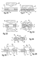
Sur les fig.14 à fig.19, les moyens de fixation comprennent des organes coopérants. L'un de ces organes est constitué d'un pion (24) à tête (25) de poinçonnage, l'autre organe étant constitué d'une cuvette à rebord (26) pour la réception de l'extrémité perforante (27) du pion (24). Sur les fig.15 et fig.18, un outil de frappe (28) enfonce le pion (24) à travers les plaques (4,5). Une enclume (29) est disposée contre la plaque correspondante (5) pour empêcher une déformation des plaques (4,5). L'enclume (29) comporte un évidement (29'), préférentiellement circulaire, pour permettre le passage d'un reflux de matière issu des plaques (4,5) lors de la mise en place du pion (24). Sur les fig.16 et fig.19, la cuvette à rebord (26) est rapportée en étant maintenue par une première électrode (30). Une deuxième électrode (31) est placée contre la tête (25) du pion (24), pour souder l'un à l'autre le pion (24) et la cuvette (26). Cette opération de soudage est susceptible d'être réalisée par décharge de condensateur par exemple. L'extrémité perforante (27) et la cuvette (26) comportent des surfaces d'appui à portée conique, par l'intermédiaire desquelles elles sont soudées l'une à l'autre. Sur la variante de réalisation représentée sur les fig.14 à fig.16, le pion (24) est plein. Sur la variante de réalisation représentée sur les fig.17 à fig.19, le pion (24) est axialement évidé, l'évidement constituant le cas échéant un couloir (21) de passage d'une tige (22) d'un outil (23) d'éjection de la matière découpée des plaques (4,5), tel que précédemment décrit en relation avec la variante de réalisation représentée sur la fig.13. De telles modalités de fixation des plaques (4,5) entre elles mettant en oeuvre une technique de soudage permet l'obtention d'un assemblage des plaques (4,5) fiable et pérenne, sans que l'opération de soudage n'affecte la couche interne de résine (1).In Fig.14 to Fig.19, the fixing means comprise cooperating members. One of these members is constituted by a pin (24) with a punching head (25), the other member being constituted by a flanged bowl (26) for receiving the perforating end (27) of the pawn (24). In fig.15 and fig.18, a striking tool (28) pushes the pin (24) through the plates (4,5). An anvil (29) is disposed against the corresponding plate (5) to prevent deformation of the plates (4,5). The anvil (29) has a recess (29 '), preferably circular, to allow the passage of a material reflux from the plates (4,5) during the establishment of the pin (24). In Fig.16 and Fig.19, the rim cup (26) is attached by being held by a first electrode (30). A second electrode (31) is placed against the head (25) of the pin (24) to weld the pin (24) and the bowl (26) together. This welding operation can be performed by capacitor discharge for example. The piercing end (27) and the bowl (26) have conical bearing bearing surfaces, through which they are welded to each other. On the embodiment shown in Fig.14 to fig.16, the pin (24) is full. In the embodiment variant shown in FIGS. 17 to 19, the pin (24) is axially hollowed out, the recess possibly constituting a passage (21) for the passage of a rod (22) of a tool. (23) ejection of the cut material of the plates (4,5), as previously described in connection with the embodiment variant shown in Fig.13. Such methods of fixing the plates (4, 5) together using a welding technique makes it possible to obtain a reliable and durable assembly of the plates (4, 5), without the welding operation affecting the inner layer of resin (1).
Sur les fig.20 à fig.29, les plaques (4,5) sont assemblées entre elles par l'intermédiaire d'une platine (32) placée en superposition contre une première plaque (4). La platine (32) comporte des languettes (33) formées par découpage et pliage. Les languettes (33) sont susceptibles d'être alignées, ou d'être disposées en quinconce pour un maintien plus équilibré des plaques (4,5) entre elles. Des découpes (34) sont préalablement ménagées à travers les plaques (4,5), pour le passage à leur travers des languettes (33) vers la tôle extérieure (2) de la deuxième plaque (5). Selon la variante de réalisation illustrée sur les fig.20 à fig.23, une seule platine (32) est placée contre l'une des plaques (4), tandis que selon les variantes de réalisation illustrées sur les fig.24 à fig.29, les plaques (4,5) sont munies d'une platine (32) respective, dont les languettes (33) sont rabattues de l'une vers l'autre des plaques (4,5).In FIGS. 20 to 29, the plates (4, 5) are assembled together by means of a plate (32) superposed on a first plate (4). The plate (32) comprises tabs (33) formed by cutting and folding. The tabs (33) are likely to be aligned, or to be arranged in staggered rows for a more balanced maintenance of the plates (4,5) between them. Cutouts (34) are provided beforehand through the plates (4, 5) for passage through the tabs (33) to the outer sheet (2) of the second plate (5). According to the alternative embodiment illustrated in Fig.20 to Fig.23, a single plate (32) is placed against one of the plates (4), while according to the embodiments shown in Fig.24 to Figs. 29, the plates (4,5) are provided with a respective plate (32), the tongues (33) are folded from one to the other of the plates (4,5).
Selon les variantes de réalisation respectivement illustrées sur les fig.20 à fig.23, et sur les fig.24 et fig.25, les languettes (33) comportent un repli (35) de prise d'appui contre la face extérieure de la tôle extérieure (2) de la deuxième plaque (5). Sur les fig.24 et fig.25, cette prise d'appui est réalisée par l'intermédiaire de la platine (32) dont est munie la deuxième plaque (5).According to the embodiments respectively illustrated in Fig.20 to Fig.23, and in Fig.24 and Fig.25, the tabs (33) comprise a fold (35) of bearing against the outer face of the outer plate (2) of the second plate (5). In fig.24 and fig.25, this support is made through the plate (32) which is provided with the second plate (5).
Selon la variante de réalisation illustrée sur les fig.26 à fig.29, les platines (32) sont placées en superposition contre une tôle extérieure (2) d'une plaque respective (4,5). Pour chacune des découpes (34) ménagées à travers les plaques (4,5), les languettes (33) d'une platine (32) sont déformées vers les languettes (33) de l'autre platine (32), au moyen d'électrodes non représentées sur les figures. Les languettes (33) sont non seulement déformées pour prendre appui l'une contre l'autre par l'intermédiaire d'un retour (33'), mais aussi sont soudées entre elles sous pression.According to the alternative embodiment illustrated in Fig.26 to Fig.29, the plates (32) are placed in superposition against an outer sheet (2) of a respective plate (4,5). For each of the cuts (34) formed through the plates (4,5), the tongues (33) of a plate (32) are deformed towards the tongues (33) of the other plate (32), by means of electrodes not shown in the figures. The tongues (33) are not only deformed to bear against each other via a return (33 '), but also are welded together under pressure.
Sur les fig.30 et fig.31, une découpe (36) est ménagée à travers une première plaque (4), et une platine (37) est placée en superposition contre cette plaque (4). Une électrode (38) déforme la platine (37) pour former un relief (39), qui s'étend à travers la découpe (36) jusqu'à la tôle intérieure (3) de la deuxième plaque (5). Le relief (39) est fixé à la tôle intérieure (3) de la deuxième plaque (5) par l'intermédiaire d'un joint de soudure (40). Selon une variante de réalisation, le relief (39) est formé par emboutissage préalablement à la mise en place de la platine (37) contre la première plaque (4).In Fig.30 and Fig.31, a cutout (36) is formed through a first plate (4), and a plate (37) is superimposed against this plate (4). An electrode (38) deforms the plate (37) to form a relief (39) which extends through the cutout (36) to the inner plate (3) of the second plate (5). The relief (39) is attached to the inner plate (3) of the second plate (5) via a solder joint (40). According to an alternative embodiment, the relief (39) is formed by stamping prior to the establishment of the plate (37) against the first plate (4).
Sur les fig.32 et fig.33, une découpe (41) est ménagée à travers les deux plaques (4,5). Une platine (42) respective est placée contre la tôle extérieure (2) de chacune des plaques (4,5). Deux électrodes (43) déforment une platine (42) respective pour former des reliefs conformés en cuvette à rebord (44). Ces cuvettes (44) s'étendent à travers la découpe (41) jusqu'à leur mise en contact en zone médiane de cette dernière. Les reliefs (44) sont soudés l'un à l'autre par leur fond au moyen d'un joint de soudure (45).In fig.32 and fig.33, a cutout (41) is formed through the two plates (4,5). A respective plate (42) is placed against the outer plate (2) of each of the plates (4,5). Two electrodes (43) deform a respective plate (42) to form reliefs shaped flanged bowl (44). These cups (44) extend through the cutout (41) until they are brought into contact in the middle zone of the latter. The reliefs (44) are welded to each other by their bottom by means of a weld joint (45).
Sur la fig.34 les platines sont susceptibles d'être remplacées par un jeu de rondelles (46) conformées en cuvette à rebord (44), ou des rondelles incurvées de type belleville par exemple, dont les collerettes (47) prennent respectivement appui contre les tôles extérieures (2) des plaques (4,5). Ces rondelles (46) sont fixées l'une à l'autre par leur fond par l'intermédiaire d'un joint de soudure (48), au moyen d'électrodes non représentées. Selon une variante de réalisation, les rondelles (46) sont planes et sont déformées par des outils et/ou des électrodes, similaires aux électrodes (43) illustrées sur la fig.32, jusqu'à la mise en contact de leur fond.In FIG. 34, the plates may be replaced by a set of washers (46) shaped as a flanged bowl (44), or curved washers of the Belleville type, for example, whose flanges (47) respectively bear against each other. the outer plates (2) of the plates (4,5). These washers (46) are fixed to each other by their bottom by means of a weld joint (48), by means of electrodes not shown. According to an alternative embodiment, the washers (46) are planar and are deformed by tools and / or electrodes, similar to the electrodes (43) illustrated in FIG. 32, until their bottoms are brought into contact.
Sur les fig.35 et fig.36, une découpe (41) est préalablement ménagée à travers les plaques (4,5). Celles-ci sont fixées l'une à l'autre au moyen d'organes coopérants respectivement affectés à chacune des plaques (4,5). L'un de ces organes est formé d'un premier corps plein épaulé (49), l'autre organe étant formé d'un deuxième corps épaulé (50), qui est axialement évidé. Les corps (49,50) prennent appui contre la tôle extérieure (2) de la plaque (4,5) à laquelle ils sont affectés par l'intermédiaire de leur épaulement (51), et s'étendent partiellement à travers la découpe (41), jusqu'à leur mise en contact l'un contre l'autre. Le corps plein (49) comporte une première surface à portée conique (52). Le corps évidé (50) et le corps plein (49) sont successivement introduits à l'intérieur de la découpe (41), puis le corps plein (49) est pressé contre le corps évidé (50) par l'intermédiaire de sa surface à portée conique (52), jusqu'à écrasement de l'arête intérieure (53) de l'extrémité correspondante du corps évidé (50), formant sur ce dernier une deuxième surface à portée conique coopérante avec la première. Cet écrasement est notamment réalisé au moyen d'électrodes affectées à chacun des corps (49,50), pour les fixer l'un à l'autre par soudage sous pression, par décharge de condensateur par exemple.In fig.35 and fig.36, a cutout (41) is previously formed through the plates (4,5). These are fixed to each other by means of cooperating members respectively assigned to each of the plates (4,5). One of these members is formed of a first stepped solid body (49), the other member being formed of a second shouldered body (50), which is axially recessed. The bodies (49,50) bear against the outer plate (2) of the plate (4,5) to which they are assigned via their shoulder (51), and extend partially through the cutout ( 41) until they come into contact with each other. The solid body (49) has a first conical bearing surface (52). The hollow body (50) and the solid body (49) are successively introduced inside the cutout (41), then the solid body (49) is pressed against the hollow body (50) via its surface. conical bearing (52), until crushing of the inner edge (53) of the corresponding end of the recessed body (50), forming thereon a second conical bearing surface cooperating with the first. This crushing is in particular carried out by means of electrodes assigned to each of the bodies (49,50), to fix them to each other by pressure welding, by capacitor discharge for example.
D'une manière générale pour les différents modes de réalisation représentés sur les fig.26 à fig.36, la pression associée au passage du courant provoque une fusion locale de la matière des éléments en contact l'un contre l'autre, qui crée un joint de soudure. Les zones de pression entre les éléments et les tôles extérieures des plaques contre lesquelles ils prennent respectivement appui, favorisent un assemblage robuste des plaques entre elles. Ce mode d'assemblage est rapide à mettre en oeuvre et provoque un faible dégagement thermique, préservant les plaques et notamment les couches intérieures de résine. En outre, aucune pollution n'est générée. De surcroît, il n'est pas nécessaire d'imposer des tolérances précises de concentricité et de coaxialité de l'une à l'autre des découpes respectivement ménagées à travers les plaques.In general, for the different embodiments shown in FIGS. 26 to 32, the pressure associated with the flow of current causes a local melting of the material of the elements in contact with one another, which creates a solder joint. The pressure zones between the elements and the outer plates of the plates against which they respectively support, promote a robust assembly of the plates together. This method of assembly is quick to implement and causes a low thermal clearance, preserving the plates and in particular the inner layers of resin. In addition, no pollution is generated. In addition, it is not necessary to impose precise tolerances of concentricity and coaxiality from one to the other of the cuts respectively formed through the plates.
Sur les fig.37 et fig.38, la découpe (54) est ménagée à travers une première plaque (4). Cette découpe (54) est sur l'exemple de réalisation illustré de forme oblongue, mais pourrait présenter une quelconque conformation. Un joint de soudure (55), notamment réalisé par apport de matière, est ménagé en bordure de la découpe (54) en étant en prise sur les tôles intérieures (3) superposées des plaques (4,5). Selon une variante de réalisation, le joint de soudure (55) est obtenu à partir de la fusion des tôles intérieures (3) de chacune des plaques (4,5), sans apport de matière. Dans le cas contraire, l'apport de matière est notamment réalisé par brasage ou soudo-brasage LASER, qui permet d'obtenir une fixation des plaques (4,5) entre elles sans détérioration de la couche interne en résine (1), grâce à la focalisation précise du faisceau LASER sur les zones à souder, et notamment sur les tranches des tôles intérieures (3) des plaques (4,5). De préférence, le faisceau LASER est un faisceau de type YAG, qui est notamment véhiculé par fibre optique. La tête de soudure est préférentiellement installée sur un bras à manoeuvre automatique équipé d'un système de détection et de suivi du joint de soudure (55) pratiqué. La matière d'apport est un métal, préférentiellement de type cuivre-silicium-manganèse ou du type cuivre-étain par exemple, pour permettre une fusion basse température de la matière d'apport. Les découpes (54) sont susceptibles d'être ménagées à travers la première plaque (4) de manière régulière ou irrégulière, en étant alignées ou disposées en quinconce. Selon une variante de réalisation, les découpes (54) sont susceptibles d'être ménagées en alternance dans l'une et dans l'autre des plaques (4,5). Leur position est aussi susceptible d'être relativement quelconque, sans tolérances précises, grâce à la fixation des plaques (4,5) entre elles par soudage d'un bord de la découpe (54) ménagée dans une seule des plaques (4). En outre, aucune pollution n'est induite.In fig.37 and fig.38, the cutout (54) is formed through a first plate (4). This cutout (54) is on the illustrated embodiment of oblong shape, but could have any conformation. A solder joint (55), in particular made by adding material, is formed at the edge of the cutout (54) by being engaged on the inner sheets (3) superimposed plates (4,5). According to an alternative embodiment, the weld joint (55) is obtained from the fusion of the inner sheets (3) of each of the plates (4,5), without adding material. In the opposite case, the material supply is in particular carried out by soldering or brazing LASER, which makes it possible to obtain a fixing of the plates (4,5) between them without deterioration of the inner layer of resin (1), thanks to the precise focusing of the LASER beam on the areas to be welded, and in particular on the slices of the inner plates (3) of the plates (4,5). Preferably, the LASER beam is a YAG beam, which is in particular conveyed by optical fiber. The welding head is preferably installed on an arm with automatic operation equipped with a system for detecting and monitoring the welding joint (55) practiced. The filler material is a metal, preferably copper-silicon-manganese type or copper-tin type for example, to allow a low temperature melting of the filler material. The cutouts (54) are likely to be formed through the first plate (4) in a regular or irregular manner, being aligned or arranged in staggered rows. According to an alternative embodiment, the cutouts (54) may be alternately formed in one and the other of the plates (4,5). Their position is also likely to be relatively arbitrary, without precise tolerances, by fixing the plates (4,5) together by welding an edge of the blank (54) formed in only one of the plates (4). In addition, no pollution is induced.
Sur les fig.39 et fig.40, la découpe (56) est ménagée dans l'une des plaques (4,5), en bordure de cette dernière. Un joint de soudure (57), réalisé par apport de matière, est ménagé le long du bord de la découpe (56). Ce joint de soudure (57) est notamment un cordon de soudure réalisé par brasage ou soudobrasage, notamment par brasage LASER à la manière de la variante de réalisation décrite sur les fig.37 et fig.38. La découpe (56) est susceptible de présenter une trajectoire rectiligne, sans inflexion. Cependant, il est préféré de conférer à cette découpe (56) une forme irrégulière, telle que sinusoïdale sur l'exemple de réalisation illustré. Les bords respectifs des plaques (4,5) sont décalés l'un par rapport à l'autre, la distance de séparation entre ces bords étant susceptible d'être indifféremment constante ou variable. Une telle conformation de la découpe (56) permet une bonne tenue en pelage des plaques (4,5) assemblées.In fig.39 and fig.40, the cutout (56) is formed in one of the plates (4,5), at the edge thereof. A solder joint (57) made by adding material is provided along the edge of the blank (56). This solder joint (57) is in particular a weld bead made by brazing or brazing, in particular by brazing LASER in the manner of the variant embodiment described in FIGS. 37 and 39. The cutout (56) is likely to have a rectilinear trajectory, without inflection. However, it is preferred to give this cutout (56) an irregular shape, such as sinusoidal in the illustrated embodiment. The respective edges of the plates (4,5) are offset relative to each other, the separation distance between these edges being capable of being indifferently constant or variable. Such a conformation of the cutout (56) allows a good peel strength of the plates (4,5) assembled.
Sur la fig.41, la découpe (56) ménagée dans la plaque (4) présente un retour (56') vers l'extérieur de la plaque (5). Ces dispositions sont telles que la surface de contact entre le joint de soudure (57) et la tôle intérieure (3) de la plaque (4) est optimisée pour améliorer la prise du joint de soudure (57) sur la plaque (4) et finalement favoriser une stabilité du soudage. Selon diverses variantes de réalisation, soit les deux tôles intérieure (3) et extérieure (2) de la plaque (4) sont recourbées, tel qu'illustré sur la fig.41, soit uniquement la tôle intérieure (3) de la plaque (4) présente une inflexion.In fig.41, the cutout (56) formed in the plate (4) has a return (56 ') towards the outside of the plate (5). These arrangements are such that the contact surface between the solder joint (57) and the inner plate (3) of the plate (4) is optimized to improve the grip of the solder joint (57) on the plate (4) and finally to promote a stability of the welding. According to various alternative embodiments, the two inner (3) and outer (2) plates of the plate (4) are curved, as illustrated in FIG. 41, or only the inner plate (3) of the plate (FIG. 4) has an inflection.
Sur les fig.42 et fig.43, les plaques (4,5) sont assemblées entre elles orthogonalement dans leur plan général. L'une des plaques (4) comporte des premières découpes (58) ménagées dans sa tranche, pour former des reliefs d'emboîtement (59). L'autre plaque (5) comporte des deuxièmes découpes (60) de forme complémentaire à la conformation des reliefs (59), en vue de l'emboîtement des plaques (4,5) entre elles. Un joint de soudure (61) est ménagé, notamment par brasage ou soudobrasage LASER, en bordure d'une partie émergeante des reliefs (59) hors des deuxièmes découpes (60) ménagées à travers la plaque correspondante (5). Ce cordon de soudure (61) est en prise sur les tôles extérieures (2) des plaques (4,5). Selon une variante de réalisation illustrée sur la fig.44, deux joints de soudure (62,63) sont réalisés de part et d'autre des débouchés de la découpe (60) ménagée à travers la plaque (5). Ces dispositions offrent une meilleure stabilité de soudage des plaques (4,5) entre elles. L'opération de brasage est notamment réalisée à la manière de la variante de réalisation décrite sur les fig.37 et fig.38.In fig.42 and fig.43, the plates (4,5) are joined together orthogonally in their general plane. One of the plates (4) has first cutouts (58) formed in its edge, to form interlocking reliefs (59). The other plate (5) comprises second cutouts (60) of shape complementary to the conformation of the reliefs (59), for the purpose of interlocking the plates (4,5) between them. A solder joint (61) is provided, in particular by brazing or brazing LASER, at the edge of an emerging portion of the reliefs (59) out of the second cutouts (60) formed through the corresponding plate (5). This weld bead (61) is engaged on the outer plates (2) of the plates (4,5). According to an alternative embodiment illustrated in FIG. 44, two solder joints (62, 63) are formed on either side of the outlets of the cutout (60) formed through the plate (5). These arrangements provide better welding stability of the plates (4,5) between them. The brazing operation is in particular carried out in the manner of the variant embodiment described in FIGS. 37 and 39.
Bien qu'il ait été illustré un dispositif d'assemblage de deux plaques (4,5) entre elles, il doit être compris que le nombre de plaques (4,5) peut être quelconque. De même, un quelconque autre matériau conditionné en plaque peut être interposé entre les plaques (4,5) à assembler. Par ailleurs, chaque plaque (4,5) est susceptible de comporter une ou plusieurs couches de matériau interposées entre les tôles métalliques (2,3), tel qu'au moins une autre tôle métallique, au moins une autre couche interne de résine, voire au moins un autre matériau.Although it has been illustrated an assembly device of two plates (4,5) between them, it should be understood that the number of plates (4,5) can be any. Similarly, any other plate-conditioned material may be interposed between the plates (4,5) to be assembled. Furthermore, each plate (4, 5) is capable of comprising one or more layers of material interposed between the metal sheets (2, 3), such as at least one other metal sheet, at least one other internal layer of resin, at least one other material.
Claims (38)
Applications Claiming Priority (1)
| Application Number | Priority Date | Filing Date | Title |
|---|---|---|---|
| FR0509820A FR2891324B1 (en) | 2005-09-26 | 2005-09-26 | ASSEMBLY DEVICE BETWEEN TWO STRATIFIED PLATES COMPRISING A RESIN LAYER INTERPOSED BETWEEN TWO METAL SHEETS |
Publications (2)
| Publication Number | Publication Date |
|---|---|
| EP1767792A2 true EP1767792A2 (en) | 2007-03-28 |
| EP1767792A3 EP1767792A3 (en) | 2007-10-31 |
Family
ID=36218241
Family Applications (1)
| Application Number | Title | Priority Date | Filing Date |
|---|---|---|---|
| EP06120303A Withdrawn EP1767792A3 (en) | 2005-09-26 | 2006-09-07 | Connecting device for two multilayer plates composed from a resin layer between two metal sheets |
Country Status (5)
| Country | Link |
|---|---|
| US (1) | US7937816B2 (en) |
| EP (1) | EP1767792A3 (en) |
| JP (1) | JP2007092999A (en) |
| CN (1) | CN1955497A (en) |
| FR (1) | FR2891324B1 (en) |
Cited By (3)
| Publication number | Priority date | Publication date | Assignee | Title |
|---|---|---|---|---|
| FR2925941A1 (en) * | 2008-01-02 | 2009-07-03 | Thierry Leclair | Flat product and/or sheet e.g. professional document, assembling system for use in office, has opening, whose length is less than sum of heights of assembling zone and one of returns or sum of heights of assembling zone and another return |
| DE102008017981A1 (en) * | 2008-04-04 | 2009-10-08 | Volkswagen Ag | Rivet for riveting e.g. sheet metal, for vehicle, has rivet pins with ends including driving surfaces that are turned away or towards longitudinal axis such that pins are spread apart or towards each other during intended use |
| WO2014173472A1 (en) * | 2013-04-22 | 2014-10-30 | Boellhoff Verbindungstechnik Gmbh | Setting welding machine, modular components thereof and a continuous connecting method that can be carried out with such a machine |
Families Citing this family (17)
| Publication number | Priority date | Publication date | Assignee | Title |
|---|---|---|---|---|
| DE102009045791A1 (en) * | 2009-10-19 | 2011-05-12 | Zf Friedrichshafen Ag | Rivet, riveting device and riveting method |
| DE102011006145A1 (en) * | 2011-03-25 | 2012-09-27 | Federal-Mogul Sealing Systems Gmbh | Composite material with embossing and microperforation |
| CN102760953B (en) * | 2011-04-29 | 2015-09-16 | 深圳光启高等理工研究院 | A kind of Meta Materials package assembly and assemble method thereof |
| US8966734B2 (en) * | 2011-09-23 | 2015-03-03 | GM Global Technology Operations LLC | Method of joining magnesium |
| DE102011122037A1 (en) * | 2011-12-22 | 2013-06-27 | Kathrein-Werke Kg | Method for producing a high-frequency electrical connection between two plate sections and an associated high-frequency electrical connection |
| JP5893955B2 (en) * | 2012-02-27 | 2016-03-23 | 株式会社神戸製鋼所 | Method for manufacturing fastening structure of foamed resin core composite plate |
| KR101483226B1 (en) * | 2013-09-11 | 2015-01-16 | 주식회사 성우하이텍 | Bonding panel and panel bonding method thereof |
| EP2860407B1 (en) * | 2013-10-08 | 2017-01-18 | MAGNA STEYR Fahrzeugtechnik AG & Co KG | Structured component |
| JP6252747B2 (en) * | 2013-11-22 | 2017-12-27 | ポップリベット・ファスナー株式会社 | Joining apparatus and joining method |
| KR101558208B1 (en) | 2013-12-30 | 2015-10-08 | 주식회사 성우하이텍 | Spot welding method of panel |
| DE102014208513B4 (en) * | 2014-05-07 | 2021-01-21 | Bayerische Motoren Werke Aktiengesellschaft | Method for fastening several workpieces by means of a hollow rivet element |
| WO2016101064A1 (en) | 2014-12-23 | 2016-06-30 | Magna International Inc. | Method of laser beam localized-coating |
| KR20170069379A (en) * | 2015-12-10 | 2017-06-21 | 현대자동차주식회사 | Connecting unit for composite |
| US10576532B2 (en) * | 2015-12-14 | 2020-03-03 | GM Global Technology Operations LLC | Systems and methods for joining components by riveting |
| DE102016118109A1 (en) | 2016-09-26 | 2018-03-29 | Newfrey Llc | Joining method for pre-hole-free connection of at least one first component with a second component |
| KR20190051315A (en) * | 2017-11-06 | 2019-05-15 | 울산대학교 산학협력단 | Electrically assisted pressure joining method |
| CN109591895A (en) * | 2018-11-08 | 2019-04-09 | 重庆腾海工贸有限公司 | A kind of top cap rear cross beam component |
Citations (4)
| Publication number | Priority date | Publication date | Assignee | Title |
|---|---|---|---|---|
| DE1125871B (en) * | 1956-07-31 | 1962-03-22 | Edoardo G Bianca | Method for joining sheet metal parts, especially in the manufacture of conically tapering pipe sections for pipe masts |
| DE19540904A1 (en) * | 1994-11-02 | 1996-05-09 | Mitsubishi Chem Corp | Method of riveting thin metal sheets to thicker plates |
| JPH08128425A (en) * | 1994-11-02 | 1996-05-21 | Mitsubishi Chem Corp | Method for construction with rivet and building material obtained by this construction method |
| EP0718068A1 (en) * | 1994-12-23 | 1996-06-26 | FIAT AUTO S.p.A. | Method of connecting different members by welding |
Family Cites Families (18)
| Publication number | Priority date | Publication date | Assignee | Title |
|---|---|---|---|---|
| US2626687A (en) * | 1949-05-23 | 1953-01-27 | Ivan A Williams | Cleft fastener for uniting materials and method of forming the same |
| US2688890A (en) * | 1952-08-09 | 1954-09-14 | Ivan A Williams | Method of uniting superimposed metal sheets |
| US2814481A (en) * | 1952-08-16 | 1957-11-26 | Gen Motors Corp | Laminated spring |
| US2959495A (en) * | 1954-03-11 | 1960-11-08 | Patent & Licensing Corp | Vibration deadening felts |
| US2901816A (en) * | 1955-02-24 | 1959-09-01 | Smith | Tool and method for securing sheet metal pieces together |
| US3010199A (en) * | 1955-02-24 | 1961-11-28 | Smith | Tool and method for securing sheet metal pieces together |
| JPS5429270U (en) * | 1977-07-28 | 1979-02-26 | ||
| JPS56120805A (en) * | 1980-02-26 | 1981-09-22 | Tokyo Shibaura Electric Co | Joining device of plate like member |
| JPS60260713A (en) * | 1984-06-07 | 1985-12-23 | 日本鋼管株式会社 | Clamping of laminate steel plate by clamp means such as bolt |
| US5074726A (en) * | 1988-11-28 | 1991-12-24 | The B. F. Goodrich Company | Blind fastener |
| US4828438A (en) * | 1988-03-17 | 1989-05-09 | The B.F. Goodrich Company | Blind fastener |
| JP3287715B2 (en) * | 1994-11-30 | 2002-06-04 | 三菱化学株式会社 | Rivet installation method |
| US6235409B1 (en) * | 1997-12-17 | 2001-05-22 | Alcoa Inc. | Aluminum laminate |
| JP2000081011A (en) * | 1998-09-04 | 2000-03-21 | Fukui Byora Co Ltd | Method for caulking-fastening plastic corrugated fiberboard and reinforcing plate together, punch for caulking used in the method, and plastic corrugated fiberboard box produced by this method |
| JP2001099113A (en) * | 1999-09-27 | 2001-04-10 | Nippon Steel Corp | Mechanical connection method for plated steel plate and painted steel plate and connecting material |
| US6365276B1 (en) * | 1999-11-12 | 2002-04-02 | Mitsushita Chemical America, Inc. | Coated metal articles methods for preparing the same laminated composites containing the same, and methods for preparing such laminated composites |
| JP2002070892A (en) * | 2000-08-31 | 2002-03-08 | Mitsubishi Heavy Ind Ltd | Magnetic clutch and compressor having its magnetic clutch |
| WO2006102592A1 (en) * | 2005-03-24 | 2006-09-28 | 3M Innovative Properties Company | Metallized films and articles containing the same |
-
2005
- 2005-09-26 FR FR0509820A patent/FR2891324B1/en not_active Expired - Fee Related
-
2006
- 2006-09-07 EP EP06120303A patent/EP1767792A3/en not_active Withdrawn
- 2006-09-12 US US11/519,263 patent/US7937816B2/en not_active Expired - Fee Related
- 2006-09-26 JP JP2006259837A patent/JP2007092999A/en active Pending
- 2006-09-26 CN CNA2006101395687A patent/CN1955497A/en active Pending
Patent Citations (4)
| Publication number | Priority date | Publication date | Assignee | Title |
|---|---|---|---|---|
| DE1125871B (en) * | 1956-07-31 | 1962-03-22 | Edoardo G Bianca | Method for joining sheet metal parts, especially in the manufacture of conically tapering pipe sections for pipe masts |
| DE19540904A1 (en) * | 1994-11-02 | 1996-05-09 | Mitsubishi Chem Corp | Method of riveting thin metal sheets to thicker plates |
| JPH08128425A (en) * | 1994-11-02 | 1996-05-21 | Mitsubishi Chem Corp | Method for construction with rivet and building material obtained by this construction method |
| EP0718068A1 (en) * | 1994-12-23 | 1996-06-26 | FIAT AUTO S.p.A. | Method of connecting different members by welding |
Non-Patent Citations (1)
| Title |
|---|
| PATENT ABSTRACTS OF JAPAN vol. 1996, no. 09, 30 septembre 1996 (1996-09-30) & JP 08 128425 A (MITSUBISHI CHEM CORP; JAPAN DRIVE-IT CO LTD), 21 mai 1996 (1996-05-21) * |
Cited By (5)
| Publication number | Priority date | Publication date | Assignee | Title |
|---|---|---|---|---|
| FR2925941A1 (en) * | 2008-01-02 | 2009-07-03 | Thierry Leclair | Flat product and/or sheet e.g. professional document, assembling system for use in office, has opening, whose length is less than sum of heights of assembling zone and one of returns or sum of heights of assembling zone and another return |
| DE102008017981A1 (en) * | 2008-04-04 | 2009-10-08 | Volkswagen Ag | Rivet for riveting e.g. sheet metal, for vehicle, has rivet pins with ends including driving surfaces that are turned away or towards longitudinal axis such that pins are spread apart or towards each other during intended use |
| WO2014173472A1 (en) * | 2013-04-22 | 2014-10-30 | Boellhoff Verbindungstechnik Gmbh | Setting welding machine, modular components thereof and a continuous connecting method that can be carried out with such a machine |
| US10207458B2 (en) | 2013-04-22 | 2019-02-19 | Böllhoff Verbindungstechnik GmbH | Setting welding device, modular components thereof and a continuous connecting method that can be carried out with such a device |
| US11084229B2 (en) | 2013-04-22 | 2021-08-10 | Böllhoff Verbindungstechnik GmbH | Setting welding device, modular components thereof and a continuous connecting method that can be carried out with such a device |
Also Published As
| Publication number | Publication date |
|---|---|
| US7937816B2 (en) | 2011-05-10 |
| JP2007092999A (en) | 2007-04-12 |
| US20070068116A1 (en) | 2007-03-29 |
| FR2891324B1 (en) | 2011-02-18 |
| EP1767792A3 (en) | 2007-10-31 |
| CN1955497A (en) | 2007-05-02 |
| FR2891324A1 (en) | 2007-03-30 |
Similar Documents
| Publication | Publication Date | Title |
|---|---|---|
| EP1767792A2 (en) | Connecting device for two multilayer plates composed from a resin layer between two metal sheets | |
| US10118254B2 (en) | Manufacturing method for a side body structure of a vehicle and a side body structure of a vehicle | |
| US20110097142A1 (en) | Weld Rivet Joint | |
| EP2416946B1 (en) | Process for manufacturing a stiffened panel made of a thermoplastic matrix composite material and resulting panel | |
| EP3618995B1 (en) | Insert intended for assembling a first part and a second part by electric resistance welding, and assembly method using this insert | |
| EP2656150B1 (en) | Assembly process of a component which does not have a plastic domain | |
| JP6101513B2 (en) | Metal foil lap joint method and joint structure | |
| EP2674286A1 (en) | Method and device for placing an insert in a thermoplastic composite material | |
| FR2802453A1 (en) | SELF-WELDING ASSEMBLY OF SHEETS, OF THE BUTTONING TYPE | |
| EP3185086B1 (en) | Timepiece dial applique | |
| EP0340094B1 (en) | Process for joining by riveting a first part made of plastic to a second part. | |
| EP2829385A1 (en) | Combined riveting and punching method | |
| EP3538313B1 (en) | Method for magnetic pulse welding of a stack of sheets | |
| EP3145795B1 (en) | Motor vehicle roof braze welded to the sides of the body shell | |
| EP3448694B1 (en) | Motor vehicle wheel having an aluminium rim and a steel wheel disc joined together by welded pins | |
| WO2018193839A1 (en) | Joined body, seat frame for automobile, and joining method | |
| FR3084120A1 (en) | FIXING COMPONENT, ASSEMBLY METHOD AND ASSEMBLY DEVICE | |
| FR2702528A1 (en) | Brake pads with studs with improved fixing. | |
| JP2018179281A (en) | Joint body, seat frame for automobile and joining method | |
| WO2023062296A1 (en) | Method for joining two sheet-metal parts together by adhesive bonding and welding | |
| EP4174330A1 (en) | Method and attachment for assembling at least two basic parts | |
| WO2009133305A1 (en) | Method and device for attaching an apparatus onto a compressible coating covering a mounting structure | |
| WO2009037411A2 (en) | Door band for automobile, door for automobile and methods for making same | |
| EP3801970A1 (en) | Method for assembling a first part and a second part by means of an insert | |
| FR3006921A1 (en) | METHOD FOR ASSEMBLING PLATES |
Legal Events
| Date | Code | Title | Description |
|---|---|---|---|
| PUAI | Public reference made under article 153(3) epc to a published international application that has entered the european phase |
Free format text: ORIGINAL CODE: 0009012 |
|
| AK | Designated contracting states |
Kind code of ref document: A2 Designated state(s): AT BE BG CH CY CZ DE DK EE ES FI FR GB GR HU IE IS IT LI LT LU LV MC NL PL PT RO SE SI SK TR |
|
| AX | Request for extension of the european patent |
Extension state: AL BA HR MK YU |
|
| PUAL | Search report despatched |
Free format text: ORIGINAL CODE: 0009013 |
|
| AK | Designated contracting states |
Kind code of ref document: A3 Designated state(s): AT BE BG CH CY CZ DE DK EE ES FI FR GB GR HU IE IS IT LI LT LU LV MC NL PL PT RO SE SI SK TR |
|
| AX | Request for extension of the european patent |
Extension state: AL BA HR MK YU |
|
| AKX | Designation fees paid | ||
| REG | Reference to a national code |
Ref country code: DE Ref legal event code: 8566 |
|
| STAA | Information on the status of an ep patent application or granted ep patent |
Free format text: STATUS: THE APPLICATION IS DEEMED TO BE WITHDRAWN |
|
| 18D | Application deemed to be withdrawn |
Effective date: 20080503 |