EP1766206B1 - Unite d'entretien du liquide de refroidissement pourvue d'un clapet antiretour - Google Patents
Unite d'entretien du liquide de refroidissement pourvue d'un clapet antiretour Download PDFInfo
- Publication number
- EP1766206B1 EP1766206B1 EP05767862A EP05767862A EP1766206B1 EP 1766206 B1 EP1766206 B1 EP 1766206B1 EP 05767862 A EP05767862 A EP 05767862A EP 05767862 A EP05767862 A EP 05767862A EP 1766206 B1 EP1766206 B1 EP 1766206B1
- Authority
- EP
- European Patent Office
- Prior art keywords
- housing
- coolant
- cover
- stop valve
- filter
- Prior art date
- Legal status (The legal status is an assumption and is not a legal conclusion. Google has not performed a legal analysis and makes no representation as to the accuracy of the status listed.)
- Not-in-force
Links
- 239000002826 coolant Substances 0.000 title claims abstract description 54
- 230000003750 conditioning effect Effects 0.000 title abstract 2
- 238000002485 combustion reaction Methods 0.000 claims abstract 2
- 230000000717 retained effect Effects 0.000 claims abstract 2
- 238000007789 sealing Methods 0.000 claims description 6
- 239000011324 bead Substances 0.000 claims description 5
- 238000006073 displacement reaction Methods 0.000 description 4
- 230000001419 dependent effect Effects 0.000 description 3
- 239000000654 additive Substances 0.000 description 1
- 230000000712 assembly Effects 0.000 description 1
- 238000000429 assembly Methods 0.000 description 1
- 230000000903 blocking effect Effects 0.000 description 1
- 239000002131 composite material Substances 0.000 description 1
- 230000007797 corrosion Effects 0.000 description 1
- 238000005260 corrosion Methods 0.000 description 1
- 230000006735 deficit Effects 0.000 description 1
- 230000000694 effects Effects 0.000 description 1
- 238000001914 filtration Methods 0.000 description 1
- 239000003112 inhibitor Substances 0.000 description 1
- 239000007788 liquid Substances 0.000 description 1
- 238000012423 maintenance Methods 0.000 description 1
- 238000004519 manufacturing process Methods 0.000 description 1
- 239000000463 material Substances 0.000 description 1
- 238000010992 reflux Methods 0.000 description 1
- 230000002787 reinforcement Effects 0.000 description 1
- 238000013022 venting Methods 0.000 description 1
Images


Classifications
-
- F—MECHANICAL ENGINEERING; LIGHTING; HEATING; WEAPONS; BLASTING
- F01—MACHINES OR ENGINES IN GENERAL; ENGINE PLANTS IN GENERAL; STEAM ENGINES
- F01P—COOLING OF MACHINES OR ENGINES IN GENERAL; COOLING OF INTERNAL-COMBUSTION ENGINES
- F01P11/00—Component parts, details, or accessories not provided for in, or of interest apart from, groups F01P1/00 - F01P9/00
- F01P11/06—Cleaning; Combating corrosion
-
- B—PERFORMING OPERATIONS; TRANSPORTING
- B01—PHYSICAL OR CHEMICAL PROCESSES OR APPARATUS IN GENERAL
- B01D—SEPARATION
- B01D35/00—Filtering devices having features not specifically covered by groups B01D24/00 - B01D33/00, or for applications not specifically covered by groups B01D24/00 - B01D33/00; Auxiliary devices for filtration; Filter housing constructions
- B01D35/14—Safety devices specially adapted for filtration; Devices for indicating clogging
- B01D35/153—Anti-leakage or anti-return valves
-
- F—MECHANICAL ENGINEERING; LIGHTING; HEATING; WEAPONS; BLASTING
- F01—MACHINES OR ENGINES IN GENERAL; ENGINE PLANTS IN GENERAL; STEAM ENGINES
- F01P—COOLING OF MACHINES OR ENGINES IN GENERAL; COOLING OF INTERNAL-COMBUSTION ENGINES
- F01P11/00—Component parts, details, or accessories not provided for in, or of interest apart from, groups F01P1/00 - F01P9/00
- F01P11/06—Cleaning; Combating corrosion
- F01P2011/061—Cleaning or combating corrosion using filters
Definitions
- the invention relates to a coolant care unit according to the preamble of claim 1.
- Such coolant care units are for example from the practice and from the US 5,753,116 known. On the one hand, they offer the possibility of extending the service life by filtering the coolant.
- care units is usually provided to use when changing the filter cartridge with a care product, which is automatically opened when using the filter insert into the housing and introduces care additives in the coolant circuit, for example, so-called “inhibitors” which serve, for example, as frost and corrosion protection can.
- the so-called filter change in such coolant care units ie the change of the filter insert, when the coolant is still a relatively high temperature and the coolant system is under pressure.
- the invention has for its object to improve a generic coolant care unit to the effect that this allows a safe replacement of the filter cartridge and in particular a safe opening of the coolant filter.
- This object is achieved by a coolant care unit having the features of claim 1.
- the invention proposes to shut off the interior of the filter housing from the rest of the coolant circuit so that overpressure prevailing in the coolant circuit can not result in hot coolant leaking out of the filter housing when the cover is removed from the housing.
- the pressure prevailing in the filter housing itself pressure is reduced by the fact that the lid is removed and meanwhile the coolant in the filter housing can relax before the lid is completely removed and the seal composite between the lid and housing is repealed.
- a check valve may be provided so that, driven by the coolant pump, during normal operation on the clean side of the coolant filter, there is a greater pressure than in the rest of the coolant circuit, where the "remaining coolant circuit" the points of the coolant circuit in the present proposal be understood that connect directly to the aforementioned, proposed by the proposed valves. Due to the pressure difference, the check valve opens during normal operation. In a filter change or when the coolant filter is opened for other reasons and the pressure inside the filter is relaxed, there is a lower pressure than in the rest of the coolant circuit, so that the aforementioned check valve blocks in the return.
- a check valve is provided, which is not pressure-actuated, but opens and closes away.
- the movable valve body of this check valve pushed into its open position. If the cover is removed from the housing, while the filter insert is also moved at the same time, which is connected to the lid, for example by a clip connection.
- a movement of the valve body may also be provided solely due to the pressure prevailing in the rest of the coolant circuit, so that when the filter cartridge is removed from the valve body, the check valve will not remain forcibly opened, but will be forced into its closed position following the pressure in the coolant circuit can be.
- the filter element can be configured in a manner known per se as an approximately cylindrical insert with an upper end plate, which has, for example, the locking means for connection to the lid and with a lower end plate, which rests as a pressure plate the valve body or indirectly or directly on the valve body acts and pushes it in its open position when the filter cartridge is in its operating position.
- a plunger may be provided, which adjoins the valve body and extends to the end plate of the filter insert.
- a plunger may be provided, which adjoins the valve body and extends to the end plate of the filter insert.
- the aforesaid end plate may preferably be reinforced in the region which acts on the check valve.
- the end plate can be basically designed to save material, while it is stiffened only in the required area, which acts on the check valve, so that a reliable actuation of the check valve is ensured and deformations of the end plate, as they occur under operating temperatures and Pressing could occur are excluded.
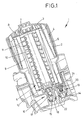
- a total of a coolant care unit This has a cup-shaped housing 2 and a lid 3, which is designed as a screw cap and is screwed to the housing 2. Between cover 3 and housing 2, a circumferential O-ring seal 4 is provided.
- the cover 3 has a displacement body 5, which prevents the interior of the housing 2 can be completely filled with coolant. Upon removal of the cover 3 from the housing 2, therefore, the liquid level inside the housing is lowered automatically, so that is ensured even at inclinations of the housing 2 in a normal operation during operation, that no coolant can flow over the top of the housing 2, but reliable remains within the housing 2.
- a filter insert 6 is connected to the cover 3, specifically via a latching connection 7, which is provided on an upper end disk 8 of the filter element 6, which is generally cylindrical in shape.
- the filter insert 6 has a filter medium 9 in the form of, for example, a paper fold filter and an inner support dome 10, which has passage openings 11. At its lower end, the filter cartridge 6 has a lower end plate 12.
- the coolant flows through an inlet 14 radially outside the filter insert 6 into the housing 2. It passes after passing through the filter medium 9 in the interior of the filter cartridge 6 and flows there through a return line 15 back.
- a check valve 16 is provided with a valve body designed as a ball 17.
- the check valve 16 is designed as a so-called float valve.
- the ball 17 is in the operating state shown in the drawing a lower stop 18 at. It can be lifted by the action of its buoyancy and by the prevailing pressure in the rest of the coolant circuit and pressed against its valve seat when the inside of the housing 2 and in particular in the interior, on the clean side of the filter cartridge 6 prevailing pressure correspondingly low compared to the pressure otherwise Coolant circuit below the ball 17 is.
- inlet 14 is a particular from the Fig. 2 and 4 closer apparent check valve 19 is provided.
- This has a movable valve body 20 and a collar-shaped valve seat 21.
- the valve body 20 is connected to a plunger 22, against which the lower end plate 12 abuts.
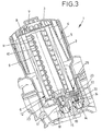
- the lower end plate 12 is in the embodiment of Fig. 3 and 4 reinforced along its outer periphery by a lower circumferential bead 23 and stiffened in this way, so that they are not deformed under the pressure of the plunger 22 and an impermissible closing movement of the check valve 19 allows.
- the bead 23 forms a guide groove 25, in which the upper end of the plunger 22 is guided.
- the closing movement of the check valve 19 is made possible when the lid 3 is unscrewed from the housing 2.
- the filter insert 6 moves together with the cover 3 at the intended in the drawing alignment of the housing 2 upwards.
- the plunger 22 and thus the valve body 20 follow this movement, so that the valve body 20 gets closer to the valve seat 21, the further the lid 3 is released from the housing 2.
- the aforementioned bias of the check valve 19 may be effected either by a spring 24, wherein the valve body 20 is held against the action of this spring 24 through the filter cartridge 6 in its open position, or said bias can be realized by the pressure prevailing in the rest of the coolant circuit pressure, which is greater than the pressure prevailing in the housing 2, in particular, when the effective internal volume of the housing 2 is increased by the cover 3 is unscrewed.
- valve body 20 Due to this pressure difference, the valve body 20, even if the illustrated spring 24 would not be present, pressed into its closed position. However, should the housing 2 be opened when the coolant is cold and thus pressureless, then the check valve 19 would not be closed if the valve body 20 were urged into its closed position exclusively due to the internal pressure in the coolant circuit. In such a case, however, the sudden escape of hot coolant would not be feared, so that an automatic, temperature-dependent and self-regulating function of the check valve 19 would be given.
- the check valve 19 is a travel-operated valve, because the open position of the valve body 20 is in each case forced path-dependent on the position of the filter cartridge.
- the arrangement of the cover 3 provided on the seal 4 is provided so far from the upper edge of the housing 2 spaced, that this distance is greater than the distance which the valve body 20 must cover from its illustrated open position to its closed position. It is therefore ensured that the check valve 19 is closed when, during the removal of the cover 3 from the housing 2, the seal 4 is still sealingly effective. Only in the further course of this decrease movement of the lid 3, the seal 4 reaches the upper edge of the housing 2 and loses its effectiveness. In this case, however, the check and shut-off valves 16 and 19 are closed and due to the displacement body 5 is also reliably ensured that in the interior of the housing 2 just before the seal 4 loses its effectiveness, no overpressure prevails, leading to a sudden escape could cause hot coolant.
- Fig. 5 shows a third embodiment in the ready state, ie with completely screwed into the housing 2 cover 3.
- the displacer 5 is not radially outside provided by the filter element 6, but only above the upper end plate 8 of the filter element 6.
- the radial space can be optimally used within the housing 2, so that either a filter element 6 can be used with very wide folds or the diameter of the housing 2 comparatively low can be kept and can be arranged even in cramped conditions still at an optimal location.
- the axial extent of the coolant care unit 1 is larger by the displacement of the displacement body 5 axially in front of the filter element 6, however, sufficient clearance is usually present in this direction, since accessibility to the cover 3 is provided anyway for maintenance work in this direction.
- a vent line 26 is realized in the lid 3, which leads to a corresponding vent hole 27 in the upper end plate 8 of the filter element 6.
- the vent line 26 is advantageous in terms of production not realized by a bore, but by one or more ribs on the underside of the lid 3, where the lid 3 forms the displacer 5.
- vent lines could be realized by recesses, so grooves in the lower edge of the lid 3, or by corresponding ribs or grooves in the surface of the upper end plate 8.
- the vent line 26 is a short circuit, so a bypass of the filter element 6, so that uncleaned coolant can pass through the vent hole 27 on the clean side of the filter, bypassing the filter insert 6.
- this bypass of the filter insert 6 is no relevant impairment of the filter function.
- vent line 26 Left of the vent line 26 is in the Fig. 5 and 6 in each case a bore 29 can be seen, which extends through the cover 3. It allows, together with the vent line 26 and the vent hole 27, the venting of the housing 2 when the filter insert 6 is inserted into the housing 2 and thereby the air initially in the housing 2 is displaced, through the bore 29, the displaced from the housing 2 Air escape until the seal 4 against the housing 2 and sealingly abuts him.
- the check valve 19 is in the embodiment of Fig. 5 and 6 merely shown, for example, left of the return check valve 16, ie on the opposite side to the other embodiments.
- valve body 20 of the check valve 19 is guided by ribs 28 in the axial direction, wherein these ribs are formed in the housing 2, so that in a technically simple and economically advantageous manner, the leadership of the valve body 20 is ensured.
- the length of the thread between the housing 2 and cover 3 and the position of the seal 4 are - as in particular from the comparison between the Fig. 5 and 6 emerges - coordinated so that the inner and outer threads of the housing 2 and the cover 3 mesh with each other before the sealing ring rests against its provided in the housing 2 sealing surface.
- the seal 4 is also drawn into the housing 2 when the lid 3 is screwed into the housing 2. This facilitates on the one hand the handling when screwing in the lid 3 and also ensures that a kind of centering of the lid 3 is effected by the thread, so that a uniform possible contact of the seal 4 takes place around the associated sealing surface of the housing 2 and an excessive, one-sided Load on the seal 4 is avoided, which could possibly lead to damage to the seal.
Landscapes
- Engineering & Computer Science (AREA)
- Chemical & Material Sciences (AREA)
- Combustion & Propulsion (AREA)
- Mechanical Engineering (AREA)
- General Engineering & Computer Science (AREA)
- Chemical Kinetics & Catalysis (AREA)
- Details Of Valves (AREA)
- Check Valves (AREA)
- Lubrication Details And Ventilation Of Internal Combustion Engines (AREA)
- Filtration Of Liquid (AREA)
Abstract
Claims (8)
- Unité (1) servant à entretenir le fluide de refroidissement d'une machine à combustion interne,
comprenant un carter (2) en forme de gobelet,
un couvercle (3) amovible obturant le carter (2),
une cartouche filtrante (6) interchangeable agencée dans le carter (2), retenue de manière détachable contre le couvercle (3),
un orifice (14) par lequel afflue le fluide de refroidissement non filtré,
un orifice (15) par lequel le fluide de refroidissement filtré retourne au reste du circuit de fluide de refroidissement,
sachant que dans l'orifice de retour (15) est agencée une vanne à clapet antiretour (16) qui est ouverte lorsque le filtre se trouve en service conforme à sa destination,
et que dans l'orifice d'afflux (14) est agencée une vanne de fermeture (19) actionnée par déplacement,
caractérisée en ce que
la vanne de fermeture (19) est maintenue en position ouverte par la cartouche filtrante (6),
et qu'elle se ferme, lorsque l'on sort la cartouche filtrante (6) du carter (2), avant que le couvercle (3) soit entièrement détaché du carter (2),
sachant qu'un joint (4) prévu contre le couvercle (3) a été prévu à une distance telle de l'arête supérieure du carter (2) que cette distance est supérieure à la course que doit décrire un corps (20) de la vanne de fermeture (19) pour quitter sa position ouverte et gagner sa position fermée,
de sorte que l'étanchéité entre le couvercle (3) et le carter (2) est encore assurée lorsque le couvercle (3) a déjà été partiellement retiré du carter (2) et que pendant le mouvement d'enlèvement du couvercle (3) la vanne de fermeture (19) se ferme et simultanément l'intérieur du filtre se retrouve étanchéisé par rapport à l'extérieur,
et sachant que seulement après une course qui a conduit fiablement à obturer la vanne de fermeture (19), le couvercle (3) se retrouve dégagé du carter (2) de sorte que le joint (4) n'est plus opérant entre le couvercle (3) et le carter (2). - Unité selon la revendication 1 servant à entretenir le fluide de refroidissement,
caractérisée en ce que la cartouche filtrante (6) présente une configuration essentiellement cylindrique, avec une rondelle terminale (12) voisine de la vanne de fermeture (19), et en ce que la rondelle terminale (12) agit sur le corps (20) de la vanne de fermeture (19). - Unité selon la revendication 2 servant à entretenir le fluide de refroidissement,
caractérisée par un poussoir (22) qui se situe dans le prolongement du corps (20) de vanne et s'étend jusqu'à la rondelle terminale (12). - Unité selon la revendication 3 servant à entretenir le fluide de refroidissement,
caractérisée par une rainure de guidage (25) prévue contre la rondelle terminale (12) et dans laquelle est guidé le poussoir (22). - Unité selon l'une des revendications 2 à 4 servant à entretenir le fluide de refroidissement,
caractérisée en ce que la rondelle terminale (12) est renforcée dans la zone qui agit sur la vanne de fermeture (19). - Unité selon la revendication 5 servant à entretenir le fluide de refroidissement, caractérisée par un bourrelet périphérique (23) contre la rondelle terminale.
- Unité selon la revendication 6 servant à entretenir le fluide de refroidissement,
caractérisée en ce que la rainure de guidage (25) est ménagée dans le bourrelet (23). - Unité selon l'une des revendications précédentes servant à entretenir le fluide de refroidissement,
caractérisée en ce qu'un joint est prévu entre le couvercle et le carter et que le couvercle et le carter se chevauchent sur une distance précise de sorte que lorsqu'on détache le couvercle du carter cette zone de chevauchement diminue et que la vanne de fermeture se rend en position de fermeture tandis que le couvercle et le carter se chevauchent encore et que le joint est encore situé entre les deux, étanchant ainsi le volume intérieur du carter par rapport à l'extérieur.
Applications Claiming Priority (3)
| Application Number | Priority Date | Filing Date | Title |
|---|---|---|---|
| DE202004011104 | 2004-07-14 | ||
| DE202004017745U DE202004017745U1 (de) | 2004-07-14 | 2004-11-16 | Kühlmittel-Pflege-Einheit mit Rücklaufsperrventil |
| PCT/DE2005/001240 WO2006005331A1 (fr) | 2004-07-14 | 2005-07-13 | Unite d'entretien du liquide de refroidissement pourvue d'un clapet antiretour |
Publications (2)
| Publication Number | Publication Date |
|---|---|
| EP1766206A1 EP1766206A1 (fr) | 2007-03-28 |
| EP1766206B1 true EP1766206B1 (fr) | 2012-06-13 |
Family
ID=35063074
Family Applications (1)
| Application Number | Title | Priority Date | Filing Date |
|---|---|---|---|
| EP05767862A Not-in-force EP1766206B1 (fr) | 2004-07-14 | 2005-07-13 | Unite d'entretien du liquide de refroidissement pourvue d'un clapet antiretour |
Country Status (4)
| Country | Link |
|---|---|
| US (1) | US8691090B2 (fr) |
| EP (1) | EP1766206B1 (fr) |
| DE (1) | DE202004017745U1 (fr) |
| WO (1) | WO2006005331A1 (fr) |
Families Citing this family (10)
| Publication number | Priority date | Publication date | Assignee | Title |
|---|---|---|---|---|
| DE202004017745U1 (de) | 2004-07-14 | 2006-03-23 | Hengst Gmbh & Co.Kg | Kühlmittel-Pflege-Einheit mit Rücklaufsperrventil |
| BR112012007945A2 (pt) * | 2009-11-16 | 2016-03-22 | Cummins Filtration Ip Inc | sistemas coalescentes |
| US20120223001A1 (en) * | 2011-03-04 | 2012-09-06 | Baldwin Filters, Inc. | Filter and center tube with helical fin |
| US8986539B2 (en) | 2011-04-19 | 2015-03-24 | Cummins Filtration Ip Inc. | Inside-out flow filter with pressure recovery |
| KR101583713B1 (ko) | 2014-11-13 | 2016-01-08 | 말레동현필터시스템 주식회사 | 회전형 드레인핀을 구비하는 오일필터모듈 |
| BR112018007280B1 (pt) * | 2015-11-12 | 2022-07-26 | Mahle International Gmbh | Módulo de filtro de óleo |
| US10913018B2 (en) | 2017-06-05 | 2021-02-09 | Baldwin Filters, Inc. | Spring biased filter element |
| DE102018221262A1 (de) * | 2018-12-07 | 2020-06-10 | Mahle International Gmbh | Filterelement für eine Filtereinrichtung |
| EP3999208A4 (fr) * | 2019-07-16 | 2023-08-16 | Cummins Filtration IP, Inc. | Cartouche de filtre munie de fonction d'activation de vanne |
| WO2024085920A1 (fr) * | 2022-10-18 | 2024-04-25 | Cummins Filtration Inc. | Système de filtration sans filtrage et sans écoulement du type à soupape |
Family Cites Families (12)
| Publication number | Priority date | Publication date | Assignee | Title |
|---|---|---|---|---|
| US3682308A (en) * | 1970-12-03 | 1972-08-08 | White Motor Corp | Engine coolant filter |
| GB2208068B (en) * | 1987-04-02 | 1991-07-10 | Coopers Ap Filters Ltd | Fluid filter mounting |
| DE4022723A1 (de) * | 1989-10-04 | 1991-04-11 | Mann & Hummel Filter | Fluessigkeitsfilter fuer das schmieroel einer brennkraftmaschine |
| DE59005177D1 (de) * | 1989-10-04 | 1994-05-05 | Mann & Hummel Filter | Flüssigkeitsfilter für das Schmieröl einer Brennkraftmaschine. |
| DE4310492A1 (de) * | 1993-03-31 | 1994-10-06 | Hydac Filtertechnik Gmbh | Filtervorrichtung mit Keyportanschluß |
| DE4322894A1 (de) * | 1993-07-09 | 1995-01-12 | Mann & Hummel Filter | Flüssigkeitsfilter |
| DE19540251C2 (de) * | 1995-10-28 | 1997-11-20 | Hengst Walter Gmbh & Co Kg | Kühlmittelfilter |
| US20020036162A1 (en) * | 1996-08-08 | 2002-03-28 | Magnusson Jan H. | Appliance with iodinated water source |
| EP1210164B2 (fr) * | 1999-08-12 | 2011-09-07 | Purolator Products NA, Inc. | Filtre a huile avec tube central a fixation par pression integree |
| DE10052101A1 (de) * | 2000-10-20 | 2002-05-02 | Mann & Hummel Filter | Flüssigkeitsfilter mit einem im Stützrohr des Filtereinsatzes angeordneten Ventil |
| DE20211448U1 (de) * | 2002-07-12 | 2003-11-20 | Hengst Gmbh & Co Kg | Flüssigkeitsfilter |
| DE202004017745U1 (de) | 2004-07-14 | 2006-03-23 | Hengst Gmbh & Co.Kg | Kühlmittel-Pflege-Einheit mit Rücklaufsperrventil |
-
2004
- 2004-11-16 DE DE202004017745U patent/DE202004017745U1/de not_active Expired - Lifetime
-
2005
- 2005-07-13 US US11/572,182 patent/US8691090B2/en not_active Expired - Fee Related
- 2005-07-13 EP EP05767862A patent/EP1766206B1/fr not_active Not-in-force
- 2005-07-13 WO PCT/DE2005/001240 patent/WO2006005331A1/fr active Application Filing
Also Published As
| Publication number | Publication date |
|---|---|
| WO2006005331A1 (fr) | 2006-01-19 |
| US8691090B2 (en) | 2014-04-08 |
| DE202004017745U1 (de) | 2006-03-23 |
| EP1766206A1 (fr) | 2007-03-28 |
| US20080190832A1 (en) | 2008-08-14 |
Similar Documents
| Publication | Publication Date | Title |
|---|---|---|
| EP1766206B1 (fr) | Unite d'entretien du liquide de refroidissement pourvue d'un clapet antiretour | |
| EP1137470B1 (fr) | Filtre a fluide comportant un dome d'evacuation | |
| EP1110590B1 (fr) | Filtre de liquide à dispositif de vidange de résidus liquides | |
| WO2007128306A2 (fr) | Filtre à liquide comprenant un clapet anti-retour situé dans le canal d'écoulement côté filtré | |
| EP3641909B1 (fr) | Systeme de filtration avec elemente filtrant et elemente secondaire pour fermer un conduit central | |
| DE202005007872U1 (de) | Filtereinrichtung, insbesondere zur Flüssigkeitsfilterung in Brennkraftmaschinen | |
| EP3366363B1 (fr) | Dispositif de séparation permettant de séparer un liquide à partir du gaz ainsi qu'élément de séparation et élément de raccordement pour un tel dispositif de séparation | |
| WO2014082762A1 (fr) | Filtre, élément filtrant, boîtier de filtre et dispositif de purge d'un filtre | |
| EP2910289A1 (fr) | Dispositif de filtre | |
| EP1671692A1 (fr) | Filtre à liquide avec clapet anti-retour | |
| EP3380211B1 (fr) | Cartouche de filtre pour des filtres a huile pour vehicule et filtre a huile | |
| EP2502657B1 (fr) | Dispositif de filtre | |
| DE102015003165A1 (de) | Kraftstofffilter mit einem Kraftstofffiltereinsatz mit einem Vor- und einem Hauptfilterelement | |
| DE19961579A1 (de) | Flüssigkeitsfilter mit einem Kühler | |
| EP2072103B1 (fr) | Cartouche de filtre et filtre à huile d'un moteur à combustion | |
| DE102014012414A1 (de) | Wasserabscheidesystem | |
| EP2653675A1 (fr) | Filtre à huile d'un moteur à combustion interne et élément de filtre à huile d'un filtre à huile | |
| WO2016058691A1 (fr) | Élément filtrant pour dispositif de filtration d'un moteur a combustion interne et dispositif de filtration pour moteur a combustion interne | |
| EP2808071B1 (fr) | Dispositif de filtre, en particulier pour un véhicule automobile | |
| EP1194206B1 (fr) | Filtre, et son element filtrant, avec etancheite directe | |
| EP2357030B1 (fr) | Dispositif de filtration, notamment filtre d'aspiration anti-retour | |
| EP3033517A1 (fr) | Filtre à liquide, notamment filtre à carburant | |
| DE102014007302A1 (de) | Filtervorrichtung | |
| WO2020201480A1 (fr) | Filtre comprenant un boîtier de filtre, une cartouche filtrante remplaçable et un support de joint d'étanchéité monté sur celle-ci | |
| EP3691769B1 (fr) | Élément filtrant comprenant une fonction d'évacuation d'air pour le raccord suspendu à une tête de filtre ainsi que système de filtration |
Legal Events
| Date | Code | Title | Description |
|---|---|---|---|
| PUAI | Public reference made under article 153(3) epc to a published international application that has entered the european phase |
Free format text: ORIGINAL CODE: 0009012 |
|
| 17P | Request for examination filed |
Effective date: 20070117 |
|
| AK | Designated contracting states |
Kind code of ref document: A1 Designated state(s): AT BE BG CH CY CZ DE DK EE ES FI FR GB GR HU IE IS IT LI LT LU LV MC NL PL PT RO SE SI SK TR |
|
| DAX | Request for extension of the european patent (deleted) | ||
| 17Q | First examination report despatched |
Effective date: 20100723 |
|
| GRAP | Despatch of communication of intention to grant a patent |
Free format text: ORIGINAL CODE: EPIDOSNIGR1 |
|
| GRAS | Grant fee paid |
Free format text: ORIGINAL CODE: EPIDOSNIGR3 |
|
| GRAA | (expected) grant |
Free format text: ORIGINAL CODE: 0009210 |
|
| AK | Designated contracting states |
Kind code of ref document: B1 Designated state(s): AT BE BG CH CY CZ DE DK EE ES FI FR GB GR HU IE IS IT LI LT LU LV MC NL PL PT RO SE SI SK TR |
|
| REG | Reference to a national code |
Ref country code: GB Ref legal event code: FG4D Free format text: NOT ENGLISH |
|
| REG | Reference to a national code |
Ref country code: CH Ref legal event code: EP Ref country code: AT Ref legal event code: REF Ref document number: 562118 Country of ref document: AT Kind code of ref document: T Effective date: 20120615 |
|
| REG | Reference to a national code |
Ref country code: IE Ref legal event code: FG4D Free format text: LANGUAGE OF EP DOCUMENT: GERMAN |
|
| REG | Reference to a national code |
Ref country code: DE Ref legal event code: R096 Ref document number: 502005012827 Country of ref document: DE Effective date: 20120809 |
|
| REG | Reference to a national code |
Ref country code: NL Ref legal event code: VDEP Effective date: 20120613 |
|
| PG25 | Lapsed in a contracting state [announced via postgrant information from national office to epo] |
Ref country code: FI Free format text: LAPSE BECAUSE OF FAILURE TO SUBMIT A TRANSLATION OF THE DESCRIPTION OR TO PAY THE FEE WITHIN THE PRESCRIBED TIME-LIMIT Effective date: 20120613 Ref country code: CY Free format text: LAPSE BECAUSE OF FAILURE TO SUBMIT A TRANSLATION OF THE DESCRIPTION OR TO PAY THE FEE WITHIN THE PRESCRIBED TIME-LIMIT Effective date: 20120613 Ref country code: LT Free format text: LAPSE BECAUSE OF FAILURE TO SUBMIT A TRANSLATION OF THE DESCRIPTION OR TO PAY THE FEE WITHIN THE PRESCRIBED TIME-LIMIT Effective date: 20120613 Ref country code: SE Free format text: LAPSE BECAUSE OF FAILURE TO SUBMIT A TRANSLATION OF THE DESCRIPTION OR TO PAY THE FEE WITHIN THE PRESCRIBED TIME-LIMIT Effective date: 20120613 |
|
| REG | Reference to a national code |
Ref country code: LT Ref legal event code: MG4D Effective date: 20120613 |
|
| PG25 | Lapsed in a contracting state [announced via postgrant information from national office to epo] |
Ref country code: LV Free format text: LAPSE BECAUSE OF FAILURE TO SUBMIT A TRANSLATION OF THE DESCRIPTION OR TO PAY THE FEE WITHIN THE PRESCRIBED TIME-LIMIT Effective date: 20120613 Ref country code: SI Free format text: LAPSE BECAUSE OF FAILURE TO SUBMIT A TRANSLATION OF THE DESCRIPTION OR TO PAY THE FEE WITHIN THE PRESCRIBED TIME-LIMIT Effective date: 20120613 Ref country code: GR Free format text: LAPSE BECAUSE OF FAILURE TO SUBMIT A TRANSLATION OF THE DESCRIPTION OR TO PAY THE FEE WITHIN THE PRESCRIBED TIME-LIMIT Effective date: 20120914 |
|
| BERE | Be: lapsed |
Owner name: HENGST G.M.B.H. & CO. KG Effective date: 20120731 |
|
| PG25 | Lapsed in a contracting state [announced via postgrant information from national office to epo] |
Ref country code: EE Free format text: LAPSE BECAUSE OF FAILURE TO SUBMIT A TRANSLATION OF THE DESCRIPTION OR TO PAY THE FEE WITHIN THE PRESCRIBED TIME-LIMIT Effective date: 20120613 Ref country code: RO Free format text: LAPSE BECAUSE OF FAILURE TO SUBMIT A TRANSLATION OF THE DESCRIPTION OR TO PAY THE FEE WITHIN THE PRESCRIBED TIME-LIMIT Effective date: 20120613 Ref country code: CZ Free format text: LAPSE BECAUSE OF FAILURE TO SUBMIT A TRANSLATION OF THE DESCRIPTION OR TO PAY THE FEE WITHIN THE PRESCRIBED TIME-LIMIT Effective date: 20120613 Ref country code: SK Free format text: LAPSE BECAUSE OF FAILURE TO SUBMIT A TRANSLATION OF THE DESCRIPTION OR TO PAY THE FEE WITHIN THE PRESCRIBED TIME-LIMIT Effective date: 20120613 Ref country code: IS Free format text: LAPSE BECAUSE OF FAILURE TO SUBMIT A TRANSLATION OF THE DESCRIPTION OR TO PAY THE FEE WITHIN THE PRESCRIBED TIME-LIMIT Effective date: 20121013 |
|
| PG25 | Lapsed in a contracting state [announced via postgrant information from national office to epo] |
Ref country code: IT Free format text: LAPSE BECAUSE OF FAILURE TO SUBMIT A TRANSLATION OF THE DESCRIPTION OR TO PAY THE FEE WITHIN THE PRESCRIBED TIME-LIMIT Effective date: 20120613 Ref country code: PT Free format text: LAPSE BECAUSE OF FAILURE TO SUBMIT A TRANSLATION OF THE DESCRIPTION OR TO PAY THE FEE WITHIN THE PRESCRIBED TIME-LIMIT Effective date: 20121015 Ref country code: MC Free format text: LAPSE BECAUSE OF NON-PAYMENT OF DUE FEES Effective date: 20120731 Ref country code: PL Free format text: LAPSE BECAUSE OF FAILURE TO SUBMIT A TRANSLATION OF THE DESCRIPTION OR TO PAY THE FEE WITHIN THE PRESCRIBED TIME-LIMIT Effective date: 20120613 |
|
| REG | Reference to a national code |
Ref country code: CH Ref legal event code: PL |
|
| PG25 | Lapsed in a contracting state [announced via postgrant information from national office to epo] |
Ref country code: NL Free format text: LAPSE BECAUSE OF FAILURE TO SUBMIT A TRANSLATION OF THE DESCRIPTION OR TO PAY THE FEE WITHIN THE PRESCRIBED TIME-LIMIT Effective date: 20120613 |
|
| PLBE | No opposition filed within time limit |
Free format text: ORIGINAL CODE: 0009261 |
|
| STAA | Information on the status of an ep patent application or granted ep patent |
Free format text: STATUS: NO OPPOSITION FILED WITHIN TIME LIMIT |
|
| REG | Reference to a national code |
Ref country code: FR Ref legal event code: ST Effective date: 20130329 |
|
| PG25 | Lapsed in a contracting state [announced via postgrant information from national office to epo] |
Ref country code: FR Free format text: LAPSE BECAUSE OF NON-PAYMENT OF DUE FEES Effective date: 20120813 Ref country code: ES Free format text: LAPSE BECAUSE OF FAILURE TO SUBMIT A TRANSLATION OF THE DESCRIPTION OR TO PAY THE FEE WITHIN THE PRESCRIBED TIME-LIMIT Effective date: 20120924 Ref country code: DK Free format text: LAPSE BECAUSE OF FAILURE TO SUBMIT A TRANSLATION OF THE DESCRIPTION OR TO PAY THE FEE WITHIN THE PRESCRIBED TIME-LIMIT Effective date: 20120613 Ref country code: CH Free format text: LAPSE BECAUSE OF NON-PAYMENT OF DUE FEES Effective date: 20120731 Ref country code: LI Free format text: LAPSE BECAUSE OF NON-PAYMENT OF DUE FEES Effective date: 20120731 |
|
| REG | Reference to a national code |
Ref country code: IE Ref legal event code: MM4A |
|
| 26N | No opposition filed |
Effective date: 20130314 |
|
| GBPC | Gb: european patent ceased through non-payment of renewal fee |
Effective date: 20120913 |
|
| PG25 | Lapsed in a contracting state [announced via postgrant information from national office to epo] |
Ref country code: BE Free format text: LAPSE BECAUSE OF NON-PAYMENT OF DUE FEES Effective date: 20120731 |
|
| REG | Reference to a national code |
Ref country code: DE Ref legal event code: R097 Ref document number: 502005012827 Country of ref document: DE Effective date: 20130314 |
|
| PG25 | Lapsed in a contracting state [announced via postgrant information from national office to epo] |
Ref country code: GB Free format text: LAPSE BECAUSE OF NON-PAYMENT OF DUE FEES Effective date: 20120913 Ref country code: IE Free format text: LAPSE BECAUSE OF NON-PAYMENT OF DUE FEES Effective date: 20120713 |
|
| REG | Reference to a national code |
Ref country code: AT Ref legal event code: MM01 Ref document number: 562118 Country of ref document: AT Kind code of ref document: T Effective date: 20120731 |
|
| PG25 | Lapsed in a contracting state [announced via postgrant information from national office to epo] |
Ref country code: AT Free format text: LAPSE BECAUSE OF NON-PAYMENT OF DUE FEES Effective date: 20120731 |
|
| PG25 | Lapsed in a contracting state [announced via postgrant information from national office to epo] |
Ref country code: TR Free format text: LAPSE BECAUSE OF FAILURE TO SUBMIT A TRANSLATION OF THE DESCRIPTION OR TO PAY THE FEE WITHIN THE PRESCRIBED TIME-LIMIT Effective date: 20120613 |
|
| PG25 | Lapsed in a contracting state [announced via postgrant information from national office to epo] |
Ref country code: LU Free format text: LAPSE BECAUSE OF NON-PAYMENT OF DUE FEES Effective date: 20120713 |
|
| PG25 | Lapsed in a contracting state [announced via postgrant information from national office to epo] |
Ref country code: HU Free format text: LAPSE BECAUSE OF FAILURE TO SUBMIT A TRANSLATION OF THE DESCRIPTION OR TO PAY THE FEE WITHIN THE PRESCRIBED TIME-LIMIT Effective date: 20050713 |
|
| REG | Reference to a national code |
Ref country code: DE Ref legal event code: R082 Ref document number: 502005012827 Country of ref document: DE Representative=s name: HABBEL & HABBEL, DE |
|
| REG | Reference to a national code |
Ref country code: DE Ref legal event code: R081 Ref document number: 502005012827 Country of ref document: DE Owner name: HENGST SE & CO. KG, DE Free format text: FORMER OWNER: HENGST GMBH & CO. KG, 48147 MUENSTER, DE Effective date: 20141118 Ref country code: DE Ref legal event code: R081 Ref document number: 502005012827 Country of ref document: DE Owner name: HENGST SE & CO. KG, DE Free format text: FORMER OWNER: HENGST GMBH & CO. KG, 48147 MUENSTER, DE Effective date: 20120618 Ref country code: DE Ref legal event code: R082 Ref document number: 502005012827 Country of ref document: DE Representative=s name: HABBEL & HABBEL, DE Effective date: 20141118 Ref country code: DE Ref legal event code: R082 Ref document number: 502005012827 Country of ref document: DE Representative=s name: HABBEL UND HABBEL PATENTANWAELTE PARTG MBB, DE Effective date: 20141118 Ref country code: DE Ref legal event code: R081 Ref document number: 502005012827 Country of ref document: DE Owner name: HENGST SE, DE Free format text: FORMER OWNER: HENGST GMBH & CO. KG, 48147 MUENSTER, DE Effective date: 20120618 Ref country code: DE Ref legal event code: R081 Ref document number: 502005012827 Country of ref document: DE Owner name: HENGST SE, DE Free format text: FORMER OWNER: HENGST GMBH & CO. KG, 48147 MUENSTER, DE Effective date: 20141118 |
|
| REG | Reference to a national code |
Ref country code: DE Ref legal event code: R082 Ref document number: 502005012827 Country of ref document: DE Representative=s name: HABBEL UND HABBEL PATENTANWAELTE PARTG MBB, DE Ref country code: DE Ref legal event code: R081 Ref document number: 502005012827 Country of ref document: DE Owner name: HENGST SE, DE Free format text: FORMER OWNER: HENGST SE & CO. KG, 48147 MUENSTER, DE |
|
| PGFP | Annual fee paid to national office [announced via postgrant information from national office to epo] |
Ref country code: DE Payment date: 20190711 Year of fee payment: 15 |
|
| PGFP | Annual fee paid to national office [announced via postgrant information from national office to epo] |
Ref country code: BG Payment date: 20190722 Year of fee payment: 15 |
|
| REG | Reference to a national code |
Ref country code: DE Ref legal event code: R119 Ref document number: 502005012827 Country of ref document: DE |
|
| PG25 | Lapsed in a contracting state [announced via postgrant information from national office to epo] |
Ref country code: DE Free format text: LAPSE BECAUSE OF NON-PAYMENT OF DUE FEES Effective date: 20210202 Ref country code: BG Free format text: LAPSE BECAUSE OF NON-PAYMENT OF DUE FEES Effective date: 20210131 |