EP1765660B1 - Dispositif destine a reduire des debris dans les roues de vehicules a chenilles - Google Patents
Dispositif destine a reduire des debris dans les roues de vehicules a chenilles Download PDFInfo
- Publication number
- EP1765660B1 EP1765660B1 EP05749836A EP05749836A EP1765660B1 EP 1765660 B1 EP1765660 B1 EP 1765660B1 EP 05749836 A EP05749836 A EP 05749836A EP 05749836 A EP05749836 A EP 05749836A EP 1765660 B1 EP1765660 B1 EP 1765660B1
- Authority
- EP
- European Patent Office
- Prior art keywords
- wheel
- debris
- mud
- snow
- ice
- Prior art date
- Legal status (The legal status is an assumption and is not a legal conclusion. Google has not performed a legal analysis and makes no representation as to the accuracy of the status listed.)
- Active
Links
- 239000002689 soil Substances 0.000 claims abstract description 31
- 238000009825 accumulation Methods 0.000 claims abstract description 24
- 239000012858 resilient material Substances 0.000 claims description 8
- 229910000639 Spring steel Inorganic materials 0.000 claims description 4
- 239000002783 friction material Substances 0.000 claims description 3
- 238000012856 packing Methods 0.000 abstract 1
- 238000007790 scraping Methods 0.000 description 5
- 239000000463 material Substances 0.000 description 3
- 239000004698 Polyethylene Substances 0.000 description 2
- -1 polyethylene Polymers 0.000 description 2
- 229920000573 polyethylene Polymers 0.000 description 2
- 229920000785 ultra high molecular weight polyethylene Polymers 0.000 description 2
- 230000000295 complement effect Effects 0.000 description 1
- 238000010276 construction Methods 0.000 description 1
- 238000012423 maintenance Methods 0.000 description 1
- 238000004519 manufacturing process Methods 0.000 description 1
- 238000012986 modification Methods 0.000 description 1
- 230000004048 modification Effects 0.000 description 1
- 230000003014 reinforcing effect Effects 0.000 description 1
Images


Classifications
-
- B—PERFORMING OPERATIONS; TRANSPORTING
- B62—LAND VEHICLES FOR TRAVELLING OTHERWISE THAN ON RAILS
- B62D—MOTOR VEHICLES; TRAILERS
- B62D55/00—Endless track vehicles
- B62D55/08—Endless track units; Parts thereof
- B62D55/088—Endless track units; Parts thereof with means to exclude or remove foreign matter, e.g. sealing means, self-cleaning track links or sprockets, deflector plates or scrapers
-
- B—PERFORMING OPERATIONS; TRANSPORTING
- B60—VEHICLES IN GENERAL
- B60S—SERVICING, CLEANING, REPAIRING, SUPPORTING, LIFTING, OR MANOEUVRING OF VEHICLES, NOT OTHERWISE PROVIDED FOR
- B60S1/00—Cleaning of vehicles
- B60S1/62—Other vehicle fittings for cleaning
- B60S1/66—Other vehicle fittings for cleaning for cleaning vehicle exterior
- B60S1/68—Other vehicle fittings for cleaning for cleaning vehicle exterior for freeing wheels or tyres from foreign matter, e.g. wheel scrapers
Definitions
- the present invention relates to track type vehicles, and more specifically to a device to reduce the accumulation of snow, ice, mud, soil and other debris in the idler and/or sprocket wheels of tracked vehicles during driving operations.
- track type vehicles comprise a set of wheels on each side of the vehicle that run in a track.
- the track picks up materials such as snow, ice, mud, soil and other debris from the ground and carries them into the wheel where they often become packed between the inner surface of the track and the wheel. In the case of rubber tracks, this can result in de-tracking of the track from the wheels.
- U.S. Patent No. 4,830,439 issued to Collins et al. on May 16, 1989 disclosed a scraper for the sprocket wheels of tracked vehicles.
- the scraper comprises a support mounted to the vehicle and a scraper bar mounted transversally near the hub of the sprocket wheel such as to prevent the accumulation of debris around the hub.
- This scraper is relatively simple in its construction. However, the scraper is rigid and therefore does not allow for movement of the wheel.
- U.S. Patent No. 5,226,703 issued to Norman on Jul. 13, 1993 disclosed an idler roller mounting/scraper for track vehicle which includes mounting bracket with two sets of teeth on opposite sides of the roller in order to scrape and remove mud and debris. While this device may be suitable for the particular purpose which it addresses, the design of this device is very complex.
- U.S. Patent No. 5,725,292 issued to Keedy et al on May 10, 1998 disclosed a scraping apparatus for a track idler which provides a scraper assembly that defines a plurality of scraping portions that continuously engage the contact surfaces of the idler to remove foreign material from there before the contact surfaces engage other track chain components. While this design may be operated with some success, this design is subject to severe wear.
- U.S. Patent No. 5,697,683 issued to Arulandu et al. on Dec. 16, 1997 disclosed a biased scraping apparatus for an idler which provides a scrapper assembly that defines a plurality of scraping portions that are adapted to carry a scraping insert on an end portion thereof. While this device may be suitable for the particular purpose which it addresses, the design of this device is relatively intricate and significantly costly.
- U.S. Patent No. 6,019,443 issued to Freeman on Feb. 1, 2000 disclosed a debris cutter for sprocket drive which has stationary cutter blades fixed to a chassis of the tractor to cut refuse entrained between the sprocket and the chassis. While this device may be suitable for the particular purpose to which it addresses, it is operative only during one-way rotation of the wheel.
- an object of the present invention is to provide a device to reduce the accumulation of snow, ice, mud, soil and other debris in the idler and/or sprocket wheels of tracked vehicles that obviates the above-mentioned disadvantages.
- a further object of the present invention is to provide a device to reduce the accumulation of snow, ice, mud, soil and other debris in the idler and/or sprocket wheels of tracked vehicles which is effectively operative regardless of the direction of wheel rotation.
- One more object of the present invention is to provide a device to reduce the accumulation of snow, ice, mud, soil and other debris in the idler and/or sprocket wheels of tracked vehicles which requires less maintenance.
- Still a further object of the present invention is to provide a device to reduce the accumulation of snow, ice, mud, soil and other debris in the idler and/or sprocket wheels of tracked vehicles which is easy to manufacture.
- Another object of the present invention is to provide a device to reduce the accumulation of snow, ice, mud, soil and other debris in the idler and/or sprocket wheels of tracked vehicles which is inexpensive.
- a device to reduce the accumulation of snow, ice, mud, soil and other debris in the sprocket and/or idler wheels of tracked vehicles to reduce the accumulation of snow, ice, mud, soil and other debris in the sprocket and/or idler wheels of tracked vehicles.
- Such wheels are often made in two parts: an outer wheel and an inner wheel. These wheels are joined near the axel opening and are separated near their outer perimeter such that they may receive the guide lugs or horns located on the inner surface of the track.
- a first embodiment of the invention comprises a support being adjustably associated with the tracked vehicle and having fastening means located near the idler and/or sprocket wheels, a band having a connecting part customized to be adjustably secured by the fastening into position about the wheel and a collar part freely extending from the connecting part and at least partially embracing the wheel hub for remaining in a constant slipping contact or near contact with at least part of the interior of the wheel to reduce the accumulation of snow, ice, mud, soil and other debris on the idler and/or sprocket wheels during a driving condition of the tracked vehicle.
- the band is made from a resilient material such as spring steel or reinforced rubber.
- a second embodiment of the device to reduce the accumulation of snow, ice, mud, soil and other debris in the sprocket and/or idler wheels of tracked vehicles comprises a support being adjustably associated with the tracked vehicle and having fastening means located near the track wheel, a band having a connecting part customized to be adjustably secured by the fastening means into position about the track wheel, a collar part at least partially embracing the wheel to remain in a constant slipping contact or near contact with at least part of the interior of the wheel to reduce the accumulation of snow, ice, mud, soil and other debris in the idler and/or sprocket wheels during a driving condition of the tracked vehicle, and a linking part adjustably linking the collar part to the connecting part.
- the collar has a contact surface generally matching the configuration of the track receiving internal surface of the wheel.
- the collar has at least one slipper which is inwardly projected toward the track wheel to be in a constant slipping contact or near contact with the same.
- at least the interior of the collar be made from a low friction material such as UHMW polyethylene.
- the connecting part is made from a resilient material. It is also preferable that the collar is made from a resilient material such as spring steel or rubber with wire or other reinforcing inserts.
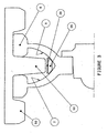
- Figure 1 shows a device 10 to reduce the accumulation of snow, ice, mud, soil and other debris in the idler wheel of a tracked vehicle as installed.
- the device 10 includes an attachment portion 32 and a band portion 30.
- a support 20 is adjustably associated with the tracked vehicle 4 and is provided with holding means 22 located near the idler wheel 6.
- the band portion 30 and the attachment portion 32 are preferably made from a resilient material.
- band portion 30 is made of spring steel while the band portion 40 shown in Figure 2 is made of reinforced rubber.
- the attachment portion 32 is customized to be adjustably secured near the idler wheel by the holding mean 22.
- the band portion 30 freely extends from the attachment portion 32 and at least partially embraces said wheel for remaining in a constant slipping contact or near contact with at least part of the track wheel 6 to reduce the accumulation of snow, ice, mud, soil and other debris on the wheels 6 during a driving condition of the tracked vehicle 4.
- the band portion 30 is fixed to the attachment portion 32 by bolt 36 or other known means.
- Figure 2 illustrates a second embodiment of the device 10 which allows to reduce the accumulation of snow, ice, mud, soil and other debris in the track wheels of tracked vehicles.
- the band portion 40 is integral with the attachment portion 42 and is made of reinforced rubber.
- the band portion 30 has an internal surface 35 generally matching the configuration of the interior portions 7 and 8 of the wheel 6 and an external surface 34 on which snow, ice, mud, soil or other debris may accumulate.
- the internal surface 45 is discontinuous and is made of a plurality of slipper segments 48.
- the slipper segments 48 are preferably made from a low friction material such as UHMW polyethylene.
- a minimum amount of friction be present between the internal surfaces 7 and 8 of wheel 6 and any snow, ice, mud, soil or other debris which may become lodged between the track, the internal surfaces 7 and 8 and the external surface 44 such that such snow, ice, mud, soil or other debris be dislodged as a result of the relative movement of such snow, ice or other debris in relation to the attachment portion 42.
- the internal surface 45 and the slipper elements 48 may assume a variety of forms, lengths and cross-sectional profiles (not shown) as long as they are complementary with the configuration of the internal surfaces 7 and 8 of wheel 6.
- the device 10 may be made from any suitable material well known in the art.
- the band portion 30 of the device 10 effectively prevents any significant accumulation of snow, ice, mud, soil or other debris from between the internal surfaces 7 and 8 of wheel 6 and the track 50.
- Device 10 is bi-directional in the sense that it works effectively in either direction of track wheel rotation, and is extremely simple in design and effective in operation.
Landscapes
- Engineering & Computer Science (AREA)
- Mechanical Engineering (AREA)
- Chemical & Material Sciences (AREA)
- Combustion & Propulsion (AREA)
- Transportation (AREA)
- Soil Working Implements (AREA)
- Vehicle Cleaning, Maintenance, Repair, Refitting, And Outriggers (AREA)
- Cleaning Of Streets, Tracks, Or Beaches (AREA)
- Handcart (AREA)
- Vehicle Body Suspensions (AREA)
- Structure Of Belt Conveyors (AREA)
Claims (12)
- Dispositif (10) destiné à réduire l'accumulation de neige, glace, boue, terre et autres débris dans une roue (6) de véhicules à chenilles (4) du type présentant une partie roue intérieure (8) et une partie roue extérieure (7) définissant un espace ouvert entre elles, ledit dispositif (10) comprenant un support (20) fixé de manière ajustable audit véhicule à chenilles (4) et présentant un moyen d'attache (22) situé à proximité dudit espace,
caractérisé en ce que ledit dispositif (10) comprend en outre une bande (30/40, 32/42) adaptée pour être maintenue en position de manière ajustable par ledit moyen d'attache (22) autour de ladite roue (6) dans ledit espace. - Dispositif selon la revendication 1, dans lequel ladite roue (6) est une roue folle ou une roue dentée.
- Dispositif selon la revendication 2, dans lequel ladite bande (30/40, 32/42) est réalisée en un matériau résilient.
- Dispositif selon la revendication 3, dans lequel ladite bande (40, 42) est réalisée en caoutchouc renforcé.
- Dispositif selon la revendication 3, dans lequel ladite bande (30, 32) est réalisée en acier à ressorts.
- Dispositif (10) destiné à réduire l'accumulation de neige, glace, boue, terre et autres débris dans les roues (6) de véhicules à chenilles (4), ledit dispositif (10) comprenant un support (20) fixé de manière ajustable audit véhicule à chenilles et présentant un moyen d'attache (22) situé à proximité de ladite roue à chenilles (6),
caractérisé en ce que ledit dispositif (10) comprend en outre une bande de présentant une pièce de liaison (32, 42) adaptée pour être maintenue en position de manière ajustable à proximité de la roue (6) par ledit moyen d'attache (22), une pièce formant collier (30, 40) épousant au moins partiellement l'intérieur de ladite roue (6) afin de rester en contact glissant constant ou en contact proche avec au moins une partie dudit intérieur de roue afin de réduire l'accumulation desdits neige, glace, boue, terre et autres débris dans les roues (6) pendant le fonctionnement du véhicule à chenilles, et une partie de liaison reliant de manière ajustable la partie formant collier à la pièce de liaison. - Dispositif selon la revendication 6, dans lequel la partie formant collier (30, 40) présente une surface de contact (35, 45) correspondant généralement à une surface, recevant un crampon de chenille, de la roue (6).
- Dispositif selon l'une quelconque des revendications 6 ou 7, dans lequel la pièce formant collier (30, 40) présente au moins une glissière (48) qui fait saillie vers l'intérieur en direction de la roue à chenilles (6) pour être en contact glissant constant ou en contact proche avec celle-ci.
- Dispositif selon l'une quelconque des revendications 6 à 8, dans lequel la pièce formant collier (30, 40) est réalisée à partir d'un matériau à faible coefficient de frottement.
- Dispositif selon la revendication 6, dans lequel la bande est réalisée à partir d'un matériau résilient.
- Dispositif selon la revendication 7, dans lequel la pièce de liaison (32, 42) est réalisée à partir d'un matériau résilient.
- Dispositif selon l'une quelconque des revendications 7 à 9, dans lequel la pièce formant collier (30, 40) est réalisée à partir d'un matériau résilient.
Applications Claiming Priority (3)
| Application Number | Priority Date | Filing Date | Title |
|---|---|---|---|
| CA 2470553 CA2470553A1 (fr) | 2004-06-09 | 2004-06-09 | Dispositif servant a la reduction de neige et de debris dans les galets de vehicules a chenilles |
| CA2504051A CA2504051C (fr) | 2004-06-09 | 2005-04-11 | Dispositif pour diminuer l'accumulation de neige et d'autres debris dans les roues des vehicules a chenilles |
| PCT/CA2005/000839 WO2005120937A1 (fr) | 2004-06-09 | 2005-06-01 | Dispositif destine a reduire des debris dans les roues de vehicules a chenilles |
Publications (3)
| Publication Number | Publication Date |
|---|---|
| EP1765660A1 EP1765660A1 (fr) | 2007-03-28 |
| EP1765660A4 EP1765660A4 (fr) | 2008-06-18 |
| EP1765660B1 true EP1765660B1 (fr) | 2011-02-16 |
Family
ID=35446888
Family Applications (1)
| Application Number | Title | Priority Date | Filing Date |
|---|---|---|---|
| EP05749836A Active EP1765660B1 (fr) | 2004-06-09 | 2005-06-01 | Dispositif destine a reduire des debris dans les roues de vehicules a chenilles |
Country Status (8)
| Country | Link |
|---|---|
| US (1) | US20050269877A1 (fr) |
| EP (1) | EP1765660B1 (fr) |
| AT (1) | ATE498537T1 (fr) |
| CA (1) | CA2504051C (fr) |
| DE (1) | DE602005026385D1 (fr) |
| DK (1) | DK1765660T3 (fr) |
| NO (1) | NO329552B1 (fr) |
| WO (1) | WO2005120937A1 (fr) |
Families Citing this family (3)
| Publication number | Priority date | Publication date | Assignee | Title |
|---|---|---|---|---|
| US7370918B2 (en) * | 2005-05-31 | 2008-05-13 | Tucker Sno-Cat Corporation | Wheel assembly for a tracked vehicle and anti-accumulation sleeve therefor |
| SE542471C2 (en) * | 2018-07-09 | 2020-05-19 | Bae Systems Haegglunds Ab | Deflector arrangement for a tracked vehicle |
| US11827295B2 (en) | 2020-12-18 | 2023-11-28 | Howe & Howe Inc. | Utilizing a suspension protector to deflect debris away from a set of suspension components of a tracked vehicle |
Family Cites Families (9)
| Publication number | Priority date | Publication date | Assignee | Title |
|---|---|---|---|---|
| US2637603A (en) * | 1951-12-07 | 1953-05-05 | Goodman Mfg Co | Muck stripper for endless track treads |
| US3913943A (en) * | 1974-08-19 | 1975-10-21 | Int Harvester Co | Rock ejecting and suspension limiting arrangement for dual wheeled vehicles |
| US5005922A (en) * | 1987-05-14 | 1991-04-09 | Edwards, Harper, Mcnew & Company | Double V-shaped endless track drive system |
| US4830439A (en) | 1987-10-07 | 1989-05-16 | The United States Of America As Represented By The Secretary Of The Army | Separable scraper bar attachment for track-type vehicles |
| US5226703A (en) | 1992-04-20 | 1993-07-13 | Link-Belt Construction Co. | Idler roller mounting/scraper for track vehicle |
| US5725292A (en) | 1996-06-25 | 1998-03-10 | Caterpillar Inc. | Scraping apparatus for a track idler |
| US5697683A (en) | 1996-12-13 | 1997-12-16 | Caterpillar Inc. | Biased scraping apparatus for an idler |
| US6019443A (en) | 1998-02-02 | 2000-02-01 | Freeman; Ernie | Debris cutter for sprocket drive |
| US20020148065A1 (en) * | 2001-02-26 | 2002-10-17 | Trent Robert J. | Bicycle hub cleaning device |
-
2005
- 2005-04-11 CA CA2504051A patent/CA2504051C/fr active Active
- 2005-06-01 EP EP05749836A patent/EP1765660B1/fr active Active
- 2005-06-01 DE DE602005026385T patent/DE602005026385D1/de active Active
- 2005-06-01 WO PCT/CA2005/000839 patent/WO2005120937A1/fr not_active Application Discontinuation
- 2005-06-01 AT AT05749836T patent/ATE498537T1/de not_active IP Right Cessation
- 2005-06-01 DK DK05749836.2T patent/DK1765660T3/da active
- 2005-06-02 US US11/142,697 patent/US20050269877A1/en not_active Abandoned
-
2006
- 2006-12-29 NO NO20066053A patent/NO329552B1/no unknown
Also Published As
| Publication number | Publication date |
|---|---|
| DK1765660T3 (da) | 2011-05-16 |
| US20050269877A1 (en) | 2005-12-08 |
| EP1765660A4 (fr) | 2008-06-18 |
| NO329552B1 (no) | 2010-11-08 |
| CA2504051C (fr) | 2012-10-02 |
| DE602005026385D1 (de) | 2011-03-31 |
| CA2504051A1 (fr) | 2005-12-09 |
| ATE498537T1 (de) | 2011-03-15 |
| NO20066053L (no) | 2007-03-08 |
| EP1765660A1 (fr) | 2007-03-28 |
| WO2005120937A1 (fr) | 2005-12-22 |
Similar Documents
| Publication | Publication Date | Title |
|---|---|---|
| US7591515B2 (en) | Debris deflecting device | |
| CA2062549C (fr) | Roue motrice pour tracteur sur chenilles | |
| US7832814B2 (en) | Snow and debris deflector for a track system | |
| US4198103A (en) | Differential track assembly for a cable laying machine | |
| EP2949552B1 (fr) | Roue d'entraînement pour une chenille de vehicule de travail. | |
| US20070261898A1 (en) | Traction Assembly for Vehicles and Components Therefor | |
| EP1765660B1 (fr) | Dispositif destine a reduire des debris dans les roues de vehicules a chenilles | |
| EP1786662B1 (fr) | Deflecteur pour neige et debris adapte a un systeme de chenille | |
| WO2003078239A1 (fr) | Chenille en caoutchouc et engin a chenilles en caoutchouc | |
| US8074776B2 (en) | All-terrain vehicle | |
| US6793296B2 (en) | Endless traction band with asymmetrical support | |
| WO1983001234A1 (fr) | Organe racleur-protecteur flexible pour la roue de renvoi d'un assemblage a chenille | |
| CA2470553A1 (fr) | Dispositif servant a la reduction de neige et de debris dans les galets de vehicules a chenilles | |
| US11560189B2 (en) | Track elements for forming a continuous over tyre track with strength enhancement structure | |
| JP2006159966A (ja) | 走行装置および作業機械 | |
| CA2574729A1 (fr) | Ensemble de traction pour vehicules et elements connexes | |
| US2891822A (en) | Track closure | |
| CA2470548A1 (fr) | Deflecteur de neige et de debris pour systeme de chenilles | |
| CA2533344A1 (fr) | Chenille de traction a ergots exterieurs | |
| CA2511866A1 (fr) | Chaine de traction pour bande sans fin de traction et methode d'installation | |
| CA2497011A1 (fr) | Chenille de traction a ergots exterieurs | |
| CA2407015E (fr) | Bande de traction sans fin avec support asymetrique | |
| JPH0453723B2 (fr) | ||
| RU2088436C1 (ru) | Шахтный самоходный вагон | |
| JPS63203485A (ja) | ゴムクロ−ラを用いた作業車両の走行装置 |
Legal Events
| Date | Code | Title | Description |
|---|---|---|---|
| PUAI | Public reference made under article 153(3) epc to a published international application that has entered the european phase |
Free format text: ORIGINAL CODE: 0009012 |
|
| 17P | Request for examination filed |
Effective date: 20061211 |
|
| AK | Designated contracting states |
Kind code of ref document: A1 Designated state(s): AT BE BG CH CY CZ DE DK EE ES FI FR GB GR HU IE IS IT LI LT LU MC NL PL PT RO SE SI SK TR |
|
| DAX | Request for extension of the european patent (deleted) | ||
| A4 | Supplementary search report drawn up and despatched |
Effective date: 20080521 |
|
| 17Q | First examination report despatched |
Effective date: 20090212 |
|
| GRAP | Despatch of communication of intention to grant a patent |
Free format text: ORIGINAL CODE: EPIDOSNIGR1 |
|
| GRAS | Grant fee paid |
Free format text: ORIGINAL CODE: EPIDOSNIGR3 |
|
| GRAA | (expected) grant |
Free format text: ORIGINAL CODE: 0009210 |
|
| AK | Designated contracting states |
Kind code of ref document: B1 Designated state(s): AT BE BG CH CY CZ DE DK EE ES FI FR GB GR HU IE IS IT LI LT LU MC NL PL PT RO SE SI SK TR |
|
| REG | Reference to a national code |
Ref country code: GB Ref legal event code: FG4D |
|
| REG | Reference to a national code |
Ref country code: CH Ref legal event code: EP |
|
| REG | Reference to a national code |
Ref country code: IE Ref legal event code: FG4D |
|
| REF | Corresponds to: |
Ref document number: 602005026385 Country of ref document: DE Date of ref document: 20110331 Kind code of ref document: P |
|
| REG | Reference to a national code |
Ref country code: DE Ref legal event code: R096 Ref document number: 602005026385 Country of ref document: DE Effective date: 20110331 |
|
| REG | Reference to a national code |
Ref country code: SE Ref legal event code: TRGR |
|
| REG | Reference to a national code |
Ref country code: DK Ref legal event code: T3 |
|
| REG | Reference to a national code |
Ref country code: ES Ref legal event code: FG2A Ref document number: 2361158 Country of ref document: ES Kind code of ref document: T3 Effective date: 20110614 |
|
| REG | Reference to a national code |
Ref country code: NL Ref legal event code: VDEP Effective date: 20110216 |
|
| LTIE | Lt: invalidation of european patent or patent extension |
Effective date: 20110216 |
|
| PG25 | Lapsed in a contracting state [announced via postgrant information from national office to epo] |
Ref country code: LT Free format text: LAPSE BECAUSE OF FAILURE TO SUBMIT A TRANSLATION OF THE DESCRIPTION OR TO PAY THE FEE WITHIN THE PRESCRIBED TIME-LIMIT Effective date: 20110216 Ref country code: GR Free format text: LAPSE BECAUSE OF FAILURE TO SUBMIT A TRANSLATION OF THE DESCRIPTION OR TO PAY THE FEE WITHIN THE PRESCRIBED TIME-LIMIT Effective date: 20110517 Ref country code: PT Free format text: LAPSE BECAUSE OF FAILURE TO SUBMIT A TRANSLATION OF THE DESCRIPTION OR TO PAY THE FEE WITHIN THE PRESCRIBED TIME-LIMIT Effective date: 20110616 |
|
| PG25 | Lapsed in a contracting state [announced via postgrant information from national office to epo] |
Ref country code: SI Free format text: LAPSE BECAUSE OF FAILURE TO SUBMIT A TRANSLATION OF THE DESCRIPTION OR TO PAY THE FEE WITHIN THE PRESCRIBED TIME-LIMIT Effective date: 20110216 Ref country code: AT Free format text: LAPSE BECAUSE OF FAILURE TO SUBMIT A TRANSLATION OF THE DESCRIPTION OR TO PAY THE FEE WITHIN THE PRESCRIBED TIME-LIMIT Effective date: 20110216 Ref country code: BG Free format text: LAPSE BECAUSE OF FAILURE TO SUBMIT A TRANSLATION OF THE DESCRIPTION OR TO PAY THE FEE WITHIN THE PRESCRIBED TIME-LIMIT Effective date: 20110516 Ref country code: PL Free format text: LAPSE BECAUSE OF FAILURE TO SUBMIT A TRANSLATION OF THE DESCRIPTION OR TO PAY THE FEE WITHIN THE PRESCRIBED TIME-LIMIT Effective date: 20110216 Ref country code: NL Free format text: LAPSE BECAUSE OF FAILURE TO SUBMIT A TRANSLATION OF THE DESCRIPTION OR TO PAY THE FEE WITHIN THE PRESCRIBED TIME-LIMIT Effective date: 20110216 Ref country code: BE Free format text: LAPSE BECAUSE OF FAILURE TO SUBMIT A TRANSLATION OF THE DESCRIPTION OR TO PAY THE FEE WITHIN THE PRESCRIBED TIME-LIMIT Effective date: 20110216 Ref country code: CY Free format text: LAPSE BECAUSE OF FAILURE TO SUBMIT A TRANSLATION OF THE DESCRIPTION OR TO PAY THE FEE WITHIN THE PRESCRIBED TIME-LIMIT Effective date: 20110216 |
|
| PG25 | Lapsed in a contracting state [announced via postgrant information from national office to epo] |
Ref country code: EE Free format text: LAPSE BECAUSE OF FAILURE TO SUBMIT A TRANSLATION OF THE DESCRIPTION OR TO PAY THE FEE WITHIN THE PRESCRIBED TIME-LIMIT Effective date: 20110216 |
|
| PG25 | Lapsed in a contracting state [announced via postgrant information from national office to epo] |
Ref country code: CZ Free format text: LAPSE BECAUSE OF FAILURE TO SUBMIT A TRANSLATION OF THE DESCRIPTION OR TO PAY THE FEE WITHIN THE PRESCRIBED TIME-LIMIT Effective date: 20110216 Ref country code: RO Free format text: LAPSE BECAUSE OF FAILURE TO SUBMIT A TRANSLATION OF THE DESCRIPTION OR TO PAY THE FEE WITHIN THE PRESCRIBED TIME-LIMIT Effective date: 20110216 Ref country code: SK Free format text: LAPSE BECAUSE OF FAILURE TO SUBMIT A TRANSLATION OF THE DESCRIPTION OR TO PAY THE FEE WITHIN THE PRESCRIBED TIME-LIMIT Effective date: 20110216 |
|
| PLBE | No opposition filed within time limit |
Free format text: ORIGINAL CODE: 0009261 |
|
| STAA | Information on the status of an ep patent application or granted ep patent |
Free format text: STATUS: NO OPPOSITION FILED WITHIN TIME LIMIT |
|
| 26N | No opposition filed |
Effective date: 20111117 |
|
| REG | Reference to a national code |
Ref country code: CH Ref legal event code: PL |
|
| REG | Reference to a national code |
Ref country code: DE Ref legal event code: R097 Ref document number: 602005026385 Country of ref document: DE Effective date: 20111117 |
|
| REG | Reference to a national code |
Ref country code: IE Ref legal event code: MM4A |
|
| PG25 | Lapsed in a contracting state [announced via postgrant information from national office to epo] |
Ref country code: IE Free format text: LAPSE BECAUSE OF NON-PAYMENT OF DUE FEES Effective date: 20110601 Ref country code: CH Free format text: LAPSE BECAUSE OF NON-PAYMENT OF DUE FEES Effective date: 20110630 Ref country code: LI Free format text: LAPSE BECAUSE OF NON-PAYMENT OF DUE FEES Effective date: 20110630 |
|
| PG25 | Lapsed in a contracting state [announced via postgrant information from national office to epo] |
Ref country code: MC Free format text: LAPSE BECAUSE OF NON-PAYMENT OF DUE FEES Effective date: 20110630 |
|
| PG25 | Lapsed in a contracting state [announced via postgrant information from national office to epo] |
Ref country code: LU Free format text: LAPSE BECAUSE OF NON-PAYMENT OF DUE FEES Effective date: 20110601 |
|
| PG25 | Lapsed in a contracting state [announced via postgrant information from national office to epo] |
Ref country code: IS Free format text: LAPSE BECAUSE OF FAILURE TO SUBMIT A TRANSLATION OF THE DESCRIPTION OR TO PAY THE FEE WITHIN THE PRESCRIBED TIME-LIMIT Effective date: 20110216 |
|
| PG25 | Lapsed in a contracting state [announced via postgrant information from national office to epo] |
Ref country code: TR Free format text: LAPSE BECAUSE OF FAILURE TO SUBMIT A TRANSLATION OF THE DESCRIPTION OR TO PAY THE FEE WITHIN THE PRESCRIBED TIME-LIMIT Effective date: 20110216 |
|
| PG25 | Lapsed in a contracting state [announced via postgrant information from national office to epo] |
Ref country code: HU Free format text: LAPSE BECAUSE OF FAILURE TO SUBMIT A TRANSLATION OF THE DESCRIPTION OR TO PAY THE FEE WITHIN THE PRESCRIBED TIME-LIMIT Effective date: 20110216 |
|
| REG | Reference to a national code |
Ref country code: FR Ref legal event code: PLFP Year of fee payment: 12 |
|
| REG | Reference to a national code |
Ref country code: FR Ref legal event code: PLFP Year of fee payment: 13 |
|
| REG | Reference to a national code |
Ref country code: FR Ref legal event code: PLFP Year of fee payment: 14 |
|
| REG | Reference to a national code |
Ref country code: FR Ref legal event code: PLFP Year of fee payment: 19 |
|
| P01 | Opt-out of the competence of the unified patent court (upc) registered |
Effective date: 20230513 |
|
| PGFP | Annual fee paid to national office [announced via postgrant information from national office to epo] |
Ref country code: ES Payment date: 20230707 Year of fee payment: 19 |
|
| PGFP | Annual fee paid to national office [announced via postgrant information from national office to epo] |
Ref country code: FR Payment date: 20240328 Year of fee payment: 20 |
|
| PGFP | Annual fee paid to national office [announced via postgrant information from national office to epo] |
Ref country code: GB Payment date: 20240402 Year of fee payment: 20 |
|
| PGFP | Annual fee paid to national office [announced via postgrant information from national office to epo] |
Ref country code: DE Payment date: 20240328 Year of fee payment: 20 |
|
| PGFP | Annual fee paid to national office [announced via postgrant information from national office to epo] |
Ref country code: DK Payment date: 20240612 Year of fee payment: 20 |
|
| PGFP | Annual fee paid to national office [announced via postgrant information from national office to epo] |
Ref country code: IT Payment date: 20240513 Year of fee payment: 20 Ref country code: FI Payment date: 20240612 Year of fee payment: 20 |
|
| PGFP | Annual fee paid to national office [announced via postgrant information from national office to epo] |
Ref country code: SE Payment date: 20240328 Year of fee payment: 20 |