EP1764556A2 - Wärmespeicherkamin - Google Patents
Wärmespeicherkamin Download PDFInfo
- Publication number
- EP1764556A2 EP1764556A2 EP20060396016 EP06396016A EP1764556A2 EP 1764556 A2 EP1764556 A2 EP 1764556A2 EP 20060396016 EP20060396016 EP 20060396016 EP 06396016 A EP06396016 A EP 06396016A EP 1764556 A2 EP1764556 A2 EP 1764556A2
- Authority
- EP
- European Patent Office
- Prior art keywords
- heat
- fireplace
- storing
- storage means
- heat storage
- Prior art date
- Legal status (The legal status is an assumption and is not a legal conclusion. Google has not performed a legal analysis and makes no representation as to the accuracy of the status listed.)
- Withdrawn
Links
- 238000005338 heat storage Methods 0.000 claims abstract description 79
- 239000003546 flue gas Substances 0.000 claims abstract description 31
- 239000000779 smoke Substances 0.000 claims abstract description 28
- UGFAIRIUMAVXCW-UHFFFAOYSA-N Carbon monoxide Chemical compound [O+]#[C-] UGFAIRIUMAVXCW-UHFFFAOYSA-N 0.000 claims abstract description 11
- 239000000463 material Substances 0.000 claims abstract description 11
- 239000007789 gas Substances 0.000 claims abstract description 4
- 238000009413 insulation Methods 0.000 claims description 24
- 230000005855 radiation Effects 0.000 claims description 4
- 239000004020 conductor Substances 0.000 claims description 3
- 230000000694 effects Effects 0.000 claims description 3
- 238000010438 heat treatment Methods 0.000 description 19
- 239000012212 insulator Substances 0.000 description 7
- 230000000717 retained effect Effects 0.000 description 7
- 239000004575 stone Substances 0.000 description 5
- 239000000919 ceramic Substances 0.000 description 3
- 230000001965 increasing effect Effects 0.000 description 3
- 238000002835 absorbance Methods 0.000 description 2
- 230000002708 enhancing effect Effects 0.000 description 2
- 239000011810 insulating material Substances 0.000 description 2
- 238000000465 moulding Methods 0.000 description 2
- 229910001018 Cast iron Inorganic materials 0.000 description 1
- 229910000831 Steel Inorganic materials 0.000 description 1
- 229910045601 alloy Inorganic materials 0.000 description 1
- 239000000956 alloy Substances 0.000 description 1
- 238000005266 casting Methods 0.000 description 1
- 238000003776 cleavage reaction Methods 0.000 description 1
- 238000005034 decoration Methods 0.000 description 1
- 230000003111 delayed effect Effects 0.000 description 1
- 238000005485 electric heating Methods 0.000 description 1
- 230000009931 harmful effect Effects 0.000 description 1
- 230000005923 long-lasting effect Effects 0.000 description 1
- 238000000034 method Methods 0.000 description 1
- 239000011490 mineral wool Substances 0.000 description 1
- 238000012986 modification Methods 0.000 description 1
- 230000004048 modification Effects 0.000 description 1
- 230000001105 regulatory effect Effects 0.000 description 1
- 230000000630 rising effect Effects 0.000 description 1
- 230000007017 scission Effects 0.000 description 1
- 230000002269 spontaneous effect Effects 0.000 description 1
- 239000010959 steel Substances 0.000 description 1
- 239000002023 wood Substances 0.000 description 1
Images


Classifications
-
- F—MECHANICAL ENGINEERING; LIGHTING; HEATING; WEAPONS; BLASTING
- F24—HEATING; RANGES; VENTILATING
- F24B—DOMESTIC STOVES OR RANGES FOR SOLID FUELS; IMPLEMENTS FOR USE IN CONNECTION WITH STOVES OR RANGES
- F24B1/00—Stoves or ranges
- F24B1/20—Ranges
- F24B1/24—Ranges with built-in masses for heat storage or heat insulation
-
- F—MECHANICAL ENGINEERING; LIGHTING; HEATING; WEAPONS; BLASTING
- F24—HEATING; RANGES; VENTILATING
- F24B—DOMESTIC STOVES OR RANGES FOR SOLID FUELS; IMPLEMENTS FOR USE IN CONNECTION WITH STOVES OR RANGES
- F24B1/00—Stoves or ranges
- F24B1/18—Stoves with open fires, e.g. fireplaces
Definitions
- the present invention relates to a heat-storing fireplace as defined in the preamble of claim
- One specific objective of the invention is to disclose a new type of heat-storing fireplace that fully automatically and spontaneously, without any adjustment measures from outside, as well as without any spontaneous mechanical adjustment measures within the stove, releases heat as long and uniformly as possible.
- One further objective of the invention is to disclose a heat-storing fireplace that fast and effectively absorbs the hot heats of flue gases at one relatively fast heating step, but still releases the heat gradually and periodically, uniformly over a long period of time.
- the heat-storing fireplace in accordance with the invention is characterized by what has been presented in claim 1.
- the heat-storing fireplace in accordance with the invention includes an outer jacket and an inner jacket of a heat-storing material, the inner jacket having a fire chamber provided with a grate, as well as a smoke channel consisting of a heat-storing material for recovering the heat contained in the hot flue gas flow from the fire chamber and for conveying the gases into a flue.
- a heat storage means arranged within the heat-storing smoke channel, along its given length, is a heat storage means, which substantially increases the heat storage capacity of the given length of the smoke channel.
- the heat storage means is equipped at its circumference with a heat insulation layer for delaying the heat flows from the heat storage means to the outer jacket; that is, for limiting heat flows in a perpendicular direction with respect to the flow of flue gases.
- the fireplace has a big heat storage capacity; it can fast and effectively absorb the heat contained in hot flue gases, but still, as a novel and surprising feature, because of the inventive structure, it releases heat to the outer jacket and via it into the space being heated uniformly, long, and the designed amount at a time.
- the invention is based on gradual or zoned heat release so that as the heat is absorbed simultaneously in the different heat-storing masses of the fireplace, these masses release the heat at different times and suitably arranged consecutively, so that the total heat release output of the entire fireplace remains substantially steady for as long a period as possible.
- the heat storage means placed in the flue gas flow includes several adjacent heat-storing tiles at a suitable distance from one another, this distance, i.e. a suitable gap, forming flow paths for the flue gases.
- the tiles are preferably disposed in a vertical direction so that the flue gases flow from under upwards between the tiles. It is also possible to place the tiles in a horizontal direction, or at an oblique angle, with respect to the flue gas flow, at a distance from one another.
- the tiles can also constitute one integral structure, or especially in some very hot conditions, the tile can consist of several sub-elements that together form one tile of the heat storage means.
- the heat-storing tiles have a thickness that is at least as big as the distance between them, i.e. the thickness of the smoke channel formed between them.
- the heat storage means consists either wholly or partly of some other material having suitable heat storage properties, such as of steel, cast iron or ceramic casting alloys.
- the tiles are of different thickness and/or the gaps between the tiles are of different width, depending on the desired heat storage properties, the flow amounts of the gas flows directed to the heat storage means, the flow directions, and the temperature, as well as on the structure of the entire fireplace.
- the heat insulation layer surrounding the heat storage means is used to limit and regulate the flow of heat out of the heat storage means. It can even surround the heat storage means from every side so that only the flue gases are left sufficient flow paths within the heat storage means and out of it.
- a suitable insulator is e.g. a hard mineral wool tile or a ceramic insulation tile.
- the heat insulation layers on the outer surface of the heat storage means, or outer at its circumference have a substantially higher insulation capacity than the insulation tile. In this manner, it is guaranteed that the heat accumulated in the heat-storing mass surrounding the fire chamber is emitted into the space to be heated substantially entirely before the heat contained in the heat storage means is conveyed to the outer jacket of the fireplace, through it, and into the space to be heated.
- an insulated heat storage means takes advantage of the cleavage plane of soapstone.
- the soapstone tiles are placed into the heat storage means so that the heat storage means receives the heat contained in the flue gases as effectively as possible, but also releases heat towards the outer jacket of the fireplace as slowly as possible.
- the heat transfer from the heat storage means into the heat-storing structures of the fire chamber can be further regulated and delayed by isolating the heat-storing masses of the fire chamber and those of the heat storage means from a direct heat transfer contact with one another by means of horizontal, vertical and/or oblique heat limiters.
- a suitable insulation tile can act as the heat limiter, the thickness of which insulation tile is selected to be suitable for each case specifically.
- the heat absorbed by the heat storage means can be made transfer practically entirely in a perpendicular direction with respect to the direction of flow of flue gases, generally in a horizontal direction, and with a delay determined by the heat insulator with respect to the heating process.
- the heat can be made radiate downwards from the heat storage means into the fire chamber and out via it, e.g. via the fire door, whereby the impression is similar to a situation where the fire is lit in an oven.
- the fire chamber is reduced to form a throat before the smoke channel.
- the heat storage means of the invention is placed into the smoke channel on top of the fire chamber, it is preferable that immediately after the throat, the smoke channel includes an open flow space before the heat storage means. This suitable distance between a fire and a heat storage means ensures that the heat radiation being emitted from a red-hot heat storage means does not have a harmful effect on the burning in the fire chamber.
- the heat storage means that retains heat and releases it gradually can be implemented in several different types of fireplaces.
- the fireplace can be a top-flue connection fireplace where the flue gases rise directly upwards from the fire chamber and escape into the flue from the top portion of the fireplace.
- the fireplace can be a bottom-connection fireplace provided with side channels, wherein the flue gases circulate upwards from the fire chamber and further downwards along the side channels of the edges of the fireplace, escaping from the fireplace into the flue in the bottom portion of the fireplace.
- the heat storage means of the invention is preferably disposed above the fire chamber and at a suitable distance from it.
- the heat storage means is disposed farther in the flue gas flow, or that it extends farther into the flue gas flow, even downwards the side channels.
- a second heat storage means of the invention which recovers the heat contained in the flue gases, and which further, thanks to suitable insulation arrangements, releases the heat outside the fireplace later than before.
- the heat-storing fireplace in which the invention is used can also be a baking oven.
- the heat storage means can be disposed above the oven space for enhancing the heat absorbance in the oven roof, keeping it longer in a baking temperature.
- the heat storage means can also be placed underneath the oven space, where conventionally, there is just the ash bin, and thus space even for a big additional heat storage means and for a limiter of heat flow arranged about its circumference.
- a conventional baking oven can be arranged so as to be a heat source that retains heat well and releases it long and uniformly, thereby also improving the baking properties of the oven.
- the heat-storing and heat-conducting outer jacket of the fireplace is divided into two or more zones using a suitable heat-insulating or weakly heat-conductive material.
- These zones of the outer jacket function as surfaces that release heat in different ways, depending on the heat flows within the outer jacket, because due to the effect of an insulating material, there are no significant heat flows between the zones. It is even possible that using the heat storage means and heat insulators in accordance with the invention, substantially all the heat accumulated in the fireplace can be made release via a given limited zone of the outer surface. This makes it possible to limit an instantaneous heat flow i.e. heating capacity, and the accumulated amount of heat can be made last longer than before.
- the heat-storing fireplace of the invention has significant advantages over prior art.
- Using an additional heat storage means in accordance with the invention the heat contained in the flue gases can be effectively recovered, and a heat amount bigger than conventionally can be made accumulate in the fireplace.
- the outer jacket of the fireplace does not get too hot, and, in practice, compared to a similar conventional fireplace, the outer jacket can remain even cooler. In this manner, the nominal heat output can be adjusted to suit also low-energy houses.
- the structure of the invention is also very flexible in terms of its structural solution alternatives, enabling its placing in heat-storing fireplaces into nearly any suitable place in the flue gas flow, and thus substantially into all heat-storing fireplaces of a different model or shape.
- the fireplace of the invention that releases heat gradually keeps the surrounding space to be heated substantially standard-warm through the entire heating period, which depending on the size of the heat-storing masses of the entire fireplace, can be several days.
- a substantial feature in the invention is that during the long and uniform heat release period, there is no need to make any adjustments in the fireplace.
- the fireplace does not have any spontaneously moving adjustment structures, but the uniform and long heat release has been implemented using fixed and permanent structures.
- the fireplace as shown in Fig. 1 includes an outer jacket 1 and an inner jacket 2, both being of a material that retains heat well.
- the inner jacket forms an ash bin 3, on top of which there is a grate 4; as well as a fire chamber 5; a throat 6 disposed in the upper part of the fire chamber and an upwards directed smoke channel 7, which leads the flue gases into a flue connection 8.
- the aforementioned parts are preferably of soapstone, but other materials can also be used.
- a heat storage means 9 Arranged in the smoke channel 7, along its entire depth and width, is a heat storage means 9; that is, a number of soapstone tiles 10, which can be tiles consisting of one stone or of more than one element. There are, for example, 3 to 10 tiles side by side in a vertical direction at a distance from one another, so that vertical, equally thick gaps are formed between the tiles that form the smoke channels for the flue gas flow.
- a heat insulation layer 11 functioning as a limiter of heat flows.
- a heat limiter 12 arranged in the lower edge of the smoke channel 7 and the heat storage means 9 is a heat limiter 12, so that the soapstone structures disposed above and underneath it are not in a good, direct heat conduction contact with one another.
- heat is retained in the structures of the fire chamber 5, the throat 6, the walls of the free flow space 13, and the heat storage means 9 before the flue gases escape into the flue 8.
- the heat entering the space being heated consists mainly of radiation heat that enters through the fire door.
- the heat retained in the structures of the fire chamber and the throat is conducted and radiates into the outer jacket 1 and further from it into the space to be heated.
- the heat storage means does not release the heat immediately into the outer jacket 1; instead it uses a suitable oven-specific time constant to be selected separately, the time constant being affected first of all by the properties of the heat-insulating materials to be used. In this manner, by suitable selections, the heat is made release from the heat storage means into the outer jacket 1 only when the main part of the heat retained up to the level of the fire chamber has already heated the surrounding room space.
- FIG. 2 shows a bottom-flue connection fireplace having an outer jacket 1 and inner jacket 2 of a heat-storing material, side channels 14 between them, as well as double stones 15 in the outer surfaces of the side channels for enhancing the heat storage capacity of the fireplace.
- the inner jacket 2 includes an ash bin 3, a grate 4, a fire chamber 5, a throat 6, a free flow space 13 above the throat, as well as an upwards directed smoke channel 7. Beneath the transversal upper lid 16 the smoke channel turns downwards into the side channels 14, the side channels being connected underneath and behind the smoke channel into a common flue connection in a manner known per se.
- a heat storage means 9 Arranged within the smoke channel, supported by the walls 7 of the smoke channels, is a heat storage means 9; that is, a whole consisting of several vertical e.g. soapstone tiles, wherein the flue gases are allowed to rise between the tiles and release heat to the stones.
- the heat storage means 9 is isolated from the structures of the smoke channel 7 by means of an insulation layer 11, and in addition, the structure of the smoke channel that retains and conducts heat is isolated by a horizontal heat limiter 12 in the area of the free flow space 13.
- the structures of the fire chamber 5, the smoke channel 7, the heat storage means 9 and the double stones of the side channels become very hot.
- the retained heat is conducted and radiates first from the area of the fire chamber 5 into the outer jacket 1 and due to the effect of the decorative moldings 18, mainly from the outer jacket middle area between them, into the room space.
- the heat retained in the heat storage means 9 is not allowed to emit into the outer jacket through the insulators. In this manner, the upper part of the fireplace does not heat the room space until the heat of the lower part has been consumed.
- the insulation thickness of the upper part can be increased so that most of the heat is not allowed to enter the upper part of the outer jacket, but its only flow path is downwards after the structures surrounding the fireplace have sufficiently cooled.
- the fireplace can be made release heat in steps a, b and c that are performed consecutively with respect of time and from different heights from the outer jacket, or in the second embodiment, in heat flows A, B and C that are consecutive both with respect to time and place from the height of the fire chamber.
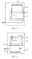
- Fig. 3 schematically shows a baking oven in which the heat storage means 20 is placed on top of the oven space 21, the tiles of the heat storage means being fixed to the oven roof 22.
- the heat storage means is provided with an effective insulation layer 23 on the top and sides thereof. In this manner, the heat storage means enhances the absorbance of heat in the oven roof, thus keeping it longer in a baking temperature.
- Fig. 4 shows a second embodiment of a baking oven, according to the invention, wherein the flue gases escaping from the oven space 21 conventionally circulate on top of the oven roof 22 forwards and downwards from the sides.
- a heat storage means 25 arranged beneath the oven space is a heat storage means 25 provided with an insulation layer 24 on the sides and top, through which insulation layer the flue gases travel towards the flue connection.
Landscapes
- Engineering & Computer Science (AREA)
- Chemical & Material Sciences (AREA)
- Combustion & Propulsion (AREA)
- Mechanical Engineering (AREA)
- General Engineering & Computer Science (AREA)
- Electric Stoves And Ranges (AREA)
Applications Claiming Priority (1)
| Application Number | Priority Date | Filing Date | Title |
|---|---|---|---|
| FI20050920A FI20050920A0 (fi) | 2005-09-15 | 2005-09-15 | Varaava tulisija |
Publications (1)
| Publication Number | Publication Date |
|---|---|
| EP1764556A2 true EP1764556A2 (de) | 2007-03-21 |
Family
ID=35151379
Family Applications (1)
| Application Number | Title | Priority Date | Filing Date |
|---|---|---|---|
| EP20060396016 Withdrawn EP1764556A2 (de) | 2005-09-15 | 2006-09-15 | Wärmespeicherkamin |
Country Status (2)
| Country | Link |
|---|---|
| EP (1) | EP1764556A2 (de) |
| FI (1) | FI20050920A0 (de) |
Cited By (3)
| Publication number | Priority date | Publication date | Assignee | Title |
|---|---|---|---|---|
| EP2457026A4 (de) * | 2009-07-22 | 2018-03-07 | Mika Tapio Reijonen | Wärmespeichernder kamin |
| RU2701097C1 (ru) * | 2019-01-17 | 2019-09-24 | Полина Андреевна Савченко | Устройство для обогрева |
| RU202006U1 (ru) * | 2020-08-07 | 2021-01-27 | Андрей Дмитриевич Кондратенко | Банная печь-каменка |
-
2005
- 2005-09-15 FI FI20050920A patent/FI20050920A0/fi not_active Application Discontinuation
-
2006
- 2006-09-15 EP EP20060396016 patent/EP1764556A2/de not_active Withdrawn
Cited By (3)
| Publication number | Priority date | Publication date | Assignee | Title |
|---|---|---|---|---|
| EP2457026A4 (de) * | 2009-07-22 | 2018-03-07 | Mika Tapio Reijonen | Wärmespeichernder kamin |
| RU2701097C1 (ru) * | 2019-01-17 | 2019-09-24 | Полина Андреевна Савченко | Устройство для обогрева |
| RU202006U1 (ru) * | 2020-08-07 | 2021-01-27 | Андрей Дмитриевич Кондратенко | Банная печь-каменка |
Also Published As
| Publication number | Publication date |
|---|---|
| FI20050920A0 (fi) | 2005-09-15 |
Similar Documents
| Publication | Publication Date | Title |
|---|---|---|
| US4230092A (en) | Method and apparatus for improvements in convective heating | |
| WO2000050817A1 (en) | Fireplace insert | |
| US20140299117A1 (en) | Very shallow heating apparatus with very high yield and a wide view | |
| JP2013078286A (ja) | 燃料からの熱エネルギーと、ドーム型の天井による輻射熱エネルギーを有効利用し、石窯内の温度を調節しながら長時間連続使用可能な、オーブン調理のほか、ダッチオーブン調理器、燻製器としての機能も有する石窯 | |
| RU132871U1 (ru) | Печь | |
| EP0806142B1 (de) | Backofen | |
| US4681087A (en) | Woodkiln combustion device | |
| CA2025087C (en) | Fireplace construction | |
| EP0687351B1 (de) | Heizvorrichtung mit festen brennstoffen | |
| RU2547853C2 (ru) | Камин | |
| EP1376014B1 (de) | Ofen nach Art eines Kamins | |
| DE102004011017B4 (de) | Grundofen | |
| RU2038540C1 (ru) | Физиотерапевтическое устройство каминного типа | |
| FI119077B (fi) | Tulisija | |
| RU95799U1 (ru) | Печь для бани | |
| KR100201047B1 (ko) | 벽난로 | |
| FI105948B (fi) | Varaava tulisija | |
| RU2818956C2 (ru) | Отопительное устройство | |
| EA039649B1 (ru) | Банная печь | |
| RU2774457C1 (ru) | Печь для приготовления пищи на открытом воздухе | |
| RU2701097C1 (ru) | Устройство для обогрева | |
| RU2792953C2 (ru) | Способ сжигания твердого топлива в бытовом твердотопливном отопительном устройстве с помощью колосниковой решетки и колосниковая решетка для осуществления этого способа | |
| US1637659A (en) | Thermoelectric oven | |
| FI127706B (fi) | Laite tulisijaa varten polttoaineen polttamiseksi, sovitelma tulisijassa polttoaineen polttamiseksi, tulisija ja menetelmä polttoaineen polttamiseksi tulisijassa | |
| FR2528153A1 (fr) | Four de cuisson pour produits alimentaires |
Legal Events
| Date | Code | Title | Description |
|---|---|---|---|
| PUAI | Public reference made under article 153(3) epc to a published international application that has entered the european phase |
Free format text: ORIGINAL CODE: 0009012 |
|
| AK | Designated contracting states |
Kind code of ref document: A2 Designated state(s): AT BE BG CH CY CZ DE DK EE ES FI FR GB GR HU IE IS IT LI LT LU LV MC NL PL PT RO SE SI SK TR |
|
| AX | Request for extension of the european patent |
Extension state: AL BA HR MK YU |
|
| RAP1 | Party data changed (applicant data changed or rights of an application transferred) |
Owner name: NUNNAUUNI OY |
|
| STAA | Information on the status of an ep patent application or granted ep patent |
Free format text: STATUS: THE APPLICATION IS DEEMED TO BE WITHDRAWN |
|
| 18D | Application deemed to be withdrawn |
Effective date: 20110401 |