EP1764553A1 - Brûleur à prémélange à stabilité élevée pour turbine a gaz - Google Patents
Brûleur à prémélange à stabilité élevée pour turbine a gaz Download PDFInfo
- Publication number
- EP1764553A1 EP1764553A1 EP05425639A EP05425639A EP1764553A1 EP 1764553 A1 EP1764553 A1 EP 1764553A1 EP 05425639 A EP05425639 A EP 05425639A EP 05425639 A EP05425639 A EP 05425639A EP 1764553 A1 EP1764553 A1 EP 1764553A1
- Authority
- EP
- European Patent Office
- Prior art keywords
- burner
- premix
- swirler
- outlet
- discharge throat
- Prior art date
- Legal status (The legal status is an assumption and is not a legal conclusion. Google has not performed a legal analysis and makes no representation as to the accuracy of the status listed.)
- Withdrawn
Links
Images


Classifications
-
- F—MECHANICAL ENGINEERING; LIGHTING; HEATING; WEAPONS; BLASTING
- F23—COMBUSTION APPARATUS; COMBUSTION PROCESSES
- F23R—GENERATING COMBUSTION PRODUCTS OF HIGH PRESSURE OR HIGH VELOCITY, e.g. GAS-TURBINE COMBUSTION CHAMBERS
- F23R3/00—Continuous combustion chambers using liquid or gaseous fuel
- F23R3/28—Continuous combustion chambers using liquid or gaseous fuel characterised by the fuel supply
- F23R3/286—Continuous combustion chambers using liquid or gaseous fuel characterised by the fuel supply having fuel-air premixing devices
-
- F—MECHANICAL ENGINEERING; LIGHTING; HEATING; WEAPONS; BLASTING
- F23—COMBUSTION APPARATUS; COMBUSTION PROCESSES
- F23R—GENERATING COMBUSTION PRODUCTS OF HIGH PRESSURE OR HIGH VELOCITY, e.g. GAS-TURBINE COMBUSTION CHAMBERS
- F23R3/00—Continuous combustion chambers using liquid or gaseous fuel
- F23R3/02—Continuous combustion chambers using liquid or gaseous fuel characterised by the air-flow or gas-flow configuration
- F23R3/04—Air inlet arrangements
- F23R3/10—Air inlet arrangements for primary air
- F23R3/12—Air inlet arrangements for primary air inducing a vortex
- F23R3/14—Air inlet arrangements for primary air inducing a vortex by using swirl vanes
-
- F—MECHANICAL ENGINEERING; LIGHTING; HEATING; WEAPONS; BLASTING
- F23—COMBUSTION APPARATUS; COMBUSTION PROCESSES
- F23R—GENERATING COMBUSTION PRODUCTS OF HIGH PRESSURE OR HIGH VELOCITY, e.g. GAS-TURBINE COMBUSTION CHAMBERS
- F23R3/00—Continuous combustion chambers using liquid or gaseous fuel
- F23R3/28—Continuous combustion chambers using liquid or gaseous fuel characterised by the fuel supply
- F23R3/34—Feeding into different combustion zones
- F23R3/343—Pilot flames, i.e. fuel nozzles or injectors using only a very small proportion of the total fuel to insure continuous combustion
-
- F—MECHANICAL ENGINEERING; LIGHTING; HEATING; WEAPONS; BLASTING
- F23—COMBUSTION APPARATUS; COMBUSTION PROCESSES
- F23D—BURNERS
- F23D2204/00—Burners adapted for simultaneous or alternative combustion having more than one fuel supply
- F23D2204/10—Burners adapted for simultaneous or alternative combustion having more than one fuel supply gaseous and liquid fuel
-
- F—MECHANICAL ENGINEERING; LIGHTING; HEATING; WEAPONS; BLASTING
- F23—COMBUSTION APPARATUS; COMBUSTION PROCESSES
- F23D—BURNERS
- F23D2900/00—Special features of, or arrangements for burners using fluid fuels or solid fuels suspended in a carrier gas
- F23D2900/00015—Pilot burners specially adapted for low load or transient conditions, e.g. for increasing stability
Definitions
- the present invention relates generally to gas turbines for power generation and more particularly to a high-stability premix burner for installation in such machines.
- the gas turbine machines in current use are frequently equipped with Dry Low NOx (DLN) burners, as in the case of the SW V94.3A2 gas turbine machine, for instance, which is installed in a number of combined cycle plants of the Applicant.
- DNL Dry Low NOx
- CBO Cylindrical Burner Outlet
- the main part of the flame in this type of combustor is obtained by premixing air with the fuel before it is delivered to the combustion chamber, using "lean" combustion mixtures.
- the premixed flame is supported by a diffusion pilot flame.
- the burner includes two coaxial swirlers, one axial and the other diagonal, a fuel oil lance and a metal grid placed over the diagonal swirler inlet.
- the gas is delivered to the combustion chamber along three lines (premix, pilot and diffusion).
- the diffusion gas is only used in the ignition stage; in normal operation the fuel is distributed between the pilot and premix lines in a ratio that varies according to the load.
- the diagonal swirler has a truncated cone-shaped section and is complete with blades (e.g. 20 in the case of the above-mentioned burner) slightly inclined with respect to the outflow direction. Over 90%, in particular about 92%, of the air delivered to the burner as a whole passes through the diagonal swirler.
- the premix gas is delivered through an annular manifold that serves small ducts formed inside the blades on the diagonal swirler; in a particular embodiment, each of these ducts leads to 9 gas nozzles, 4 on the extrados and 5 on the intrados of each diagonal swirler blade.
- the axial swirler is a relatively narrow duct, complete with a number of blades (e.g. 8) lying at a steep angle to the direction of the flow of air, and ending at the oil lance placed inside the swirler.
- This component feeds a diffusion flame that can be produced by injecting the gas from so-called “diffusion nozzles” and/or “pilot nozzles”.
- the gas diffusion nozzles are situated upstream of the axial swirler. They consist of a number of small holes (e.g. 24 holes 3.5 mm in diameter) arranged symmetrically around the circumference in groups of three.
- the igniter is installed in the section where the diffusion nozzles inject the fuel.
- the "pilot gas” nozzles are also located upstream of the axial swirler, but slightly downstream of the igniter; they consist, for instance, of four holes 4.8 mm in diameter lying at right angles to one another.
- the oil lance is positioned inside the axial swirler, ends at about the swirler blades and has a nozzle at the end that extends into the combustion chamber to deliver fuel oil.
- the oil lance is replaced by a so-called "dummy" lance, which has no effect whatsoever on the combustion process.
- the perforated metal grid is situated at the diagonal swirler inlet and serves the purpose of making the flow delivered to the burner more uniform, eliminating any turbulence.
- the CBO which is installed in the majority of combustors installed in such machines, was introduced by Siemens with a view to modifying the fluid-dynamic field at the burner outlet. This component changes the time lag between the fuel inlet and the air-fuel mixture ignition, thereby improving the stability conditions of the burner.
- oscillations occur as a result of interaction between the heat released by the flame and the acoustics of the combustion chamber: fluctuations in the amount of heat released by the flame excite the acoustic field of the pressures in the combustor which, in turn, triggers further fluctuations in the release of heat. If the fluctuations in the pressure and the heat released are in a favorable phase relationship, the oscillations that are generated are self-supporting and become amplified up to a limit cycle determined by the non-linearity of the system. Under certain circumstances, the forces generated by the pressure oscillations can reach amplitudes that reduce the average life and performance of the combustor. Preventing or reducing combustion instability is one of the priorities in the conduction of gas turbines equipped with high energy density combustors.
- the combustion process control system monitors the values recorded by sensors capable of measuring the machine mechanical oscillations and thus manages the different critical conditions that can occur with respect to preset system thresholds.
- the safety devices are enabled 55 seconds after reaching a velocity of 47 Hz or 2820 rpm and they are activated when the signals coming from the acceleration sensors (accelerometers) positioned just outside the combustion chamber reach the following acceleration values:
- Tripping involves the immediate shutdown of the gas turbine due to the enabling of a safety device by the control system.
- Analyses conducted on the Applicant's SW V94.3A2 gas turbine machines demonstrated that these trips occur as a result the third limit being exceeded and always under full load in steady state operating conditions.
- the object of the present invention is to provide a premix burner for gas turbines that is highly stable in operation so as to enable a wider use of gas turbine machines which are characterized by instability problems in operation at high and medium loads.
- a particular object of the present invention is to provide a burner of the above-mentioned type suitable for installation in Siemens gas turbine machines of the VX4 series, such as the SW V94.3A2.
- Another object of the present invention is to provide a burner of the above-mentioned type that can be installed in gas turbine machines in the place of the original burner without needing any structural adaptation, and that demands no changes to the system and machine modulation logic for its operation.
- the burner comprises a main tubular body 1 from which a flange 2, in an intermediate position, extends radially to connect the body 1 to a wall 3 of the outer casing of the gas turbine (not shown).
- An oil lance 4 shown only partially in figure 1 and inactive in the event of gas firing, is installed coaxially in the tubular body 1 and defines an annular duct 5 for the diffusion gas together with the inner wall of said tubular body 1.
- the premix gas is delivered through nozzles 7a to a diagonal swirler 8 with a truncated cone-shaped cross-section and equipped with blades lying at a slight angle to the outflow direction.
- the diagonal swirler 8 is situated inside an annular duct 9 for the premix flow, through which more than 90% of the combustion air flows.
- the premix gas is delivered through small ducts formed inside the blades of the diagonal swirler 8, which in turn serve groups of nozzles positioned on the extrados and intrados of each blade of the diagonal swirler 8.
- an annular chamber 11 On the outside of the end portion of the tubular body 1 there is an annular chamber 11, through which the pilot air is fed to an axial swirler 12, which is a duct with a relatively narrow cross section and is fitted with blades lying at a steep angle to the direction of the outgoing air flow.
- the pilot gas is fed to the axial swirler 12 through four nozzles, only one of which is shown in figure 1, indicated by the numeral 17, and located upstream of said swirler.
- the ducts of the axial swirler 12 and diagonal swirler 8 substantially converge at the outlet section 16 of the burner.
- Figure 1 also shows a cylindrical extension (or CBO) 13 attached to the outlet of the duct 9 and extending from the outlet section 16 of the burner into the combustion chamber, generically indicated at 14.
- CBO cylindrical extension
- a discharge throat 15 is attached to the outlet from the axial swirler 12, coaxially to the longitudinal axis X of the burner and extending from the outlet section 12a of the axial swirler duct through which the premix gas is delivered to the combustion chamber 14, roughly at the outlet section 16 of the burner.
- the discharge throat 15 consists of a tubular sleeve with a cross-section that opens outwards towards the outlet, the length of which comes typically between 25 mm and 55 mm, with an half-opening angle amplitude comprised between 10° and 30°.
- the shape of the outermost part of said discharge throat 15 has been designed so as to assure continuity with the profile of the inner wall of the channel 9, thus avoiding any discontinuity in the premix flow.
- the divergent shape of the discharge throat 15 serves the purpose of "expanding" the flow coming from the burner, i.e. it increases the swirl number (as defined below).
- the discharge throat has a straight profile on the inside, but a curved profile may also be used. Though it gives rise to a modest discontinuity, the straight profile is acceptable so long as the half-opening angle amplitude is not excessive. Any sharp corners and steep half-opening angles can induce flow separation, which would give rise to aerodynamic noise.
- the fluid-dynamic field promoted by this burner is characterized by a swirl number S (defined as the axial flux of the tangential component of the momentum divided by the axial flux of the axial component of the momentum times the equivalent nozzle radius) equal to 0.56; this generates a narrow central recirculation zone characterized by a recirculated mass of just 2% of the total mass of processed fluid.
- S swirl number
- Experimental analyses have also shown that the central region of the forced swirl is unstable, generating a precessing motion around the symmetry axis of the system, known as "PVC" (Precessing Vortex Core), a motion that occurs in swirled flows at S values beyond a given limit.
- PVC Precessing Vortex Core
- the PVC is located at the limit of the mean recirculation zone between the isoline zero of the stream function, which identifies the recirculation zone, and the zero velocity line defined by the points with a velocity value equal to zero within the recirculation zone (see figure 2).
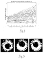
- Figure 3 shows the images recorded using a pulsed laser stripe placed at the original burner outlet during aerodynamic tests, after injecting a tracer only in the air flow produced by the diagonal swirler. There is clearly a central swirling core that continuously changes in position, rotating around the burner axis.
- thermoacoustic instability there is a strong conviction that one of the causes of thermoacoustic instability in combustion chambers is the separation of coherent and large-scale, swirling structures associated with the turbulence of the main flow. These structures are capable of disrupting the flame and thus contribute to the generation of noise in the combustion process.
- the "PVC” phenomenon is consequently an important element involved in the phenomenon of pressure fluctuation in the SW V94.3A2 burner.
- the similitude of the velocity field - or kinematic similitude - stems from the assumption of a non-viscous fluid, suitably scaling down the volumetric flow rate in the tests.
- the limits of the air flow rate that the aerodynamic test bench at the Applicant's laboratories can deliver enable tests to be conducted with a 65% kinematic similitude with the working conditions of the burner in a machine.
- the graph in figure 4 clearly shows that the velocity fluctuations measured in the prototype configuration, i.e. using the burner fitted with the discharge throat according to the invention, are considerably lower than those measured with the original burner, highlighting a greater stability of the field of motion at the burner outlet. Full-scale combustion tests confirmed the greater stability of the prototype burner.
- Figure 5 shows the comparison between the pressure fluctuation spectra measured at rated load using a 6% P/T ratio between the original burner and the burner adapted according to the invention: there is evidence of the suppression of the greatest pressure peaks typical of unstable combustion that occur with the original configuration.
- the burner according to the invention consequently assures a greater flame stability than the original burner over the entire working range, thus keeping combustion noise at a low level.
- the modification to the original burner according to the invention also enables higher specific powers to be achieved in stable operating conditions, thus extending the operating range of the gas turbine machine.
- the burner according to the invention keeps the production of the various pollutant chemical species at the same levels as the original burner.
Landscapes
- Engineering & Computer Science (AREA)
- Chemical & Material Sciences (AREA)
- Combustion & Propulsion (AREA)
- Mechanical Engineering (AREA)
- General Engineering & Computer Science (AREA)
Priority Applications (1)
| Application Number | Priority Date | Filing Date | Title |
|---|---|---|---|
| EP05425639A EP1764553A1 (fr) | 2005-09-14 | 2005-09-14 | Brûleur à prémélange à stabilité élevée pour turbine a gaz |
Applications Claiming Priority (1)
| Application Number | Priority Date | Filing Date | Title |
|---|---|---|---|
| EP05425639A EP1764553A1 (fr) | 2005-09-14 | 2005-09-14 | Brûleur à prémélange à stabilité élevée pour turbine a gaz |
Publications (1)
| Publication Number | Publication Date |
|---|---|
| EP1764553A1 true EP1764553A1 (fr) | 2007-03-21 |
Family
ID=35601784
Family Applications (1)
| Application Number | Title | Priority Date | Filing Date |
|---|---|---|---|
| EP05425639A Withdrawn EP1764553A1 (fr) | 2005-09-14 | 2005-09-14 | Brûleur à prémélange à stabilité élevée pour turbine a gaz |
Country Status (1)
| Country | Link |
|---|---|
| EP (1) | EP1764553A1 (fr) |
Cited By (4)
| Publication number | Priority date | Publication date | Assignee | Title |
|---|---|---|---|---|
| ITMI20111943A1 (it) * | 2011-10-26 | 2013-04-27 | Ansaldo Energia Spa | Metodo per modificare un gruppo bruciatore di una turbina a gas |
| RU2485398C1 (ru) * | 2011-10-20 | 2013-06-20 | Общество с ограниченной ответственностью "Энерго Эстейт" | Устройство для сжигания топлива и способ сжигания топлива |
| CN106969379A (zh) * | 2015-09-23 | 2017-07-21 | 通用电气公司 | 预混燃料喷嘴组件筒 |
| CN107763666A (zh) * | 2017-11-07 | 2018-03-06 | 中国科学院工程热物理研究所 | 一种燃烧室头部油气掺混器及具有该结构的发动机 |
Citations (6)
| Publication number | Priority date | Publication date | Assignee | Title |
|---|---|---|---|---|
| DE4109304A1 (de) * | 1991-03-21 | 1992-09-24 | Siemens Ag | Verfahren zur verringerung der stickoxid-emission eines brenners bei heizoelbetrieb und gasbetrieb |
| WO1999004196A1 (fr) * | 1997-07-17 | 1999-01-28 | Siemens Aktiengesellschaft | Agencement de bruleurs pour une installation de chauffe, notamment une chambre de combustion de turbine a gaz |
| WO1999006767A1 (fr) * | 1997-07-31 | 1999-02-11 | Siemens Aktiengesellschaft | Brûleur |
| DE19757617A1 (de) * | 1997-12-23 | 1999-03-25 | Siemens Ag | Verbrennungssystem sowie Brenner eines Verbrennungssystems |
| WO2000012939A1 (fr) * | 1998-08-31 | 2000-03-09 | Siemens Aktiengesellschaft | Ensemble bruleur |
| WO2000012933A1 (fr) * | 1998-08-26 | 2000-03-09 | Siemens Aktiengesellschaft | Bruleur hybride et procede permettant de le faire fonctionner |
-
2005
- 2005-09-14 EP EP05425639A patent/EP1764553A1/fr not_active Withdrawn
Patent Citations (6)
| Publication number | Priority date | Publication date | Assignee | Title |
|---|---|---|---|---|
| DE4109304A1 (de) * | 1991-03-21 | 1992-09-24 | Siemens Ag | Verfahren zur verringerung der stickoxid-emission eines brenners bei heizoelbetrieb und gasbetrieb |
| WO1999004196A1 (fr) * | 1997-07-17 | 1999-01-28 | Siemens Aktiengesellschaft | Agencement de bruleurs pour une installation de chauffe, notamment une chambre de combustion de turbine a gaz |
| WO1999006767A1 (fr) * | 1997-07-31 | 1999-02-11 | Siemens Aktiengesellschaft | Brûleur |
| DE19757617A1 (de) * | 1997-12-23 | 1999-03-25 | Siemens Ag | Verbrennungssystem sowie Brenner eines Verbrennungssystems |
| WO2000012933A1 (fr) * | 1998-08-26 | 2000-03-09 | Siemens Aktiengesellschaft | Bruleur hybride et procede permettant de le faire fonctionner |
| WO2000012939A1 (fr) * | 1998-08-31 | 2000-03-09 | Siemens Aktiengesellschaft | Ensemble bruleur |
Cited By (7)
| Publication number | Priority date | Publication date | Assignee | Title |
|---|---|---|---|---|
| RU2485398C1 (ru) * | 2011-10-20 | 2013-06-20 | Общество с ограниченной ответственностью "Энерго Эстейт" | Устройство для сжигания топлива и способ сжигания топлива |
| ITMI20111943A1 (it) * | 2011-10-26 | 2013-04-27 | Ansaldo Energia Spa | Metodo per modificare un gruppo bruciatore di una turbina a gas |
| WO2013061303A1 (fr) * | 2011-10-26 | 2013-05-02 | Ansaldo Energia S.P.A. | Procédé de modification d'ensemble brûleur de turbine à gaz |
| CN106969379A (zh) * | 2015-09-23 | 2017-07-21 | 通用电气公司 | 预混燃料喷嘴组件筒 |
| CN106969379B (zh) * | 2015-09-23 | 2021-08-10 | 通用电气公司 | 预混燃料喷嘴组件筒 |
| CN107763666A (zh) * | 2017-11-07 | 2018-03-06 | 中国科学院工程热物理研究所 | 一种燃烧室头部油气掺混器及具有该结构的发动机 |
| CN107763666B (zh) * | 2017-11-07 | 2023-08-04 | 中国科学院工程热物理研究所 | 一种燃烧室头部油气掺混器及具有该结构的发动机 |
Similar Documents
| Publication | Publication Date | Title |
|---|---|---|
| US11519334B2 (en) | Torch igniter for a combustor | |
| US7966801B2 (en) | Apparatus and method for gas turbine active combustion control system | |
| EP2559946B1 (fr) | Système et procédé de réduction des dynamiques de combustion dans une chambre de combustion | |
| JP2010223577A (ja) | スワーラ、少なくとも1つのスワーラを備えたバーナにおける逆火の防止方法およびバーナ | |
| JP2010223577A6 (ja) | スワーラ、少なくとも1つのスワーラを備えたバーナにおける逆火の防止方法およびバーナ | |
| JP2011017334A (ja) | タービン燃焼器燃料ノズル内の保炎及び逆火のアクティブ制御 | |
| JP5820574B2 (ja) | ガスタービンの燃焼ダイナミクスを制御するシステム及び方法 | |
| EP2613086A2 (fr) | Prémélangeur air-carburant pour chambre à combustion de turbine à gaz avec appareil de tourbillonnement variable | |
| JP2010223577A5 (fr) | ||
| US20220026068A1 (en) | Fuel nozzle for gas turbine engine combustor | |
| US7051530B2 (en) | Burner apparatus for burning fuel and air | |
| US5758587A (en) | Process and device for suppression of flame and pressure pulsations in a furnace | |
| JP2008292138A (ja) | 燃焼装置及びバーナの燃焼方法 | |
| US6978619B2 (en) | Premixed burner with profiled air mass stream, gas turbine and process for burning fuel in air | |
| JP2019536976A (ja) | 燃料/空気の混合が改良されたスワーラ、燃焼器アセンブリおよびガスタービン | |
| EP2511607A2 (fr) | Buse de chambre de combustion et procédé pour fournir du carburant à une chambre de combustion | |
| EP1764553A1 (fr) | Brûleur à prémélange à stabilité élevée pour turbine a gaz | |
| US11592182B1 (en) | Swirler ferrule plate having pressure drop purge passages | |
| Paschereit et al. | The effectiveness of passive combustion control methods | |
| Koomen et al. | High Pressure Testing With Optical Diagnostics of a Hydrogen Retrofit Solution to Eliminate Carbon Emissions | |
| EP2284441A2 (fr) | Brûleur de turbine à gaz | |
| US20200018232A1 (en) | Independently controlled three stage water injection in a diffusion burner | |
| Tong et al. | An experimental study of effects of confinement ratio on swirl stabilized flame macrostructures | |
| CN114659105B (zh) | 一种直棒式预混燃烧器及低氮燃烧方法 | |
| Paschereit et al. | Enhanced stability and reduced emissions in an elliptic swirl-stabilized burner |
Legal Events
| Date | Code | Title | Description |
|---|---|---|---|
| PUAI | Public reference made under article 153(3) epc to a published international application that has entered the european phase |
Free format text: ORIGINAL CODE: 0009012 |
|
| AK | Designated contracting states |
Kind code of ref document: A1 Designated state(s): AT BE BG CH CY CZ DE DK EE ES FI FR GB GR HU IE IS IT LI LT LU LV MC NL PL PT RO SE SI SK TR |
|
| AX | Request for extension of the european patent |
Extension state: AL BA HR MK YU |
|
| AKX | Designation fees paid | ||
| REG | Reference to a national code |
Ref country code: DE Ref legal event code: 8566 |
|
| STAA | Information on the status of an ep patent application or granted ep patent |
Free format text: STATUS: THE APPLICATION IS DEEMED TO BE WITHDRAWN |
|
| 18D | Application deemed to be withdrawn |
Effective date: 20070922 |