EP1764291A2 - Automotive vehicle framing system - Google Patents
Automotive vehicle framing system Download PDFInfo
- Publication number
- EP1764291A2 EP1764291A2 EP06019683A EP06019683A EP1764291A2 EP 1764291 A2 EP1764291 A2 EP 1764291A2 EP 06019683 A EP06019683 A EP 06019683A EP 06019683 A EP06019683 A EP 06019683A EP 1764291 A2 EP1764291 A2 EP 1764291A2
- Authority
- EP
- European Patent Office
- Prior art keywords
- plate
- coupler
- docking
- tool arm
- locator
- Prior art date
- Legal status (The legal status is an assumption and is not a legal conclusion. Google has not performed a legal analysis and makes no representation as to the accuracy of the status listed.)
- Granted
Links
Images


Classifications
-
- B—PERFORMING OPERATIONS; TRANSPORTING
- B62—LAND VEHICLES FOR TRAVELLING OTHERWISE THAN ON RAILS
- B62D—MOTOR VEHICLES; TRAILERS
- B62D65/00—Designing, manufacturing, e.g. assembling, facilitating disassembly, or structurally modifying motor vehicles or trailers, not otherwise provided for
- B62D65/02—Joining sub-units or components to, or positioning sub-units or components with respect to, body shell or other sub-units or components
-
- B—PERFORMING OPERATIONS; TRANSPORTING
- B23—MACHINE TOOLS; METAL-WORKING NOT OTHERWISE PROVIDED FOR
- B23K—SOLDERING OR UNSOLDERING; WELDING; CLADDING OR PLATING BY SOLDERING OR WELDING; CUTTING BY APPLYING HEAT LOCALLY, e.g. FLAME CUTTING; WORKING BY LASER BEAM
- B23K37/00—Auxiliary devices or processes, not specially adapted to a procedure covered by only one of the preceding main groups
- B23K37/04—Auxiliary devices or processes, not specially adapted to a procedure covered by only one of the preceding main groups for holding or positioning work
- B23K37/0426—Fixtures for other work
- B23K37/0452—Orientable fixtures
-
- B—PERFORMING OPERATIONS; TRANSPORTING
- B23—MACHINE TOOLS; METAL-WORKING NOT OTHERWISE PROVIDED FOR
- B23K—SOLDERING OR UNSOLDERING; WELDING; CLADDING OR PLATING BY SOLDERING OR WELDING; CUTTING BY APPLYING HEAT LOCALLY, e.g. FLAME CUTTING; WORKING BY LASER BEAM
- B23K37/00—Auxiliary devices or processes, not specially adapted to a procedure covered by only one of the preceding main groups
- B23K37/04—Auxiliary devices or processes, not specially adapted to a procedure covered by only one of the preceding main groups for holding or positioning work
- B23K37/047—Auxiliary devices or processes, not specially adapted to a procedure covered by only one of the preceding main groups for holding or positioning work moving work to adjust its position between soldering, welding or cutting steps
-
- B—PERFORMING OPERATIONS; TRANSPORTING
- B23—MACHINE TOOLS; METAL-WORKING NOT OTHERWISE PROVIDED FOR
- B23K—SOLDERING OR UNSOLDERING; WELDING; CLADDING OR PLATING BY SOLDERING OR WELDING; CUTTING BY APPLYING HEAT LOCALLY, e.g. FLAME CUTTING; WORKING BY LASER BEAM
- B23K2101/00—Articles made by soldering, welding or cutting
- B23K2101/006—Vehicles
-
- Y—GENERAL TAGGING OF NEW TECHNOLOGICAL DEVELOPMENTS; GENERAL TAGGING OF CROSS-SECTIONAL TECHNOLOGIES SPANNING OVER SEVERAL SECTIONS OF THE IPC; TECHNICAL SUBJECTS COVERED BY FORMER USPC CROSS-REFERENCE ART COLLECTIONS [XRACs] AND DIGESTS
- Y10—TECHNICAL SUBJECTS COVERED BY FORMER USPC
- Y10T—TECHNICAL SUBJECTS COVERED BY FORMER US CLASSIFICATION
- Y10T29/00—Metal working
- Y10T29/49—Method of mechanical manufacture
- Y10T29/49764—Method of mechanical manufacture with testing or indicating
- Y10T29/49778—Method of mechanical manufacture with testing or indicating with aligning, guiding, or instruction
- Y10T29/4978—Assisting assembly or disassembly
-
- Y—GENERAL TAGGING OF NEW TECHNOLOGICAL DEVELOPMENTS; GENERAL TAGGING OF CROSS-SECTIONAL TECHNOLOGIES SPANNING OVER SEVERAL SECTIONS OF THE IPC; TECHNICAL SUBJECTS COVERED BY FORMER USPC CROSS-REFERENCE ART COLLECTIONS [XRACs] AND DIGESTS
- Y10—TECHNICAL SUBJECTS COVERED BY FORMER USPC
- Y10T—TECHNICAL SUBJECTS COVERED BY FORMER US CLASSIFICATION
- Y10T29/00—Metal working
- Y10T29/49—Method of mechanical manufacture
- Y10T29/49826—Assembling or joining
- Y10T29/49895—Associating parts by use of aligning means [e.g., use of a drift pin or a "fixture"]
- Y10T29/49897—Registering mating opposed tool parts [e.g., registering a punch and a cooperating die]
-
- Y—GENERAL TAGGING OF NEW TECHNOLOGICAL DEVELOPMENTS; GENERAL TAGGING OF CROSS-SECTIONAL TECHNOLOGIES SPANNING OVER SEVERAL SECTIONS OF THE IPC; TECHNICAL SUBJECTS COVERED BY FORMER USPC CROSS-REFERENCE ART COLLECTIONS [XRACs] AND DIGESTS
- Y10—TECHNICAL SUBJECTS COVERED BY FORMER USPC
- Y10T—TECHNICAL SUBJECTS COVERED BY FORMER US CLASSIFICATION
- Y10T29/00—Metal working
- Y10T29/49—Method of mechanical manufacture
- Y10T29/49826—Assembling or joining
- Y10T29/49895—Associating parts by use of aligning means [e.g., use of a drift pin or a "fixture"]
- Y10T29/49899—Associating parts by use of aligning means [e.g., use of a drift pin or a "fixture"] by multiple cooperating aligning means
-
- Y—GENERAL TAGGING OF NEW TECHNOLOGICAL DEVELOPMENTS; GENERAL TAGGING OF CROSS-SECTIONAL TECHNOLOGIES SPANNING OVER SEVERAL SECTIONS OF THE IPC; TECHNICAL SUBJECTS COVERED BY FORMER USPC CROSS-REFERENCE ART COLLECTIONS [XRACs] AND DIGESTS
- Y10—TECHNICAL SUBJECTS COVERED BY FORMER USPC
- Y10T—TECHNICAL SUBJECTS COVERED BY FORMER US CLASSIFICATION
- Y10T29/00—Metal working
- Y10T29/49—Method of mechanical manufacture
- Y10T29/49826—Assembling or joining
- Y10T29/49895—Associating parts by use of aligning means [e.g., use of a drift pin or a "fixture"]
- Y10T29/49902—Associating parts by use of aligning means [e.g., use of a drift pin or a "fixture"] by manipulating aligning means
-
- Y—GENERAL TAGGING OF NEW TECHNOLOGICAL DEVELOPMENTS; GENERAL TAGGING OF CROSS-SECTIONAL TECHNOLOGIES SPANNING OVER SEVERAL SECTIONS OF THE IPC; TECHNICAL SUBJECTS COVERED BY FORMER USPC CROSS-REFERENCE ART COLLECTIONS [XRACs] AND DIGESTS
- Y10—TECHNICAL SUBJECTS COVERED BY FORMER USPC
- Y10T—TECHNICAL SUBJECTS COVERED BY FORMER US CLASSIFICATION
- Y10T29/00—Metal working
- Y10T29/53—Means to assemble or disassemble
-
- Y—GENERAL TAGGING OF NEW TECHNOLOGICAL DEVELOPMENTS; GENERAL TAGGING OF CROSS-SECTIONAL TECHNOLOGIES SPANNING OVER SEVERAL SECTIONS OF THE IPC; TECHNICAL SUBJECTS COVERED BY FORMER USPC CROSS-REFERENCE ART COLLECTIONS [XRACs] AND DIGESTS
- Y10—TECHNICAL SUBJECTS COVERED BY FORMER USPC
- Y10T—TECHNICAL SUBJECTS COVERED BY FORMER US CLASSIFICATION
- Y10T403/00—Joints and connections
- Y10T403/60—Biased catch or latch
Definitions
- the present invention relates to an automotive framing system, or any other geometry station, for accurately positioning vehicle body components relative to each other prior to securing the vehicle body components together.
- a conveyor system In the manufacture of automotive vehicles, a conveyor system typically transports a body preassembly sequentially along a conveyor line.
- body preassemblies supported by a vehicle carrier comprise various body components, such as an underbody, front structure, body sides, headers, etc., which are loosely attached to each other in their approximate final assembly position relative to each other.
- a gantry is positioned above the assembly station at a midpoint of the conveyor line.
- the gantry includes swing arms which are movable between a raised and a lowered position. In their raised position, the swing arms are positioned away from the body preassembly which enables the next preassembly to be moved by the conveyor system into the assembly station.
- the arms Conversely, in their engaged position, the arms swing downwardly approaching "damp units" supporting reference blocks and clamps to engage predetermined reference surfaces or location points of the various vehicle body components, and clamp the body components together at a predetermined position relative to each other.
- robotic welders or the like extend through openings in the reference frame and are used to fixedly secure the body components together by "tack welds".
- a reference frame is positioned around the body preassembly when the preassembly is positioned at the assembly station.
- pivoting or sliding units connected to the reference frame and supporting reference blocks and clamps extend into the interior of the automotive vehicle body components to engage the reference surfaces of the body components, and lock the body components together at a predetermined position relative to each other prior to welding.
- a side gate is positioned along each side of the assembly station. These side gates are movable between a retracted position, in which the gates are positioned laterally outside the assembly station to permit the body preassembly to be moved into the assembly station, and an assembly position in which the gates are positioned along each outer side of the body preassembly. Pivoting or siding units mounted onto the gates and supporting clamping assemblies then extend into the vehicle body components to secure the body components in the desired predetermined position relative to each other. Thereafter, robotic welders extend through openings in the gate, into the vehicle and "tack weld" the vehicle body components together.
- a still further disadvantage of these previously known framing systems is that, after the body preassembly has been moved into the assembly station and clamped at the desired position relative to each other, it is necessary for robotic welders to then extend through openings in either the gate or the reference frame in order to weld the body components together. Due to interference between the robotic welders and either the gate or reference frame, the use of complex and time-consuming robot trajectories, and thus expensive robotic engineering study, has been required.
- a still further disadvantage of these previously known framing systems is that it is necessary to use a different reference frame or a different gate even for slightly different vehicle body styles. Since multiple body styles are oftentimes assembled together at a single assembly station, it has been previously necessary to move either different reference frames or different gates to the assembly station in order to accommodate the different vehicle body styles. Since these previously known reference frames and gates are massive in construction and require a long design and fabrication time, they are expensive and may delay the time to put a new vehicle on the market. Furthermore, these systems require a large footprint on the shop floor to store the unused set of tools.
- the present invention provides an automotive framing system for a vehicle body which overcomes all of the above-mentioned disadvantages of the previously known devices by splitting the traditional large tool frame in a set of elementary tool arms with which the robot can develop its full agility to set in position.
- the vehicle framing system of the present invention comprises an assembly station having spaced-apart frame members.
- a vehicle carrier which supports the vehicle body components in a preassembled condition is then moved into the assembly station by a conventional conveyor.
- these spaced-apart frame members can be vertically movable but preferably stationary.
- At least two docking stations are secured to each frame member at predetermined positions along the frame member.
- One or more tool arm is associated with each docking station and each tool arm includes at least one set of reference blocks or locating pins and its clamp designed to engage a reference surface on one of the vehicle body components to secure the vehicle body components at predetermined positions relative to each other.
- a robot is associated with each tool arm and will preferably carry both its welding gun and its associated tool arm to avoid lost time in switching one for the other.
- the robot moves each tool arm between an assembly position and a vehicle loading position where other tool arms dedicated to other vehicle types are stored.
- each robot manipulates its tool arm into the body frame thus bringing the stationary reference block into contact with the corresponding location surface.
- each tool arm abuts against its associated docking station so that each tool arm is positioned at the assembly station at a predetermined position relative to the frame members at the assembly station.
- a tool arm clamp mounted on each docking station clamps the tool arm to its associated docking position at a predetermined position and a media quick coupling provides pressurized air and electric connections to energize the clamps or any other air cylinder or proximity switches.
- each robot disengages from its associated tool arm, while at the same time all the clamping sequence is achieved. Thereafter, a welder carried by at least one of the robots extends into the body vehicle preassembly in order to fixedly secure the body components together at their predetermined position relative to each other thus completing the body assembly.
- the clamps are released and each robot reengages with its associated tool arm. Thereafter, the tool arm clamps disengage thus releasing the tool arms from their associated docking stations. The robots then move the tool arms laterally outwardly to their vehicle loading position, and depending on the next vehicle to frame or a specific process, it may either keep the same tool arm or drop it to "respot" the current vehicle, or take a new tool arm matching the new vehicle type. Thereafter, the now assembled vehicle body assembly is moved by the conveyor out of the assembly station while a new vehicle carrier supporting a new body preassembly is moved into the assembly station and the above process is repeated.
- a primary advantage of the framing system of the present invention is that the robots are able to manipulate the tool arms so that a portion of one or more of the tool arms extend into the body preassembly and closely adjacent the body component reference surfaces.
- relatively inexpensive clamping assemblies carried by each tool arm are employed to not only rapidly, but also accurately, position the vehicle body components together in preparation for final assembly. Since relatively simple clamping assemblies are used to position the vehicle body components, inaccuracies caused by wear and/or design of the previously known articulated clamps are avoided and welding robot accessibility is maximized.
- a still further advantage of the automotive framing system of the present invention is that different tool arms may be easily engaged and manipulated by the robots in order to accommodate different body styles. Furthermore, in case of robot interference or crash or other tool arm malfunction, only a simple fraction of the tooling will need to be fixed and geometrically recalibrated.
- the present invention allows up to four or five medium capacity welding robots per side for a pure floor-mounted configuration and, if necessary, four to six additional robots mounted on a balcony, reducing the overall cycle time for a given number of tack-welds to be performed.
- FIG. 1 a preferred embodiment of the automotive framing system 10 of the present invention is shown for use with a manufacturing line for automotive vehicles.
- the term "framing system” encompasses not only the vehicle frame of an automotive vehicle, but also any application where accurate positioning of two or more body components is desired.
- a framing system would also include fender setting, roof setting, door setting, as well as other vehicle body components than the vehicle frame.
- each vehicle body carrier 14 supports a body preassembly 18 comprising a plurality of body vehicle components 20.
- the body vehicle components 20 are only loosely fastened together in their approximate final assembly position by restraining tags, also known as toy tabs, or other conventional means (not shown).
- the vehicle body carrier 14 is conventionally known as a skid or a geometry pallet in the automotive industry.
- the assembly station 16 is shown in greater detail and comprises a pair of spaced-apart frame members 22 which extend along opposite sides of the vehicle body carrier 14 and thus along opposite sides of the body preassembly 18.
- crossbeams 24 extend laterally between the frame members 22 to lock the frame members 22 together in a predetermined fixed position.
- At least two and preferably three or four docking stations 26 are provided along each side of the assembly station 16.
- Each docking station 26 is fixedly secured to the frame members 22 so that the position of each docking station 26 is fixed relative to the frame member 22 and thus relative to the assembly station 16.
- each docking station 26 includes at least one and preferably three locator pins 28 so that each locator pin 28 is positioned at an apex of a triangular surface 30, preferably oriented at 45 degrees from the horizontal on the docking station 26.
- each locator pin 28 is preferably frusto-conical in shape with a preferred conicity angle of 90 degrees, and the pins 28 are fixedly secured to their associated docking stations 26.
- Each docking station 26 also includes a media quick coupling 58 (FIGS. 3 and 5) which provides pressurized air and electric signals to the associated clamp arm in order to energize the framing clamps 64 as well as other air cylinder or proximity switches.
- media quick coupling 58 FIGS. 3 and 5
- the framing system further includes a plurality of tool arms 40 which, as will be shortly described, selectively clamp the vehicle body components 20 together at a predetermined position relative to each other prior to final assembly. It will be understood, of course, that the precise configuration of each tool arm 40 will vary depending upon the type of vehicle assembled at the assembly station 16. Consequently, the tool arms 40 illustrated in the drawing are for illustration purposes only.
- the tool arm 40 includes a main body 42 which is constructed of any rigid but light material, such as ribbed thin-walled steel, aluminum or magnesium alloy.
- a locating surface 44 (FIG. 3) at one end of the tool arm body 42 includes at least one and preferably three locating sockets 46.
- the locating sockets 46 are complementary in shape and number to the locating pins 28.
- the locating sockets 46 are positioned on the surface 44 of the tool arm 40 such that one socket 46 corresponds to and is aligned with one locating pin 28 on the docking station 26.
- the shape of the tool arm main body 42 will have a tetrahedral profile, with a triangular basis matching the locating socket outer pattern.
- a robotic arm 50 (FIG. 4) of a robot 52 (FIG. 1) is associated with each tool arm 40. Furthermore, the robotic arm 50 is selectively secured to its associated tool arm 40 by a conventional robotic coupling 51 so that the robotic arm 50 moves its associated tool arm 40 between retracted a vehicle loading position and an assembly position. In the vehicle loading position, the robotic arm 50 moves its associated tool arm 40 laterally outwardly from the assembly station 16 to enable a new body preassembly to be moved into the assembly station. Conversely, in its assembly position, the robotic arm 50 selectively moves its associated tool arm 40 so that the reference blocks 60, e.g.
- At least one, and more typically two or more, framing clamps 64 are secured to each tool arm 40.
- These framing clamps 64 once the robotic arm 50 has positioned the reference blocks 60 of its associated tool arm 40 onto the body shell, and its associated tool arm 40 on the docking station 26, engage across clamping surfaces 62 on the body components 20.
- the framing clamps 64 Upon activation of the framing clamps 64, the framing clamps 64 secure the body components 18 against the reference block 60 at a predetermined position relative to the assembly station frame member 22 and thus relative to each other.
- the body preassembly 18 is ready to be secured or welded together.
- the robotic arm 50 disengages from its associated tool arm body 42 by unlocking the robotic coupling 52.
- a welding gun 70 attached to the robotic arm 50 is then manipulated by the robotic arm 50 into the body preassembly 18. Upon activation of the welding gun 70, the welding gun 70 secures the body components 20 together thus completing the automotive body assembly.
- each robotic arm 50 then reengages with its associated tool arm 40 by locking the tool arm 40 to the robotic arm 50 by the coupling 51 as shown in FIG. 4.
- all the framing clamps 64 are released.
- the tool arm clamp assembly 54 (FIG. 5) is actuated to its unlocked position thus enabling the tool arm 40 to disengage from its associated docking station 26.
- the framing clamps 64 are also opened, so that each robotic arm 50 is then able to move its associated tool arm 40 from the assembly position to a vehicle loading position at a position spaced laterally outwardly from the framing station 16.
- the robot will drop the previous tool arm 40 in its tool arm storage 27 (FIG. 1) and pick a new one suitable for the new model.
- the now assembled automotive body is moved by the conveyor 12 out of the assembly station 16, a new vehicle carrier 14 with its body preassembly 18 is moved into the assembly station 16 and the above process is repeated.
- each robotic arm 50 is able to manipulate portions of its associated tool arm 40 into the interior of the body preassembly 18 so that stationary reference blocks 60 are positioned closely adjacent the reference surfaces on the body components 20.
- the robotic arm 50 may be used to manipulate its associated tool arm 40 to move sections of the tool arm 40 through relatively small openings 68 of the body preassembly 18 prior to attaching the tool arm 40 to its docking station 26 as shown in solid line.
- This permits inexpensive and accurate stationary reference block 60 and rapid acting clamps 64 to be used to secure the body components 20 together at their desired position prior to assembly.
- a still further advantage of the present invention is that different vehicle body styles may be assembled at the same assembly station 16 and using the same robots 52. More specifically, since the robotic arms 50 of the robots 52 selectively engage and disengage from their associated tool arms 40, the robotic arms 50 may also selectively engage different tool arms 40 in order to accommodate different automotive body styles. As such, by merely selectively engaging and disengaging with different tool arms 40, different body styles may be easily accommodated and assembled at the same assembly station 16. Because of the modularity of the tool set used, if the design of two different bodies presents some commonality, such as a front block, only a fraction of the tool set can be changed to frame this different body.
- the robotic coupling 151 includes a plate 152 having two ends 154 and 156 and two spaced-apart sides 158 and 160.
- the plate 152 is secured to the tool arm 40 in any conventional fashion, such as by bolts or other threaded fasteners.
- the sides 158 and 160 of the plate 152 taper away from each other from the bottom end 156 and to the top end 154 of the plate 152. Furthermore, as best shown in FIG. 11, an upper surface 159 and 161 of the sides 158 and 160, respectively, taper toward each other.
- the robotic coupling 51 further includes a coupler 162 which is secured to the robotic arm 50, either directly or through a tool attached to this robotic arm, in any conventional fashion, such as by bolts.
- the coupler 162 includes a top 164, bottom 168 and sides 170 and 172 which, together, define a cavity 174 which is complementary in shape to the plate 154. Consequently, the sides 170 and 172 of the coupler 162 taper outwardly from the bottom 168 and to its top 164. Additionally, the upper surfaces of the sides 170 and 172 are tapered inwardly as shown at 174 and 176, respectively, as best shown in FIG. 11.
- the top 164 of the coupler 162 is open so that the plate 152 may be flatly positioned against a bottom 178 of the coupler 162 with the ends 168 and 156 of the coupler 162 and plate 152 spaced apart from each other. In this position, the plate 152 and coupler 162 are in a disengaged position in which the coupler 162 with its attached robotic arm 50 may be moved independently of the plate 152 with its attached tool arm 140.
- the plate 152 nests within the cavity 174.
- the sides 158 and 160 of the plate 152 dovetail with the sides 170 and 172 of the coupler 162 to lock the plate 152 and coupler 162 together against relative movement.
- the robotic arm 50 may be used to manipulate the tool arm 40 in the desired fashion.
- a latch assembly 190 is contained within the coupler 162 for selectively locking the coupler 162 and plate 152 together when the plate 152 and coupler 162 are in their engaged position (FIG. 9).
- This latch assembly 190 includes a latch bar 192 which is pivotally mounted by a pin 200 to the coupler 162.
- An actuator plate 194 is mounted to the coupler 162 and has an end 216 pivotally connected to the latch bar 192 so that the latch bar 192 pivots about the pin 200 in unison with movement of the actuator plate 194.
- the actuator plate 194 is movable between an extended position, illustrated in FIG. 17, and a retracted position illustrated in FIG. 16. In its extended position, the latch bar 192 protrudes outwardly from the bottom 178 of the coupler 162 and conversely, in its retracted position (FIG. 14), the latch bar 192 is generally flush with the bottom 190 of the coupler 162.
- a pair of compression springs 202 are entrapped in a state of compression between the coupler 162 and the latch bar 192.
- the springs 202 urge the latch bar 192 towards its extended position illustrated in FIG. 12.
- a resilient diaphragm 204 is attached to the coupler 162 by an annular seal ring 206 thus forming a fluid chamber 208 between the diaphragm 204 and the coupler 162.
- This fluid chamber 208 is fluidly accessible through a fluid port 210 (FIG. 11).
- the diaphragm 204 together with its seal ring 206, preferably includes substantially diametrically opposed, upwardly extending wings 212. These wings facilitate access to the chamber 208 by the fluid port 210 while still retaining a very thin profile for the coupler 162.
- the robotic arm 50 moves the coupler 162 in the direction of arrow 220 toward the plate 152.
- the end 156 of the plate 152 is spaced upwardly from the end 168 of the coupler 162 so that the plate 152 may be flatly positioned against the bottom 174 of the coupler 162 as shown in FIG. 13.
- the plate 152 engages the outwardly protruding latch bar 192 and pivots the latch bar 192 from its extended position shown in FIG. 12 and to its retracted position shown in FIG. 13.
- the robotic arm 50 moves the coupler 162 in the direction of arrow 222, i.e. in an end-to-end direction relative to both the coupler 162 and plate 152, to the engaged position illustrated in FIG. 14.
- the sides of the coupler 162 and plate 152 abut, or nearly abut, together thus locking the plate 152 and coupler 162 together.
- the latch bar 192 registers with an opening 224 in the plate 152 and the force of the springs 202 return the latch bar 192 to its extended position (FIG. 14).
- the latch bar 192 is positioned within the opening 224 thus locking the plate 152 and coupler 162 together against end-to-end movement while the dovetail nesting of the sides of the coupler 162 and plate 152 locks the coupler 162 and plate 152 together against movement in the other axis.
- the robot 50 may then be used to manipulate the tool arm 40 to the position desired.
- the chamber 208 is pressurized thus moving the actuator plate 194 to an extended position and pivoting the latch bar 192 to its retracted position as shown in FIG. 15.
- the robotic arm 50 With the latch bar 192 in its retracted position, the robotic arm 50 then moves the coupler 162 in a downwardly end-to-end movement in the direction indicated by arrow 230 thus disengaging the plate 152 from the coupler 162.
- the robotic arm 50 then moves the coupler 162 to a completely disengaged position from the plate 152 as shown in FIG. 17.
- the chamber 208 is depressurized in FIG. 17 thus returning the latch bar 192 to its extended position under the force of the springs 202.
- an opening 232 is provided through the coupler 162. This opening is aligned with an area below the actuator plate 194 adjacent the latch bar 192. Consequently, insertion of a tool, such as a screwdriver, enables the latch bar 192 to be mechanically pivoted by the tool to its retracted position thus releasing the plate 152 from the coupler 162.
- the robotic coupling illustrated in FIGS. 8-17 enjoys many advantages over the previously known robotic couplings. Perhaps most importantly, the robotic coupling 151 is not only lightweight, but also enjoys a very thin profile since both the coupler 162 as well as the plate 152 may be thin in thickness, e.g. approximately one inch. Furthermore, the present invention provides a secure attachment between the plate 152 and the coupler 162 due to the dovetail connection between the plate 152 and coupler 162. In addition, only limited movement of the robotic arm 50 is required in order to move the plate 152 and coupler 162 between their engaged and disengaged positions.
- FIGS. 18 and 32 a still further preferred embodiment of a docking station 26' in which, as before, the docking station 26' includes a housing 299 having docking surface 300 having three frusto-conical locator pins 302 positioned on the surface 30 in a triangular pattern.
- a T-shaped brace 304 is contained within the docking station 26' so that each end of the T-shaped brace 304 is aligned with a center of one of the locator pins 302. As such, all compressive force exerted against the locator pins 302 is transmitted solely to the T-shaped brace 304 rather than the housing for the docking station 26'.
- the tool arm 40 includes three locator sockets 306 mounted on a docking surface 308. These locator sockets 306 are complementary in shape to the locator pins 302 on the docking station 26' (FIG. 18). Additionally, the sockets 306 are mounted on the docking surface 308 such that one locator socket 306 s aligned with one locator pin 302 when the tool arm 40 is docked on the docking station 26'.
- a T-shaped brace 314 is contained within the tool arm 40 so that each end 316 (FIG. 23) is aligned with and connected to a center of each locator socket 306.
- a Belleville washer 318 is disposed between at least one end 316 of the T-shaped brace 304 and its associated locator pin 302.
- a retainer 320 having a retainer opening 322 is secured to the T-shaped brace 314. Consequently, all axial forces exerted on the retainer 320 are transmitted directly through the locator sockets 306 and locator pins 302 and their associated T-shaped braces 314 and 304, respectively.
- an actuator assembly 330 is contained within the docking station 299 for selectively locking the tool holder 40 and docking station 26' together.
- the actuator assembly includes a hook 332 which is pivotally mounted to an eccentric shaft 334 which in turn is pivotally mounted to the T-shaped brace 304.
- a pair of cam plates 336 are positioned along opposite sides of the hook 332.
- the cam plates 336 are secured to the shaft 334 by a key 337 so that the cam plates 336 pivot in unison with the eccentric shaft 334.
- a linear actuator 340 pivots both the cam plates 336 and hook 332 between an unlocked position, illustrated in FIG. 19, and the locked position, illustrated in FIG. 22 in a fashion to be shortly described.
- the linear actuator 340 In its unlocked position (FIG. 19), the linear actuator 340 is in its extended position.
- a dowel 342 extending between the cam plates 336 engages a stop 344 on the hook 332.
- the dowel pin 342 maintains the hook 332 in its unlocked position against the force of one or more tension springs 348.
- the robot is used to manipulate and position the tool arm 40 on top of the docking station 26' such that the three locator sockets 306 on the tool arm 40 engage with the three locator pins 302 on the docking station 26'.
- the location of the locator sockets and locator pins may be reversed, i.e. the locator sockets are positioned on the docking station 26' while the locator pins are positioned on the tool arm 40.
- a mixture of locator sockets and locator pins to be provided on both the docking station 26' and tool arm 40 as long as one locator socket engages each of the locator pins.
- the actuator 340 is partially retracted to the position shown in FIG. 21.
- the tension springs 348 pivot the hook 332 to the position shown in FIG. 21 in which the hook extends through the opening 322 in the retainer 320 thus locking the tool arm 40 to the docking station 26'.
- the linear actuator 340 is further retracted to the final position illustrated in FIG. 22 and, in doing so, moves the hook 332 in a direction normal to the tool arm 40 as indicated by arrow 350 due to the eccentricity of the shaft 334. This normal movement of the hook 332 thus compresses the tool arm 40 and docking station 26' together through the locator pins 302 and sockets 306.
- the retainer 320 is mounted directly to the T-shaped brace 314 while, similarly, the eccentric shaft 334 is rotatably mounted to the T-shaped brace 304 contained within the docking station 26'. Consequently, the entire tensile force exerted between the hook 332 and the retainer 320 when the actuator 340 is moved to its final retracted position shown in FIG. 22 is transmitted solely through the T-shaped members 314 and 304.
- both the docking station 26' as well as the tool holder 40 are isolated from any deflection or distortion caused by the tensile force between the hook 332 and retainer 320 and the corresponding offsetting compressive force between the locator pins and sockets. Instead, any deflection or distortion caused by the compressive force between the hook 332 and retainer 320 is borne entirely by the T-shaped braces 314 and 304.
- the cam plate 336 engages a cam follower 337 on an electrical connection box 352 and pivots the box 352 from a retracted position, illustrated in FIG. 21, to an extended position, illustrated in FIG. 25 about a pivot axis 354.
- the electrical box 352 contains one or more spring loaded electrical contacts and is conventional in construction.
- the box 336 when in its extended position (FIG. 22), provides one or more electrical connections between the docking stations 26' and the tool holder 40.
- the attachment between the docking station 26' and the tool support 40 not only eliminates distortion of both the tool support 40 and docking station 26' by transferring any such distortion to the T-shaped braces 314 and 304, but is also simple and fail proof in construction.
- a fluid port plate 360 is mounted on the docking surface 300 of the docking station 26'. This port plate 360 includes one or more fluid ports 362.
- the fluid coupling assembly 364 is also connected to the tool holder 40.
- the fluid coupling assembly 364 includes a housing 366 having one or more fluid lines 368 extending outwardly from the housing.
- one fluid line 368 is there shown in greater detail and includes a bore 370 formed through the housing 366 and threaded at its upper end 372.
- a pair of aligned bushings 374 and 375 are disposed within the bore 370 and an O-ring 376 is positioned between the bushings 374 and 375.
- One bushing 375 preferably the inner one submitted to air chamber pressure, also includes a notch 378 to facilitate removal and replacement of the O-ring 376 when required.
- a tubular piston 380 is axially slidably mounted within the bushings 374 and 375 and includes an outwardly extending lip 382 at its upper end. This lip 382 abuts against the top of the bushing 374 and retains the piston 380 within the bushings 374 and 375 while the O-ring 376 fluidly seals the piston 380 to the bushings 374 and 375 and housing 366.
- a tubular plug 384 threadably engages the threaded end 372 of the housing bore 370 and, in turn, includes an internally threaded bore 386 aligned with the piston 380.
- a conventional fluid coupling 388 is then threadably connected to the threaded plug bore 384.
- a lightweight compression spring 390 is compressed between the plug 384 and an annular abutment surface 392 on the piston 380. Additionally, an O-ring 396 is attached to and protrudes outwardly from the free end of the piston 380.
- the fluid pressure causes the piston 380 to shift axially in the direction of arrow 398 toward the port plate 360.
- the amount of axial displacement of the piston 380 from the position shown in FIG. 28 prior to pressurization and to the position shown in FIG. 29 after pressurization is exaggerated in the drawing for added clarity.
- the axial displacement of the piston 380 in the direction of arrow 398 compresses the O-ring 396 thus establishing the fluid seal between the piston 380 and the fluid port 362.
- a primary advantage of the fluid coupling illustrated in FIGS. 26-29 is that the direction of approach between the tool support 40 and docking station 26 may be at an angle of up to 90 degrees off center and requires only minimal axial displacement between the tool arm and the docking station 26' once the pistons 380 and fluid port 362 are aligned. This, in turn, allows greater flexibility in the design of the tooling attached to the tool arm that is required for the previously known fluid couplings which require extended axial movement between the tool arm and the docking station in order to achieve the necessary fluid connection.
Landscapes
- Engineering & Computer Science (AREA)
- Mechanical Engineering (AREA)
- Physics & Mathematics (AREA)
- Optics & Photonics (AREA)
- Manufacturing & Machinery (AREA)
- Chemical & Material Sciences (AREA)
- Combustion & Propulsion (AREA)
- Transportation (AREA)
- Automatic Assembly (AREA)
- Manipulator (AREA)
- Automobile Manufacture Line, Endless Track Vehicle, Trailer (AREA)
Abstract
Description
- This application claim the benefit of
U.S. Patent Application Serial No. 11/230,715 filed September 20, 2005 - The present invention relates to an automotive framing system, or any other geometry station, for accurately positioning vehicle body components relative to each other prior to securing the vehicle body components together.
- In the manufacture of automotive vehicles, a conveyor system typically transports a body preassembly sequentially along a conveyor line. Such body preassemblies supported by a vehicle carrier comprise various body components, such as an underbody, front structure, body sides, headers, etc., which are loosely attached to each other in their approximate final assembly position relative to each other.
- In order to fixedly secure the body components together, it is imperative that the body components be precisely positioned relative to each other to freeze their geometry by "tack welds" performed in this framing station, prior to a "respot" of the whole body in order to provide its final strength. To accomplish such precision positioning of the body components, there have been previously known automotive framing systems.
- In one prior art automotive framing system, a gantry is positioned above the assembly station at a midpoint of the conveyor line. The gantry includes swing arms which are movable between a raised and a lowered position. In their raised position, the swing arms are positioned away from the body preassembly which enables the next preassembly to be moved by the conveyor system into the assembly station. Conversely, in their engaged position, the arms swing downwardly approaching "damp units" supporting reference blocks and clamps to engage predetermined reference surfaces or location points of the various vehicle body components, and clamp the body components together at a predetermined position relative to each other. With the body components clamped together, robotic welders or the like extend through openings in the reference frame and are used to fixedly secure the body components together by "tack welds".
- In still a further type of previously known automotive framing system, a reference frame is positioned around the body preassembly when the preassembly is positioned at the assembly station. In this type of previously known automotive framing system, pivoting or sliding units connected to the reference frame and supporting reference blocks and clamps extend into the interior of the automotive vehicle body components to engage the reference surfaces of the body components, and lock the body components together at a predetermined position relative to each other prior to welding.
- In still a further type of previously known automotive framing system, a side gate is positioned along each side of the assembly station. These side gates are movable between a retracted position, in which the gates are positioned laterally outside the assembly station to permit the body preassembly to be moved into the assembly station, and an assembly position in which the gates are positioned along each outer side of the body preassembly. Pivoting or siding units mounted onto the gates and supporting clamping assemblies then extend into the vehicle body components to secure the body components in the desired predetermined position relative to each other. Thereafter, robotic welders extend through openings in the gate, into the vehicle and "tack weld" the vehicle body components together.
- All of these previously known automotive framing systems, however, suffer from a number of common disadvantages. First, the wide area covered by the same tool structure, i.e. the gate or swing arm, does not enable a common approaching trajectory for the tool structure in which all the reference blocks and clamp units will remain stationary on the tool structure, and the clamps of simple design. Further, to remain quasi-standard, the gates, frames, or swing arms supporting the pivoting or sliding units holding the reference blocks and clamping units will stay positioned remotely around the exterior of the body preassembly. Since the clamping surfaces on the body components are frequently contained within the interior of the body preassembly, these previously known framing systems necessarily required complex, articulated clamping assemblies which must extend into the interior of the body preassembly in order to clamp the body components at their desired position relative to each other. Such clamping assemblies are oftentimes necessarily articulated relative to their gate or reference frame. As such, these clamping assemblies are both expensive to manufacture and subject to wear after prolonged use. Such wear adversely affects the accuracy of the overall framing system.
- A still further disadvantage of these previously known framing systems is that, after the body preassembly has been moved into the assembly station and clamped at the desired position relative to each other, it is necessary for robotic welders to then extend through openings in either the gate or the reference frame in order to weld the body components together. Due to interference between the robotic welders and either the gate or reference frame, the use of complex and time-consuming robot trajectories, and thus expensive robotic engineering study, has been required.
- A still further disadvantage of these previously known framing systems is that it is necessary to use a different reference frame or a different gate even for slightly different vehicle body styles. Since multiple body styles are oftentimes assembled together at a single assembly station, it has been previously necessary to move either different reference frames or different gates to the assembly station in order to accommodate the different vehicle body styles. Since these previously known reference frames and gates are massive in construction and require a long design and fabrication time, they are expensive and may delay the time to put a new vehicle on the market. Furthermore, these systems require a large footprint on the shop floor to store the unused set of tools.
- Recently, a new generation of framing system has been developed to take advantage of the low cost, mass-produced robots. All these framers try to reproduce the exact same tool change movement previously achieved with a dedicated piece of machinery, but by using a dedicated high load capacity robot. The tooling used corresponds to the previous gates or frames, but is more simply built with lighter structure, material and components. There is, of course, an initial saving achieved on the tool handing system, but because the tooling remains large and difficult to handle, the full agility of the robot cannot be exploited. Furthermore, the tooling still requires a lot of pivoting or sliding units to bring some movable reference blocks into contact with their working surface, thus increasing the complexity of the tooling, its weight, compliance, cost, reliability and cycle time.
- The present invention provides an automotive framing system for a vehicle body which overcomes all of the above-mentioned disadvantages of the previously known devices by splitting the traditional large tool frame in a set of elementary tool arms with which the robot can develop its full agility to set in position.
- In brief, the vehicle framing system of the present invention comprises an assembly station having spaced-apart frame members. A vehicle carrier which supports the vehicle body components in a preassembled condition is then moved into the assembly station by a conventional conveyor.
- Depending on the body carrier type, i.e. a skid or a geometry pallet, these spaced-apart frame members can be vertically movable but preferably stationary.
- At least two docking stations are secured to each frame member at predetermined positions along the frame member. One or more tool arm is associated with each docking station and each tool arm includes at least one set of reference blocks or locating pins and its clamp designed to engage a reference surface on one of the vehicle body components to secure the vehicle body components at predetermined positions relative to each other.
- A robot is associated with each tool arm and will preferably carry both its welding gun and its associated tool arm to avoid lost time in switching one for the other. The robot moves each tool arm between an assembly position and a vehicle loading position where other tool arms dedicated to other vehicle types are stored.
- During the body loading operation, the proper tool arm is selected from a tool arm storage support 27 (FIG. 1) and engaged by the robot. As soon as the new loose-mounted body preassembly is positioned in the framing station, each robot manipulates its tool arm into the body frame thus bringing the stationary reference block into contact with the corresponding location surface. Once in the exact assembly position, each tool arm abuts against its associated docking station so that each tool arm is positioned at the assembly station at a predetermined position relative to the frame members at the assembly station. Then a tool arm clamp mounted on each docking station clamps the tool arm to its associated docking position at a predetermined position and a media quick coupling provides pressurized air and electric connections to energize the clamps or any other air cylinder or proximity switches.
- Once the tool arms are secured to their associated docking stations, each robot disengages from its associated tool arm, while at the same time all the clamping sequence is achieved. Thereafter, a welder carried by at least one of the robots extends into the body vehicle preassembly in order to fixedly secure the body components together at their predetermined position relative to each other thus completing the body assembly.
- After the body components are welded together, the clamps are released and each robot reengages with its associated tool arm. Thereafter, the tool arm clamps disengage thus releasing the tool arms from their associated docking stations. The robots then move the tool arms laterally outwardly to their vehicle loading position, and depending on the next vehicle to frame or a specific process, it may either keep the same tool arm or drop it to "respot" the current vehicle, or take a new tool arm matching the new vehicle type. Thereafter, the now assembled vehicle body assembly is moved by the conveyor out of the assembly station while a new vehicle carrier supporting a new body preassembly is moved into the assembly station and the above process is repeated.
- A primary advantage of the framing system of the present invention is that the robots are able to manipulate the tool arms so that a portion of one or more of the tool arms extend into the body preassembly and closely adjacent the body component reference surfaces. As such, relatively inexpensive clamping assemblies carried by each tool arm are employed to not only rapidly, but also accurately, position the vehicle body components together in preparation for final assembly. Since relatively simple clamping assemblies are used to position the vehicle body components, inaccuracies caused by wear and/or design of the previously known articulated clamps are avoided and welding robot accessibility is maximized.
- A still further advantage of the automotive framing system of the present invention is that different tool arms may be easily engaged and manipulated by the robots in order to accommodate different body styles. Furthermore, in case of robot interference or crash or other tool arm malfunction, only a simple fraction of the tooling will need to be fixed and geometrically recalibrated.
- Since all of the robots installed are fully utilized in both the handling and welding processes, the extra cost and additional footprint and volume requirement next to the body to frame of the previous systems which used dedicated robots for handling is avoided.
- The present invention allows up to four or five medium capacity welding robots per side for a pure floor-mounted configuration and, if necessary, four to six additional robots mounted on a balcony, reducing the overall cycle time for a given number of tack-welds to be performed.
- A better understanding of the present invention will be had upon reference to the following detailed description, when read in conjunction with the accompanying drawing, wherein like reference characters refer to like parts throughout the several views, and in which:
- FIG. 1 is a top plan view illustrating a preferred embodiment of the present invention;
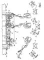
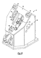
- FIG. 2 is an elevational view illustrating a preferred embodiment of the present invention and with parts removed for clarity;
- FIG. 3 is a sectional fragmentary view illustrating the docking of a tool arm with its associated docking station;
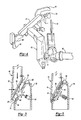
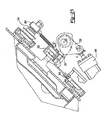
- FIG. 4 is a fragmentary elevational view illustrating one tool arm and a portion of its associated robot;
- FIG. 5 is a view similar to FIG. 3, but illustrating the tool arm in a connected position with its associated docking station;
- FIG. 6 is a view similar to FIG. 4, but illustrating the robotic arm disengaged from its associated tool arm;
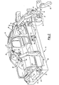
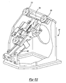
- FIG. 7 is a diagrammatic end view illustrating the introduction of the tool arm in contact with the body to be framed, and its final positioning on the docking station;
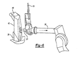
- FIG. 8 is an exploded view illustrating a preferred coupling between the robotic arm and the tool arm;
- FIG. 9 is a perspective view illustrating the coupling assembly, the tool arm being removed for better clarity;
- FIG. 10 is a plan view illustrating a fluid coupling and latch status detection;
- FIG. 11 is a sectional view taken along line 11-11 in FIG. 10, illustrating fluid chamber coupling;
- FIGS. 12-17 are all diagrammatic sectional views illustrating the steps of attachment and detachment of the coupling assembly;
- FIG. 18 is an elevational view illustrating a preferred docking station;
- FIGS. 19-22 are all fragmentary side sectional views illustrating the steps in the attachment of the tool arm to the docking station;
- FIGS. 23-24 are elevational views illustrating a T-shaped brace in the tool arm;
- FIG. 25 is an elevational view of the tool arm with parts removed for clarity;
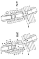
- FIG. 26 is an exploded view illustrating a fluid connector between the tool arm and the docking station;
- FIGS. 27-30 are all side fragmentary sectional longitudinal views illustrating the fluid connection of one fluid connector between the tool arm and the docking station;
- FIG. 31 is an elevational view of the piston bearing portion of the fluid coupling; and
- FIG. 32 is an isometric side view of the docking station with parts removed for clarity.
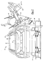
- With reference first to FIG. 1, a preferred embodiment of the
automotive framing system 10 of the present invention is shown for use with a manufacturing line for automotive vehicles. As used in this patent, the term "framing system" encompasses not only the vehicle frame of an automotive vehicle, but also any application where accurate positioning of two or more body components is desired. For example, such a framing system would also include fender setting, roof setting, door setting, as well as other vehicle body components than the vehicle frame. Anelongated conveyor 12, illustrated only diagrammatically, sequentially conveys automotivebody vehicle carriers 14 to anassembly station 16. Any conventional type ofconveyor 12 may be utilized to convey thevehicle carrier 14 to theassembly station 16. - As best shown in FIG. 2, each
vehicle body carrier 14 supports abody preassembly 18 comprising a plurality ofbody vehicle components 20. Thebody vehicle components 20 are only loosely fastened together in their approximate final assembly position by restraining tags, also known as toy tabs, or other conventional means (not shown). Furthermore, thevehicle body carrier 14 is conventionally known as a skid or a geometry pallet in the automotive industry. - With reference now particularly to FIG. 2, the
assembly station 16 is shown in greater detail and comprises a pair of spaced-apartframe members 22 which extend along opposite sides of thevehicle body carrier 14 and thus along opposite sides of thebody preassembly 18. Preferably,crossbeams 24 extend laterally between theframe members 22 to lock theframe members 22 together in a predetermined fixed position. - Still referring to FIG. 2, at least two and preferably three or four
docking stations 26 are provided along each side of theassembly station 16. Eachdocking station 26 is fixedly secured to theframe members 22 so that the position of eachdocking station 26 is fixed relative to theframe member 22 and thus relative to theassembly station 16. - As best shown in FIGS. 2 and 3, each
docking station 26 includes at least one and preferably threelocator pins 28 so that eachlocator pin 28 is positioned at an apex of atriangular surface 30, preferably oriented at 45 degrees from the horizontal on thedocking station 26. As best shown in FIG. 3, eachlocator pin 28 is preferably frusto-conical in shape with a preferred conicity angle of 90 degrees, and thepins 28 are fixedly secured to their associateddocking stations 26. - Each
docking station 26 also includes a media quick coupling 58 (FIGS. 3 and 5) which provides pressurized air and electric signals to the associated clamp arm in order to energize the framing clamps 64 as well as other air cylinder or proximity switches. - With reference now particularly to FIGS. 2 and 4, the framing system further includes a plurality of
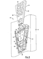
tool arms 40 which, as will be shortly described, selectively clamp thevehicle body components 20 together at a predetermined position relative to each other prior to final assembly. It will be understood, of course, that the precise configuration of eachtool arm 40 will vary depending upon the type of vehicle assembled at theassembly station 16. Consequently, thetool arms 40 illustrated in the drawing are for illustration purposes only. - With reference then to FIGS. 2-4, the
tool arm 40 includes amain body 42 which is constructed of any rigid but light material, such as ribbed thin-walled steel, aluminum or magnesium alloy. A locating surface 44 (FIG. 3) at one end of thetool arm body 42 includes at least one and preferably three locatingsockets 46. The locatingsockets 46 are complementary in shape and number to the locating pins 28. Furthermore, the locatingsockets 46 are positioned on thesurface 44 of thetool arm 40 such that onesocket 46 corresponds to and is aligned with one locatingpin 28 on thedocking station 26. Preferably, the shape of the tool armmain body 42 will have a tetrahedral profile, with a triangular basis matching the locating socket outer pattern. - A robotic arm 50 (FIG. 4) of a robot 52 (FIG. 1) is associated with each
tool arm 40. Furthermore, therobotic arm 50 is selectively secured to its associatedtool arm 40 by a conventionalrobotic coupling 51 so that therobotic arm 50 moves its associatedtool arm 40 between retracted a vehicle loading position and an assembly position. In the vehicle loading position, therobotic arm 50 moves its associatedtool arm 40 laterally outwardly from theassembly station 16 to enable a new body preassembly to be moved into the assembly station. Conversely, in its assembly position, therobotic arm 50 selectively moves its associatedtool arm 40 so that the reference blocks 60, e.g. locating pins, supported by the tool arm enter in contact with their matching surfaces onto the body shell, and then the locatingsockets 46 engage the locating pins 28 as shown in FIG. 5. Aconventional clamp assembly 54 mounted to thedocking station 26 then engages aclamp pin 56 on thetool arm 40 to detachably lock thetool arm 40 to its associateddocking station 26 at a predetermined and fixed position relative to the assemblystation frame members 22. Thereafter, therobotic arm 50 disengages from its associatedtool arm 40 by unlocking therobotic coupling 51 as shown in FIG. 6. - Referring now particularly to FIGS. 2 and 4, at least one, and more typically two or more, framing clamps 64 are secured to each
tool arm 40. These framing clamps 64, once therobotic arm 50 has positioned the reference blocks 60 of its associatedtool arm 40 onto the body shell, and its associatedtool arm 40 on thedocking station 26, engage across clampingsurfaces 62 on thebody components 20. Upon activation of the framing clamps 64, the framing clamps 64 secure thebody components 18 against thereference block 60 at a predetermined position relative to the assemblystation frame member 22 and thus relative to each other. When all of the framing clamps 64 engage their respective clamping surfaces on thebody components 20, thebody preassembly 18 is ready to be secured or welded together. - As best shown in FIG. 6, after the
robotic arm 50 has positioned its associatedtool arm 40 at its associateddocking station 26, and once the docking station lock 54 (FIG. 5) is engaged, therobotic arm 50 disengages from its associatedtool arm body 42 by unlocking therobotic coupling 52. Thereafter, awelding gun 70 attached to therobotic arm 50 is then manipulated by therobotic arm 50 into thebody preassembly 18. Upon activation of thewelding gun 70, thewelding gun 70 secures thebody components 20 together thus completing the automotive body assembly. - It will be understood, of course, that although the
body components 20 are typically secured together by welding, other types of attaching means may alternatively be used without deviation from either the scope or spirit of the present invention. - After the
vehicle body components 12 have been welded or otherwise secured together by therobots 50 manipulating thewelding guns 70 or other attachment means, eachrobotic arm 50 then reengages with its associatedtool arm 40 by locking thetool arm 40 to therobotic arm 50 by thecoupling 51 as shown in FIG. 4. In the meantime, all the framing clamps 64 are released. Thereafter, the tool arm clamp assembly 54 (FIG. 5) is actuated to its unlocked position thus enabling thetool arm 40 to disengage from its associateddocking station 26. The framing clamps 64 are also opened, so that eachrobotic arm 50 is then able to move its associatedtool arm 40 from the assembly position to a vehicle loading position at a position spaced laterally outwardly from the framingstation 16. In the case of a new vehicle model to be framed, the robot will drop theprevious tool arm 40 in its tool arm storage 27 (FIG. 1) and pick a new one suitable for the new model. - After the
tool arms 40 are moved to their vehicle loading position, the now assembled automotive body is moved by theconveyor 12 out of theassembly station 16, anew vehicle carrier 14 with itsbody preassembly 18 is moved into theassembly station 16 and the above process is repeated. - With reference now to FIG. 7, an important advantage of the present invention is that each
robotic arm 50 is able to manipulate portions of its associatedtool arm 40 into the interior of thebody preassembly 18 so that stationary reference blocks 60 are positioned closely adjacent the reference surfaces on thebody components 20. For example, as shown in FIG. 7, therobotic arm 50 may be used to manipulate its associatedtool arm 40 to move sections of thetool arm 40 through relativelysmall openings 68 of thebody preassembly 18 prior to attaching thetool arm 40 to itsdocking station 26 as shown in solid line. This, in turn, permits inexpensive and accuratestationary reference block 60 and rapid acting clamps 64 to be used to secure thebody components 20 together at their desired position prior to assembly. - A still further advantage of the present invention is that different vehicle body styles may be assembled at the
same assembly station 16 and using thesame robots 52. More specifically, since therobotic arms 50 of therobots 52 selectively engage and disengage from their associatedtool arms 40, therobotic arms 50 may also selectively engagedifferent tool arms 40 in order to accommodate different automotive body styles. As such, by merely selectively engaging and disengaging withdifferent tool arms 40, different body styles may be easily accommodated and assembled at thesame assembly station 16. Because of the modularity of the tool set used, if the design of two different bodies presents some commonality, such as a front block, only a fraction of the tool set can be changed to frame this different body. - With reference now to FIGS. 8-11, a preferred
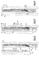
robotic coupling 151 is illustrated for selectively coupling the tool arm 40 (FIG. 11) to therobotic arm 50. Therobotic coupling 151 includes aplate 152 having twoends sides plate 152 is secured to thetool arm 40 in any conventional fashion, such as by bolts or other threaded fasteners. - With reference now particularly to FIGS. 8 and 11, the
sides plate 152 taper away from each other from thebottom end 156 and to thetop end 154 of theplate 152. Furthermore, as best shown in FIG. 11, anupper surface sides - Still referring to FIGS. 8 and 11, the
robotic coupling 51 further includes acoupler 162 which is secured to therobotic arm 50, either directly or through a tool attached to this robotic arm, in any conventional fashion, such as by bolts. Thecoupler 162 includes a top 164, bottom 168 andsides cavity 174 which is complementary in shape to theplate 154. Consequently, thesides coupler 162 taper outwardly from the bottom 168 and to its top 164. Additionally, the upper surfaces of thesides - With reference now particularly to FIGS. 8 and 9, the top 164 of the
coupler 162 is open so that theplate 152 may be flatly positioned against abottom 178 of thecoupler 162 with theends coupler 162 andplate 152 spaced apart from each other. In this position, theplate 152 andcoupler 162 are in a disengaged position in which thecoupler 162 with its attachedrobotic arm 50 may be moved independently of theplate 152 with its attached tool arm 140. - Conversely, as the
ends coupler 162 andplate 152 are moved together as shown in FIGS. 9 and 11, theplate 152 nests within thecavity 174. In this engaged position thesides plate 152 dovetail with thesides coupler 162 to lock theplate 152 andcoupler 162 together against relative movement. With theplate 152 andcoupler 162 in the position illustrated in FIG. 9, therobotic arm 50 may be used to manipulate thetool arm 40 in the desired fashion. - With reference now particularly to FIGS. 8, 16 and 17, a
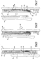
latch assembly 190 is contained within thecoupler 162 for selectively locking thecoupler 162 andplate 152 together when theplate 152 andcoupler 162 are in their engaged position (FIG. 9). Thislatch assembly 190 includes alatch bar 192 which is pivotally mounted by apin 200 to thecoupler 162. Anactuator plate 194 is mounted to thecoupler 162 and has anend 216 pivotally connected to thelatch bar 192 so that thelatch bar 192 pivots about thepin 200 in unison with movement of theactuator plate 194. Theactuator plate 194 is movable between an extended position, illustrated in FIG. 17, and a retracted position illustrated in FIG. 16. In its extended position, thelatch bar 192 protrudes outwardly from thebottom 178 of thecoupler 162 and conversely, in its retracted position (FIG. 14), thelatch bar 192 is generally flush with thebottom 190 of thecoupler 162. - As best shown in FIGS. 10 and 12, a pair of compression springs 202 are entrapped in a state of compression between the
coupler 162 and thelatch bar 192. Thesprings 202 urge thelatch bar 192 towards its extended position illustrated in FIG. 12. - With reference now to FIGS. 10-12, a
resilient diaphragm 204 is attached to thecoupler 162 by anannular seal ring 206 thus forming afluid chamber 208 between thediaphragm 204 and thecoupler 162. Thisfluid chamber 208, in turn, is fluidly accessible through a fluid port 210 (FIG. 11). - As best shown in FIGS. 10 and 11, the
diaphragm 204, together with itsseal ring 206, preferably includes substantially diametrically opposed, upwardly extendingwings 212. These wings facilitate access to thechamber 208 by thefluid port 210 while still retaining a very thin profile for thecoupler 162. - With reference now to FIG. 12, when the
fluid chamber 208 is in its uninflated position, thesprings 202 maintain thelatch bar 192 in its extended position. Conversely, when thefluid chamber 208 is inflated, typically by pneumatic pressure as shown in FIG. 16, thediaphragm 204 moves theactuator plate 194 outwardly relative to thediaphragm 204 thus pivoting thelatch bar 192 from its extended to its retracted position against the force of thesprings 202. - With reference now to FIGS. 12-17, the operation of the
robotic coupling 151 will now be described. With reference first to FIG. 12 and assuming that thecoupler 162 andplate 152 are disengaged from each other, therobotic arm 50 moves thecoupler 162 in the direction ofarrow 220 toward theplate 152. At this time, theend 156 of theplate 152 is spaced upwardly from theend 168 of thecoupler 162 so that theplate 152 may be flatly positioned against thebottom 174 of thecoupler 162 as shown in FIG. 13. Furthermore, as thecoupler 162 is moved from the position shown in FIG. 12 and to the position shown in FIG. 13, theplate 152 engages the outwardly protrudinglatch bar 192 and pivots thelatch bar 192 from its extended position shown in FIG. 12 and to its retracted position shown in FIG. 13. - With reference now to FIGS. 13 and 14, after the
robotic arm 50 has positioned the coupler into flat engagement with theplate 152 as shown in FIG. 13, therobotic arm 50 moves thecoupler 162 in the direction ofarrow 222, i.e. in an end-to-end direction relative to both thecoupler 162 andplate 152, to the engaged position illustrated in FIG. 14. At this time, the sides of thecoupler 162 andplate 152 abut, or nearly abut, together thus locking theplate 152 andcoupler 162 together. Simultaneously, thelatch bar 192 registers with anopening 224 in theplate 152 and the force of thesprings 202 return thelatch bar 192 to its extended position (FIG. 14). In doing so, thelatch bar 192 is positioned within theopening 224 thus locking theplate 152 andcoupler 162 together against end-to-end movement while the dovetail nesting of the sides of thecoupler 162 andplate 152 locks thecoupler 162 andplate 152 together against movement in the other axis. Once the tool arm is released from its docking station, therobot 50 may then be used to manipulate thetool arm 40 to the position desired. - With reference now to FIGS. 15 and 16, once the
tool arm 40 is positioned at the desired position, thechamber 208 is pressurized thus moving theactuator plate 194 to an extended position and pivoting thelatch bar 192 to its retracted position as shown in FIG. 15. With thelatch bar 192 in its retracted position, therobotic arm 50 then moves thecoupler 162 in a downwardly end-to-end movement in the direction indicated byarrow 230 thus disengaging theplate 152 from thecoupler 162. Therobotic arm 50 then moves thecoupler 162 to a completely disengaged position from theplate 152 as shown in FIG. 17. Additionally, thechamber 208 is depressurized in FIG. 17 thus returning thelatch bar 192 to its extended position under the force of thesprings 202. - With reference now to FIG. 9, in order to enable the emergency release of the
plate 152 from thecoupler 162, e.g. in the event of failure of the diaphragm, anopening 232 is provided through thecoupler 162. This opening is aligned with an area below theactuator plate 194 adjacent thelatch bar 192. Consequently, insertion of a tool, such as a screwdriver, enables thelatch bar 192 to be mechanically pivoted by the tool to its retracted position thus releasing theplate 152 from thecoupler 162. - The robotic coupling illustrated in FIGS. 8-17 enjoys many advantages over the previously known robotic couplings. Perhaps most importantly, the
robotic coupling 151 is not only lightweight, but also enjoys a very thin profile since both thecoupler 162 as well as theplate 152 may be thin in thickness, e.g. approximately one inch. Furthermore, the present invention provides a secure attachment between theplate 152 and thecoupler 162 due to the dovetail connection between theplate 152 andcoupler 162. In addition, only limited movement of therobotic arm 50 is required in order to move theplate 152 andcoupler 162 between their engaged and disengaged positions. - With reference now to FIGS. 18 and 32, a still further preferred embodiment of a docking station 26' in which, as before, the docking station 26' includes a
housing 299 havingdocking surface 300 having three frusto-conical locator pins 302 positioned on thesurface 30 in a triangular pattern. A T-shapedbrace 304 is contained within the docking station 26' so that each end of the T-shapedbrace 304 is aligned with a center of one of the locator pins 302. As such, all compressive force exerted against the locator pins 302 is transmitted solely to the T-shapedbrace 304 rather than the housing for the docking station 26'. - As best shown in FIG. 23, the
tool arm 40 includes threelocator sockets 306 mounted on adocking surface 308. Theselocator sockets 306 are complementary in shape to the locator pins 302 on the docking station 26' (FIG. 18). Additionally, thesockets 306 are mounted on thedocking surface 308 such that one locator socket 306 s aligned with onelocator pin 302 when thetool arm 40 is docked on the docking station 26'. - As best shown in FIGS. 21, 23 and 24, a T-shaped
brace 314 is contained within thetool arm 40 so that each end 316 (FIG. 23) is aligned with and connected to a center of eachlocator socket 306. Preferably, aBelleville washer 318 is disposed between at least oneend 316 of the T-shapedbrace 304 and its associatedlocator pin 302. - As best shown in FIG. 21, a
retainer 320 having aretainer opening 322 is secured to the T-shapedbrace 314. Consequently, all axial forces exerted on theretainer 320 are transmitted directly through thelocator sockets 306 and locator pins 302 and their associated T-shapedbraces - With reference now to FIG. 19, an
actuator assembly 330 is contained within thedocking station 299 for selectively locking thetool holder 40 and docking station 26' together. The actuator assembly includes ahook 332 which is pivotally mounted to aneccentric shaft 334 which in turn is pivotally mounted to the T-shapedbrace 304. - A pair of
cam plates 336 are positioned along opposite sides of thehook 332. Thecam plates 336 are secured to theshaft 334 by a key 337 so that thecam plates 336 pivot in unison with theeccentric shaft 334. - A
linear actuator 340 pivots both thecam plates 336 and hook 332 between an unlocked position, illustrated in FIG. 19, and the locked position, illustrated in FIG. 22 in a fashion to be shortly described. In its unlocked position (FIG. 19), thelinear actuator 340 is in its extended position. In this position, adowel 342 extending between thecam plates 336 engages astop 344 on thehook 332. Thedowel pin 342 maintains thehook 332 in its unlocked position against the force of one or more tension springs 348. - With reference now to FIG. 20, with the
linear actuator 340 in its fully extended position and thehook 332 in its fully retracted position, the robot is used to manipulate and position thetool arm 40 on top of the docking station 26' such that the threelocator sockets 306 on thetool arm 40 engage with the threelocator pins 302 on the docking station 26'. It will be understood, of course, that the location of the locator sockets and locator pins may be reversed, i.e. the locator sockets are positioned on the docking station 26' while the locator pins are positioned on thetool arm 40. Indeed, it is possible for a mixture of locator sockets and locator pins to be provided on both the docking station 26' andtool arm 40 as long as one locator socket engages each of the locator pins. - With reference now to FIG. 21, after the
tool arm 40 is positioned in its docking position on the docking station 26', theactuator 340 is partially retracted to the position shown in FIG. 21. In doing so, the tension springs 348 pivot thehook 332 to the position shown in FIG. 21 in which the hook extends through theopening 322 in theretainer 320 thus locking thetool arm 40 to the docking station 26'. - Thereafter, the
linear actuator 340 is further retracted to the final position illustrated in FIG. 22 and, in doing so, moves thehook 332 in a direction normal to thetool arm 40 as indicated byarrow 350 due to the eccentricity of theshaft 334. This normal movement of thehook 332 thus compresses thetool arm 40 and docking station 26' together through the locator pins 302 andsockets 306. - As previously described, the
retainer 320 is mounted directly to the T-shapedbrace 314 while, similarly, theeccentric shaft 334 is rotatably mounted to the T-shapedbrace 304 contained within the docking station 26'. Consequently, the entire tensile force exerted between thehook 332 and theretainer 320 when theactuator 340 is moved to its final retracted position shown in FIG. 22 is transmitted solely through the T-shapedmembers braces tool holder 40 are isolated from any deflection or distortion caused by the tensile force between thehook 332 andretainer 320 and the corresponding offsetting compressive force between the locator pins and sockets. Instead, any deflection or distortion caused by the compressive force between thehook 332 andretainer 320 is borne entirely by the T-shapedbraces - With reference now to FIG. 25, when the
linear actuator 340 is moved to its most retracted position, thecam plate 336 engages acam follower 337 on anelectrical connection box 352 and pivots thebox 352 from a retracted position, illustrated in FIG. 21, to an extended position, illustrated in FIG. 25 about apivot axis 354. Theelectrical box 352 contains one or more spring loaded electrical contacts and is conventional in construction. Thebox 336, when in its extended position (FIG. 22), provides one or more electrical connections between the docking stations 26' and thetool holder 40. - As can be seen from the foregoing, the attachment between the docking station 26' and the
tool support 40 not only eliminates distortion of both thetool support 40 and docking station 26' by transferring any such distortion to the T-shapedbraces - In many situations, it is also necessary to provide fluid power from the docking station 26' to the
tool support 40. Consequently, as best shown in FIGS. 18 and 25, afluid port plate 360 is mounted on thedocking surface 300 of the docking station 26'. Thisport plate 360 includes one or morefluid ports 362. - With reference now particularly to FIG. 26, a
fluid coupling assembly 364 is also connected to thetool holder 40. Thefluid coupling assembly 364 includes ahousing 366 having one or morefluid lines 368 extending outwardly from the housing. - With reference now to FIG. 27, one
fluid line 368 is there shown in greater detail and includes abore 370 formed through thehousing 366 and threaded at itsupper end 372. A pair of alignedbushings bore 370 and an O-ring 376 is positioned between thebushings bushing 375, preferably the inner one submitted to air chamber pressure, also includes anotch 378 to facilitate removal and replacement of the O-ring 376 when required. - With reference again to FIG. 27, a
tubular piston 380 is axially slidably mounted within thebushings lip 382 at its upper end. Thislip 382 abuts against the top of thebushing 374 and retains thepiston 380 within thebushings ring 376 fluidly seals thepiston 380 to thebushings housing 366. - A
tubular plug 384 threadably engages the threadedend 372 of the housing bore 370 and, in turn, includes an internally threaded bore 386 aligned with thepiston 380. Aconventional fluid coupling 388 is then threadably connected to the threadedplug bore 384. - A
lightweight compression spring 390 is compressed between theplug 384 and anannular abutment surface 392 on thepiston 380. Additionally, an O-ring 396 is attached to and protrudes outwardly from the free end of thepiston 380. - With reference then to FIGS. 27 and 28, as the
robotic arm 50 moves thetool holder 40 into its docking position from the position shown in FIG. 27 to the position shown in FIG. 28 and finally to the position shown in FIG. 29, the O-ring 396 engages theplate 360 around thefluid port 362 compressing thepiston 380 against the force of thecompression spring 390 as required. When thetool arm 40 reaches its final docking position (FIG. 29), thepiston 380 is aligned with theport 362. In this position, thecompression spring 390 maintains contact of the O-ring 396 with theport plate 360. - Thereafter, as shown in FIG. 30, upon pressurization of the
port 362, the fluid pressure causes thepiston 380 to shift axially in the direction ofarrow 398 toward theport plate 360. The amount of axial displacement of thepiston 380 from the position shown in FIG. 28 prior to pressurization and to the position shown in FIG. 29 after pressurization is exaggerated in the drawing for added clarity. In any event, the axial displacement of thepiston 380 in the direction ofarrow 398 compresses the O-ring 396 thus establishing the fluid seal between thepiston 380 and thefluid port 362. - A primary advantage of the fluid coupling illustrated in FIGS. 26-29 is that the direction of approach between the
tool support 40 anddocking station 26 may be at an angle of up to 90 degrees off center and requires only minimal axial displacement between the tool arm and the docking station 26' once thepistons 380 andfluid port 362 are aligned. This, in turn, allows greater flexibility in the design of the tooling attached to the tool arm that is required for the previously known fluid couplings which require extended axial movement between the tool arm and the docking station in order to achieve the necessary fluid connection. - Having described my invention, many modifications thereto will become apparent to those skilled in the art to which it pertains without deviation from the spirit of the invention as defined by the scope of the appended claims.
Claims (23)
- A coupling assembly for use with a robotic arm and a tool arm comprising:a plate mounted to the tool arm, said plate having spaced-apart ends and spaced-apart sides which extend between said plate ends and taper outwardly from each other,a coupler mounted to the robotic arm, said coupler having a cavity with sides complementary in shape to said plate,wherein with said plate positioned within said coupler cavity, said plate is movable in an end-to-end direction between an engaged position in which said coupler and said plate are mechanically locked together and a disengaged position in which said coupler and said plate are mechanically unlocked from each other,a latch assembly mounted to said coupler and movable between a locked position in which said latch locks said coupler and said plate in said engaged position and an unlocked position in which said coupler and said plate are freely movable from said engaged and to said disengaged position.
- The invention as defined in claim 1 wherein said plate includes an opening and wherein said latch assembly comprises a latch bar pivotally mounted to said coupler between an extended position in which said latch bar extends into said plate opening when said plate and coupler are in said extended position to thereby prevent movement of said coupler and said plate from said engaged position to said disengaged position, and a retracted position in which said latch bar is retracted from said plate opening.
- The invention as defined in claim 2 and comprising a spring which resiliently urges said latch bar toward said extended position.
- The invention as defined in claim 3 and comprising an actuator plate mounted to said coupler and movable between a first position and a second position, said actuator plate being connected to said latch bar so that it pivots between said extended and said retracted positions in unison as said actuator plate moves between said first and second positions, respectively.
- The invention as defined in claim 4 wherein the actuator plate acts as a stroke amplifier, converting the small stroke/heavy force developed by the pneumatic actuator into a longer stroke at lower retraction force for the latch.
- The invention as defined in claim 5 and comprising a fluid-operated diaphragm mounted to said coupler in abutment with said actuator so that, upon inflation, said diaphragm moves said actuator from said first position and to said second position sufficient to fully retract the latch.
- The invention as defined in claim 2 wherein said coupler includes a manual release opening open to said latch assembly.
- The invention as defined in claim 1 wherein said sides of said plate taper toward each other along a top surface of said plate and wherein said coupler includes surfaces complementary to said tapered top surface of said plate.
- The invention as defined in claim 8 wherein said tapered plate and coupler dovetail together, providing a vertical sliding compliance for the robot wrist when loading the arm tool onto its docking station.
- A docking apparatus comprising:a docking station having a docking surface,a tool arm having a docking surface,at least three locator pins mounted on one or both of said docking surfaces,at least three locator sockets complementary in shape to said locator pins mounted on one or both of said docking surfaces, said locator pins and said locator sockets being positioned so that, when said tool arm is moved to a docking position relative to said docking station, each locator pin on each docking surface registers with a locator socket on the other docking surface,an actuator assembly mounted to said docking station and movable between an unlocked position in which said docking station and said tool arm are separable from each other and a locked position in which said docking station and said tool arm are secured against movement relative to each other.
- The invention as defined in claim 10 wherein said locator pin and socket have preferably a 90-degree angle frusto-conical shape, allowing a final approach of the tool arm by the robot anyway inside of a 90-degree cone.
- The invention as defined in claim 10 wherein said actuator assembly comprises a retainer attached to said tool support and protruding outwardly from said tool arm docking surface, and a hook mounted to said base and movable between a locked position in which said hook disengages from said retainer and a locked position in which said hook engages said retainer.
- The invention as defined in claim 12 wherein said locator pins and locator sockets are arranged in a triangle on said docking surfaces and wherein said retainer and said hook are positioned in the center of said triangle on their respective docking surface.
- The invention as defined in claim 13 and comprising a first T-shaped brace positioned within said tool support and having its ends aligned with and secured to a center of each locator pin or locator socket on said tool arm docking surface, said retainer being secured to said T-shaped brace.
- The invention as defined in claim 14 and comprising at least one compressive member sandwiched between one end of said brace, and its associated locator pin or socket supporting structure.
- The invention as defined in claim 14 and comprising a second T-shaped brace positioned within said docking station and having its ends aligned with and secured to a center of each locator pin or locator socket on said base docking surface, said hook being secured to said T-shaped brace.
- The invention as defined in claim 12 and comprising an eccentric shaft, said hook being pivotally mounted to said eccentric shaft, a cam attached to said shaft, and a linear actuator attached to said cam so that said linear actuator pivots said cam and shaft as said linear actuator moves from a first to a second position, wherein said hook engages said retainer at a midpoint of the linear actuator movement from said first to said second position so that further movement of said linear actuator to said second position retracts said hook away from said retainer and imposes a tensile force on said hook and said retainer.
- The invention as defined in claim 17 and comprising an array of electrical connectors pivotally connected to said base, wherein said cam pivots said electrical connector array outwardly from said docking station docking surface when said linear actuator moves to said second position.
- The invention as defined in claim 17 and comprising a spring which urges said hook toward said locked position, a dowel attached to said cam, and said hook having a stop surface which abuts against said dowel so that said cam retains said hook in said unlocked position against the force of said spring when said linear actuator is in said first position.
- The invention as defined in claim 18 wherein said cam comprises a pair of cam plates, said hook being sandwiched between said cam plates.
- The invention as defined in claim 10 and comprising a plate having a fluid port on said docking station, a fluid connector mounted on said tool arm which is aligned with said fluid port when said docking station and said tool arm are in said docking position.
- The invention as defined in claim 21 wherein said fluid connector comprises a bore, a tubular piston mounted in said bore and movable between a retracted and extended position in which a free end of said piston protrudes outwardly from said tool support docking surface, a spring which urges said piston toward said extended position, and a seal mounted to said free end of said piston and adapted to engage said plate.
- The invention as defined in claim 22 and comprising a seal disposed between an outer surface of said piston and said bore so that, upon pressurization of said fluid port, said fluid pressure generates an outward force on said piston to thereby compress said first seal against said plate.
Applications Claiming Priority (1)
| Application Number | Priority Date | Filing Date | Title |
|---|---|---|---|
| US11/230,715 US7685699B2 (en) | 2003-09-23 | 2005-09-20 | Docking apparatus |
Publications (3)
| Publication Number | Publication Date |
|---|---|
| EP1764291A2 true EP1764291A2 (en) | 2007-03-21 |
| EP1764291A3 EP1764291A3 (en) | 2008-05-07 |
| EP1764291B1 EP1764291B1 (en) | 2010-04-14 |
Family
ID=37403486
Family Applications (1)
| Application Number | Title | Priority Date | Filing Date |
|---|---|---|---|
| EP06019683A Not-in-force EP1764291B1 (en) | 2005-09-20 | 2006-09-20 | Automotive vehicle framing system |
Country Status (4)
| Country | Link |
|---|---|
| US (1) | US7685699B2 (en) |
| EP (1) | EP1764291B1 (en) |
| DE (1) | DE602006013559D1 (en) |
| ES (1) | ES2344596T3 (en) |
Cited By (4)
| Publication number | Priority date | Publication date | Assignee | Title |
|---|---|---|---|---|
| WO2008134765A2 (en) * | 2007-04-30 | 2008-11-06 | Frank's International, Inc. | Method and apparatus to position and protect control lines being coupled to a pipe string on a rig |
| DE102012023770A1 (en) * | 2012-12-05 | 2014-06-05 | GM Global Technology Operations LLC (n. d. Ges. d. Staates Delaware) | Mounting device for mounting a retaining element for attachments to a motor vehicle and method for mounting attachments to a motor vehicle |
| US9598914B2 (en) | 2007-04-30 | 2017-03-21 | Frank's International, Llc | Method and apparatus to position and protect control lines being coupled to a pipe string on a rig |
| US9938780B2 (en) | 2007-04-30 | 2018-04-10 | Frank's International, Llc | Method and apparatus to position and protect control lines being coupled to a pipe string on a rig |
Families Citing this family (16)
| Publication number | Priority date | Publication date | Assignee | Title |
|---|---|---|---|---|
| DE102006035025A1 (en) * | 2006-07-28 | 2008-04-30 | GM Global Technology Operations, Inc., Detroit | Strut positioning device |
| US7857222B2 (en) | 2007-08-16 | 2010-12-28 | Hand Held Products, Inc. | Data collection system having EIR terminal interface node |
| US9497092B2 (en) | 2009-12-08 | 2016-11-15 | Hand Held Products, Inc. | Remote device management interface |
| JP5423441B2 (en) * | 2010-02-03 | 2014-02-19 | 株式会社安川電機 | Work system, robot apparatus, and manufacturing method of machine product |
| KR101172308B1 (en) * | 2010-09-06 | 2012-08-07 | 현대자동차주식회사 | Gripper for door of vehicle |
| US8621123B2 (en) | 2011-10-06 | 2013-12-31 | Honeywell International Inc. | Device management using virtual interfaces |
| US8539123B2 (en) | 2011-10-06 | 2013-09-17 | Honeywell International, Inc. | Device management using a dedicated management interface |
| CN102500983B (en) * | 2011-11-11 | 2014-08-06 | 郑州宇通客车股份有限公司 | Rear axle rear segment sub-assembly frame welding mould of full-bearing passenger car |
| KR101326835B1 (en) * | 2011-12-06 | 2013-11-07 | 현대자동차주식회사 | Side positioning device of system for assembling body panel |
| KR101449329B1 (en) * | 2013-09-09 | 2014-10-15 | 현대자동차주식회사 | Jig device for trunk lid |
| US10559223B2 (en) * | 2014-09-08 | 2020-02-11 | Under Armour, Inc. | Food description processing methods and apparatuses |
| JP6092909B2 (en) * | 2015-02-10 | 2017-03-08 | 富士重工業株式会社 | Body manufacturing equipment |
| JP6403822B2 (en) * | 2017-03-17 | 2018-10-10 | 本田技研工業株式会社 | Panel gripping apparatus and panel gripping method |
| CN110153611B (en) * | 2019-04-30 | 2024-06-11 | 重庆山朕科技发展有限公司 | Welding fixture based on front anti-collision cross beam and trailer sleeve |
| CN115255857B (en) * | 2022-08-03 | 2024-05-03 | 江苏松田电子科技有限公司 | Flexible assembly workstation of both hands arm robot |
| CN116252082B (en) * | 2023-05-16 | 2023-07-07 | 山东轻工职业学院 | Welding device for connecting pipe of electromechanical equipment |
Citations (1)
| Publication number | Priority date | Publication date | Assignee | Title |
|---|---|---|---|---|
| EP1518784A2 (en) | 2003-09-23 | 2005-03-30 | Valiant Corporation | Automotive vehicle framing system |
Family Cites Families (29)
| Publication number | Priority date | Publication date | Assignee | Title |
|---|---|---|---|---|
| US4494687A (en) | 1983-03-21 | 1985-01-22 | Comau S.P.A. | Expanded car body welding assembly system |
| DE3342570C2 (en) | 1983-11-25 | 1986-07-10 | Thyssen Maschinenbau GmbH Nothelfer-Ravensburg, 7980 Ravensburg | Method for fastening a door to a body of a motor vehicle and device for carrying out this method |
| JPS6112474A (en) | 1984-06-26 | 1986-01-20 | Toyota Motor Corp | Vehicle body assembling device |
| FR2627116B1 (en) | 1988-02-17 | 1994-03-25 | Renault Automation | METHOD AND DEVICE FOR INTERLOCATING TOOLS OF A BODY ASSEMBLY MACHINE |
| US5232513A (en) | 1989-06-30 | 1993-08-03 | Suratt Ted L | Engine cleaning processes |
| US5011068A (en) | 1989-12-05 | 1991-04-30 | Progressive Tool & Industries Co. | Automotive body framing system |
| US5251739A (en) | 1991-02-01 | 1993-10-12 | Giddings & Lewis, Inc. | Automatic framing system |
| US5452981A (en) | 1991-03-06 | 1995-09-26 | Leland D. Blatt | Automatic tool changer |
| US5163726A (en) * | 1991-10-15 | 1992-11-17 | Bromma, Inc. | Spreader bar and overheight attachment with automatic latching mechanism |
| US5419352A (en) | 1993-04-19 | 1995-05-30 | Johnson; Carl W. | Cleaning system and method |
| US5409158A (en) | 1993-07-08 | 1995-04-25 | Progressive Tool & Industries Company | Automobile framing system |
| IT1261269B (en) | 1993-09-20 | 1996-05-09 | Comau Spa | POINT WELDING DEVICE FOR STRUCTURES CONSISTING OF PRINTED SHEET ELEMENTS, IN PARTICULAR MOTOR VEHICLE BODIES |
| FR2711957B1 (en) | 1993-11-03 | 1996-01-05 | Renault Automation | Assembly method and device for body parts. |
| DE4418755A1 (en) | 1994-05-28 | 1995-11-30 | Kuka Schweissanlagen & Roboter | Process and device for the mfr. of vehicle bodies within framed cages |
| US5560535A (en) | 1995-03-30 | 1996-10-01 | Western Atlas, Inc. | Flexible body framing system |
| IT1288733B1 (en) | 1996-10-08 | 1998-09-24 | Comau Spa | DEVICE FOR POINT WELDING OF STRUCTURES CONSISTING OF METALLIC ELEMENTS, IN PARTICULAR BODIES OF MOTOR VEHICLES OR THEIR |
| FI112334B (en) | 1997-04-08 | 2003-11-28 | Abb Research Ltd | Procedure and arrangement for assembly of car body |
| EP0927598A1 (en) | 1997-12-18 | 1999-07-07 | COMAU S.p.A. | Device for spot-welding of motor-vehicle bodies or sub-assemblies thereof |
| JP3632413B2 (en) | 1997-12-19 | 2005-03-23 | 豊田工機株式会社 | Flexible production system and control method thereof |
| PT933161E (en) | 1998-02-03 | 2001-09-28 | Comau Spa | DEVICE FOR MOUNTING CAROUSES OF AUTOMOTIVE VEHICLES BY WELDING FOR POINTS |
| DE19820094A1 (en) * | 1998-05-06 | 1999-11-18 | Thyssen Industrie | System for positioning and welding body parts of different types of vehicles |
| FR2779405B1 (en) | 1998-06-09 | 2000-07-13 | Abb Preciflex Systems | PROCESS FOR MAKING AN AUTOMOTIVE BODY |
| FR2799428B1 (en) | 1999-10-11 | 2001-12-21 | Abb Body In White | MEANS OF HOLDING TWO PIECES IN POSITION RELATIVE TO THE OTHER |
| US6493950B1 (en) * | 2000-06-23 | 2002-12-17 | Rolling Razor, L.L.C. | Rolling razor and shaving method |
| US6364817B1 (en) | 2000-09-08 | 2002-04-02 | Unova Ip Corp. | Automotive framing apparatus |
| CA2447504C (en) | 2001-05-16 | 2007-07-31 | Mark A. Savoy | Method and apparatus for assembling exterior automotive vehicle body components onto an automotive vehicle body |
| US20030037432A1 (en) | 2001-08-21 | 2003-02-27 | Mcnamara Jeffrey S. | Automotive body component positioning method and apparatus |
| US6595407B2 (en) | 2001-10-16 | 2003-07-22 | Unova Ip Corp. | Flexible framing station tool gate changing method and apparatus |
| FR2833877B1 (en) | 2001-12-21 | 2004-03-19 | Abb Body In White | MODULAR STRUCTURE FOR HOLDING BODY PIECE |
-
2005
- 2005-09-20 US US11/230,715 patent/US7685699B2/en not_active Expired - Fee Related
-
2006
- 2006-09-20 ES ES06019683T patent/ES2344596T3/en active Active
- 2006-09-20 EP EP06019683A patent/EP1764291B1/en not_active Not-in-force
- 2006-09-20 DE DE602006013559T patent/DE602006013559D1/en active Active
Patent Citations (1)
| Publication number | Priority date | Publication date | Assignee | Title |
|---|---|---|---|---|
| EP1518784A2 (en) | 2003-09-23 | 2005-03-30 | Valiant Corporation | Automotive vehicle framing system |
Cited By (7)
| Publication number | Priority date | Publication date | Assignee | Title |
|---|---|---|---|---|
| WO2008134765A2 (en) * | 2007-04-30 | 2008-11-06 | Frank's International, Inc. | Method and apparatus to position and protect control lines being coupled to a pipe string on a rig |
| WO2008134765A3 (en) * | 2007-04-30 | 2009-02-05 | Frank S Inr Inc | Method and apparatus to position and protect control lines being coupled to a pipe string on a rig |
| EP2392766A1 (en) * | 2007-04-30 | 2011-12-07 | Frank's International, Inc. | Method and apparatus to position and protect control lines being coupled to a pipe string on a rig |
| US8225875B2 (en) | 2007-04-30 | 2012-07-24 | Frank's Casing Crew And Rental Tools, Inc. | Method and apparatus to position and protect control lines being coupled to a pipe string on a rig |
| US9598914B2 (en) | 2007-04-30 | 2017-03-21 | Frank's International, Llc | Method and apparatus to position and protect control lines being coupled to a pipe string on a rig |
| US9938780B2 (en) | 2007-04-30 | 2018-04-10 | Frank's International, Llc | Method and apparatus to position and protect control lines being coupled to a pipe string on a rig |
| DE102012023770A1 (en) * | 2012-12-05 | 2014-06-05 | GM Global Technology Operations LLC (n. d. Ges. d. Staates Delaware) | Mounting device for mounting a retaining element for attachments to a motor vehicle and method for mounting attachments to a motor vehicle |
Also Published As
| Publication number | Publication date |
|---|---|
| US7685699B2 (en) | 2010-03-30 |
| EP1764291A3 (en) | 2008-05-07 |
| ES2344596T3 (en) | 2010-09-01 |
| US20060013646A1 (en) | 2006-01-19 |
| EP1764291B1 (en) | 2010-04-14 |
| DE602006013559D1 (en) | 2010-05-27 |
Similar Documents
| Publication | Publication Date | Title |
|---|---|---|
| US7857539B2 (en) | Automotive vehicle framing system | |
| US7685699B2 (en) | Docking apparatus | |
| US8132801B2 (en) | Positioning and clamping apparatus | |
| CN108500964B (en) | End effector assembly and robotic system having the same | |
| US6687971B2 (en) | Vehicle body transfer machine and method thereof | |
| EP1827769B1 (en) | Handling device and method multiaxial handling and guiding workpieces arranged on a supporting device | |
| CN1059633C (en) | Method and device for assembling bodywork parts | |
| JP5004660B2 (en) | Work clamp device | |
| JPS63306840A (en) | Device and method of setting position of body | |
| CN101506033A (en) | Method, apparatus and plant for manufacturing shell structures | |
| US8046895B2 (en) | System and method for assembling a vehicle body structure | |
| JP7171467B2 (en) | SUPPORT DEVICE FOR PARTS HOLDER AND VEHICLE DOOR REMOVAL DEVICE | |
| US20050035516A1 (en) | Sealed pin locator clamp | |
| CN218802340U (en) | Manipulator tool clamp | |
| WO2006031265A1 (en) | Machining fixture assembly and method including an adaptor | |
| US4872380A (en) | Workpiece positioner for chuck and center machining | |
| CN114258340A (en) | Pneumatic chuck | |
| JPH0413069Y2 (en) | ||
| CN214641883U (en) | Composite material tool clamping device | |
| CN220007616U (en) | Quick-change assembly for screwdriver head and sleeve | |
| CN220971366U (en) | Quick change mechanism for socket wrench | |
| CN220179382U (en) | Quick change mechanical arm quick change device | |
| CN113733161B (en) | Quick interface device of end effector of mechanical arm | |
| CN211784147U (en) | Multifunctional rubber node rigidity test tool | |
| CN220722720U (en) | Car body workpiece carrying equipment |
Legal Events
| Date | Code | Title | Description |
|---|---|---|---|
| PUAI | Public reference made under article 153(3) epc to a published international application that has entered the european phase |
Free format text: ORIGINAL CODE: 0009012 |
|
| AK | Designated contracting states |
Kind code of ref document: A2 Designated state(s): AT BE BG CH CY CZ DE DK EE ES FI FR GB GR HU IE IS IT LI LT LU LV MC NL PL PT RO SE SI SK TR |
|
| AX | Request for extension of the european patent |
Extension state: AL BA HR MK YU |
|
| PUAL | Search report despatched |
Free format text: ORIGINAL CODE: 0009013 |
|
| AK | Designated contracting states |
Kind code of ref document: A3 Designated state(s): AT BE BG CH CY CZ DE DK EE ES FI FR GB GR HU IE IS IT LI LT LU LV MC NL PL PT RO SE SI SK TR |
|
| AX | Request for extension of the european patent |
Extension state: AL BA HR MK RS |
|
| 17P | Request for examination filed |
Effective date: 20081104 |
|
| AKX | Designation fees paid |
Designated state(s): DE ES FR |
|
| 17Q | First examination report despatched |
Effective date: 20081223 |
|
| GRAP | Despatch of communication of intention to grant a patent |
Free format text: ORIGINAL CODE: EPIDOSNIGR1 |
|
| GRAS | Grant fee paid |
Free format text: ORIGINAL CODE: EPIDOSNIGR3 |
|
| GRAA | (expected) grant |
Free format text: ORIGINAL CODE: 0009210 |
|
| AK | Designated contracting states |
Kind code of ref document: B1 Designated state(s): DE ES FR |
|
| REF | Corresponds to: |
Ref document number: 602006013559 Country of ref document: DE Date of ref document: 20100527 Kind code of ref document: P |
|
| REG | Reference to a national code |
Ref country code: ES Ref legal event code: FG2A Ref document number: 2344596 Country of ref document: ES Kind code of ref document: T3 |
|
| PLBE | No opposition filed within time limit |
Free format text: ORIGINAL CODE: 0009261 |
|
| STAA | Information on the status of an ep patent application or granted ep patent |
Free format text: STATUS: NO OPPOSITION FILED WITHIN TIME LIMIT |
|
| 26N | No opposition filed |
Effective date: 20110117 |
|
| REG | Reference to a national code |
Ref country code: FR Ref legal event code: PLFP Year of fee payment: 11 |
|
| REG | Reference to a national code |
Ref country code: FR Ref legal event code: PLFP Year of fee payment: 12 |
|
| PGFP | Annual fee paid to national office [announced via postgrant information from national office to epo] |
Ref country code: FR Payment date: 20170927 Year of fee payment: 12 |
|
| PGFP | Annual fee paid to national office [announced via postgrant information from national office to epo] |
Ref country code: DE Payment date: 20170927 Year of fee payment: 12 |
|
| PGFP | Annual fee paid to national office [announced via postgrant information from national office to epo] |
Ref country code: ES Payment date: 20171002 Year of fee payment: 12 |
|
| REG | Reference to a national code |
Ref country code: DE Ref legal event code: R119 Ref document number: 602006013559 Country of ref document: DE |
|
| PG25 | Lapsed in a contracting state [announced via postgrant information from national office to epo] |
Ref country code: DE Free format text: LAPSE BECAUSE OF NON-PAYMENT OF DUE FEES Effective date: 20190402 |
|
| PG25 | Lapsed in a contracting state [announced via postgrant information from national office to epo] |
Ref country code: FR Free format text: LAPSE BECAUSE OF NON-PAYMENT OF DUE FEES Effective date: 20180930 |
|
| REG | Reference to a national code |
Ref country code: ES Ref legal event code: FD2A Effective date: 20191031 |
|
| PG25 | Lapsed in a contracting state [announced via postgrant information from national office to epo] |
Ref country code: ES Free format text: LAPSE BECAUSE OF NON-PAYMENT OF DUE FEES Effective date: 20180921 |