EP1764271B1 - Mounting component and mounting structure for curtain airbag - Google Patents
Mounting component and mounting structure for curtain airbag Download PDFInfo
- Publication number
- EP1764271B1 EP1764271B1 EP06018970A EP06018970A EP1764271B1 EP 1764271 B1 EP1764271 B1 EP 1764271B1 EP 06018970 A EP06018970 A EP 06018970A EP 06018970 A EP06018970 A EP 06018970A EP 1764271 B1 EP1764271 B1 EP 1764271B1
- Authority
- EP
- European Patent Office
- Prior art keywords
- curtain airbag
- mounting component
- mounting
- base piece
- projecting pieces
- Prior art date
- Legal status (The legal status is an assumption and is not a legal conclusion. Google has not performed a legal analysis and makes no representation as to the accuracy of the status listed.)
- Not-in-force
Links
- 235000021189 garnishes Nutrition 0.000 description 6
- 238000005452 bending Methods 0.000 description 2
- 238000005516 engineering process Methods 0.000 description 2
- 239000007767 bonding agent Substances 0.000 description 1
- 239000004745 nonwoven fabric Substances 0.000 description 1
- 230000001105 regulatory effect Effects 0.000 description 1
- 230000000452 restraining effect Effects 0.000 description 1
- 230000000717 retained effect Effects 0.000 description 1
- 238000009958 sewing Methods 0.000 description 1
Images


Classifications
-
- B—PERFORMING OPERATIONS; TRANSPORTING
- B60—VEHICLES IN GENERAL
- B60R—VEHICLES, VEHICLE FITTINGS, OR VEHICLE PARTS, NOT OTHERWISE PROVIDED FOR
- B60R21/00—Arrangements or fittings on vehicles for protecting or preventing injuries to occupants or pedestrians in case of accidents or other traffic risks
- B60R21/02—Occupant safety arrangements or fittings, e.g. crash pads
- B60R21/16—Inflatable occupant restraints or confinements designed to inflate upon impact or impending impact, e.g. air bags
- B60R21/23—Inflatable members
- B60R21/231—Inflatable members characterised by their shape, construction or spatial configuration
- B60R21/232—Curtain-type airbags deploying mainly in a vertical direction from their top edge
-
- B—PERFORMING OPERATIONS; TRANSPORTING
- B60—VEHICLES IN GENERAL
- B60R—VEHICLES, VEHICLE FITTINGS, OR VEHICLE PARTS, NOT OTHERWISE PROVIDED FOR
- B60R21/00—Arrangements or fittings on vehicles for protecting or preventing injuries to occupants or pedestrians in case of accidents or other traffic risks
- B60R21/02—Occupant safety arrangements or fittings, e.g. crash pads
- B60R21/16—Inflatable occupant restraints or confinements designed to inflate upon impact or impending impact, e.g. air bags
- B60R21/20—Arrangements for storing inflatable members in their non-use or deflated condition; Arrangement or mounting of air bag modules or components
- B60R21/201—Packaging straps or envelopes for inflatable members
-
- B—PERFORMING OPERATIONS; TRANSPORTING
- B60—VEHICLES IN GENERAL
- B60R—VEHICLES, VEHICLE FITTINGS, OR VEHICLE PARTS, NOT OTHERWISE PROVIDED FOR
- B60R21/00—Arrangements or fittings on vehicles for protecting or preventing injuries to occupants or pedestrians in case of accidents or other traffic risks
- B60R21/02—Occupant safety arrangements or fittings, e.g. crash pads
- B60R21/16—Inflatable occupant restraints or confinements designed to inflate upon impact or impending impact, e.g. air bags
- B60R21/20—Arrangements for storing inflatable members in their non-use or deflated condition; Arrangement or mounting of air bag modules or components
- B60R21/213—Arrangements for storing inflatable members in their non-use or deflated condition; Arrangement or mounting of air bag modules or components in vehicle roof frames or pillars
-
- Y—GENERAL TAGGING OF NEW TECHNOLOGICAL DEVELOPMENTS; GENERAL TAGGING OF CROSS-SECTIONAL TECHNOLOGIES SPANNING OVER SEVERAL SECTIONS OF THE IPC; TECHNICAL SUBJECTS COVERED BY FORMER USPC CROSS-REFERENCE ART COLLECTIONS [XRACs] AND DIGESTS
- Y10—TECHNICAL SUBJECTS COVERED BY FORMER USPC
- Y10T—TECHNICAL SUBJECTS COVERED BY FORMER US CLASSIFICATION
- Y10T24/00—Buckles, buttons, clasps, etc.
- Y10T24/44—Clasp, clip, support-clamp, or required component thereof
- Y10T24/44017—Clasp, clip, support-clamp, or required component thereof with specific mounting means for attaching to rigid or semirigid supporting structure or structure-to-be-secured
- Y10T24/44026—Clasp, clip, support-clamp, or required component thereof with specific mounting means for attaching to rigid or semirigid supporting structure or structure-to-be-secured for cooperating with aperture in supporting structure or structure-to-be-secured
Definitions
- the present invention relates to mounting components for mounting curtain airbags on, for example, roof side rails of vehicle bodies, and relates to mounting structures for curtain airbags using the mounting components.
- Patent Document 1 JP-A-2002-53003
- Patent Document 2 JP-A-2002-53005
- folded curtain airbags are disposed along bottom portions of inverted T-shaped (chevron-shaped) mounting components and bound to the mounting components with pieces of tape.
- the mounting components are attached to roof side rails using bolts.
- the lower sides of the folded curtain airbags having the mounting component attached thereto may be pushed upward or toward the vehicle cabin as a result of striking vehicle members such as B-pillar garnishes during mounting of the folded curtain airbags on the roof side rails, and the mounting components may be hidden behind the folded curtain airbags. In such cases, the mounting components are difficult to attach to the roof side rail.
- US 2005/046154 A1 relates to a mounting bracket that may be used to attach an inflatable curtain airbag having a manifold to an interior vehicle surface.
- the side curtain airbag is attached to an inflator that provides in-flation gas to the airbag during an accident.
- the curtain airbag is secured to the vehicle to ensure that the curtain airbag main-tains a preferred position and orientation during deployment as well as during the normal operation of the vehicle.
- one or more mounting brackets are added to mount the curtain airbag to the vehicle.
- the mounting brackets generally comprise two sections or components, namely a base bracket and a retaining clip.
- the retaining clip is attachable to the base bracket which, in turn, contacts and/or is affixed to the vehicle interior.
- the mounting bracket is constructed such that when the retaining clip is attached to the base bracket, the manifold is held between the retaining clip and the base bracket.
- An object of the present invention is to provide a mounting component for a curtain airbag capable of preventing a folded curtain airbag from hiding the mounting component even when the folded curtain airbag strikes a B-pillar garnish or the like and thus facilitating efficient mounting of the folded curtain airbag, and to provide a mounting structure for a curtain airbag using this mounting component.
- the upward movement of the folded curtain airbag caused by the folded curtain airbag striking a vehicle member such as a B-pillar garnish can be blocked by the projecting pieces. Therefore, the mounting component is not hidden behind the folded curtain airbag, and the mounting component can be easily attached to the vehicle body.
- the folded curtain airbag is sufficiently prevented from hiding the mounting component even when the folded curtain airbag is pushed upward at a position remote from the base piece.
- the projecting pieces are concaved downward as claimed in Claim 3 and the pieces of tape are wound so as to surround the outer peripheries of the projecting pieces as claimed in Claim 8, the movement of the folded curtain airbag can be sufficiently blocked. Also, the pieces of tape are not in contact with angular portions, resulting in improved durability.
- the tab When the tab is interposed between the retaining piece and the base piece as claimed in Claim 7, the tab is prevented from warping during mounting of the curtain airbag. Thus, the mounting work efficiency is improved.
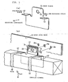
- Fig. 1(a) is a perspective view of a mounting component for a curtain airbag according to an embodiment
- Fig. 1(b) is an exploded perspective view illustrating a mounting structure attached to a vehicle body
- a curtain airbag 1 of an automobile for restraining heads of occupants is mounted on a roof side rail 2 of a vehicle body of the automobile.
- This curtain airbag 1 is formed of two layered sheets connected to each other at the peripheries thereof using sewing threads, bonding agents, or the like so as to form a pouched shape.
- Tabs 3 protrude upward from the upper end of the curtain airbag 1.
- the tabs 3 each have an opening (an opening 3a shown in Fig. 3(b) ; described below) for fixing the curtain airbag 1 to the roof side rail 2.
- the tabs 3 are attached to the roof side rail 2 via mounting components 10.
- the curtain airbag 1 is folded in a compact manner so as to be disposed along the roof side rail 2.
- the folded curtain airbag 1 is fitted into a tubular cover (not shown) composed of, for example, a non-woven fabric, and is retained inside the cover.
- the cover has a plurality of windows such that the tabs 3 are exposed to the exterior of the cover via the windows.
- the mounting components 10 each include a base piece 11 superposed on the roof side rail 2, and projecting pieces 12 extending from the base piece over the folded curtain airbag 1 at both ends of the base piece 11 in the front-back direction of the vehicle.
- the base piece 11 has at the upper portion thereof a through-hole 13 for a bolt or a screw.
- the base piece 11 has catching pieces 14 protruding from the upper portion of both sides of the base pieces 11 toward the roof side rail 2.
- the catching pieces 14 are of an L shape and the ends thereof are bent downward.
- the lower portion of the base piece 11 extends in the front-back direction of the vehicle, and the projecting pieces 12 protrude from the upper sides of the extended portions toward the vehicle cabin so as to be away from the roof side rail 2.
- the base piece 11, the projecting pieces 12, and the catching pieces 14 are formed by bending a flat plate.
- the length of the projecting pieces 12 is smaller than or substantially equal to the width of the folded curtain airbag 1 so as to control the movement of the folded curtain airbag 1 that is made to spring upward as described below.
- the folded curtain airbag 1 is disposed in front of the base pieces 11 and under the projecting pieces 12 of the mounting components 10. At this time, the tabs 3 of the curtain airbag 1 are superposed on the base pieces 11.
- Pieces of tape 15 are wound around the mounting components 10 and the folded curtain airbag so as to surround the mounting components 10 and the folded curtain airbag, thereby integrating the mounting components 10 and the folded curtain airbag 1.
- the pieces of tape 15 are wound around the outer periphery of the projecting pieces 12.
- the width of the pieces of tape 15 is, for example, about 10 mm, and the width of the projecting pieces 12 is set to be larger than or equal to the width of the pieces of tape 15.
- the pieces of tape 15 are ruptured during the expansion of the curtain airbag 1.
- a retaining piece 20 is superposed on each of the tabs 3 such that tabs 3 are held between the retaining pieces 20 and the base pieces 11.
- Each of the retaining pieces 20 has a short cylindrical portion 21 that is fitted into the through-hole 13 of the corresponding base piece 11 via the opening of the corresponding tab 3.
- the cylindrical portions 21 are fixed to the edges of the through-holes 13 by riveting.
- the base pieces 11, the tabs 3, and the retaining pieces 20 may be fixed by means of bonding or the like instead of the above-described riveting.
- the retaining pieces 20 can be omitted, and only the base pieces 11 and the tabs 3 may be used.
- the roof side rail 2 has holes 2a that face the through-holes 13 and slots 2b that face the catching pieces 14.
- the folded curtain airbag 1 having the mounting components 10 integrated therewith as described above is disposed along the roof side rail 2, and the catching pieces 14 are inserted into and hooked on the slots 2b.
- each of the through-holes 13 and the corresponding cylindrical portion 21 become coaxial with the corresponding hole 2a.
- bolts or screws (not shown) are screwed into the holes 2a via the cylindrical portions 21 such that the curtain airbag 1 is mounted on the roof side rail 2.
- the mounting components 10 are not necessarily attached to the B-pillar garnish, but may be attached at any positions in the above-described manner.
- An inflator (not shown) may be connected to an end of the curtain airbag 1, or at a predetermined position in the longitudinal direction of the curtain airbag 1.
- the folded curtain airbag 1 When the folded curtain airbag 1 is made to spring upward in a direction of an arrow R shown in Fig. 1(b) as a result of striking a vehicle member such as the B-pillar garnish during mounting, the movement of the folded curtain airbag 1 is blocked by the projecting pieces 12 extending over the folded curtain airbag 1 and the pieces of tape 15. Therefore, the mounting components 10 are not hidden behind the folded curtain airbag 1, and can be efficiently attached to the roof side rail 2.
- the upward movement of the folded curtain airbag 1 can be regulated more effectively by the projecting pieces 12 disposed at both ends of the corresponding through-holes 13 as described above.
- the mounting components 10 can be temporarily fixed to the roof side rail 2 by the catching pieces 14, and thus the attachment using bolts or screws is facilitated. Moreover, corotation of the mounting components 10 during screwing of the bolts or screws can be prevented by the engagement of the catching pieces 14 with the slots 2b.
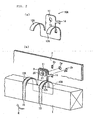
- Fig. 2(a) is a perspective view of a mounting component according to another embodiment
- Fig. 2(b) is an exploded perspective view illustrating a mounting structure for a curtain airbag using this mounting component.
- Mounting components 10A have the same structure as the mounting components 10 except that projecting pieces 12A are of appropriately semicylindrical shapes curving downward.
- the curved portions of the projecting pieces 12A having a radius of curvature of, for example, 13 to 15 mm, cover a folded curtain airbag 1 in the width direction thereof.
- the folded curtain airbag 1 is of an appropriately cylindrical shape since the folded curtain airbag 1 is fitted into a tubular cover as described above. Accordingly, the projecting pieces 12A are preferably disposed so as to fit to the upper portion of the approximately cylindrical folded curtain airbag.
- These mounting components 10A are integrated with the folded curtain airbag 1 as in the above-described embodiment.
- the end of the projecting pieces 12A extend from the upper surface of the folded curtain airbag to the upper portion of the folded curtain airbag adjacent to the vehicle cabin, and thus can block the movement of the folded curtain airbag in the direction of the arrow R to a greater extent.
- Pieces of tape 15 are wound around these projecting pieces 12A. Since the projecting pieces 12A have no angular portions, the durability of the pieces of tape 15 can be enhanced.
- FIGs. 2(a) and 2(b) are the same as in those shown in Figs. 1(a) and 1(b) , and the same reference numerals correspond to the same components.
- Fig. 3(a) is a perspective view of a mounting component for a curtain airbag according to yet another embodiment
- Fig. 3(b) is a perspective view illustrating a folded curtain airbag having the mounting component attached thereto.
- Mounting components 30 each include a base piece 31 superposed on a surface of a roof side rail 2 (not shown in Figs. 3(a) and 3(b) ) adjacent to the vehicle cabin, and projecting pieces 32 connected to the base piece 31 and disposed at both ends of the base piece 31 in the front-back direction of the vehicle.
- the projecting pieces 32 are formed of a U-shaped plate curved downward.
- the base piece 31 is flat, and has a through-hole 33 for a bolt or a screw.
- the base piece 31 extends upward from the projecting pieces 32.
- Each of the mounting components 30 is formed of a flat plate.
- the pair of projecting pieces 32 are formed by bending the flat plate, and the base piece 31 is formed by uprighting a cut portion of the plate.
- the mounting component 30 has an opening 34 created when the base piece 31 is formed.
- the opening 34 is located at the center of the mounting component 30 in the longitudinal direction.
- the length L of the projecting pieces 32 in the front-back direction of the vehicle is preferably 10 to 200 mm, and in particular, approximately 30 to 200 mm.
- a folded curtain airbag 1 is accommodated inside the projecting pieces 32 and tabs 3 are superposed on the base pieces 31.
- the tabs 3 each have an opening 3a.
- the openings 3a are located so as to be coaxial with the through-holes 33 of the base pieces 31.
- the folded curtain airbag protrudes downward from the projecting pieces 32.
- Pieces of tape 15 are wound around the projecting pieces 32 so as to integrate the folded curtain airbag and the mounting components 30.
- the curtain airbag 1 is mounted on the roof side rail 2 by screwing bolts or screws in holes 2a (not shown in Figs. 3(a) and 3(b) ) of the roof side rail 2 via the openings 3a and the through-holes 33 from the side of the tabs 3.
- the folded curtain airbag 1 When the folded curtain airbag 1 is made to move in a direction of an arrow R as a result of striking a B-pillar garnish or the like during mounting, the movement of the folded curtain airbag 1 is blocked by the projecting pieces 32 extending over the upper surface of the folded curtain airbag 1. In particular, even when the folded curtain airbag is pressed upward at a position remote from the base pieces 31, the movement of the folded curtain airbag in the direction of the arrow R in the vicinity of the base piece 31 can be blocked since the length of the projecting pieces 32 in the front-back direction of the vehicle is large.
- the projecting pieces 32 extend from the upper surface of the folded curtain airbag 1 to the surface adjacent to the vehicle cabin such that the movement of the folded curtain airbag 1 in the direction of the arrow R can be blocked sufficiently.
- the pieces of tape 15 have high durability since the projecting pieces 32 are curved.
- the above-described embodiments are merely examples for carrying out the present invention, and embodiments other than those shown in the drawings are permissible in relation to the shapes of the vehicle body at mounting positions.
- the fixing means is not limited to bolts or screws, but may be other means such as clips.
Landscapes
- Engineering & Computer Science (AREA)
- Mechanical Engineering (AREA)
- Air Bags (AREA)
Description
- The present invention relates to mounting components for mounting curtain airbags on, for example, roof side rails of vehicle bodies, and relates to mounting structures for curtain airbags using the mounting components.
- Known technologies for mounting curtain airbags on vehicle bodies using mounting components are disclosed in
JP-A-2002-53003 JP-A-2002-53005 - In these known technologies, folded curtain airbags are disposed along bottom portions of inverted T-shaped (chevron-shaped) mounting components and bound to the mounting components with pieces of tape. The mounting components are attached to roof side rails using bolts.
- According to the mounting components and structures disclosed in
JP-A-2002-53003 JP-A-2002-53005 -
US 2005/046154 A1 relates to a mounting bracket that may be used to attach an inflatable curtain airbag having a manifold to an interior vehicle surface. The side curtain airbag is attached to an inflator that provides in-flation gas to the airbag during an accident. The curtain airbag is secured to the vehicle to ensure that the curtain airbag main-tains a preferred position and orientation during deployment as well as during the normal operation of the vehicle. Thus, one or more mounting brackets are added to mount the curtain airbag to the vehicle. The mounting brackets generally comprise two sections or components, namely a base bracket and a retaining clip. The retaining clip is attachable to the base bracket which, in turn, contacts and/or is affixed to the vehicle interior. The mounting bracket is constructed such that when the retaining clip is attached to the base bracket, the manifold is held between the retaining clip and the base bracket. - An object of the present invention is to provide a mounting component for a curtain airbag capable of preventing a folded curtain airbag from hiding the mounting component even when the folded curtain airbag strikes a B-pillar garnish or the like and thus facilitating efficient mounting of the folded curtain airbag, and to provide a mounting structure for a curtain airbag using this mounting component. This object is achieved with the features of the claims.
- According to the mounting components and structures of the present invention, the upward movement of the folded curtain airbag caused by the folded curtain airbag striking a vehicle member such as a B-pillar garnish can be blocked by the projecting pieces. Therefore, the mounting component is not hidden behind the folded curtain airbag, and the mounting component can be easily attached to the vehicle body.
- Since the projecting pieces are disposed at both ends of the base piece, the folded curtain airbag is sufficiently prevented from hiding the mounting component even when the folded curtain airbag is pushed upward at a position remote from the base piece.
- When each of the projecting pieces has the hanging portion at the end thereof as claimed in
Claim 2, the folded curtain airbag is blocked from rotating upward from a position adjacent to the vehicle cabin. - When the projecting pieces are concaved downward as claimed in
Claim 3 and the pieces of tape are wound so as to surround the outer peripheries of the projecting pieces as claimed in Claim 8, the movement of the folded curtain airbag can be sufficiently blocked. Also, the pieces of tape are not in contact with angular portions, resulting in improved durability. - When the length of the projecting pieces in the front-back direction of the vehicle body is large as claimed in Claim 4, the movement of the folded curtain airbag can be blocked more effectively. When the catching piece is engaged with the catching hole of the vehicle body as claimed in Claim 5, the rotation of the mounting component can be blocked more effectively.
- When the tab is interposed between the retaining piece and the base piece as claimed in Claim 7, the tab is prevented from warping during mounting of the curtain airbag. Thus, the mounting work efficiency is improved.
- Embodiments will now be described with reference to the drawings.
-
Fig. 1(a) is a perspective view of a mounting component for a curtain airbag according to an embodiment, andFig. 1(b) is an exploded perspective view illustrating a mounting structure attached to a vehicle body; -
Fig. 2(a) is a perspective view of a mounting component according to another embodiment, andFig. 2(b) is an exploded perspective view illustrating a mounting structure for a curtain airbag using this mounting component; -
Fig. 3(a) is a perspective view of a mounting component for a curtain airbag according to yet another embodiment, andFig. 3(b) is a perspective view illustrating a folded curtain airbag having the mounting component attached thereto; and -
Fig. 4 is a perspective view of the folded curtain airbag with the mounting component. - In the embodiment of
Figs. 1(a) and 1(b) , acurtain airbag 1 of an automobile for restraining heads of occupants is mounted on aroof side rail 2 of a vehicle body of the automobile. Thiscurtain airbag 1 is formed of two layered sheets connected to each other at the peripheries thereof using sewing threads, bonding agents, or the like so as to form a pouched shape.Tabs 3 protrude upward from the upper end of thecurtain airbag 1. Thetabs 3 each have an opening (an opening 3a shown inFig. 3(b) ; described below) for fixing thecurtain airbag 1 to theroof side rail 2. Thetabs 3 are attached to theroof side rail 2 viamounting components 10. - At this time, the
curtain airbag 1 is folded in a compact manner so as to be disposed along theroof side rail 2. The foldedcurtain airbag 1 is fitted into a tubular cover (not shown) composed of, for example, a non-woven fabric, and is retained inside the cover. The cover has a plurality of windows such that thetabs 3 are exposed to the exterior of the cover via the windows. - The
mounting components 10 each include abase piece 11 superposed on theroof side rail 2, and projectingpieces 12 extending from the base piece over the foldedcurtain airbag 1 at both ends of thebase piece 11 in the front-back direction of the vehicle. In this embodiment, thebase piece 11 has at the upper portion thereof a through-hole 13 for a bolt or a screw. Moreover, thebase piece 11 has catchingpieces 14 protruding from the upper portion of both sides of thebase pieces 11 toward theroof side rail 2. Thecatching pieces 14 are of an L shape and the ends thereof are bent downward. - The lower portion of the
base piece 11 extends in the front-back direction of the vehicle, and the projectingpieces 12 protrude from the upper sides of the extended portions toward the vehicle cabin so as to be away from theroof side rail 2. In this embodiment, thebase piece 11, theprojecting pieces 12, and thecatching pieces 14 are formed by bending a flat plate. The length of the projectingpieces 12 is smaller than or substantially equal to the width of the foldedcurtain airbag 1 so as to control the movement of the foldedcurtain airbag 1 that is made to spring upward as described below. - The folded
curtain airbag 1 is disposed in front of thebase pieces 11 and under the projectingpieces 12 of themounting components 10. At this time, thetabs 3 of thecurtain airbag 1 are superposed on thebase pieces 11. - Pieces of
tape 15 are wound around themounting components 10 and the folded curtain airbag so as to surround themounting components 10 and the folded curtain airbag, thereby integrating themounting components 10 and the foldedcurtain airbag 1. The pieces oftape 15 are wound around the outer periphery of the projectingpieces 12. The width of the pieces oftape 15 is, for example, about 10 mm, and the width of the projectingpieces 12 is set to be larger than or equal to the width of the pieces oftape 15. The pieces oftape 15 are ruptured during the expansion of thecurtain airbag 1. - In this embodiment, a
retaining piece 20 is superposed on each of thetabs 3 such thattabs 3 are held between theretaining pieces 20 and thebase pieces 11. Each of theretaining pieces 20 has a shortcylindrical portion 21 that is fitted into the through-hole 13 of thecorresponding base piece 11 via the opening of thecorresponding tab 3. Thecylindrical portions 21 are fixed to the edges of the through-holes 13 by riveting. Thebase pieces 11, thetabs 3, and theretaining pieces 20 may be fixed by means of bonding or the like instead of the above-described riveting. Theretaining pieces 20 can be omitted, and only thebase pieces 11 and thetabs 3 may be used. - The
roof side rail 2 hasholes 2a that face the through-holes 13 andslots 2b that face thecatching pieces 14. - The folded
curtain airbag 1 having themounting components 10 integrated therewith as described above is disposed along theroof side rail 2, and the catchingpieces 14 are inserted into and hooked on theslots 2b. Thus, each of the through-holes 13 and the correspondingcylindrical portion 21 become coaxial with thecorresponding hole 2a. Then, bolts or screws (not shown) are screwed into theholes 2a via thecylindrical portions 21 such that thecurtain airbag 1 is mounted on theroof side rail 2. As shown inFig. 4 , themounting components 10 are not necessarily attached to the B-pillar garnish, but may be attached at any positions in the above-described manner. A curtain airbag 1' shown inFig. 4 is inflated, and has expanded portions 1'e, non-expanded portions 1'f, and a non-expanded portion 1'g provided by means of seams. An inflator (not shown) may be connected to an end of thecurtain airbag 1, or at a predetermined position in the longitudinal direction of thecurtain airbag 1. - When the folded
curtain airbag 1 is made to spring upward in a direction of an arrow R shown inFig. 1(b) as a result of striking a vehicle member such as the B-pillar garnish during mounting, the movement of the foldedcurtain airbag 1 is blocked by the projectingpieces 12 extending over the foldedcurtain airbag 1 and the pieces oftape 15. Therefore, themounting components 10 are not hidden behind the foldedcurtain airbag 1, and can be efficiently attached to theroof side rail 2. In particular, the upward movement of the foldedcurtain airbag 1 can be regulated more effectively by the projectingpieces 12 disposed at both ends of the corresponding through-holes 13 as described above. - In this embodiment, the mounting
components 10 can be temporarily fixed to theroof side rail 2 by the catchingpieces 14, and thus the attachment using bolts or screws is facilitated. Moreover, corotation of the mountingcomponents 10 during screwing of the bolts or screws can be prevented by the engagement of the catchingpieces 14 with theslots 2b. -
Fig. 2(a) is a perspective view of a mounting component according to another embodiment, andFig. 2(b) is an exploded perspective view illustrating a mounting structure for a curtain airbag using this mounting component. - Mounting
components 10A have the same structure as the mountingcomponents 10 except that projectingpieces 12A are of appropriately semicylindrical shapes curving downward. The curved portions of the projectingpieces 12A having a radius of curvature of, for example, 13 to 15 mm, cover a foldedcurtain airbag 1 in the width direction thereof. The foldedcurtain airbag 1 is of an appropriately cylindrical shape since the foldedcurtain airbag 1 is fitted into a tubular cover as described above. Accordingly, the projectingpieces 12A are preferably disposed so as to fit to the upper portion of the approximately cylindrical folded curtain airbag. - These mounting
components 10A are integrated with the foldedcurtain airbag 1 as in the above-described embodiment. - In this embodiment, the end of the projecting
pieces 12A extend from the upper surface of the folded curtain airbag to the upper portion of the folded curtain airbag adjacent to the vehicle cabin, and thus can block the movement of the folded curtain airbag in the direction of the arrow R to a greater extent. Pieces oftape 15 are wound around these projectingpieces 12A. Since the projectingpieces 12A have no angular portions, the durability of the pieces oftape 15 can be enhanced. - Other structures shown in
Figs. 2(a) and 2(b) are the same as in those shown inFigs. 1(a) and 1(b) , and the same reference numerals correspond to the same components. -
Fig. 3(a) is a perspective view of a mounting component for a curtain airbag according to yet another embodiment, andFig. 3(b) is a perspective view illustrating a folded curtain airbag having the mounting component attached thereto. - Mounting
components 30 according to this embodiment each include abase piece 31 superposed on a surface of a roof side rail 2 (not shown inFigs. 3(a) and 3(b) ) adjacent to the vehicle cabin, and projectingpieces 32 connected to thebase piece 31 and disposed at both ends of thebase piece 31 in the front-back direction of the vehicle. The projectingpieces 32 are formed of a U-shaped plate curved downward. Thebase piece 31 is flat, and has a through-hole 33 for a bolt or a screw. Thebase piece 31 extends upward from the projectingpieces 32. - Each of the mounting
components 30 is formed of a flat plate. The pair of projectingpieces 32 are formed by bending the flat plate, and thebase piece 31 is formed by uprighting a cut portion of the plate. The mountingcomponent 30 has anopening 34 created when thebase piece 31 is formed. Theopening 34 is located at the center of the mountingcomponent 30 in the longitudinal direction.
The length L of the projectingpieces 32 in the front-back direction of the vehicle (the length from the edge of theopening 34 to the end of the mountingcomponent 30 in the longitudinal direction) is preferably 10 to 200 mm, and in particular, approximately 30 to 200 mm. - A folded
curtain airbag 1 is accommodated inside the projectingpieces 32 andtabs 3 are superposed on thebase pieces 31. Thetabs 3 each have anopening 3a. Theopenings 3a are located so as to be coaxial with the through-holes 33 of thebase pieces 31. - The folded curtain airbag protrudes downward from the projecting
pieces 32. Pieces oftape 15 are wound around the projectingpieces 32 so as to integrate the folded curtain airbag and the mountingcomponents 30. - The
curtain airbag 1 is mounted on theroof side rail 2 by screwing bolts or screws inholes 2a (not shown inFigs. 3(a) and 3(b) ) of theroof side rail 2 via theopenings 3a and the through-holes 33 from the side of thetabs 3. - When the folded
curtain airbag 1 is made to move in a direction of an arrow R as a result of striking a B-pillar garnish or the like during mounting, the movement of the foldedcurtain airbag 1 is blocked by the projectingpieces 32 extending over the upper surface of the foldedcurtain airbag 1. In particular, even when the folded curtain airbag is pressed upward at a position remote from thebase pieces 31, the movement of the folded curtain airbag in the direction of the arrow R in the vicinity of thebase piece 31 can be blocked since the length of the projectingpieces 32 in the front-back direction of the vehicle is large. - Also in this embodiment, the projecting
pieces 32 extend from the upper surface of the foldedcurtain airbag 1 to the surface adjacent to the vehicle cabin such that the movement of the foldedcurtain airbag 1 in the direction of the arrow R can be blocked sufficiently. Moreover, the pieces oftape 15 have high durability since the projectingpieces 32 are curved. - The above-described embodiments are merely examples for carrying out the present invention, and embodiments other than those shown in the drawings are permissible in relation to the shapes of the vehicle body at mounting positions. The fixing means is not limited to bolts or screws, but may be other means such as clips.
Claims (11)
- A mounting component for mounting a folded curtain airbag (1) that is made from a flat plate and that extends along a vehicle body on the vehicle body, comprising:(a) projecting pieces (12; 12A; 32) extending from both ends of a base piece (11; 31) over the folded curtain airbag (1), wherein(b) the projecting pieces (12; 12A; 32) are bent from the flat plate downwardly and are adapted to accommodate the folded curtain airbag (1) inside the projecting pieces (32), and(c) the base piece (11; 31) is an upright portion which is a cut portion of the plate creating an opening (34) at the center of the mounting component (10; 30),(d) the base piece (11; 31) and the projecting pieces (12; 12A; 32) are integrated with each other, and(e) the base piece (11; 31) is adapted to attach the mounting component (10; 30) and the curtain airbag (1) to the vehicle body.
- The mounting component according to Claim 1, wherein each of the projecting pieces (12, 12A) comprises a hanging portion at the end thereof extending over a surface of the folded curtain airbag adjacent to a vehicle cabin.
- The mounting component according to Claim 2, wherein the longitudinal section of the projecting pieces (12A) is concaved in a downward direction.
- The mounting component according to any one of Claims 1 to 3, wherein the width of the projecting pieces (12, 12A) is 10 mm or more.
- The mounting component according to any one of Claims 1 to 4, further comprising:a catching piece (14) engaged with a catching hole (2b) formed in the vehicle body.
- A mounting structure having a folded curtain airbag that is mounted on a vehicle body using a mounting component according to any one of Claims 1 to 5; wherein
the curtain airbag (1) comprises a tab (3) protruding therefrom and superposed on the base piece (11) of the mounting component (10, 10A, 30); and
the tab (3) is attached to the vehicle body via the base piece (11). - The mounting structure according to Claim 6, wherein
the tab (3) is superposed on a surface of the base piece (11) adjacent.to the vehicle cabin, and a retaining piece (20) is superposed on a surface of the tab (3) adjacent to the vehicle cabin; and
the retaining piece (20) and the base piece (11) are integrated with each other. - The mounting structure according Claim 6 or 7, wherein
the folded curtain airbag (1) and the mounting component (10, 10A, 30) are integrated with each other by tape members (15) wound around the folded curtain airbag (1) and the mounting component (10, 10A, 30); and
the tape members (15) surround the outer peripheries of the projecting pieces (12, 12A). - A curtain airbag module to be for mounted on a vehicle body, said curtain airbag module comprising:a folded curtain airbag;a mounting component according to any one of Claims 1 to 5; anda tab (3) protruding from the curtain airbag (1) and being superposed on the base piece (11) of the mounting component (10, 10A, 30); whereinthe tab (3) is adapted for attachment to the vehicle body via the base piece (11).
- The curtain airbag module according to Claim 9,
wherein
the tab (3) is superposed on a surface of the base piece (11) adjacent to the vehicle cabin, and a retaining piece (20) is superposed on a surface of the tab (3) adjacent to the vehicle cabin; and
the retaining piece (20) and the base piece (11) are integrated with each other. - The curtain airbag module according Claim 9 or 10, wherein
the folded curtain airbag (1) and the mounting component (10, 10A, 30) are integrated with each other by tape members (15) wound around the folded curtain airbag (1) and the mounting component (10, 10A, 30); and
the tape members (15) surround the outer peripheries of the projecting pieces (12, 12A).
Applications Claiming Priority (1)
| Application Number | Priority Date | Filing Date | Title |
|---|---|---|---|
| JP2005272607A JP4736665B2 (en) | 2005-09-20 | 2005-09-20 | Curtain airbag mounting bracket and mounting structure, and curtain airbag device |
Publications (3)
| Publication Number | Publication Date |
|---|---|
| EP1764271A2 EP1764271A2 (en) | 2007-03-21 |
| EP1764271A3 EP1764271A3 (en) | 2008-05-28 |
| EP1764271B1 true EP1764271B1 (en) | 2010-08-25 |
Family
ID=37526957
Family Applications (1)
| Application Number | Title | Priority Date | Filing Date |
|---|---|---|---|
| EP06018970A Not-in-force EP1764271B1 (en) | 2005-09-20 | 2006-09-11 | Mounting component and mounting structure for curtain airbag |
Country Status (5)
| Country | Link |
|---|---|
| US (1) | US7780187B2 (en) |
| EP (1) | EP1764271B1 (en) |
| JP (1) | JP4736665B2 (en) |
| CN (1) | CN1935562B (en) |
| DE (1) | DE602006016384D1 (en) |
Families Citing this family (45)
| Publication number | Priority date | Publication date | Assignee | Title |
|---|---|---|---|---|
| US7731224B2 (en) * | 2006-03-01 | 2010-06-08 | Trw Vehicle Safety Systems Inc. | Inflatable curtain |
| US7523958B2 (en) * | 2006-03-14 | 2009-04-28 | Delphi Technologies, Inc. | Bracket for securing side airbag for automotive vehicle |
| EP2363327B1 (en) * | 2006-04-04 | 2012-12-05 | Autoliv Development AB | Guide plate for side air bag |
| JP2008247113A (en) * | 2007-03-29 | 2008-10-16 | Toyoda Gosei Co Ltd | Air bag device |
| JP4710862B2 (en) * | 2007-04-02 | 2011-06-29 | 豊田合成株式会社 | Air bag device for knee protection |
| JP5128229B2 (en) | 2007-10-04 | 2013-01-23 | 本田技研工業株式会社 | Bracket for vehicle |
| JP5001780B2 (en) * | 2007-10-09 | 2012-08-15 | 本田技研工業株式会社 | Airbag device for vehicle |
| JP5154297B2 (en) | 2008-05-08 | 2013-02-27 | タカタ株式会社 | Curtain airbag bracket and curtain airbag device |
| JP2009262673A (en) * | 2008-04-23 | 2009-11-12 | Takata Corp | Bracket for curtain airbag and curtain airbag device |
| JP2009292441A (en) | 2008-06-09 | 2009-12-17 | Takata Corp | Curtain airbag bracket and curtain airbag apparatus |
| DE102008026631B4 (en) * | 2008-06-04 | 2011-02-10 | Benteler Automobiltechnik Gmbh | Instrument carrier and method for its production |
| US7815252B2 (en) * | 2008-12-04 | 2010-10-19 | Ford Global Technologies, Llc | Anti-rotation clip for moon roof drain tube |
| DE102008061282B4 (en) * | 2008-12-11 | 2021-03-04 | Autoliv Development Ab | Curtain airbag for a motor vehicle and fitting part for fastening a curtain airbag to a motor vehicle |
| JP2012179923A (en) * | 2009-09-25 | 2012-09-20 | Autoliv Development Ab | Curtain airbag device |
| JP5574656B2 (en) * | 2009-09-25 | 2014-08-20 | オートリブ ディベロップメント エービー | Curtain airbag device |
| KR101113672B1 (en) * | 2009-10-30 | 2012-02-17 | 아우토리브 디벨롭먼트 아베 | Ramp apparatus of curtain air bag for vehicle |
| US8475525B2 (en) * | 2010-01-22 | 2013-07-02 | 4Tech Inc. | Tricuspid valve repair using tension |
| CN102398561B (en) * | 2010-09-13 | 2015-09-09 | 奥托立夫开发公司 | Automotive safety air curtain support |
| EP2666677B1 (en) * | 2011-01-17 | 2017-06-14 | Autoliv Development AB | Cover and air bag device |
| JP5626121B2 (en) * | 2011-05-26 | 2014-11-19 | 豊田合成株式会社 | Head protection airbag device |
| US8474866B1 (en) * | 2012-03-08 | 2013-07-02 | Toyota Motor Engineering & Manufacturing North America, Inc. | Airbag with zones of less elastic material |
| JP5783141B2 (en) * | 2012-07-04 | 2015-09-24 | トヨタ車体株式会社 | Temporary claw for automotive interior parts |
| KR20140012284A (en) * | 2012-07-19 | 2014-02-03 | 아우토리브 디벨롭먼트 아베 | Mounting apparatus for curtatin airbag |
| EP3165410B1 (en) | 2012-10-19 | 2018-04-18 | Autoliv Development AB | Curtain airbag device |
| KR101605814B1 (en) * | 2013-06-19 | 2016-03-25 | 아우토리브 디벨롭먼트 아베 | Mounting bracket of curtain airbag for vehicle |
| JP5714746B2 (en) * | 2014-04-30 | 2015-05-07 | オートリブ ディベロップメント エービー | Curtain airbag device |
| JP6465352B2 (en) * | 2015-04-23 | 2019-02-06 | 本田技研工業株式会社 | Side curtain airbag fixing structure |
| JP2018520936A (en) * | 2015-07-07 | 2018-08-02 | トヨタ ボウショク アメリカ インコーポレーテッド | Misinstallation prevention bracket for installing airbag strip for seat trim cover on seat frame |
| JP6158870B2 (en) | 2015-08-05 | 2017-07-05 | 本田技研工業株式会社 | Airbag device |
| US9616840B2 (en) * | 2015-08-14 | 2017-04-11 | Toyota Motor Engineering & Manufacturing North America, Inc. | Inspection windows for curtain side airbag systems |
| US9896054B2 (en) * | 2016-01-28 | 2018-02-20 | Toyota Motor Engineering & Manufacturing North America, Inc. | Dual purpose temporary clip for vehicle |
| CN107310521A (en) * | 2016-04-26 | 2017-11-03 | 福特环球技术公司 | Connector and restraint assembly for vehicle |
| JP6597504B2 (en) * | 2016-07-13 | 2019-10-30 | 豊田合成株式会社 | Head protection airbag device |
| DE102016120177A1 (en) * | 2016-10-24 | 2018-04-26 | Trw Automotive Gmbh | Airbag module |
| US10787144B1 (en) * | 2017-08-23 | 2020-09-29 | Fenton Mobility Products, Inc. | Headliner bar assembly for compliant airbags |
| JP6954235B2 (en) * | 2018-06-25 | 2021-10-27 | 豊田合成株式会社 | Head protection airbag device |
| US10829074B2 (en) | 2018-08-27 | 2020-11-10 | Autoliv Asp, Inc. | Knee airbag assemblies |
| US20200086819A1 (en) * | 2018-09-18 | 2020-03-19 | GM Global Technology Operations LLC | Fastener for a roof rail air bag in a vehicle and a roof rail airbag assembly including the fastener |
| DE202018106999U1 (en) * | 2018-12-07 | 2020-03-10 | Dalphi Metal Espana, S.A. | Fastening element for mounting an airbag module on the vehicle |
| CN109606304A (en) * | 2018-12-26 | 2019-04-12 | 北京长城华冠汽车技术开发有限公司 | Gas curtain fixed structure and automobile safety air curtain |
| JP6860603B2 (en) * | 2019-03-01 | 2021-04-14 | 本田技研工業株式会社 | Temporary fixing structure of airbag device |
| CN112172732B (en) * | 2019-07-01 | 2023-07-14 | 奥托立夫开发公司 | Airbag module |
| US11377059B2 (en) | 2020-03-23 | 2022-07-05 | Autoliv Asp, Inc. | Subtotal enclosures for airbag assemblies |
| US11999312B2 (en) * | 2021-01-20 | 2024-06-04 | Autoliv Asp, Inc. | Integrated fastener/stiffener pieces for airbag mounting |
| KR20220150509A (en) * | 2021-05-04 | 2022-11-11 | 현대모비스 주식회사 | Apparatus for mounting curtain air bag cushion |
Family Cites Families (25)
| Publication number | Priority date | Publication date | Assignee | Title |
|---|---|---|---|---|
| JPH10217905A (en) * | 1997-01-31 | 1998-08-18 | Suzuki Motor Corp | Mounting structure of seat belt adjuster |
| JP2920291B2 (en) * | 1997-08-28 | 1999-07-19 | トヨタ自動車株式会社 | Head protection airbag device |
| DE29806080U1 (en) * | 1998-04-02 | 1998-08-06 | TRW Occupant Restraint Systems GmbH & Co. KG, 73553 Alfdorf | Handle console |
| JP3093199B2 (en) * | 1998-05-12 | 2000-10-03 | トヨタ自動車株式会社 | Arrangement structure of head protection airbag device |
| JP3536666B2 (en) * | 1998-05-12 | 2004-06-14 | 豊田合成株式会社 | Side airbag device |
| JP3113977B2 (en) * | 1998-05-12 | 2000-12-04 | 豊田合成株式会社 | Side airbag device airbag |
| JP3474109B2 (en) | 1998-07-16 | 2003-12-08 | トヨタ自動車株式会社 | Head protection airbag bag fixing structure |
| JP3750364B2 (en) * | 1998-09-04 | 2006-03-01 | タカタ株式会社 | Crew protection curtain, its mounting structure and mounting method |
| JP3160670B2 (en) * | 1999-02-26 | 2001-04-25 | 豊田合成株式会社 | Head protection airbag device |
| EP2186689B1 (en) * | 1999-12-27 | 2016-11-30 | Toyoda Gosei Co., Ltd. | Head protecting air bag apparatus |
| US6540251B1 (en) * | 2000-03-31 | 2003-04-01 | Illinois Tool Works Inc. | Side airbag retention system and fastener |
| JP3590333B2 (en) * | 2000-08-08 | 2004-11-17 | トヨタ自動車株式会社 | Arrangement structure of head protection airbag device |
| JP3487272B2 (en) * | 2000-08-08 | 2004-01-13 | トヨタ自動車株式会社 | Head protection airbag device |
| GB2367537B (en) * | 2000-10-03 | 2003-12-03 | Autoliv Dev | Improvements in or relating to an arrangement for mounting an inflatable element |
| US6705635B2 (en) * | 2001-08-01 | 2004-03-16 | Autoliv Asp, Inc. | Apparatus and method for rapidly fastening an airbag apparatus |
| US6851702B2 (en) * | 2001-08-29 | 2005-02-08 | Autoliv Asp, Inc. | Mounting assembly for inflatable curtain |
| JP3904896B2 (en) * | 2001-11-09 | 2007-04-11 | 豊田合成株式会社 | Head protection airbag device |
| JP4045884B2 (en) * | 2002-07-22 | 2008-02-13 | タカタ株式会社 | Curtain airbag guide member and curtain airbag device |
| JP3961406B2 (en) * | 2002-11-19 | 2007-08-22 | ポップリベット・ファスナー株式会社 | Curtain airbag fixing tool |
| JP4019927B2 (en) * | 2002-12-20 | 2007-12-12 | 豊田合成株式会社 | Head protection airbag device |
| JP4355161B2 (en) * | 2003-04-16 | 2009-10-28 | 株式会社寺岡製作所 | Adhesive tape for binding airbags |
| US20050046154A1 (en) * | 2003-09-03 | 2005-03-03 | Rhea Scott L. | Inflatable curtain mounting bracket |
| JP2005178605A (en) * | 2003-12-19 | 2005-07-07 | Takata Corp | Curtain air bag device |
| US7175196B2 (en) * | 2004-02-09 | 2007-02-13 | Trw Vehicle Safety Systems Inc. | Support bracket for an inflatable curtain |
| US7357408B2 (en) * | 2005-02-28 | 2008-04-15 | Autoliv Asp, Inc. | Inflatable curtain cushion tab shock absorption |
-
2005
- 2005-09-20 JP JP2005272607A patent/JP4736665B2/en not_active Expired - Fee Related
-
2006
- 2006-09-11 DE DE602006016384T patent/DE602006016384D1/en active Active
- 2006-09-11 EP EP06018970A patent/EP1764271B1/en not_active Not-in-force
- 2006-09-18 US US11/522,443 patent/US7780187B2/en not_active Expired - Fee Related
- 2006-09-20 CN CN2006101389525A patent/CN1935562B/en not_active Expired - Fee Related
Also Published As
| Publication number | Publication date |
|---|---|
| EP1764271A3 (en) | 2008-05-28 |
| CN1935562A (en) | 2007-03-28 |
| JP2007083781A (en) | 2007-04-05 |
| JP4736665B2 (en) | 2011-07-27 |
| CN1935562B (en) | 2011-04-06 |
| EP1764271A2 (en) | 2007-03-21 |
| US7780187B2 (en) | 2010-08-24 |
| US20070063490A1 (en) | 2007-03-22 |
| DE602006016384D1 (en) | 2010-10-07 |
Similar Documents
| Publication | Publication Date | Title |
|---|---|---|
| EP1764271A2 (en) | Mounting component and mounting structure for curtain airbag | |
| JP3777552B2 (en) | Pillar trim installation structure for vehicles with curtain airbags | |
| EP1948483B1 (en) | Flexible housing for an airbag module | |
| US6991256B2 (en) | Quick connect cushion mounting system | |
| CN101466574B (en) | Pillar garnish mounting structure for a head-protecting air bag apparatus | |
| JP4093140B2 (en) | Head protection airbag device | |
| US7025377B2 (en) | Curtain air bag device | |
| JP2002362292A (en) | Occupant restraint | |
| EP1842741A2 (en) | Guide plate for side air bag | |
| JP4852510B2 (en) | Airbag mounting bracket | |
| EP1644224B1 (en) | Inflatable curtain asssembly | |
| US9555761B2 (en) | Inflatable curtain airbag assembly | |
| JP3741061B2 (en) | Shock absorption structure at the top of the car body | |
| JP2003063351A (en) | Passenger constraint device | |
| JP2009292441A (en) | Curtain airbag bracket and curtain airbag apparatus | |
| US20090152838A1 (en) | Airbag inflator device and method of installation | |
| WO2007005092A2 (en) | Flexible housing for an airbag module | |
| JP4211826B2 (en) | Vehicle interior mounting structure with head protection airbag device | |
| EP1621416B1 (en) | Airbag unit and case of the unit | |
| JP4134882B2 (en) | Curtain airbag device | |
| JP4765620B2 (en) | Vehicle occupant restraint system | |
| KR20240075167A (en) | Fixture for roof airbag of driverless vehicles | |
| JP6450544B2 (en) | Curtain airbag device mounting structure and curtain airbag device | |
| JP2009006887A (en) | Curtain airbag device | |
| JP2007182134A (en) | Curtain airbag device |
Legal Events
| Date | Code | Title | Description |
|---|---|---|---|
| PUAI | Public reference made under article 153(3) epc to a published international application that has entered the european phase |
Free format text: ORIGINAL CODE: 0009012 |
|
| AK | Designated contracting states |
Kind code of ref document: A2 Designated state(s): AT BE BG CH CY CZ DE DK EE ES FI FR GB GR HU IE IS IT LI LT LU LV MC NL PL PT RO SE SI SK TR |
|
| AX | Request for extension of the european patent |
Extension state: AL BA HR MK YU |
|
| PUAL | Search report despatched |
Free format text: ORIGINAL CODE: 0009013 |
|
| AK | Designated contracting states |
Kind code of ref document: A3 Designated state(s): AT BE BG CH CY CZ DE DK EE ES FI FR GB GR HU IE IS IT LI LT LU LV MC NL PL PT RO SE SI SK TR |
|
| AX | Request for extension of the european patent |
Extension state: AL BA HR MK RS |
|
| 17P | Request for examination filed |
Effective date: 20080829 |
|
| 17Q | First examination report despatched |
Effective date: 20081029 |
|
| AKX | Designation fees paid |
Designated state(s): DE FR GB |
|
| GRAP | Despatch of communication of intention to grant a patent |
Free format text: ORIGINAL CODE: EPIDOSNIGR1 |
|
| GRAS | Grant fee paid |
Free format text: ORIGINAL CODE: EPIDOSNIGR3 |
|
| GRAA | (expected) grant |
Free format text: ORIGINAL CODE: 0009210 |
|
| AK | Designated contracting states |
Kind code of ref document: B1 Designated state(s): DE FR GB |
|
| REG | Reference to a national code |
Ref country code: GB Ref legal event code: FG4D |
|
| REF | Corresponds to: |
Ref document number: 602006016384 Country of ref document: DE Date of ref document: 20101007 Kind code of ref document: P |
|
| PLBE | No opposition filed within time limit |
Free format text: ORIGINAL CODE: 0009261 |
|
| STAA | Information on the status of an ep patent application or granted ep patent |
Free format text: STATUS: NO OPPOSITION FILED WITHIN TIME LIMIT |
|
| 26N | No opposition filed |
Effective date: 20110526 |
|
| REG | Reference to a national code |
Ref country code: DE Ref legal event code: R097 Ref document number: 602006016384 Country of ref document: DE Effective date: 20110526 |
|
| PGFP | Annual fee paid to national office [announced via postgrant information from national office to epo] |
Ref country code: FR Payment date: 20130910 Year of fee payment: 8 Ref country code: GB Payment date: 20130911 Year of fee payment: 8 |
|
| GBPC | Gb: european patent ceased through non-payment of renewal fee |
Effective date: 20140911 |
|
| REG | Reference to a national code |
Ref country code: FR Ref legal event code: ST Effective date: 20150529 |
|
| PG25 | Lapsed in a contracting state [announced via postgrant information from national office to epo] |
Ref country code: GB Free format text: LAPSE BECAUSE OF NON-PAYMENT OF DUE FEES Effective date: 20140911 |
|
| PG25 | Lapsed in a contracting state [announced via postgrant information from national office to epo] |
Ref country code: FR Free format text: LAPSE BECAUSE OF NON-PAYMENT OF DUE FEES Effective date: 20140930 |
|
| REG | Reference to a national code |
Ref country code: DE Ref legal event code: R082 Ref document number: 602006016384 Country of ref document: DE Representative=s name: VOSSIUS & PARTNER PATENTANWAELTE RECHTSANWAELT, DE Ref country code: DE Ref legal event code: R081 Ref document number: 602006016384 Country of ref document: DE Owner name: JOYSON SAFETY SYSTEMS JAPAN K.K., JP Free format text: FORMER OWNER: TAKATA CORP., TOKIO/TOKYO, JP |
|
| PGFP | Annual fee paid to national office [announced via postgrant information from national office to epo] |
Ref country code: DE Payment date: 20180920 Year of fee payment: 13 |
|
| REG | Reference to a national code |
Ref country code: DE Ref legal event code: R119 Ref document number: 602006016384 Country of ref document: DE |
|
| PG25 | Lapsed in a contracting state [announced via postgrant information from national office to epo] |
Ref country code: DE Free format text: LAPSE BECAUSE OF NON-PAYMENT OF DUE FEES Effective date: 20200401 |