EP1764052A1 - Bone stabilization system - Google Patents
Bone stabilization system Download PDFInfo
- Publication number
- EP1764052A1 EP1764052A1 EP06254837A EP06254837A EP1764052A1 EP 1764052 A1 EP1764052 A1 EP 1764052A1 EP 06254837 A EP06254837 A EP 06254837A EP 06254837 A EP06254837 A EP 06254837A EP 1764052 A1 EP1764052 A1 EP 1764052A1
- Authority
- EP
- European Patent Office
- Prior art keywords
- screw
- locking
- thread
- type
- plate
- Prior art date
- Legal status (The legal status is an assumption and is not a legal conclusion. Google has not performed a legal analysis and makes no representation as to the accuracy of the status listed.)
- Granted
Links
Images


Classifications
-
- A—HUMAN NECESSITIES
- A61—MEDICAL OR VETERINARY SCIENCE; HYGIENE
- A61B—DIAGNOSIS; SURGERY; IDENTIFICATION
- A61B17/00—Surgical instruments, devices or methods, e.g. tourniquets
- A61B17/56—Surgical instruments or methods for treatment of bones or joints; Devices specially adapted therefor
- A61B17/58—Surgical instruments or methods for treatment of bones or joints; Devices specially adapted therefor for osteosynthesis, e.g. bone plates, screws, setting implements or the like
- A61B17/68—Internal fixation devices, including fasteners and spinal fixators, even if a part thereof projects from the skin
- A61B17/80—Cortical plates, i.e. bone plates; Instruments for holding or positioning cortical plates, or for compressing bones attached to cortical plates
- A61B17/8061—Cortical plates, i.e. bone plates; Instruments for holding or positioning cortical plates, or for compressing bones attached to cortical plates specially adapted for particular bones
-
- A—HUMAN NECESSITIES
- A61—MEDICAL OR VETERINARY SCIENCE; HYGIENE
- A61B—DIAGNOSIS; SURGERY; IDENTIFICATION
- A61B17/00—Surgical instruments, devices or methods, e.g. tourniquets
- A61B17/56—Surgical instruments or methods for treatment of bones or joints; Devices specially adapted therefor
- A61B17/58—Surgical instruments or methods for treatment of bones or joints; Devices specially adapted therefor for osteosynthesis, e.g. bone plates, screws, setting implements or the like
- A61B17/68—Internal fixation devices, including fasteners and spinal fixators, even if a part thereof projects from the skin
- A61B17/80—Cortical plates, i.e. bone plates; Instruments for holding or positioning cortical plates, or for compressing bones attached to cortical plates
- A61B17/8052—Cortical plates, i.e. bone plates; Instruments for holding or positioning cortical plates, or for compressing bones attached to cortical plates immobilised relative to screws by interlocking form of the heads and plate holes, e.g. conical or threaded
- A61B17/8057—Cortical plates, i.e. bone plates; Instruments for holding or positioning cortical plates, or for compressing bones attached to cortical plates immobilised relative to screws by interlocking form of the heads and plate holes, e.g. conical or threaded the interlocking form comprising a thread
-
- A—HUMAN NECESSITIES
- A61—MEDICAL OR VETERINARY SCIENCE; HYGIENE
- A61B—DIAGNOSIS; SURGERY; IDENTIFICATION
- A61B17/00—Surgical instruments, devices or methods, e.g. tourniquets
- A61B17/56—Surgical instruments or methods for treatment of bones or joints; Devices specially adapted therefor
- A61B17/58—Surgical instruments or methods for treatment of bones or joints; Devices specially adapted therefor for osteosynthesis, e.g. bone plates, screws, setting implements or the like
- A61B17/68—Internal fixation devices, including fasteners and spinal fixators, even if a part thereof projects from the skin
- A61B17/84—Fasteners therefor or fasteners being internal fixation devices
- A61B17/86—Pins or screws or threaded wires; nuts therefor
- A61B17/8605—Heads, i.e. proximal ends projecting from bone
-
- A—HUMAN NECESSITIES
- A61—MEDICAL OR VETERINARY SCIENCE; HYGIENE
- A61B—DIAGNOSIS; SURGERY; IDENTIFICATION
- A61B17/00—Surgical instruments, devices or methods, e.g. tourniquets
- A61B17/56—Surgical instruments or methods for treatment of bones or joints; Devices specially adapted therefor
- A61B17/58—Surgical instruments or methods for treatment of bones or joints; Devices specially adapted therefor for osteosynthesis, e.g. bone plates, screws, setting implements or the like
- A61B17/68—Internal fixation devices, including fasteners and spinal fixators, even if a part thereof projects from the skin
- A61B17/84—Fasteners therefor or fasteners being internal fixation devices
- A61B17/86—Pins or screws or threaded wires; nuts therefor
- A61B17/866—Material or manufacture
-
- A—HUMAN NECESSITIES
- A61—MEDICAL OR VETERINARY SCIENCE; HYGIENE
- A61B—DIAGNOSIS; SURGERY; IDENTIFICATION
- A61B17/00—Surgical instruments, devices or methods, e.g. tourniquets
- A61B17/56—Surgical instruments or methods for treatment of bones or joints; Devices specially adapted therefor
- A61B17/58—Surgical instruments or methods for treatment of bones or joints; Devices specially adapted therefor for osteosynthesis, e.g. bone plates, screws, setting implements or the like
- A61B17/68—Internal fixation devices, including fasteners and spinal fixators, even if a part thereof projects from the skin
- A61B17/84—Fasteners therefor or fasteners being internal fixation devices
- A61B17/86—Pins or screws or threaded wires; nuts therefor
- A61B2017/8655—Pins or screws or threaded wires; nuts therefor with special features for locking in the bone
-
- A—HUMAN NECESSITIES
- A61—MEDICAL OR VETERINARY SCIENCE; HYGIENE
- A61B—DIAGNOSIS; SURGERY; IDENTIFICATION
- A61B17/00—Surgical instruments, devices or methods, e.g. tourniquets
- A61B17/56—Surgical instruments or methods for treatment of bones or joints; Devices specially adapted therefor
- A61B17/58—Surgical instruments or methods for treatment of bones or joints; Devices specially adapted therefor for osteosynthesis, e.g. bone plates, screws, setting implements or the like
- A61B17/68—Internal fixation devices, including fasteners and spinal fixators, even if a part thereof projects from the skin
- A61B17/84—Fasteners therefor or fasteners being internal fixation devices
- A61B17/86—Pins or screws or threaded wires; nuts therefor
- A61B17/8665—Nuts
- A61B2017/867—Nuts with integral locking or clamping means
- A61B2017/868—Nuts with integral locking or clamping means self-locking due to part of nut being deformed upon tightening
Definitions
- This invention relates to a bone fixation systems including plates and locking screws.
- Fracture to the metaphyseal portion of a long bone can be difficult to treat. Improper treatment can result in deformity and long-term discomfort.
- a Colles' fracture is a fracture resulting from compressive forces being placed on the distal radius, and which causes backward or dorsal displacement of the distal fragment and radial deviation of the hand at the wrist.
- a Colles' fracture will result in multiple bone fragments which are movable and out of alignment relative to each other. If not properly treated, such fractures may result in permanent wrist deformity and limited articulation of the wrist. It is therefore important to align the fracture and fixate the bones relative to each other so that proper healing may occur.
- Alignment and fixation of a metaphyseal fracture are typically performed by one of several methods: casting, external fixation, pinning, and plating.
- Casting is non-invasive, but may not be able to maintain alignment of the fracture where many bone fragments exist. Therefore, as an alternative, external fixators may be used.
- External fixators utilize a method known as ligamentotaxis, which provides distraction forces across the joint and permits the fracture to be aligned based upon the tension placed on the surrounding ligaments.
- ligamentotaxis which provides distraction forces across the joint and permits the fracture to be aligned based upon the tension placed on the surrounding ligaments.
- external fixators can maintain the position of the wrist bones, it may nevertheless be difficult in certain fractures to first provide the bones in proper alignment.
- external fixators are often not suitable for fractures resulting in multiple bone fragments.
- K-wires Kirschner wires
- Plating utilizes a stabilizing metal plate that is typically placed against the dorsal side of a bone. Fixators extend from the plate into holes drilled in bone fragments are used to secure the fragments to the plate and thereby provide stabilized fixation of the fragments.
- plates which use one of two types of fixators: (i) unidirectional fixed angle locking screws (both smooth shaft screws and threaded shaft screws) that are fixed in a predetermined orientation relative to the plate with the head of the screws threadably engaging threaded holes in the plate, and (ii) surgeon-directed or omnidirectional "locking" screws that can be fixed to the plate at any angle within a range of angles relative to the plate.
- the surgeon-directed "locking" screws require special structure and dedicated screw holes. All plates with surgeon-directed locking screws have the hole axes for the screws all in a parallel orientation, and generally normal to the bone contacting surface of the plate.
- any surgeon-directed locking screw can be directed is limited relative to the hole axis (generally ⁇ 15°)
- the range of angles through which the screws can be inserted is greatly limited.
- such systems often suffer from an inability to properly approach the desired anatomical structure with a fixator.
- some plates additionally permit the use of, or only use, non-locking screws in which there is no direct engagement between the head of the screw and the plate, but the screw shaft engages the bone and the plate and bone are held and relationship via compression created by driving the screw.
- an orthopaedic surgeon is required to select one of these types of plate systems and the appropriate type of screws.
- a fixed angle locking screw as opposed to a non-locking screw, provides advantage over the non-locking screw in that increased stability to the fracture is provided.
- compression which may be disadvantageous for many fractures is avoided.
- the present invention provides bone fixation system includes a substantially rigid plate defining a set of threaded holes, with preferably at least two of the threaded holes being obliquely oriented relative to each other.
- the system also includes a first set of at least one surgeon-directed screw which can be fixed to the plate, and optionally a second set of at least one unidirectional fixed angle locking screw having a threaded head adapted to threadably engage with the threaded hole in a conventional manner.
- Each respective screw of the first set has a head with an external structure that is adapted to self-tap into the internal thread of a given hole to secure the respective screw at an arbitrary surgeon selected angle within a range of permissible angles relative to the plate.
- This angle is defined during forcible insertion and rotation of the screw into the given hole.
- self-tapping locking screws permits the surgeon to modify the angle of approach of a fixed angle screw relative to the respective axes of screw holes which are already obliquely oriented relative to each other.
- the self-tapping external structure of the head of each surgeon-directed screw of the first set is realized by a reverse-hand external thread, which may have a conical or spherical profile.
- the self-tapping external structure of the head of each surgeon-directed screw of the first set is realized by an external thread that runs in the same direction as the internal threads of the threaded holes, but such external and internal threads are of significantly different pitch from each other.
- the heads of these screws may have a conical or spherical profile.
- the self-tapping external structure of the head of each surgeon-directed screw of the first set is realized by a set of external ridges and external grooves that are radially spaced apart from one another about the outer circumference of the head of the screw and that extend in vertical directions substantially parallel to the central axis of the screw.
- the ridges may a have constant width (or possibly a narrowing width) as they extend downward along the outer surface of the head of the screw.
- Figs. 1 to 6 show a fracture fixation system 100 which can be used to align and to stabilise multiple bone fragments in a dorsally displaced distal radius fracture (or Colles' fracture), and also in other surgical orthopaedic bone stabilization systems for use in the treatment of this and other fractures.
- the system 100 generally includes a substantially rigid T-shaped plate 102, commonly called a volar plate, which is preferably made from a titanium alloy, such as Ti-6A1-4V.
- the plate includes a body 116 and a head 118.
- the system 100 also includes bone screws 104 (Fig. 3), a set of unidirectional locking screws 106, 108, and a set of surgeon-directed omnidirectional locking screws 400 (500, 600), described hereinafter.
- the body 116 includes four preferably countersunk screw holes 124, 125, 126, 127 for bone screws 104 to extend through (Fig. 2).
- One of the screw holes, 127 is preferably generally oval in shape permitting longitudinal movement of the plate 102 relative to the shaft of a bone screw when the screw is not clamped against the plate.
- the screw holes may be any hole type for attaching a fixation structure, threaded or non-threaded, for coupling a cortical screw or a locking screw relative to the plate and the underlying bone.
- the head portion 118 includes a proximal first set of threaded preferably cylindrical threaded holes 134 (for placement of locking screws 106 and/or 108 therein) and a relatively distal second set of threaded preferably cylindrical threaded holes 138 (for placement of locking screw 106 and/or 108 therein).
- the peg holes 134 of the first set are arranged substantially parallel to a line L1 that is preferably slightly skewed (e.g., by 5°-10°) relative to a perpendicular to the longitudinal axis of the body portion 116.
- Axes through the first set of peg holes are preferably oblique relative to each other, and are preferably angled relative to each other in two dimensions, generally as disclosed in US- 6364882 . This orientation of the locking screws operates to stabilize and secure the head 118 of the plate 102 on the bone even where such locking screws 106 do not have threaded shafts.
- the second set of peg holes 138 is provided relatively distal of the first set of peg holes 134 and is most preferably primarily located in a buttress portion 120 of the plate.
- Each of the peg holes 138 preferably defines an axis that is oblique relative to the other of peg holes 136 and 138.
- each and every peg 106, 108 when positioned within respective peg holes 134, 138 defines a distinct axis relative to the other pegs.
- the axes of the peg holes 138 are preferably oriented relative to the axes of peg holes 134 such that pegs 106, 108 within peg holes 138 extend (or define axes which extend) between pegs (or axes thereof) within peg holes 134 in an interleaved manner.
- Locking screws 106 have a threaded head and a non-threaded shaft, and locking screws 108 have both a threaded head and at least a portion of the shaft is threaded. Suitable locking screws are disclosed in US-6364882 . Either type of locking screw (with or without threads on the shaft), or a combination thereof, may be used at the discretion of the surgeon when the surgeon elects to implants unidirectional screws. As discussed in detail below, the surgeon may also opt to implant omnidirectional screws 400 in place of any of the unidirectional screws 106, 108.
- axes through the first set of threaded holes 134 are preferably oblique relative to each other, and are preferably angled relative to each other in two dimensions, generally as disclosed in US-6364882 . More particularly, the axes of the holes 134 are angled so as to extend through the subchondral bone just below and parallel to the curving articular surface of the distal radius so that, in lateral view, unidirectional locking screws extending through the holes 134 provide support for the dorsal aspect of the subchondral bone. This oblique orientation of the locking screws operates to stabilize the dorsal aspects of the subchondral bone of the articular surface relative to the head 118 of the plate 102 even where such locking screws 106 do not have threaded shafts.
- the second set of holes 138 is provided relatively distal of the first set of holes 134 and is most preferably primarily located in a tapered supporting buttress portion 120 of the plate.
- Each of the holes 138 preferably defines an axis that is oblique relative to the other of holes 136 and 138.
- each and every locking screw 106, 108 when positioned within respective holes 134, 138 preferably defines a distinct non-parallel axis relative to the other locking screws.
- the axes of the holes 138 are preferably oriented relative to the axes of 134 such that locking screws 106, 108 within holes 138 extend (or define axes which extend) between locking screws (or axes thereof) within holes 134 in an interleaved manner which, in lateral view, defines a cradle that provides support for the central aspect of the subchondral bone of the distal radius.
- the oblique orientation of the locking screws provides such stabilization even where such locking screws 106 do not have threaded shafts.
- the axes of the holes 134, 138 of the plate are preferably oriented so that unidirectional screws inserted therein will provide the maximum support without necessitating deviation from the predefined axes.
- each of the holes 134, 138 of the plate 102 has an internal thread 312 that extends helically along the same characteristic direction (right-hand or left-handed).
- the internal thread 312 of each screw hole preferably has a cylindrical contour.
- Each unidirectional locking screw has a head 300 with an external thread 302 that extends helically in the same direction as the internal threads of the locking screw holes 134, 138 of the plate.
- the threads of the head 300 threadably engage with the preformed threads 312 of a given screw hole.
- the unidirectional screw extends from the plate 102 at a fixed angular orientation defined by a central axis through the helical threads of the given screw hole.
- the system 100 also includes the second set of locking screws 400 (Figs. 8A-8C) that are adapted to self-tap into the holes 134, 138 in a manner that allows the screws to be secured (e.g., fixed and "locked") at an arbitrary surgeon-directed angle with respect to the axis of the given locking screw hole.
- the angular orientation of the self-tapping locking screw which can be omnidirectional within a range, is dictated by the axial force applied by the surgeon to the screw while applying a rotational driving force for inserting the screws 400 into the holes 134, 138.
- self-tap self-tapping
- self-tappable are used herein to denote that the screw 400 is structured such that it is angularly locked into position against the internal thread of the hole by an interference fit and possibly deformation of the mating structures, rather than a conventional threaded engagement of two preformed threads of the same pitch.
- These self-tapping locking screws are used to stabilize the fractured bone in a manner similar to the unidirectional locking screws described above.
- these self-tapping locking screws provide the surgeon with flexibility, ease of use, and operational efficiency in employing either unidirectional locking screw fixation or surgeon-directed fixation within the same hole.
- the use of self-tapping locking screws permits the surgeon to modify the angle of approach of a fixator relative to the axes of screw holes which are already obliquely oriented relative to each other.
- substantially greater range of angular diversity between the screws 400 is possible than in the prior art.
- the maximum variation between two screws is 30°.
- the self-tapping angular variation can be used for "fine-tuning" the angle of the screw, as opposed to gross selection of the angle.
- Figs. 8A - 8B illustrate a first embodiment of a self-tapping locking screw 400 in accordance with the present invention.
- the self-tapping locking screw 400 includes a head 402 and a non-threaded shaft 404.
- the shaft 404 may be threaded (for example, in a manner similar to the shaft of screw 108).
- the head 402 includes a top surface 405 and an external thread 406.
- the top surface 405 includes a slot, hole (e.g., a square or hexagonal hole) or other structural feature (not shown) that mates to a driver that is used to forcibly insert and rotate the head 402 of the locking screw 400 into the screw hole to tap new threads-
- the external thread 406 extends helically in the opposite direction relative to the internal threads of the locking screw holes 134, 136 of the plate 102.
- external thread 406 is referred to as "reverse-handed” or a "reverse-hand” thread.
- the profile of the thread 406 is conical in shape.
- Such a conical profile may be formed by the crest 408 and root 410 of the thread 406 both having a conical profile wherein the conical profile of the root 410 is offset radially inward and vertically with respect the conical profile of the crest 408.
- the dimensions of the reverse-hand thread 406 are selected such that the reverse-hand thread 406 self-taps into the internal thread of a screw hole (134, 138) of the plate 102 in a manner that allows the screw 400 to be secured at the directed angle relative to the axis of the given screw hole.
- the angular orientation of the screw 400 can be set to any angle ⁇ from 0 to ⁇ 15°.
- Fig. 8C illustrates another similar self-tapping locking screw 400a secured in place in the plate 102 at an angle ⁇ of 10° relative to the axis A of the screw hole.
- Differences between screws 400 (Figs. 8A, 8B) and 400a (Fig. 8C) include a non-threaded upper head portion 420a (which functions as a stop to limits how far the screw head can be tapped into the screw hole), a tapered neck 422a between the head and shaft portions, and an at least partially threaded shaft 404a (to lag bone fragments).
- the "angle of thread” is a feature of a thread defined by the angle between adjacent flanks (i.e., the thread surface extending between the crest and root) measured at a cross-section of the thread.
- the angle of thread of the internal thread of the screw holes (134,138) and the angle of thread of the reverse-handed external thread 406 of the screw 400 may be equal (or substantially similar) at approximately 60°. These angles may be increased (for example, greater than 70° and more preferably 75°) for improved fixation. In alternate embodiments, these angles may be substantially different from one another.
- the reverse-handed external thread 406 of the screw 400 may comprise a double thread structure as is well known in the fastening arts. This structure will overcome wobbling because it contacts the internal thread of the screw hole on opposite sides of the head 402 with opposing diametric forces as the head 402 enters the threaded screw hole.
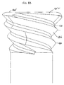
- Fig. 9 illustrates a second embodiment of an omnidirectional locking screw 500 for use through threaded holes in accordance with the present invention.
- the screw 500 includes a head 502 and a shaft 504 (which may be threaded or non-threaded).
- the head 502 includes a top surface 505 and an external thread 506.
- the top surface 505 includes a slot, hole (e.g., a square or hexagonal hole) or other structural feature (not shown) that mates to a driver that is used to forcibly insert and rotate the head 502 of the locking screw 500.
- the external thread 506 extends helically in the opposite direction relative to the internal threads of the screw holes (134, 138) of the plate 102.
- the profile of the thread 506 is spherical in shape.
- the dimensions of the reverse-hand thread 506 are selected such that the reverse-hand thread 506 self-taps into the internal thread of a screw hole (134, 138) of the plate 102 in a manner that allows the screw 500 to be secured (e.g., fixed) at an arbitrary angle within a range with respect to the axis of the given screw hole.
- the angle of thread of the internal thread of the screw holes (134, 138) and the angle of thread of the reverse-handed external thread 506 may be equal (or substantially similar) at an angle greater than 55°, for example 60°. These angles may be increased (for example, greater than 70° and more preferably 75°) for improved fixation. In alternate embodiments, these angles may be substantially different from one another.
- the reverse-handed external thread 506 of the self-tapping locking screw 500 may comprise a double thread structure as is well known in the fastening arts. This structure will overcome wobbling because it contacts the internal thread of the screw hole on opposite sides of the head 502 with opposing diametric forces as the head 502 enters the screw hole.
- the spherical profile of the thread 506 of the locking screw 500 provides a longer length of engagement that the conical profile of the thread 406 of the screw 400.
- the conical profile locks quicker than the spherical profile.
- Fig. 10 another embodiment of a surgeon directed locking screw system according to the invention is shown.
- the self-tapping external structure of the head of each surgeon-directed screw of the first set is realized by external threads 606 that runs in the same direction as the internal threads 312 of the threaded holes 134, 138 of the plate 102.
- Such external and internal threads are preferably, though not necessarily of significantly different pitch from each other.
- the threads cross-thread on purpose providing an interference fit.
- the external threads 606 may have a lesser angle of attack against the plate threads than the reverse thread screws. In fact, the external and internal threads 606, 312 can even have the same pitch and be made to cross thread by virtue of the angle of insertion.
- the head 602 of the screw 600 preferably has a conical (as indicated by broken lines) or spherical profile.
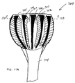
- Figs. 11A and 11B illustrate a fourth embodiment of an omnidirectional screw 700 in accordance with the present invention.
- the screw 700 includes a head 702 and a shaft 704 (which may be threaded or non-threaded).
- the head 702 includes a top surface 705 and a set of external ridges 706 and external grooves 707 that are radially spaced apart from one another about the outer circumference of the head 702 and that extend in vertical directions substantially parallel to the central axis of the screw 700 as shown.
- the profile of the ridges 705 is preferably spherical in shape as shown; however, a conical profile or other suitable profile may be used.
- the dimensions of the ridges 705 and grooves 706 are selected such that the ridges 705 are deformed by the internal thread of a screw hole (134, 138) of the plate 702 in a manner that allows the screw 700 to be secured at an arbitrary angle within a range with respect to the axis of the given screw hole. Similar to the operation of the screw 400 of Figs. 8A-8B, the angular orientation of the screw 700 is dictated by the axial direction of the insertion force applied to the head 702 by the surgeon during forcible insertion and rotation of the head 702 during the surgical operation.
- Fig. 11B shows the ridges 706 and grooves 707 spaced apart from one another about the outer circumference of the head 702. It also shows a square hole 708 that mates to a driver that is used to forcibly insert and rotate the head 702 of the locking screw 700.
- the ridges 706 may have a variable width along their extent in the vertical direction with their greatest width at top and narrowest width near the bottom of the head 702 as shown in Fig. 11A. Alternatively, the ridges 706 may have a constant width along their extent in the vertical direction.
- the material of the external contact structure (e.g., reverse-handed external thread, same hand external thread of preferably dissimilar pitch, or external ridges) of the self-tapping locking screw may be harder than the material of the internal threads of the locking screw holes of the plate.
- the internal threads of the locking screw holes may be non-anodized while the external contact structures of the locking screw are anodized. Such non-anodized internal threads may be realized by anodizing the plate 102 before drilling and tapping the threads of the screw holes therein.
- the screw hole internal thread is preferably harder than the structure (e.g., ridges) on the screw head which are intended to be deformed.
- the external contact structure cut into the plate because of geometrical configurations of the threads.
- the internal plate threads can be made relatively weaker than the screw threads by providing a relatively more acute cross section apical angle to the internal threads than the peg threads.
- the external screw threads can be trapezoidal in cross section providing greater strength by geometrical means in addition to or as opposed to being made of a harder material.
- the top part of head of the screws are preferably wider than the width of the threaded screw holes 134, 138 of the plate 102 to ensure that the heads of the screws bottom out against the surface of the plate 102 (i.e., to prevent the omnidirectional screws from being inserted completely through the threaded screw hole).
- omnidirectional self-tapping locking screws described herein are used to stabilize a fractured bone in a manner similar to the unidirectional locking screws described above.
- the same holes in the fixation plate can support both unidirectional or omnidirectional screws.
- the surgeon is afforded flexibility, ease of use, and operational efficiency.
- the omnidirectional self-tapping screws described herein are inexpensive to manufacture and provide for effective fixation at minimal costs.
- locking screw holes and locking screw are structurally adapted such that individual locking screw may be fixed at any angle within a range of angles.
- one or both sets of the locking screw may be replaced by preferably blunt tines which are integrated into the plate such that the plate and tines are unitary in construct.
- other elongate projections may be coupled to the plate to define the desired support.
- the system may also include K-wires 110, and K-wire alignment holes 140, 152a, 152b, 152c, 154 in the plate 102 (Figs. 1-6).
- K-wires 110 through K-wire alignment holes and the advantage thereof is disclosed in US-A-2004/0193165 .
- Plates having shapes other than a 'T' may also be used, such as straight plates, lateral and medial columns (generally 'L'-shaped), flared head plates, forked plates, etc.
- screw holes, locking screw holes and k-wire holes in the fixation plate may be provided in the plate, preferably such that at least two threaded screw holes preferably having axes angled in two dimensions relative to each other are provided.
- fixation plate system of the present invention utilizes cylindrical locking screw holes that are compatible with both the threaded head interface for unidirectional locking screw as well as the reverse-threaded or ridged head interface for omnidirectional locking screw, it will be appreciated that the invention can be readily extended to incorporate other compatible interface mechanisms. Similarly, different thread designs, such as double or triple threads, can be used for the locking threads of the locking screw holes, unidirectional locking screw and the omnidirectional locking screw.
Abstract
Description
- This invention relates to a bone fixation systems including plates and locking screws.
- Fracture to the metaphyseal portion of a long bone can be difficult to treat. Improper treatment can result in deformity and long-term discomfort.
- By way of example, a Colles' fracture is a fracture resulting from compressive forces being placed on the distal radius, and which causes backward or dorsal displacement of the distal fragment and radial deviation of the hand at the wrist. Often, a Colles' fracture will result in multiple bone fragments which are movable and out of alignment relative to each other. If not properly treated, such fractures may result in permanent wrist deformity and limited articulation of the wrist. It is therefore important to align the fracture and fixate the bones relative to each other so that proper healing may occur.
- Alignment and fixation of a metaphyseal fracture (occurring at the extremity of a shaft of a long bone) are typically performed by one of several methods: casting, external fixation, pinning, and plating. Casting is non-invasive, but may not be able to maintain alignment of the fracture where many bone fragments exist. Therefore, as an alternative, external fixators may be used. External fixators utilize a method known as ligamentotaxis, which provides distraction forces across the joint and permits the fracture to be aligned based upon the tension placed on the surrounding ligaments. However, while external fixators can maintain the position of the wrist bones, it may nevertheless be difficult in certain fractures to first provide the bones in proper alignment. In addition, external fixators are often not suitable for fractures resulting in multiple bone fragments. Pinning with K-wires (Kirschner wires) is an invasive procedure whereby pins are positioned into the various fragments. This is a difficult and time consuming procedure that provides limited fixation if the bone is comminuted or osteoporotic. Plating utilizes a stabilizing metal plate that is typically placed against the dorsal side of a bone. Fixators extend from the plate into holes drilled in bone fragments are used to secure the fragments to the plate and thereby provide stabilized fixation of the fragments.
- Commercially available are plates which use one of two types of fixators: (i) unidirectional fixed angle locking screws (both smooth shaft screws and threaded shaft screws) that are fixed in a predetermined orientation relative to the plate with the head of the screws threadably engaging threaded holes in the plate, and (ii) surgeon-directed or omnidirectional "locking" screws that can be fixed to the plate at any angle within a range of angles relative to the plate. The surgeon-directed "locking" screws require special structure and dedicated screw holes. All plates with surgeon-directed locking screws have the hole axes for the screws all in a parallel orientation, and generally normal to the bone contacting surface of the plate. As the angle at which any surgeon-directed locking screw can be directed is limited relative to the hole axis (generally ±15°), the range of angles through which the screws can be inserted is greatly limited. As such, such systems often suffer from an inability to properly approach the desired anatomical structure with a fixator.
- In addition, some plates additionally permit the use of, or only use, non-locking screws in which there is no direct engagement between the head of the screw and the plate, but the screw shaft engages the bone and the plate and bone are held and relationship via compression created by driving the screw. Thus, in treating a particular bone fracture, an orthopaedic surgeon is required to select one of these types of plate systems and the appropriate type of screws.
- It is believed that a fixed angle locking screw, as opposed to a non-locking screw, provides advantage over the non-locking screw in that increased stability to the fracture is provided. In addition, compression which may be disadvantageous for many fractures is avoided.
- There may be instances where improved bone stabilization and fixation can be accomplished utilizing both unidirectional and surgeon-directed locking screws. These features would allow the surgeon to better tailor the application of the plate system to the specific nature of the bone fracture suffered by the individual patient. However, no available system provides such capability.
- Accordingly, the present invention provides bone fixation system includes a substantially rigid plate defining a set of threaded holes, with preferably at least two of the threaded holes being obliquely oriented relative to each other. The system also includes a first set of at least one surgeon-directed screw which can be fixed to the plate, and optionally a second set of at least one unidirectional fixed angle locking screw having a threaded head adapted to threadably engage with the threaded hole in a conventional manner. Each respective screw of the first set has a head with an external structure that is adapted to self-tap into the internal thread of a given hole to secure the respective screw at an arbitrary surgeon selected angle within a range of permissible angles relative to the plate. This angle is defined during forcible insertion and rotation of the screw into the given hole. Thus, the use of self-tapping locking screws permits the surgeon to modify the angle of approach of a fixed angle screw relative to the respective axes of screw holes which are already obliquely oriented relative to each other.
- Preferably, the self-tapping external structure of the head of each surgeon-directed screw of the first set is realized by a reverse-hand external thread, which may have a conical or spherical profile.
- Preferably, the self-tapping external structure of the head of each surgeon-directed screw of the first set is realized by an external thread that runs in the same direction as the internal threads of the threaded holes, but such external and internal threads are of significantly different pitch from each other. The heads of these screws may have a conical or spherical profile.
- Preferably, the self-tapping external structure of the head of each surgeon-directed screw of the first set is realized by a set of external ridges and external grooves that are radially spaced apart from one another about the outer circumference of the head of the screw and that extend in vertical directions substantially parallel to the central axis of the screw. The ridges may a have constant width (or possibly a narrowing width) as they extend downward along the outer surface of the head of the screw.
- Embodiments of the invention will now be described by way of example with reference to the accompanying drawings, in which:
- Fig. 1 is a radial side elevation of a right-hand volar plate according to the invention, shown with locking screws coupled thereto;
- Fig. 2 is an ulnar side elevation of a right-hand volar plate according to the invention, shown with locking screw coupled thereto;
- Fig. 3 is top view of a right-hand volar plate according to the invention, shown with locking screws and cortical screws;
- Fig. 4 is bottom view of a right-hand volar plate according to the invention, shown with locking screws coupled thereto;
- Fig. 5 is a perspective view of a right-hand volar plate according to the invention, shown with locking screws coupled thereto and K-wires extending through body portion alignment holes and through proximal head alignment holes;
- Fig. 6 is a front end view of a right-hand volar plate according to the invention, shown with locking screws coupled thereto and K-wires extending through body portion alignment holes and proximal head alignment holes;
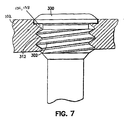
- Fig. 7 is a schematic section view of a unidirectional locking screw coupled within a threaded hole;
- Fig. 8A is a side view of a surgeon directed locking screw in accordance with the present invention.
- Fig. 8B is a side view of the head of the surgeon directed locking screw of Fig. 8A.
- Fig. 8C is a schematic illustration of a surgeon directed locking screw inserted into and securely fixed within a threaded hole of the plate of Figs. 1-6.
- Fig. 9 is a side view of the head of an alternate surgeon directed locking screw in accordance with the present invention.
- Fig. 10 is a section view of second embodiment of a surgeon directed locking screw coupled within a threaded hole according to the invention;
- Fig. 11A is a side view of the head of a third embodiment surgeon directed locking screw in accordance with the present invention.
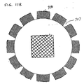
- Fig. 11B is a cross-sectional view through the head of the surgeon directed locking screw of Fig. 11A.
- Referring to the drawings, Figs. 1 to 6 show a
fracture fixation system 100 which can be used to align and to stabilise multiple bone fragments in a dorsally displaced distal radius fracture (or Colles' fracture), and also in other surgical orthopaedic bone stabilization systems for use in the treatment of this and other fractures. - The
system 100 generally includes a substantially rigid T-shaped plate 102, commonly called a volar plate, which is preferably made from a titanium alloy, such as Ti-6A1-4V. The plate includes abody 116 and ahead 118. Thesystem 100 also includes bone screws 104 (Fig. 3), a set ofunidirectional locking screws - Referring to Fig. 4, the
body 116 includes four preferably countersunk screw holes 124, 125, 126, 127 forbone screws 104 to extend through (Fig. 2). One of the screw holes, 127, is preferably generally oval in shape permitting longitudinal movement of theplate 102 relative to the shaft of a bone screw when the screw is not clamped against the plate. The screw holes may be any hole type for attaching a fixation structure, threaded or non-threaded, for coupling a cortical screw or a locking screw relative to the plate and the underlying bone. - Referring to Figs. 3 and 4, according to one preferred aspect of the
plate 102, thehead portion 118 includes a proximal first set of threaded preferably cylindrical threaded holes 134 (for placement of lockingscrews 106 and/or 108 therein) and a relatively distal second set of threaded preferably cylindrical threaded holes 138 (for placement of lockingscrew 106 and/or 108 therein). The peg holes 134 of the first set are arranged substantially parallel to a line L1 that is preferably slightly skewed (e.g., by 5°-10°) relative to a perpendicular to the longitudinal axis of thebody portion 116. Axes through the first set of peg holes are preferably oblique relative to each other, and are preferably angled relative to each other in two dimensions, generally as disclosed inUS- 6364882 . This orientation of the locking screws operates to stabilize and secure thehead 118 of theplate 102 on the bone even where such locking screws 106 do not have threaded shafts. - The second set of peg holes 138 is provided relatively distal of the first set of peg holes 134 and is most preferably primarily located in a buttress
portion 120 of the plate. Each of the peg holes 138 preferably defines an axis that is oblique relative to the other of peg holes 136 and 138. Thus, each and everypeg - Locking
screws 106 have a threaded head and a non-threaded shaft, and lockingscrews 108 have both a threaded head and at least a portion of the shaft is threaded. Suitable locking screws are disclosed inUS-6364882 . Either type of locking screw (with or without threads on the shaft), or a combination thereof, may be used at the discretion of the surgeon when the surgeon elects to implants unidirectional screws. As discussed in detail below, the surgeon may also opt to implantomnidirectional screws 400 in place of any of theunidirectional screws - Referring back to Figs. 3 and 4, axes through the first set of threaded holes 134 (indicated by the locking screws 106 extending therethrough) are preferably oblique relative to each other, and are preferably angled relative to each other in two dimensions, generally as disclosed in
US-6364882 . More particularly, the axes of theholes 134 are angled so as to extend through the subchondral bone just below and parallel to the curving articular surface of the distal radius so that, in lateral view, unidirectional locking screws extending through theholes 134 provide support for the dorsal aspect of the subchondral bone. This oblique orientation of the locking screws operates to stabilize the dorsal aspects of the subchondral bone of the articular surface relative to thehead 118 of theplate 102 even where such locking screws 106 do not have threaded shafts. - The second set of
holes 138 is provided relatively distal of the first set ofholes 134 and is most preferably primarily located in a tapered supporting buttressportion 120 of the plate. Each of theholes 138 preferably defines an axis that is oblique relative to the other ofholes 136 and 138. Thus, each and every lockingscrew respective holes holes 138 are preferably oriented relative to the axes of 134 such that locking screws 106, 108 withinholes 138 extend (or define axes which extend) between locking screws (or axes thereof) withinholes 134 in an interleaved manner which, in lateral view, defines a cradle that provides support for the central aspect of the subchondral bone of the distal radius. The oblique orientation of the locking screws provides such stabilization even where such locking screws 106 do not have threaded shafts. - Thus, the axes of the
holes - Referring to Fig. 7, in the embodiment described above, each of the
holes plate 102 has aninternal thread 312 that extends helically along the same characteristic direction (right-hand or left-handed). Theinternal thread 312 of each screw hole preferably has a cylindrical contour. Each unidirectional locking screw has ahead 300 with anexternal thread 302 that extends helically in the same direction as the internal threads of the locking screw holes 134, 138 of the plate. The threads of thehead 300 threadably engage with the preformedthreads 312 of a given screw hole. Thus, when secured in a given screw hole of the plate, the unidirectional screw extends from theplate 102 at a fixed angular orientation defined by a central axis through the helical threads of the given screw hole. - However, it is recognized and appreciated that a surgeon may wish to modify the axial approach of one or more of the locking screws based upon personal preference, or based upon the particular anatomical distinctions of a specific fracture.
- In view thereof and in accord with the invention, the
system 100 also includes the second set of locking screws 400 (Figs. 8A-8C) that are adapted to self-tap into theholes screws 400 into theholes screw 400 is structured such that it is angularly locked into position against the internal thread of the hole by an interference fit and possibly deformation of the mating structures, rather than a conventional threaded engagement of two preformed threads of the same pitch. These self-tapping locking screws are used to stabilize the fractured bone in a manner similar to the unidirectional locking screws described above. In addition, these self-tapping locking screws provide the surgeon with flexibility, ease of use, and operational efficiency in employing either unidirectional locking screw fixation or surgeon-directed fixation within the same hole. - More particularly, the use of self-tapping locking screws permits the surgeon to modify the angle of approach of a fixator relative to the axes of screw holes which are already obliquely oriented relative to each other. Thus, substantially greater range of angular diversity between the
screws 400 is possible than in the prior art. For example, where in the prior art the holes are parallel and a ±15° angular variation is permitted at any screw hole, the maximum variation between two screws is 30°. In the present invention, if two screw holes already have axes angled 30° relative to each other, given a ±15° angular variation at any screw hole, the maximum variation between two screws is 60°. Moreover, by directing the various hole axes at generally distinct and generally ideal angles for proper subchondral support, the self-tapping angular variation can be used for "fine-tuning" the angle of the screw, as opposed to gross selection of the angle. - Figs. 8A - 8B illustrate a first embodiment of a self-tapping
locking screw 400 in accordance with the present invention. The self-tappinglocking screw 400 includes ahead 402 and anon-threaded shaft 404. In an alternate embodiment (not shown), theshaft 404 may be threaded (for example, in a manner similar to the shaft of screw 108). Thehead 402 includes atop surface 405 and anexternal thread 406. Thetop surface 405 includes a slot, hole (e.g., a square or hexagonal hole) or other structural feature (not shown) that mates to a driver that is used to forcibly insert and rotate thehead 402 of the lockingscrew 400 into the screw hole to tap new threads- Theexternal thread 406 extends helically in the opposite direction relative to the internal threads of the locking screw holes 134, 136 of theplate 102. Thus,external thread 406 is referred to as "reverse-handed" or a "reverse-hand" thread. As best shown in Fig. 8B, the profile of thethread 406 is conical in shape. Such a conical profile may be formed by the crest 408 and root 410 of thethread 406 both having a conical profile wherein the conical profile of theroot 410 is offset radially inward and vertically with respect the conical profile of the crest 408. The dimensions of the reverse-hand thread 406 are selected such that the reverse-hand thread 406 self-taps into the internal thread of a screw hole (134, 138) of theplate 102 in a manner that allows thescrew 400 to be secured at the directed angle relative to the axis of the given screw hole. In the embodiment shown, the angular orientation of thescrew 400 can be set to any angle β from 0 to ±15°. - Fig. 8C illustrates another similar self-tapping
locking screw 400a secured in place in theplate 102 at an angle β of 10° relative to the axis A of the screw hole. Differences between screws 400 (Figs. 8A, 8B) and 400a (Fig. 8C) include a non-threadedupper head portion 420a (which functions as a stop to limits how far the screw head can be tapped into the screw hole), a tapered neck 422a between the head and shaft portions, and an at least partially threadedshaft 404a (to lag bone fragments). - The "angle of thread" is a feature of a thread defined by the angle between adjacent flanks (i.e., the thread surface extending between the crest and root) measured at a cross-section of the thread. The angle of thread of the internal thread of the screw holes (134,138) and the angle of thread of the reverse-handed
external thread 406 of thescrew 400 may be equal (or substantially similar) at approximately 60°. These angles may be increased (for example, greater than 70° and more preferably 75°) for improved fixation. In alternate embodiments, these angles may be substantially different from one another. - Moreover, the reverse-handed
external thread 406 of thescrew 400 may comprise a double thread structure as is well known in the fastening arts. This structure will overcome wobbling because it contacts the internal thread of the screw hole on opposite sides of thehead 402 with opposing diametric forces as thehead 402 enters the threaded screw hole. - Fig. 9 illustrates a second embodiment of an
omnidirectional locking screw 500 for use through threaded holes in accordance with the present invention. Thescrew 500 includes ahead 502 and a shaft 504 (which may be threaded or non-threaded). Thehead 502 includes atop surface 505 and anexternal thread 506. Thetop surface 505 includes a slot, hole (e.g., a square or hexagonal hole) or other structural feature (not shown) that mates to a driver that is used to forcibly insert and rotate thehead 502 of the lockingscrew 500. Theexternal thread 506 extends helically in the opposite direction relative to the internal threads of the screw holes (134, 138) of theplate 102. The profile of thethread 506 is spherical in shape. The dimensions of the reverse-hand thread 506 are selected such that the reverse-hand thread 506 self-taps into the internal thread of a screw hole (134, 138) of theplate 102 in a manner that allows thescrew 500 to be secured (e.g., fixed) at an arbitrary angle within a range with respect to the axis of the given screw hole. The angle of thread of the internal thread of the screw holes (134, 138) and the angle of thread of the reverse-handedexternal thread 506 may be equal (or substantially similar) at an angle greater than 55°, for example 60°. These angles may be increased (for example, greater than 70° and more preferably 75°) for improved fixation. In alternate embodiments, these angles may be substantially different from one another. Moreover, the reverse-handedexternal thread 506 of the self-tappinglocking screw 500 may comprise a double thread structure as is well known in the fastening arts. This structure will overcome wobbling because it contacts the internal thread of the screw hole on opposite sides of thehead 502 with opposing diametric forces as thehead 502 enters the screw hole. - Note that the spherical profile of the
thread 506 of the lockingscrew 500 provides a longer length of engagement that the conical profile of thethread 406 of thescrew 400. However, the conical profile locks quicker than the spherical profile. - Turning now to Fig. 10, another embodiment of a surgeon directed locking screw system according to the invention is shown. The self-tapping external structure of the head of each surgeon-directed screw of the first set is realized by
external threads 606 that runs in the same direction as theinternal threads 312 of the threadedholes plate 102. Such external and internal threads are preferably, though not necessarily of significantly different pitch from each other. The threads cross-thread on purpose providing an interference fit. Theexternal threads 606 may have a lesser angle of attack against the plate threads than the reverse thread screws. In fact, the external andinternal threads head 602 of thescrew 600 preferably has a conical (as indicated by broken lines) or spherical profile. - Figs. 11A and 11B illustrate a fourth embodiment of an
omnidirectional screw 700 in accordance with the present invention. Thescrew 700 includes ahead 702 and a shaft 704 (which may be threaded or non-threaded). Thehead 702 includes atop surface 705 and a set ofexternal ridges 706 andexternal grooves 707 that are radially spaced apart from one another about the outer circumference of thehead 702 and that extend in vertical directions substantially parallel to the central axis of thescrew 700 as shown. The profile of theridges 705 is preferably spherical in shape as shown; however, a conical profile or other suitable profile may be used. The dimensions of theridges 705 andgrooves 706 are selected such that theridges 705 are deformed by the internal thread of a screw hole (134, 138) of theplate 702 in a manner that allows thescrew 700 to be secured at an arbitrary angle within a range with respect to the axis of the given screw hole. Similar to the operation of thescrew 400 of Figs. 8A-8B, the angular orientation of thescrew 700 is dictated by the axial direction of the insertion force applied to thehead 702 by the surgeon during forcible insertion and rotation of thehead 702 during the surgical operation. - The cross-section of Fig. 11B shows the
ridges 706 andgrooves 707 spaced apart from one another about the outer circumference of thehead 702. It also shows a square hole 708 that mates to a driver that is used to forcibly insert and rotate thehead 702 of the lockingscrew 700. Theridges 706 may have a variable width along their extent in the vertical direction with their greatest width at top and narrowest width near the bottom of thehead 702 as shown in Fig. 11A. Alternatively, theridges 706 may have a constant width along their extent in the vertical direction. - In order to facilitate the self-tapping feature of the self-tapping locking screw described herein, the material of the external contact structure (e.g., reverse-handed external thread, same hand external thread of preferably dissimilar pitch, or external ridges) of the self-tapping locking screw may be harder than the material of the internal threads of the locking screw holes of the plate. For example, the internal threads of the locking screw holes may be non-anodized while the external contact structures of the locking screw are anodized. Such non-anodized internal threads may be realized by anodizing the
plate 102 before drilling and tapping the threads of the screw holes therein. In other embodiments where the internal threads of the screw holes deform the head of the screw to secure the screw, the screw hole internal thread is preferably harder than the structure (e.g., ridges) on the screw head which are intended to be deformed. Alternatively, the external contact structure cut into the plate because of geometrical configurations of the threads. For example, the internal plate threads can be made relatively weaker than the screw threads by providing a relatively more acute cross section apical angle to the internal threads than the peg threads. Furthermore, the external screw threads can be trapezoidal in cross section providing greater strength by geometrical means in addition to or as opposed to being made of a harder material. - For the omnidirectional self-tapping screws described herein, the top part of head of the screws are preferably wider than the width of the threaded screw holes 134, 138 of the
plate 102 to ensure that the heads of the screws bottom out against the surface of the plate 102 (i.e., to prevent the omnidirectional screws from being inserted completely through the threaded screw hole). - These omnidirectional self-tapping locking screws described herein are used to stabilize a fractured bone in a manner similar to the unidirectional locking screws described above. Advantageously, the same holes in the fixation plate (without modification or reconfiguration) can support both unidirectional or omnidirectional screws. Thus, the surgeon is afforded flexibility, ease of use, and operational efficiency. Moreover, the omnidirectional self-tapping screws described herein are inexpensive to manufacture and provide for effective fixation at minimal costs.
- While certain unidirectional locking screws (i.e., locking screws that are fixed in respective screw holes 134, 138 only in a single direction that is coaxial with the axis defined by the respective locking screw holes) as well as self-tapping omnidirectional screws have been disclosed for use in the threaded holes of the plate, it is appreciated that other locking screw systems, such as those disclosed in
US-6440135 andUS-6767351 . In such locking screw systems, the locking screw holes and locking screw are structurally adapted such that individual locking screw may be fixed at any angle within a range of angles. In addition, while less preferable, one or both sets of the locking screw may be replaced by preferably blunt tines which are integrated into the plate such that the plate and tines are unitary in construct. Similarly, other elongate projections may be coupled to the plate to define the desired support. - The system may also include K-
wires 110, and K-wire alignment holes 140, 152a, 152b, 152c, 154 in the plate 102 (Figs. 1-6). The use of K-wires 110 through K-wire alignment holes and the advantage thereof is disclosed inUS-A-2004/0193165 . - Plates having shapes other than a 'T' may also be used, such as straight plates, lateral and medial columns (generally 'L'-shaped), flared head plates, forked plates, etc. In addition, while a particular number of screw holes, locking screw holes and k-wire holes in the fixation plate have been described, it will be understood another number of holes may be provided in the plate, preferably such that at least two threaded screw holes preferably having axes angled in two dimensions relative to each other are provided. Moreover, while the fixation plate system of the present invention utilizes cylindrical locking screw holes that are compatible with both the threaded head interface for unidirectional locking screw as well as the reverse-threaded or ridged head interface for omnidirectional locking screw, it will be appreciated that the invention can be readily extended to incorporate other compatible interface mechanisms. Similarly, different thread designs, such as double or triple threads, can be used for the locking threads of the locking screw holes, unidirectional locking screw and the omnidirectional locking screw.
Claims (11)
- A bone fixation system, comprising:a substantially rigid plate having a bone contacting surface and defining a set of screw holes with internal threads, with said internal threads of said screw holes defining respective screw hole axes; anda set of a first-type of locking screws, each respective first-type of locking screws having a head with an external structure that is adapted to self-tap into the internal thread of a given locking screw hole at an oblique angle relative to said respective screw hole axis to secure said first-type of locking screws to said plate.
- A bone fixation system according to claim 1, in which at least two of said screw hole axes are oblique relative to each other.
- A bone fixation system according to claim 2, in which at least two of said screw hole axes are oblique in two dimensions relative to each other.
- A bone fixation system according to claim 2, in which the plate is a sized and shaped for the distal volar radius.
- A bone fixation system according to claim 1, which includes a set of second-type fixation locking screw, each respective second-type fixation locking screw having a head with an external thread that is adapted to threadably engage the internal thread of a given screw hole to secure the respective second-type fixation locking screw at a fixed angle relative to said plate in alignment with the respective screw hole axis.
- A bone fixation system according to claim 1, in which the external structure of each respective first-type locking screw comprises a reverse-handed external thread relative to said internal thread of said screw holes, and in which the profile of the reverse-handed external thread is preferably conical or spherical.
- A bone fixation system according to claim 6, in which the internal thread of the screw holes has a first angle of thread, and the reverse-handed external thread has a second angle of thread, the first angle of thread being substantially similar to the second angle of thread.
- A bone fixation system according to claim in which the internal threads have a first pitch, and the external structure of each respective first-type locking screw comprises an external thread having a second pitch which is greater than the first pitch.
- A bone fixation system according to claim 1, in which a top part of the head of each respective first-type locking screw is wider than the width of the screw holes.
- A bone fixation system, comprising:a substantially rigid plate having a bone contacting surface and defining a set of screw holes with internal threads, with said threads of said screw holes defining respective screw hole axes; anda set of a first-type of locking screws, each respective first-type of locking screws having a head with an external structure comprising a set of ridges and grooves that are radially spaced apart from one another about the outer circumference of said head and extending in a direction substantially parallel to an axis of the respective first-type fixation locking screw,wherein said external structure is adapted to be tapped by said internal thread of a given screw hole when inserted at an oblique angle relative to said respective screw hole axis to secure said first-type of locking screws to said plate.
- A bone fixation system, comprising:a substantially rigid plate having a bone contacting surface and defining a set of screw holes with internal threads, with said threads of said screw holes defining respective screw hole axes; anda set of a first-type of locking screws having an external thread, wherein when one of said first-type of locking screws is inserted into one of said screw holes of said plate, said internal thread and said external thread have at least one of material property and geometry facilitating said first-type of locking screw to tap its own helical path into the screw hole at an angle relative to said screw hole axis.
Applications Claiming Priority (1)
| Application Number | Priority Date | Filing Date | Title |
|---|---|---|---|
| US11/230,021 US7695502B2 (en) | 2000-02-01 | 2005-09-19 | Bone stabilization system including plate having fixed-angle holes together with unidirectional locking screws and surgeon-directed locking screws |
Publications (2)
| Publication Number | Publication Date |
|---|---|
| EP1764052A1 true EP1764052A1 (en) | 2007-03-21 |
| EP1764052B1 EP1764052B1 (en) | 2008-11-19 |
Family
ID=37591956
Family Applications (1)
| Application Number | Title | Priority Date | Filing Date |
|---|---|---|---|
| EP06254837A Not-in-force EP1764052B1 (en) | 2005-09-19 | 2006-09-18 | Bone stabilization system |
Country Status (6)
| Country | Link |
|---|---|
| US (1) | US7695502B2 (en) |
| EP (1) | EP1764052B1 (en) |
| JP (1) | JP5058541B2 (en) |
| AT (1) | ATE414478T1 (en) |
| AU (1) | AU2006220382B2 (en) |
| DE (1) | DE602006003706D1 (en) |
Cited By (5)
| Publication number | Priority date | Publication date | Assignee | Title |
|---|---|---|---|---|
| WO2011042407A1 (en) * | 2009-10-05 | 2011-04-14 | Hit Medica Spa | Device for synthesis of bone fractures |
| CN104622554A (en) * | 2013-11-12 | 2015-05-20 | 玉林市骨科医院 | Locking support for treating femoral intertrochanteric fracture through minimally invasive therapy |
| WO2017037733A1 (en) * | 2015-08-28 | 2017-03-09 | Kumar Kanojia Rajendra | External fixator for trauma management of limb |
| US10716606B2 (en) | 2012-08-23 | 2020-07-21 | DePuy Synthes Products, Inc. | Bone fixation system |
| US10772729B2 (en) | 2012-08-23 | 2020-09-15 | DePuy Synthes Products, Inc. | Bone implant |
Families Citing this family (117)
| Publication number | Priority date | Publication date | Assignee | Title |
|---|---|---|---|---|
| US6767351B2 (en) * | 2000-02-01 | 2004-07-27 | Hand Innovations, Inc. | Fixation system with multidirectional stabilization pegs |
| US6893444B2 (en) * | 2000-02-01 | 2005-05-17 | Hand Innovations, Llc | Bone fracture fixation systems with both multidirectional and unidirectional stabilization pegs |
| US20040153073A1 (en) * | 2000-02-01 | 2004-08-05 | Hand Innovations, Inc. | Orthopedic fixation system including plate element with threaded holes having divergent axes |
| US20060041260A1 (en) * | 2000-02-01 | 2006-02-23 | Orbay Jorge L | Fixation system with plate having holes with divergent axes and multidirectional fixators for use therethrough |
| US6706046B2 (en) | 2000-02-01 | 2004-03-16 | Hand Innovations, Inc. | Intramedullary fixation device for metaphyseal long bone fractures and methods of using the same |
| US7695502B2 (en) | 2000-02-01 | 2010-04-13 | Depuy Products, Inc. | Bone stabilization system including plate having fixed-angle holes together with unidirectional locking screws and surgeon-directed locking screws |
| US8518090B2 (en) | 2010-10-05 | 2013-08-27 | Acumed Llc | Fastener with serrated thread for attachment to a bone plate at a selectable angle |
| US20060149257A1 (en) * | 2002-05-30 | 2006-07-06 | Orbay Jorge L | Fracture fixation device |
| US20040111090A1 (en) * | 2002-10-03 | 2004-06-10 | The University Of North Carolina At Chapel Hill | Modification of percutaneous intrafocal plate system |
| US20050187551A1 (en) * | 2002-12-02 | 2005-08-25 | Orbay Jorge L. | Bone plate system with bone screws fixed by secondary compression |
| US7425213B2 (en) * | 2002-12-10 | 2008-09-16 | Depuy Products, Inc. | Method of endosteal nailing |
| US7951176B2 (en) | 2003-05-30 | 2011-05-31 | Synthes Usa, Llc | Bone plate |
| JP4999327B2 (en) | 2003-08-26 | 2012-08-15 | ジンテーズ ゲゼルシャフト ミト ベシュレンクテル ハフツング | Bone plate |
| US11259851B2 (en) | 2003-08-26 | 2022-03-01 | DePuy Synthes Products, Inc. | Bone plate |
| US7635365B2 (en) * | 2003-08-28 | 2009-12-22 | Ellis Thomas J | Bone plates |
| US8105367B2 (en) | 2003-09-29 | 2012-01-31 | Smith & Nephew, Inc. | Bone plate and bone plate assemblies including polyaxial fasteners |
| US11291484B2 (en) | 2004-01-26 | 2022-04-05 | DePuy Synthes Products, Inc. | Highly-versatile variable-angle bone plate system |
| US8574268B2 (en) | 2004-01-26 | 2013-11-05 | DePuy Synthes Product, LLC | Highly-versatile variable-angle bone plate system |
| US7637928B2 (en) * | 2004-01-26 | 2009-12-29 | Synthes Usa, Llc | Variable angle locked bone fixation system |
| WO2006091827A2 (en) * | 2005-02-25 | 2006-08-31 | Regents Of The University Of California | Device and template for canine humeral slide osteotomy |
| EP1919385B1 (en) | 2005-07-25 | 2014-08-20 | Smith & Nephew, Inc. | Polyaxial plates |
| US8382807B2 (en) | 2005-07-25 | 2013-02-26 | Smith & Nephew, Inc. | Systems and methods for using polyaxial plates |
| US20070023740A1 (en) * | 2005-07-29 | 2007-02-01 | Ansul, Inc. | Use of fluorinated esters in fire extinguishing compositions |
| US7905909B2 (en) | 2005-09-19 | 2011-03-15 | Depuy Products, Inc. | Bone stabilization system including multi-directional threaded fixation element |
| US7955364B2 (en) * | 2005-09-21 | 2011-06-07 | Ebi, Llc | Variable angle bone fixation assembly |
| US8029551B2 (en) * | 2006-01-10 | 2011-10-04 | Running Donald E | Fracture fixation plate with cover sheath |
| US8523921B2 (en) * | 2006-02-24 | 2013-09-03 | DePuy Synthes Products, LLC | Tibial plateau leveling osteotomy plate |
| DE602007008535D1 (en) * | 2006-03-28 | 2010-09-30 | Synthes Gmbh | FIXING BONE PLATES WITH CONTROLLED FIXING SCREW MISC |
| US8926675B2 (en) * | 2006-04-11 | 2015-01-06 | Biomet Manufacturing, Llc | Contoured bone plate |
| WO2007118317A1 (en) * | 2006-04-13 | 2007-10-25 | Arno Smit | Hip protector implant |
| GB0610630D0 (en) * | 2006-05-26 | 2006-07-05 | Ness Malcolm G | A bone fixation device |
| US10085780B2 (en) | 2006-05-26 | 2018-10-02 | Mark Richard Cunliffe | Bone fixation device |
| DE202006019220U1 (en) * | 2006-12-19 | 2007-05-24 | Zrinski Ag | Orthopedic screw fastening system for fixing at bone of patient, has through-holes cut on one another so that intersection line and surfaces are produced in direction of plate thickness, where line and surfaces co-operate with head windings |
| US20080187886A1 (en) * | 2007-02-07 | 2008-08-07 | Robb T Tait | Dental implant with constant thread crest width |
| US8870931B2 (en) * | 2007-03-21 | 2014-10-28 | The University Of North Carolina At Chapel Hill | Anti-unscrewing and multi-angular fastening apparatuses and methods for surgical bone screw/plate systems |
| US8764764B2 (en) * | 2007-03-21 | 2014-07-01 | The University Of North Carolina At Chapel Hill | Surgical plate puller devices and methods for use with surgical bone screw/plate systems |
| US20090216282A1 (en) * | 2007-05-18 | 2009-08-27 | Blake Doris M | Systems and methods for retaining a plate to a substrate with an asynchronous thread form |
| US8262706B2 (en) * | 2007-07-11 | 2012-09-11 | Stryker Trauma Gmbh | Device for creating a bone implant |
| US8317842B2 (en) | 2007-11-30 | 2012-11-27 | Biomet C.V. | Distal tibia plating system |
| WO2009091811A1 (en) | 2008-01-14 | 2009-07-23 | Brenzel Michael P | Apparatus and methods for fracture repair |
| US20090299369A1 (en) * | 2008-06-02 | 2009-12-03 | Skeletal Dynamics Llc | Hybrid Orthopedic Implant |
| US20100057086A1 (en) * | 2008-08-29 | 2010-03-04 | Zimmer, Inc. | Anodized locking plate components |
| US8814918B2 (en) | 2011-02-14 | 2014-08-26 | Skeletal Dynamics, L.L.C. | Fracture fixation plate |
| US9237910B2 (en) | 2012-01-26 | 2016-01-19 | Acute Innovations Llc | Clip for rib stabilization |
| US9775657B2 (en) | 2011-09-30 | 2017-10-03 | Acute Innovations Llc | Bone fixation system with opposed mounting portions |
| US20100168799A1 (en) * | 2008-12-29 | 2010-07-01 | Schumer Evan D | Ulnar osteotomy plate including increased compression |
| CN102355863B (en) | 2009-01-16 | 2014-09-17 | 卡波菲克斯整形有限公司 | Composite material bone implant |
| US9642662B2 (en) * | 2009-04-02 | 2017-05-09 | DePuy Synthes Products, Inc. | Locking spiral anchoring system |
| US9855082B2 (en) | 2009-05-12 | 2018-01-02 | DePuy Synthes Products, Inc. | Readjustable locking plate hole |
| US9125699B2 (en) * | 2009-05-15 | 2015-09-08 | Smith & Nephew, Inc. | Polyaxial fastener systems and methods |
| US8823749B2 (en) | 2009-06-10 | 2014-09-02 | Qualcomm Incorporated | User interface methods providing continuous zoom functionality |
| US8758346B2 (en) * | 2009-09-14 | 2014-06-24 | DePuy Synthes Products, LLC | Variable angle compression plate |
| EP2954870B1 (en) * | 2009-09-18 | 2018-04-25 | Biomet C.V. | Disposable orthopaedic surgery kit and components |
| US10390867B2 (en) | 2009-09-18 | 2019-08-27 | Biomet C.V. | Bone plate system and method |
| US8496692B2 (en) * | 2009-09-21 | 2013-07-30 | Jmea Corporation | Locking securing member |
| DE102009049168A1 (en) * | 2009-10-12 | 2011-04-28 | Normed Medizin-Technik Gmbh | Bone screw and system |
| US8568417B2 (en) | 2009-12-18 | 2013-10-29 | Charles River Engineering Solutions And Technologies, Llc | Articulating tool and methods of using |
| WO2011088172A1 (en) | 2010-01-15 | 2011-07-21 | Brenzel Michael P | Rotary-rigid orthopaedic rod |
| AU2011207550B2 (en) | 2010-01-20 | 2016-03-10 | Conventus Orthopaedics, Inc. | Apparatus and methods for bone access and cavity preparation |
| WO2011112619A1 (en) * | 2010-03-08 | 2011-09-15 | Krinke Todd A | Apparatus and methods for bone repair |
| FR2956972B1 (en) | 2010-03-08 | 2012-12-28 | Memometal Technologies | ARTICULATED OSTEOSYNTHESIS PLATE |
| EP2544608A4 (en) | 2010-03-08 | 2017-02-22 | Conventus Orthopaedics, Inc. | Apparatus and methods for securing a bone implant |
| FR2956971B1 (en) | 2010-03-08 | 2012-03-02 | Memometal Technologies | PLATE OSTEOSYNTHESIS SYSTEM |
| US20110218580A1 (en) | 2010-03-08 | 2011-09-08 | Stryker Trauma Sa | Bone fixation system with curved profile threads |
| US8603148B2 (en) | 2010-05-07 | 2013-12-10 | Raymond B. Raven, III | System for treating bone fractures |
| CN105167830B (en) | 2010-06-07 | 2018-06-12 | 卡波菲克斯整形有限公司 | Composite material bone implant |
| US10154867B2 (en) | 2010-06-07 | 2018-12-18 | Carbofix In Orthopedics Llc | Multi-layer composite material bone screw |
| US8753396B1 (en) | 2010-09-13 | 2014-06-17 | Theken Spine, Llc | Intervertebral implant having back-out prevention feature |
| WO2012079007A2 (en) * | 2010-12-09 | 2012-06-14 | Dentatus, Usa, Ltd. | Cross-ridge implant, drill, and method for implantation |
| US8709092B2 (en) | 2011-02-16 | 2014-04-29 | Genesis Medical Devices, LLC | Periprosthetic fracture management enhancements |
| RU2013158111A (en) | 2011-06-15 | 2015-07-20 | Смит Энд Нефью, Инк. | IMPLANT WITH A VARIABLE ANGLE OF FIXATION |
| US9526549B2 (en) | 2012-01-16 | 2016-12-27 | Carbofix Orthopedics Ltd. | Bone screw with insert |
| EP2614787B1 (en) * | 2012-01-16 | 2017-03-15 | Carbofix Orthopedics Ltd. | Multi-axial bone plate fixation |
| US9387022B2 (en) | 2012-06-27 | 2016-07-12 | DePuy Synthes Products, Inc. | Variable angle bone fixation device |
| US9265542B2 (en) | 2012-06-27 | 2016-02-23 | DePuy Synthes Products, Inc. | Variable angle bone fixation device |
| JP5960546B2 (en) * | 2012-08-16 | 2016-08-02 | ミズホ株式会社 | Fracture treatment plate |
| IN2015DN01479A (en) * | 2012-08-23 | 2015-07-03 | Synthes Gmbh | |
| CN108158643A (en) | 2012-08-23 | 2018-06-15 | 新特斯有限责任公司 | Bone implant |
| US20140066998A1 (en) * | 2012-09-06 | 2014-03-06 | Jean-Jacques Martin | Assembly comprising an implantable part designed to be fastened to one or more bones or bone portions to be joined, and at least one screw for fastening the implantable part to said bone(s) |
| DE202014011161U1 (en) | 2013-01-15 | 2018-03-21 | Zimmer Gmbh | Surgical bone screw and implantation system |
| US9433454B2 (en) | 2013-03-14 | 2016-09-06 | Amei Technologies, Inc. | Variable angle screws, plates and systems |
| US9510880B2 (en) | 2013-08-13 | 2016-12-06 | Zimmer, Inc. | Polyaxial locking mechanism |
| DE102013109569A1 (en) | 2013-09-02 | 2015-03-05 | Aesculap Ag | Bone screws, implant plate and system thereof |
| AU2014321392B2 (en) | 2013-09-19 | 2018-11-08 | Mcginley Engineered Solutions, Llc | Variable angle blade plate system and method |
| JP2015077300A (en) * | 2013-10-17 | 2015-04-23 | ミズホ株式会社 | Bone anchoring device |
| CN105939677A (en) | 2013-12-12 | 2016-09-14 | 康文图斯整形外科公司 | Tissue displacement tools and methods |
| US10869704B2 (en) | 2014-06-30 | 2020-12-22 | DePuy Synthes Products, Inc. | Metacarpal neck plate |
| JP6735529B2 (en) * | 2014-07-09 | 2020-08-05 | 国立大学法人東海国立大学機構 | Locking plate system for the treatment of distal radius fractures |
| WO2016008587A1 (en) | 2014-07-18 | 2016-01-21 | Sartorius Stedim Biotech Gmbh | Membrane with increased surface area |
| JP2017532141A (en) * | 2014-10-24 | 2017-11-02 | オーストフィックス グループ リミテッド | Bone fixation system and plate therefor |
| US11076898B2 (en) | 2015-08-27 | 2021-08-03 | Globus Medical, Inc. | Proximal humeral stabilization system |
| US11197682B2 (en) | 2015-08-27 | 2021-12-14 | Globus Medical, Inc. | Proximal humeral stabilization system |
| US10687874B2 (en) * | 2015-08-27 | 2020-06-23 | Globus Medical, Inc | Proximal humeral stabilization system |
| GB2557840B (en) | 2015-09-18 | 2021-07-21 | Smith & Nephew Inc | Bone plate |
| US10617458B2 (en) | 2015-12-23 | 2020-04-14 | Carbofix In Orthopedics Llc | Multi-layer composite material bone screw |
| DE102015122793A1 (en) * | 2015-12-23 | 2017-06-29 | Karl Leibinger Medizintechnik Gmbh & Co. Kg | Implant for bone augmentation with Bohrvektorvorgabeloch and Umgriffsplatte for jaw replacement and Implantatstellverfahren |
| US10687873B2 (en) | 2016-08-17 | 2020-06-23 | Globus Medical Inc. | Stabilization systems |
| US11331128B2 (en) | 2016-08-17 | 2022-05-17 | Globus Medical Inc. | Distal radius stabilization system |
| US10383668B2 (en) * | 2016-08-17 | 2019-08-20 | Globus Medical, Inc. | Volar distal radius stabilization system |
| US11213327B2 (en) * | 2016-08-17 | 2022-01-04 | Globus Medical, Inc. | Fracture plates, systems, and methods |
| US11141204B2 (en) | 2016-08-17 | 2021-10-12 | Globus Medical Inc. | Wrist stabilization systems |
| US10420596B2 (en) * | 2016-08-17 | 2019-09-24 | Globus Medical, Inc. | Volar distal radius stabilization system |
| US10575884B2 (en) * | 2016-08-17 | 2020-03-03 | Globus Medical, Inc. | Fracture plates, systems, and methods |
| US10624686B2 (en) | 2016-09-08 | 2020-04-21 | DePuy Synthes Products, Inc. | Variable angel bone plate |
| US10905476B2 (en) | 2016-09-08 | 2021-02-02 | DePuy Synthes Products, Inc. | Variable angle bone plate |
| US10820930B2 (en) | 2016-09-08 | 2020-11-03 | DePuy Synthes Products, Inc. | Variable angle bone plate |
| FR3058312B1 (en) * | 2016-11-04 | 2019-05-10 | Neosteo | BONE POLYAXIAL FIXATION ASSEMBLY |
| US10631881B2 (en) | 2017-03-09 | 2020-04-28 | Flower Orthopedics Corporation | Plating depth gauge and countersink instrument |
| US10918426B2 (en) | 2017-07-04 | 2021-02-16 | Conventus Orthopaedics, Inc. | Apparatus and methods for treatment of a bone |
| EP4108194A1 (en) | 2018-03-02 | 2022-12-28 | Stryker European Holdings I, LLC | Bone plates and associated screws |
| US11026727B2 (en) | 2018-03-20 | 2021-06-08 | DePuy Synthes Products, Inc. | Bone plate with form-fitting variable-angle locking hole |
| US10772665B2 (en) | 2018-03-29 | 2020-09-15 | DePuy Synthes Products, Inc. | Locking structures for affixing bone anchors to a bone plate, and related systems and methods |
| US11013541B2 (en) * | 2018-04-30 | 2021-05-25 | DePuy Synthes Products, Inc. | Threaded locking structures for affixing bone anchors to a bone plate, and related systems and methods |
| JP2019055232A (en) * | 2018-11-27 | 2019-04-11 | 国立大学法人名古屋大学 | Rocking plate system for treatment of radius distal end fracture |
| US10925651B2 (en) | 2018-12-21 | 2021-02-23 | DePuy Synthes Products, Inc. | Implant having locking holes with collection cavity for shavings |
| US11179180B2 (en) | 2019-06-11 | 2021-11-23 | DePuy Synthes Products, Inc. | Deformable threaded locking structures, and related systems and methods |
| US11944360B2 (en) | 2019-06-11 | 2024-04-02 | DePuy Synthes Products, Inc. | Deformable threaded locking structures, and related systems and methods |
Citations (6)
| Publication number | Priority date | Publication date | Assignee | Title |
|---|---|---|---|---|
| DE19629011A1 (en) * | 1996-07-18 | 1998-01-22 | Wolter Dietmar Prof Dr Med | Auxiliary for promoting osteo-synthesis |
| US20040073218A1 (en) * | 2002-10-15 | 2004-04-15 | The University Of North Carolina At Chapel Hill | Multi-angular fastening apparatus and method for surgical bone screw/plate systems |
| WO2004032751A2 (en) * | 2002-10-09 | 2004-04-22 | Biotech International (Sarl) | Self-locking osteosynthesis device |
| US20040193163A1 (en) * | 2003-03-27 | 2004-09-30 | Orbay Jorge L. | Bone fracture fixation system with subchondral and articular surface support |
| FR2855391A1 (en) * | 2003-05-30 | 2004-12-03 | Xavier Renard | AUTO COMPRESSIVE SCREW TO JOIN TWO PORTIONS OF BONE |
| US20060009771A1 (en) * | 2000-02-01 | 2006-01-12 | Orbay Jorge L | Bone stabilization system including plate having fixed-angle holes together with unidirectional locking screws and surgeon-directed locking screws |
Family Cites Families (204)
| Publication number | Priority date | Publication date | Assignee | Title |
|---|---|---|---|---|
| US388000A (en) | 1888-08-14 | Half to chaeles h | ||
| US472913A (en) | 1892-04-12 | Nail or spike | ||
| US1151861A (en) | 1914-05-23 | 1915-08-31 | Ernest M Brumback | Countersinking screw-head. |
| US2056688A (en) | 1934-11-15 | 1936-10-06 | Lamson & Sessions Co | Weather-tight bolt |
| US2500370A (en) | 1947-06-30 | 1950-03-14 | Mckibbin Genevieve | Repair of femur fracture |
| US2526959A (en) | 1947-07-01 | 1950-10-24 | Frank A Lorenzo | Fracture reduction apparatus |
| US3025853A (en) | 1958-07-07 | 1962-03-20 | Christopher A Mason | Fixation device for fractured femur |
| US3236141A (en) | 1963-11-05 | 1966-02-22 | Robert D Smith | Screw |
| USRE28841E (en) | 1966-06-22 | 1976-06-08 | Synthes A.G. | Osteosynthetic pressure plate construction |
| US3645161A (en) | 1969-11-18 | 1972-02-29 | Pic Design Corp | Solder tip setscrew |
| US3709218A (en) | 1970-04-24 | 1973-01-09 | W Halloran | Combination intramedullary fixation and external bone compression apparatus |
| US3717146A (en) | 1971-02-01 | 1973-02-20 | W Halloran | Threaded intramedullary compression and fixation device |
| US3741205A (en) | 1971-06-14 | 1973-06-26 | K Markolf | Bone fixation plate |
| US3842825A (en) | 1973-11-12 | 1974-10-22 | R Wagner | Hip fixation device |
| GB1515293A (en) | 1974-05-29 | 1978-06-21 | Nat Res Dev | Endoprosthetic devices |
| GB1571713A (en) | 1976-04-21 | 1980-07-16 | Gil J L | Apparatus for use in the treatment of bone fractures |
| US4011863A (en) | 1976-07-19 | 1977-03-15 | Zickel Robert E | Supracondylar prosthetic nail |
| ZA771690B (en) | 1977-04-21 | 1978-06-28 | C Grobbelaar | Improved hip joint |
| US4135507A (en) | 1977-05-20 | 1979-01-23 | Harris Leslie J | Condylocephalic nail for fixation of pertrochanteric fractures |
| US4169470A (en) | 1977-10-19 | 1979-10-02 | Ender Hans G | Surgical nail for use in setting bone fractures, and tool for emplacing same |
| US4172452A (en) | 1978-05-15 | 1979-10-30 | Howmedica, Inc. | Fracture nail plate assembly |
| AT366254B (en) | 1979-12-14 | 1982-03-25 | Ender Josef | INSTRUMENTARIUM FOR THE REPOSITION AND FIXATION OF PER- AND SUBTROCHANTER FRACTURES, AS WELL AS A PART OF THIS INSTRUMENTARY ITEM |
| CH645013A5 (en) | 1980-04-14 | 1984-09-14 | Wenk Wilh Ag | Osteosynthetic COMPRESSION PLATE. |
| CH648197A5 (en) | 1980-05-28 | 1985-03-15 | Synthes Ag | IMPLANT AND SCREW FASTENING ON ITS BONE. |
| CH651192A5 (en) | 1980-11-20 | 1985-09-13 | Synthes Ag | OSTEOSYNTHETIC DEVICE AND CORRESPONDING DRILL GAUGE. |
| CA1178150A (en) | 1981-06-18 | 1984-11-20 | Emmanuel Anapliotis | Nail for fixing a fracture of the femur |
| SE424139B (en) | 1981-07-17 | 1982-07-05 | Lars Kolmert | DEVICE FOR CONNECTING SPRING NAILS AND CROSS-SCREWS IN THE FIXATION OF BONE FRACTURES |
| FR2519857A1 (en) | 1982-01-19 | 1983-07-22 | Butel Jean | DEVICE FOR OSTEOSYNTHESIS OF THE FRACTURES OF THE END OF THE FEMUR |
| DE8214493U1 (en) | 1982-05-18 | 1982-09-09 | Howmedica International, Inc. Zweigniederlassung Kiel, 2301 Schönkirchen | Bone nail for the treatment of fractures in the proximal thigh area |
| FR2527921A1 (en) | 1982-06-02 | 1983-12-09 | Tornier Sa | IMPROVEMENTS IN THE NAILS FOR THE OSTEOSYNTHESIS OF THE FRACTURES OF FEMALE COLLARS |
| AT378324B (en) | 1982-09-13 | 1985-07-25 | Streli Elke | TINNED PLATE FOR FIXING THE BONES IN THE BODIES IN BONE BREAKS |
| GB2158716B (en) | 1984-05-18 | 1987-09-30 | Technomed Gmk | Bone joining plate |
| RO89820B1 (en) | 1985-11-05 | 2002-06-28 | îNTREPRINDEREA INDUSTRIA TEHNICO MEDICALA | Elastic implants for a stable elastic osteorrhaphy of femoral and tibial fractures, respectively, as well as corresponding instrumentation |
| SE460014B (en) | 1986-01-31 | 1989-09-04 | John Stefan Nilsson | FIXATION DEVICE FOR LABOR FRACTURES |
| PL147580B1 (en) | 1986-04-14 | 1989-06-30 | Plate for uniting epiphysis and diaphysis of broken bone | |
| US4733654A (en) | 1986-05-29 | 1988-03-29 | Marino James F | Intramedullar nailing assembly |
| US4776330A (en) | 1986-06-23 | 1988-10-11 | Pfizer Hospital Products Group, Inc. | Modular femoral fixation system |
| US5190544A (en) | 1986-06-23 | 1993-03-02 | Pfizer Hospital Products Group, Inc. | Modular femoral fixation system |
| AT387711B (en) | 1986-07-15 | 1989-03-10 | David Thomas | BONE FIXATION PLATE |
| US5151103A (en) | 1987-11-03 | 1992-09-29 | Synthes (U.S.A.) | Point contact bone compression plate |
| US4955886A (en) | 1988-04-01 | 1990-09-11 | The Trustees Of Columbia University In The City Of New York | Dual-taper, asymmetric hole placement in reconstruction and fracture plates |
| CH675531A5 (en) | 1988-04-29 | 1990-10-15 | Synthes Ag | Instrument for osteosynthesis with perforated plate - has convex head bone screws fitting in tapering holes in osteosynthesis plate |
| DE3840798A1 (en) | 1988-12-01 | 1990-06-21 | Mecron Med Prod Gmbh | MARKING NAIL |
| FR2642958A1 (en) | 1989-02-16 | 1990-08-17 | Louyot Comptoir Lyon Alemand | SYSTEM FOR IMPLEMENTING SURGICAL INTERVENTIONS, SUCH AS THE TREATMENT OF FRACTURES OF THE VERTEBRAL COLUMN OR OF DEGENERATIVE OR TUMORAL LESIONS |
| DE3923995A1 (en) | 1989-07-20 | 1991-01-31 | Lutz Biedermann | BONE STABILIZING ELEMENT |
| US5006120A (en) | 1989-10-10 | 1991-04-09 | Carter Peter R | Distal radial fracture set and method for repairing distal radial fractures |
| US4923471A (en) | 1989-10-17 | 1990-05-08 | Timesh, Inc. | Bone fracture reduction and fixation devices with identity tags |
| CH683065A5 (en) | 1990-03-20 | 1994-01-14 | Synthes Ag | Tibial intramedullary nail with adapted cross-section. |
| CH685422A5 (en) | 1990-04-10 | 1995-07-14 | Sulzer Ag | An anchoring stem for a femoral head prosthesis. |
| US5015248A (en) | 1990-06-11 | 1991-05-14 | New York Society For The Relief Of The Ruptured & Crippled, Maintaining The Hospital For Special Surgery | Bone fracture fixation device |
| US5127912A (en) | 1990-10-05 | 1992-07-07 | R. Charles Ray | Sacral implant system |
| US5300073A (en) | 1990-10-05 | 1994-04-05 | Salut, Ltd. | Sacral implant system |
| US5085660A (en) | 1990-11-19 | 1992-02-04 | Lin Kwan C | Innovative locking plate system |
| US5486176A (en) | 1991-03-27 | 1996-01-23 | Smith & Nephew Richards, Inc. | Angled bone fixation apparatus |
| US5275601A (en) | 1991-09-03 | 1994-01-04 | Synthes (U.S.A) | Self-locking resorbable screws and plates for internal fixation of bone fractures and tendon-to-bone attachment |
| DE9114118U1 (en) | 1991-11-13 | 1992-01-02 | Howmedica Gmbh, 2314 Schoenkirchen, De | |
| US5356410A (en) | 1991-12-13 | 1994-10-18 | Dietmar Pennig | Adjuvant for osteosynthesis in the case of pertrochanteric fracture of the neck of the femur |
| US5304180A (en) | 1992-01-17 | 1994-04-19 | Slocum D Barclay | Tibial osteotomy fixation plate |
| US5201733A (en) | 1992-01-21 | 1993-04-13 | Etheredge Iii James L | Method and apparatus for internal fixation of fractures |
| DE4205118C1 (en) | 1992-02-13 | 1993-07-29 | Dietmar Dr.Med. Priv. Doz. 5000 Koeln De Pennig | |
| GB9206018D0 (en) | 1992-03-19 | 1992-04-29 | Dall Desmond Meiring | Bone fixation system |
| DE4209122A1 (en) | 1992-03-20 | 1993-09-23 | Kessler Sigurd | MARKING NAIL |
| US5356253A (en) | 1992-04-29 | 1994-10-18 | Whitesell Neil L | Sheet metal screw |
| US5197966A (en) | 1992-05-22 | 1993-03-30 | Sommerkamp T Greg | Radiodorsal buttress blade plate implant for repairing distal radius fractures |
| FR2693899B1 (en) | 1992-07-24 | 1994-09-23 | Laboureau Jacques | Osteosynthesis plate clip. |
| US5382248A (en) | 1992-09-10 | 1995-01-17 | H. D. Medical, Inc. | System and method for stabilizing bone segments |
| WO1994010947A1 (en) | 1992-11-10 | 1994-05-26 | Innovative Orthopaedics Manufacturing, Inc. | Dynamic external fixator for the wrist |
| EP0599640B1 (en) | 1992-11-25 | 1998-08-26 | CODMAN & SHURTLEFF INC. | Osteosynthesis plate system |
| US5665087A (en) | 1996-03-26 | 1997-09-09 | Huebner; Randall J. | Method and screw for repair of olecranon fractures |
| US5364399A (en) | 1993-02-05 | 1994-11-15 | Danek Medical, Inc. | Anterior cervical plating system |
| US5531745A (en) | 1993-03-11 | 1996-07-02 | Danek Medical, Inc. | System for stabilizing the spine and reducing spondylolisthesis |
| IL105183A (en) | 1993-03-28 | 1996-07-23 | Yehiel Gotfried | Surgical device for connection of fractured bones |
| US5352228A (en) | 1993-05-10 | 1994-10-04 | Kummer Frederick J | Apparatus and method to provide compression for a locked intramedullary nail |
| US5352229A (en) | 1993-05-12 | 1994-10-04 | Marlowe Goble E | Arbor press staple and washer and method for its use |
| US5458654A (en) | 1993-07-14 | 1995-10-17 | Ao-Forschungsinstitut Davos | Screw-fixed femoral component for hip joint prosthesis |
| FR2711505B1 (en) | 1993-10-25 | 1995-12-29 | Tornier Sa | Device for synthesizing fractures of the upper end of the femur. |
| DE9321544U1 (en) | 1993-12-09 | 1999-09-23 | Koenigsee Implantate & Instr | Osteosynthetic plate |
| US5558674A (en) | 1993-12-17 | 1996-09-24 | Smith & Nephew Richards, Inc. | Devices and methods for posterior spinal fixation |
| DE4343117C2 (en) | 1993-12-17 | 1999-11-04 | Dietmar Wolter | Bone fixation system |
| EP0668059B1 (en) | 1994-02-21 | 2000-01-05 | Collux AB | Implant for treating fractures of the femur |
| US5472444A (en) | 1994-05-13 | 1995-12-05 | Acumed, Inc. | Humeral nail for fixation of proximal humeral fractures |
| JP3441513B2 (en) | 1994-05-20 | 2003-09-02 | ペンタックス株式会社 | Mounting jig for intramedullary nail |
| CA2144353C (en) | 1994-05-24 | 2001-08-21 | Slobodan Tepic | Bone plate |
| DE4423210A1 (en) | 1994-07-01 | 1996-01-04 | Sigurd Dr Kesler | Fixation and positioning system for intramedullary force carriers |
| US5601553A (en) | 1994-10-03 | 1997-02-11 | Synthes (U.S.A.) | Locking plate and bone screw |
| US5536127A (en) | 1994-10-13 | 1996-07-16 | Pennig; Dietmar | Headed screw construction for use in fixing the position of an intramedullary nail |
| US5586985A (en) | 1994-10-26 | 1996-12-24 | Regents Of The University Of Minnesota | Method and apparatus for fixation of distal radius fractures |
| SE505452C2 (en) | 1995-02-14 | 1997-09-01 | Robert J Medoff | An implantable fragment clip / support and method of making it |
| SE508120C2 (en) | 1995-01-27 | 1998-08-31 | Robert J Medoff | Implantable device comprising a pin plate and pins |
| US5941878A (en) | 1995-02-14 | 1999-08-24 | Medoff; Robert J. | Implantable, surgical buttressing device |
| DE29504857U1 (en) | 1995-03-22 | 1995-05-18 | Aesculap Ag | Drilling jig for surgical drilling tools |
| US5709686A (en) | 1995-03-27 | 1998-01-20 | Synthes (U.S.A.) | Bone plate |
| US6780186B2 (en) | 1995-04-13 | 2004-08-24 | Third Millennium Engineering Llc | Anterior cervical plate having polyaxial locking screws and sliding coupling elements |
| US5520690A (en) | 1995-04-13 | 1996-05-28 | Errico; Joseph P. | Anterior spinal polyaxial locking screw plate assembly |
| US5578035A (en) | 1995-05-16 | 1996-11-26 | Lin; Chih-I | Expandable bone marrow cavity fixation device |
| DE59509247D1 (en) | 1995-09-06 | 2001-06-13 | Synthes Ag | BONE PLATE |
| US5749872A (en) | 1995-09-08 | 1998-05-12 | Ace Medical Company | Keyed/keyless barrel for bone plates |
| US5766174A (en) | 1995-09-26 | 1998-06-16 | Orthologic Corporation | Intramedullary bone fixation device |
| US6146384A (en) | 1995-10-13 | 2000-11-14 | Sdgi Holdings, Inc. | Orthopedic fixation device and method of implantation |
| DE19542116A1 (en) | 1995-11-11 | 1997-05-15 | Peter Brehm | Device for fixing implant to bone |
| US5676667A (en) | 1995-12-08 | 1997-10-14 | Hausman; Michael | Bone fixation apparatus and method |
| DE19548395A1 (en) | 1995-12-22 | 1997-09-18 | Leibinger Gmbh | Osteosynthesis device |
| US6007535A (en) | 1996-01-03 | 1999-12-28 | John M. Rayhack | Multi-plane bone distraction system |
| US5868749A (en) | 1996-04-05 | 1999-02-09 | Reed; Thomas M. | Fixation devices |
| CA2174293C (en) | 1996-04-16 | 2002-05-28 | Robert John Runciman | Reconstruction bone plate |
| US5776194A (en) | 1996-04-25 | 1998-07-07 | Nuvana Medical Innovations, Llc | Intermedullary rod apparatus and methods of repairing proximal humerus fractures |
| DE19617745C2 (en) | 1996-05-03 | 2002-06-13 | Heidelberger Druckmasch Ag | Printing machine cylinder with a corrosion protection layer, and method for producing such |
| FR2748387B1 (en) | 1996-05-13 | 1998-10-30 | Stryker France Sa | BONE FIXATION DEVICE, IN PARTICULAR TO THE SACRUM, IN OSTEOSYNTHESIS OF THE SPINE |
| WO1997047251A1 (en) | 1996-06-14 | 1997-12-18 | Depuy Ace Medical Company | Upper extremity bone plate |
| US5718705A (en) | 1996-07-16 | 1998-02-17 | Sammarco; Giacomo J. | Internal fixation plate |
| DE29615482U1 (en) | 1996-09-05 | 1998-01-08 | Howmedica Gmbh | Supracondylar bone nail |
| US5879350A (en) | 1996-09-24 | 1999-03-09 | Sdgi Holdings, Inc. | Multi-axial bone screw assembly |
| ATE224675T1 (en) | 1996-12-02 | 2002-10-15 | Synthes Ag | FLAT INTEGRAL NAIL |
| ES2299202T3 (en) | 1997-02-11 | 2008-05-16 | Warsaw Orthopedic, Inc. | SCHEMETIC PLATE SYSTEM. |
| JP4467647B2 (en) | 1997-02-11 | 2010-05-26 | ウォーソー・オーソペディック・インコーポレーテッド | Bone plating system |
| US5827286A (en) | 1997-02-14 | 1998-10-27 | Incavo; Stephen J. | Incrementally adjustable tibial osteotomy fixation device and method |
| US5935128A (en) | 1997-04-18 | 1999-08-10 | Bristol-Myers Squibb Co. | Orthopaedic template system including a joint locator |
| US5853413A (en) | 1997-04-18 | 1998-12-29 | Bristol-Myers Squibb Company | Wrist fusion plate |
| ZA983955B (en) | 1997-05-15 | 2001-08-13 | Sdgi Holdings Inc | Anterior cervical plating system. |
| US5785711A (en) | 1997-05-15 | 1998-07-28 | Third Millennium Engineering, Llc | Polyaxial pedicle screw having a through bar clamp locking mechanism |
| US5989254A (en) | 1997-05-20 | 1999-11-23 | Katz; Akiva Raphael | Pedicle screw assembly |
| US6228285B1 (en) | 1997-06-04 | 2001-05-08 | The University Of Dayton | Method for processing rigid-chain polymers into structural materials |
| US5851207A (en) | 1997-07-01 | 1998-12-22 | Synthes (U.S.A.) | Freely separable surgical drill guide and plate |
| US6123709A (en) | 1997-07-25 | 2000-09-26 | Jones; Andrew R. | Bone buttress plate and method of using same |
| US5954722A (en) | 1997-07-29 | 1999-09-21 | Depuy Acromed, Inc. | Polyaxial locking plate |
| US6454769B2 (en) | 1997-08-04 | 2002-09-24 | Spinal Concepts, Inc. | System and method for stabilizing the human spine with a bone plate |
| JP3596809B2 (en) | 1997-09-04 | 2004-12-02 | ジンテーズ アクチエンゲゼルシャフト クール | Symmetric bone plate |
| CA2303853C (en) | 1997-09-24 | 2007-01-30 | Depuy Orthopaedics, Inc. | Acl fixation pin and method |
| EP1024762B1 (en) | 1997-10-20 | 2003-07-30 | SYNTHES AG Chur | Bone fixation device |
| EP1027005A1 (en) | 1997-10-24 | 2000-08-16 | Robert S. Bray, Jr. | Bone plate and bone screw guide mechanism |
| DE19750493A1 (en) | 1997-11-14 | 1999-06-02 | Medos Medizintechnik Gmbh | Fracture stabilization implant and screw for use in surgery |
| US5951557A (en) | 1997-12-30 | 1999-09-14 | Luter; Dennis W. | Bone plate |
| US6045551A (en) | 1998-02-06 | 2000-04-04 | Bonutti; Peter M. | Bone suture |
| US7052499B2 (en) | 1998-02-18 | 2006-05-30 | Walter Lorenz Surgical, Inc. | Method and apparatus for bone fracture fixation |
| US5938664A (en) | 1998-03-31 | 1999-08-17 | Zimmer, Inc. | Orthopaedic bone plate |
| US6010503A (en) | 1998-04-03 | 2000-01-04 | Spinal Innovations, Llc | Locking mechanism |
| US6533786B1 (en) | 1999-10-13 | 2003-03-18 | Sdgi Holdings, Inc. | Anterior cervical plating system |
| DE69916045T2 (en) | 1998-05-12 | 2004-08-05 | Boston Scientific Ltd., St. Michael | HAND-OPERATED BONE ANCHOR SETTING DEVICE |
| US6258089B1 (en) | 1998-05-19 | 2001-07-10 | Alphatec Manufacturing, Inc. | Anterior cervical plate and fixation system |
| US5968046A (en) | 1998-06-04 | 1999-10-19 | Smith & Nephew, Inc. | Provisional fixation pin |
| DE19832513A1 (en) | 1998-07-20 | 2000-02-17 | Impag Gmbh Medizintechnik | Fastening arrangement |
| AT406011B (en) | 1998-07-30 | 2000-01-25 | Stoffella Rudolf Dr | Implant for fixing two bone fragments to each other |
| US6296642B1 (en) * | 1998-11-09 | 2001-10-02 | Sdgi Holdings, Inc. | Reverse angle thread for preventing splaying in medical devices |
| US6183475B1 (en) | 1998-12-18 | 2001-02-06 | Sulzer Orthopedics Inc. | Distal femoral osteotomy system and method |
| DE19858889B4 (en) * | 1998-12-19 | 2008-08-07 | Wolter, Dietmar, Prof. Dr.Med. | Fixation system for bones |
| US6129730A (en) | 1999-02-10 | 2000-10-10 | Depuy Acromed, Inc. | Bi-fed offset pitch bone screw |
| US6355043B1 (en) | 1999-03-01 | 2002-03-12 | Sulzer Orthopedics Ltd. | Bone screw for anchoring a marrow nail |
| ES2224606T3 (en) | 1999-03-09 | 2005-03-01 | Synthes Ag Chur | PLATE FOR OSTEOSYNTHESIS. |
| US6730091B1 (en) * | 1999-05-03 | 2004-05-04 | Medartis Ag | Blockable bone plate |
| US7008425B2 (en) | 1999-05-27 | 2006-03-07 | Jonathan Phillips | Pediatric intramedullary nail and method |
| US6221073B1 (en) | 1999-08-20 | 2001-04-24 | Kinetikos Medical, Inc. | Wrist fusion apparatus and method |
| DK1211992T3 (en) | 1999-09-13 | 2004-05-10 | Synthes Ag | Bone Plate System |
| AU7420000A (en) | 1999-09-14 | 2001-04-17 | Dietmar Wolter | Fixation system for bones |
| AU1493301A (en) | 1999-09-27 | 2001-04-30 | Blackstone Medical, Inc. | A surgical screw system and related methods |
| US6692503B2 (en) | 1999-10-13 | 2004-02-17 | Sdgi Holdings, Inc | System and method for securing a plate to the spinal column |
| US6712820B2 (en) | 2000-02-01 | 2004-03-30 | Hand Innovations, Inc. | Fixation plate system for dorsal wrist fracture fixation |
| US6358250B1 (en) | 2000-02-01 | 2002-03-19 | Hand Innovations, Inc. | Volar fixation system |
| US6440135B2 (en) | 2000-02-01 | 2002-08-27 | Hand Innovations, Inc. | Volar fixation system with articulating stabilization pegs |
| US6730090B2 (en) | 2000-02-01 | 2004-05-04 | Hand Innovations, Inc. | Fixation device for metaphyseal long bone fractures |
| US6767351B2 (en) | 2000-02-01 | 2004-07-27 | Hand Innovations, Inc. | Fixation system with multidirectional stabilization pegs |
| US6706046B2 (en) | 2000-02-01 | 2004-03-16 | Hand Innovations, Inc. | Intramedullary fixation device for metaphyseal long bone fractures and methods of using the same |
| US6293949B1 (en) | 2000-03-01 | 2001-09-25 | Sdgi Holdings, Inc. | Superelastic spinal stabilization system and method |
| US6283969B1 (en) | 2000-03-10 | 2001-09-04 | Wright Medical Technology, Inc. | Bone plating system |
| US6409768B1 (en) | 2000-03-16 | 2002-06-25 | Slobodan Tepic | Screw anchored joint prosthesis |
| US6645209B2 (en) | 2000-04-04 | 2003-11-11 | Synthes (Usa) | Device for rotational stabilization of bone segments |
| US6235033B1 (en) | 2000-04-19 | 2001-05-22 | Synthes (Usa) | Bone fixation assembly |
| JP2003530946A (en) | 2000-04-20 | 2003-10-21 | ジンテーズ アクチエンゲゼルシャフト クール | Device for implant fixation on or in bone |
| US6379359B1 (en) | 2000-05-05 | 2002-04-30 | University Of North Carolina At Chapel Hill | Percutaneous intrafocal plate system |
| JP2002000611A (en) | 2000-05-12 | 2002-01-08 | Sulzer Orthopedics Ltd | Bone screw to be joined with the bone plate |
| USD443060S1 (en) | 2000-06-01 | 2001-05-29 | Bristol-Myers Squibb Company | Bone plate |
| WO2002000127A1 (en) | 2000-06-26 | 2002-01-03 | Synthes Ag Chur | Bone plate for osteosynthesis |
| FR2810532B1 (en) | 2000-06-26 | 2003-05-30 | Stryker Spine Sa | BONE IMPLANT WITH ANNULAR LOCKING MEANS |
| EP1174092A3 (en) | 2000-07-22 | 2003-03-26 | Corin Spinal Systems Limited | A pedicle attachment assembly |
| US6527775B1 (en) | 2000-09-22 | 2003-03-04 | Piper Medical, Inc. | Intramedullary interlocking fixation device for the distal radius |
| TW499953U (en) | 2000-12-19 | 2002-08-21 | Jr-Yi Lin | Spine fastening reposition device |
| US6719758B2 (en) | 2001-01-19 | 2004-04-13 | Aesculap Ag & Co. Kg | Kirschner wire with a holding device for surgical procedures |
| US6355041B1 (en) | 2001-01-30 | 2002-03-12 | Board Of Supervisors Of Louisiana State University And Agricultural And Mechanical College | Bone pin-plate surgical device and method for promoting athrodesis of the equine fetlock joint |
| US7044951B2 (en) | 2001-02-12 | 2006-05-16 | Robert J. Medoff | Fracture fixation device in which a fixation pin is axially restrained |
| US6599290B2 (en) | 2001-04-17 | 2003-07-29 | Ebi, L.P. | Anterior cervical plating system and associated method |
| US20020156474A1 (en) | 2001-04-20 | 2002-10-24 | Michael Wack | Polyaxial locking plate |
| US7153309B2 (en) | 2002-11-19 | 2006-12-26 | Acumed Llc | Guide system for bone-repair devices |
| US7326212B2 (en) | 2002-11-19 | 2008-02-05 | Acumed Llc | Bone plates with reference marks |
| US7537596B2 (en) | 2003-06-20 | 2009-05-26 | Acumed Llc | Bone plates with intraoperatively tapped apertures |
| US6508819B1 (en) | 2001-08-28 | 2003-01-21 | Hand Innovations, Inc. | Method of dorsal wrist fracture fixation |
| DE10152094C2 (en) | 2001-10-23 | 2003-11-27 | Biedermann Motech Gmbh | Bone fixation device |
| US6679883B2 (en) | 2001-10-31 | 2004-01-20 | Ortho Development Corporation | Cervical plate for stabilizing the human spine |
| US6755831B2 (en) | 2001-11-30 | 2004-06-29 | Regents Of The University Of Minnesota | Wrist surgery devices and techniques |
| US20030135212A1 (en) | 2002-01-11 | 2003-07-17 | Y. Chow James C. | Rod and plate bone fixation device for persons with osteophorosis |
| DE20200705U1 (en) | 2002-01-18 | 2002-03-28 | Aesculap Ag & Co Kg | Intramedullary osteosynthesis implant |
| US7322983B2 (en) | 2002-02-12 | 2008-01-29 | Ebi, L.P. | Self-locking bone screw and implant |
| US6733502B2 (en) | 2002-05-15 | 2004-05-11 | Cross Medical Products, Inc. | Variable locking spinal screw having a knurled collar |
| US7179260B2 (en) | 2003-09-29 | 2007-02-20 | Smith & Nephew, Inc. | Bone plates and bone plate assemblies |
| US20040111090A1 (en) | 2002-10-03 | 2004-06-10 | The University Of North Carolina At Chapel Hill | Modification of percutaneous intrafocal plate system |
| US7220263B2 (en) | 2002-10-04 | 2007-05-22 | Seaspine, Inc. | Cervical plate/screw system for immobilizing vertebral bodies |
| US20050187551A1 (en) | 2002-12-02 | 2005-08-25 | Orbay Jorge L. | Bone plate system with bone screws fixed by secondary compression |
| KR20060041164A (en) * | 2003-05-02 | 2006-05-11 | 알프마이어 프레치지온 악티엔게젤샤프트 바우그룹펜 운트 지스템뢰중엔 | Gauge pointer with integrated shape memory alloy actuator |
| DE10326643A1 (en) | 2003-06-11 | 2004-12-30 | Mückter, Helmut, Dr. med. Dipl.-Ing. | Osteosynthesis plate or comparable implant with ball sleeve |
| US20050131413A1 (en) | 2003-06-20 | 2005-06-16 | O'driscoll Shawn W. | Bone plate with interference fit screw |
| US7625408B2 (en) | 2003-07-22 | 2009-12-01 | Avanta Orthopaedics, Llc | Prosthetic wrist implant |
| US6926720B2 (en) | 2003-10-15 | 2005-08-09 | Hand Innovations, Llc | Jig assembly for implantation of a fracture fixation device |
| US7195633B2 (en) | 2004-01-08 | 2007-03-27 | Robert J. Medoff | Fracture fixation system |
| US7637928B2 (en) | 2004-01-26 | 2009-12-29 | Synthes Usa, Llc | Variable angle locked bone fixation system |
| US20060015101A1 (en) | 2004-07-15 | 2006-01-19 | Wright Medical Technology, Inc. | Intramedullary fixation assembly and devices and methods for installing the same |
| US20060149265A1 (en) * | 2004-09-07 | 2006-07-06 | Anthony James | Minimal thickness bone plate locking mechanism |
-
2005
- 2005-09-19 US US11/230,021 patent/US7695502B2/en not_active Expired - Fee Related
-
2006
- 2006-09-18 AT AT06254837T patent/ATE414478T1/en not_active IP Right Cessation
- 2006-09-18 DE DE602006003706T patent/DE602006003706D1/en active Active
- 2006-09-18 AU AU2006220382A patent/AU2006220382B2/en not_active Ceased
- 2006-09-18 EP EP06254837A patent/EP1764052B1/en not_active Not-in-force
- 2006-09-19 JP JP2006252939A patent/JP5058541B2/en not_active Expired - Fee Related
Patent Citations (6)
| Publication number | Priority date | Publication date | Assignee | Title |
|---|---|---|---|---|
| DE19629011A1 (en) * | 1996-07-18 | 1998-01-22 | Wolter Dietmar Prof Dr Med | Auxiliary for promoting osteo-synthesis |
| US20060009771A1 (en) * | 2000-02-01 | 2006-01-12 | Orbay Jorge L | Bone stabilization system including plate having fixed-angle holes together with unidirectional locking screws and surgeon-directed locking screws |
| WO2004032751A2 (en) * | 2002-10-09 | 2004-04-22 | Biotech International (Sarl) | Self-locking osteosynthesis device |
| US20040073218A1 (en) * | 2002-10-15 | 2004-04-15 | The University Of North Carolina At Chapel Hill | Multi-angular fastening apparatus and method for surgical bone screw/plate systems |
| US20040193163A1 (en) * | 2003-03-27 | 2004-09-30 | Orbay Jorge L. | Bone fracture fixation system with subchondral and articular surface support |
| FR2855391A1 (en) * | 2003-05-30 | 2004-12-03 | Xavier Renard | AUTO COMPRESSIVE SCREW TO JOIN TWO PORTIONS OF BONE |
Cited By (5)
| Publication number | Priority date | Publication date | Assignee | Title |
|---|---|---|---|---|
| WO2011042407A1 (en) * | 2009-10-05 | 2011-04-14 | Hit Medica Spa | Device for synthesis of bone fractures |
| US10716606B2 (en) | 2012-08-23 | 2020-07-21 | DePuy Synthes Products, Inc. | Bone fixation system |
| US10772729B2 (en) | 2012-08-23 | 2020-09-15 | DePuy Synthes Products, Inc. | Bone implant |
| CN104622554A (en) * | 2013-11-12 | 2015-05-20 | 玉林市骨科医院 | Locking support for treating femoral intertrochanteric fracture through minimally invasive therapy |
| WO2017037733A1 (en) * | 2015-08-28 | 2017-03-09 | Kumar Kanojia Rajendra | External fixator for trauma management of limb |
Also Published As
| Publication number | Publication date |
|---|---|
| JP2007083046A (en) | 2007-04-05 |
| JP5058541B2 (en) | 2012-10-24 |
| EP1764052B1 (en) | 2008-11-19 |
| AU2006220382B2 (en) | 2013-06-06 |
| US7695502B2 (en) | 2010-04-13 |
| AU2006220382A1 (en) | 2007-04-05 |
| DE602006003706D1 (en) | 2009-01-02 |
| ATE414478T1 (en) | 2008-12-15 |
| US20060009771A1 (en) | 2006-01-12 |
Similar Documents
| Publication | Publication Date | Title |
|---|---|---|
| EP1764052B1 (en) | Bone stabilization system | |
| AU2007227098B2 (en) | Bone stabilization system including multi-directional threaded fixation element | |
| US10327822B2 (en) | Systems and methods for using polyaxial plates | |
| US20200323570A1 (en) | Systems and methods for using polyaxial plates | |
| EP2389884B1 (en) | Implant for bone fixation | |
| EP2185087B1 (en) | Bone plates and bone plate assemblies | |
| JP2015027474A (en) | Highly-versatile variable-angle bone plate system | |
| KR20120100892A (en) | Variable angle locking buttress pins | |
| US20150223853A1 (en) | Bone fixation system |
Legal Events
| Date | Code | Title | Description |
|---|---|---|---|
| PUAI | Public reference made under article 153(3) epc to a published international application that has entered the european phase |
Free format text: ORIGINAL CODE: 0009012 |
|
| AK | Designated contracting states |
Kind code of ref document: A1 Designated state(s): AT BE BG CH CY CZ DE DK EE ES FI FR GB GR HU IE IS IT LI LT LU LV MC NL PL PT RO SE SI SK TR |
|
| AX | Request for extension of the european patent |
Extension state: AL BA HR MK YU |
|
| 17P | Request for examination filed |
Effective date: 20070828 |
|
| 17Q | First examination report despatched |
Effective date: 20070928 |
|
| AKX | Designation fees paid |
Designated state(s): AT BE BG CH CY CZ DE DK EE ES FI FR GB GR HU IE IS IT LI LT LU LV MC NL PL PT RO SE SI SK TR |
|
| GRAP | Despatch of communication of intention to grant a patent |
Free format text: ORIGINAL CODE: EPIDOSNIGR1 |
|
| RAP1 | Party data changed (applicant data changed or rights of an application transferred) |
Owner name: DEPUY PRODUCTS, INC. |
|
| GRAS | Grant fee paid |
Free format text: ORIGINAL CODE: EPIDOSNIGR3 |
|
| GRAA | (expected) grant |
Free format text: ORIGINAL CODE: 0009210 |
|
| AK | Designated contracting states |
Kind code of ref document: B1 Designated state(s): AT BE BG CH CY CZ DE DK EE ES FI FR GB GR HU IE IS IT LI LT LU LV MC NL PL PT RO SE SI SK TR |
|
| REG | Reference to a national code |
Ref country code: GB Ref legal event code: FG4D |
|
| REG | Reference to a national code |
Ref country code: CH Ref legal event code: EP Ref country code: CH Ref legal event code: NV Representative=s name: E. BLUM & CO. AG PATENT- UND MARKENANWAELTE VSP |
|
| REG | Reference to a national code |
Ref country code: IE Ref legal event code: FG4D |
|
| REF | Corresponds to: |
Ref document number: 602006003706 Country of ref document: DE Date of ref document: 20090102 Kind code of ref document: P |
|
| LTIE | Lt: invalidation of european patent or patent extension |
Effective date: 20081119 |
|
| PG25 | Lapsed in a contracting state [announced via postgrant information from national office to epo] |
Ref country code: LT Free format text: LAPSE BECAUSE OF FAILURE TO SUBMIT A TRANSLATION OF THE DESCRIPTION OR TO PAY THE FEE WITHIN THE PRESCRIBED TIME-LIMIT Effective date: 20081119 Ref country code: ES Free format text: LAPSE BECAUSE OF FAILURE TO SUBMIT A TRANSLATION OF THE DESCRIPTION OR TO PAY THE FEE WITHIN THE PRESCRIBED TIME-LIMIT Effective date: 20090301 Ref country code: AT Free format text: LAPSE BECAUSE OF FAILURE TO SUBMIT A TRANSLATION OF THE DESCRIPTION OR TO PAY THE FEE WITHIN THE PRESCRIBED TIME-LIMIT Effective date: 20081119 |
|
| NLV1 | Nl: lapsed or annulled due to failure to fulfill the requirements of art. 29p and 29m of the patents act | ||
| PG25 | Lapsed in a contracting state [announced via postgrant information from national office to epo] |
Ref country code: NL Free format text: LAPSE BECAUSE OF FAILURE TO SUBMIT A TRANSLATION OF THE DESCRIPTION OR TO PAY THE FEE WITHIN THE PRESCRIBED TIME-LIMIT Effective date: 20081119 Ref country code: PL Free format text: LAPSE BECAUSE OF FAILURE TO SUBMIT A TRANSLATION OF THE DESCRIPTION OR TO PAY THE FEE WITHIN THE PRESCRIBED TIME-LIMIT Effective date: 20081119 Ref country code: LV Free format text: LAPSE BECAUSE OF FAILURE TO SUBMIT A TRANSLATION OF THE DESCRIPTION OR TO PAY THE FEE WITHIN THE PRESCRIBED TIME-LIMIT Effective date: 20081119 Ref country code: FI Free format text: LAPSE BECAUSE OF FAILURE TO SUBMIT A TRANSLATION OF THE DESCRIPTION OR TO PAY THE FEE WITHIN THE PRESCRIBED TIME-LIMIT Effective date: 20081119 Ref country code: IS Free format text: LAPSE BECAUSE OF FAILURE TO SUBMIT A TRANSLATION OF THE DESCRIPTION OR TO PAY THE FEE WITHIN THE PRESCRIBED TIME-LIMIT Effective date: 20090319 Ref country code: SI Free format text: LAPSE BECAUSE OF FAILURE TO SUBMIT A TRANSLATION OF THE DESCRIPTION OR TO PAY THE FEE WITHIN THE PRESCRIBED TIME-LIMIT Effective date: 20081119 |
|
| PG25 | Lapsed in a contracting state [announced via postgrant information from national office to epo] |
Ref country code: RO Free format text: LAPSE BECAUSE OF FAILURE TO SUBMIT A TRANSLATION OF THE DESCRIPTION OR TO PAY THE FEE WITHIN THE PRESCRIBED TIME-LIMIT Effective date: 20081119 Ref country code: DK Free format text: LAPSE BECAUSE OF FAILURE TO SUBMIT A TRANSLATION OF THE DESCRIPTION OR TO PAY THE FEE WITHIN THE PRESCRIBED TIME-LIMIT Effective date: 20081119 Ref country code: BG Free format text: LAPSE BECAUSE OF FAILURE TO SUBMIT A TRANSLATION OF THE DESCRIPTION OR TO PAY THE FEE WITHIN THE PRESCRIBED TIME-LIMIT Effective date: 20090219 Ref country code: BE Free format text: LAPSE BECAUSE OF FAILURE TO SUBMIT A TRANSLATION OF THE DESCRIPTION OR TO PAY THE FEE WITHIN THE PRESCRIBED TIME-LIMIT Effective date: 20081119 Ref country code: EE Free format text: LAPSE BECAUSE OF FAILURE TO SUBMIT A TRANSLATION OF THE DESCRIPTION OR TO PAY THE FEE WITHIN THE PRESCRIBED TIME-LIMIT Effective date: 20081119 |
|
| PG25 | Lapsed in a contracting state [announced via postgrant information from national office to epo] |
Ref country code: SE Free format text: LAPSE BECAUSE OF FAILURE TO SUBMIT A TRANSLATION OF THE DESCRIPTION OR TO PAY THE FEE WITHIN THE PRESCRIBED TIME-LIMIT Effective date: 20090219 Ref country code: PT Free format text: LAPSE BECAUSE OF FAILURE TO SUBMIT A TRANSLATION OF THE DESCRIPTION OR TO PAY THE FEE WITHIN THE PRESCRIBED TIME-LIMIT Effective date: 20090420 Ref country code: CZ Free format text: LAPSE BECAUSE OF FAILURE TO SUBMIT A TRANSLATION OF THE DESCRIPTION OR TO PAY THE FEE WITHIN THE PRESCRIBED TIME-LIMIT Effective date: 20081119 |
|
| PLBE | No opposition filed within time limit |
Free format text: ORIGINAL CODE: 0009261 |
|
| STAA | Information on the status of an ep patent application or granted ep patent |
Free format text: STATUS: NO OPPOSITION FILED WITHIN TIME LIMIT |
|
| PG25 | Lapsed in a contracting state [announced via postgrant information from national office to epo] |
Ref country code: SK Free format text: LAPSE BECAUSE OF FAILURE TO SUBMIT A TRANSLATION OF THE DESCRIPTION OR TO PAY THE FEE WITHIN THE PRESCRIBED TIME-LIMIT Effective date: 20081119 |
|
| 26N | No opposition filed |
Effective date: 20090820 |
|
| PG25 | Lapsed in a contracting state [announced via postgrant information from national office to epo] |
Ref country code: MC Free format text: LAPSE BECAUSE OF NON-PAYMENT OF DUE FEES Effective date: 20090930 |
|
| REG | Reference to a national code |
Ref country code: IE Ref legal event code: MM4A |
|
| PG25 | Lapsed in a contracting state [announced via postgrant information from national office to epo] |
Ref country code: IE Free format text: LAPSE BECAUSE OF NON-PAYMENT OF DUE FEES Effective date: 20090918 |
|
| PG25 | Lapsed in a contracting state [announced via postgrant information from national office to epo] |
Ref country code: GR Free format text: LAPSE BECAUSE OF FAILURE TO SUBMIT A TRANSLATION OF THE DESCRIPTION OR TO PAY THE FEE WITHIN THE PRESCRIBED TIME-LIMIT Effective date: 20090220 |
|
| PG25 | Lapsed in a contracting state [announced via postgrant information from national office to epo] |
Ref country code: LU Free format text: LAPSE BECAUSE OF NON-PAYMENT OF DUE FEES Effective date: 20090918 |
|
| PG25 | Lapsed in a contracting state [announced via postgrant information from national office to epo] |
Ref country code: HU Free format text: LAPSE BECAUSE OF FAILURE TO SUBMIT A TRANSLATION OF THE DESCRIPTION OR TO PAY THE FEE WITHIN THE PRESCRIBED TIME-LIMIT Effective date: 20090520 |
|
| PG25 | Lapsed in a contracting state [announced via postgrant information from national office to epo] |
Ref country code: TR Free format text: LAPSE BECAUSE OF FAILURE TO SUBMIT A TRANSLATION OF THE DESCRIPTION OR TO PAY THE FEE WITHIN THE PRESCRIBED TIME-LIMIT Effective date: 20081119 |
|
| PG25 | Lapsed in a contracting state [announced via postgrant information from national office to epo] |
Ref country code: CY Free format text: LAPSE BECAUSE OF FAILURE TO SUBMIT A TRANSLATION OF THE DESCRIPTION OR TO PAY THE FEE WITHIN THE PRESCRIBED TIME-LIMIT Effective date: 20081119 |
|
| REG | Reference to a national code |
Ref country code: CH Ref legal event code: PUE Owner name: BIOMET C.V., GI Free format text: FORMER OWNER: DEPUY PRODUCTS, INC., US |
|
| REG | Reference to a national code |
Ref country code: FR Ref legal event code: PLFP Year of fee payment: 11 |
|
| REG | Reference to a national code |
Ref country code: DE Ref legal event code: R082 Ref document number: 602006003706 Country of ref document: DE Representative=s name: BOEHMERT & BOEHMERT ANWALTSPARTNERSCHAFT MBB -, DE Ref country code: DE Ref legal event code: R081 Ref document number: 602006003706 Country of ref document: DE Owner name: BIOMET C.V., GI Free format text: FORMER OWNER: DEPUY PRODUCTS, INC., WARSAW, IND., US |
|
| REG | Reference to a national code |
Ref country code: FR Ref legal event code: TP Owner name: BIOMET C.V., GI Effective date: 20160818 |
|
| REG | Reference to a national code |
Ref country code: FR Ref legal event code: PLFP Year of fee payment: 12 |
|
| REG | Reference to a national code |
Ref country code: FR Ref legal event code: PLFP Year of fee payment: 13 |
|
| PGFP | Annual fee paid to national office [announced via postgrant information from national office to epo] |
Ref country code: FR Payment date: 20210809 Year of fee payment: 16 Ref country code: IT Payment date: 20210709 Year of fee payment: 16 |
|
| PGFP | Annual fee paid to national office [announced via postgrant information from national office to epo] |
Ref country code: GB Payment date: 20210810 Year of fee payment: 16 Ref country code: CH Payment date: 20210816 Year of fee payment: 16 Ref country code: DE Payment date: 20210813 Year of fee payment: 16 |
|
| REG | Reference to a national code |
Ref country code: DE Ref legal event code: R119 Ref document number: 602006003706 Country of ref document: DE |
|
| REG | Reference to a national code |
Ref country code: CH Ref legal event code: PL |
|
| GBPC | Gb: european patent ceased through non-payment of renewal fee |
Effective date: 20220918 |
|
| PG25 | Lapsed in a contracting state [announced via postgrant information from national office to epo] |
Ref country code: LI Free format text: LAPSE BECAUSE OF NON-PAYMENT OF DUE FEES Effective date: 20220930 Ref country code: FR Free format text: LAPSE BECAUSE OF NON-PAYMENT OF DUE FEES Effective date: 20220930 Ref country code: DE Free format text: LAPSE BECAUSE OF NON-PAYMENT OF DUE FEES Effective date: 20230401 Ref country code: CH Free format text: LAPSE BECAUSE OF NON-PAYMENT OF DUE FEES Effective date: 20220930 |
|
| PG25 | Lapsed in a contracting state [announced via postgrant information from national office to epo] |
Ref country code: IT Free format text: LAPSE BECAUSE OF NON-PAYMENT OF DUE FEES Effective date: 20220918 Ref country code: GB Free format text: LAPSE BECAUSE OF NON-PAYMENT OF DUE FEES Effective date: 20220918 |