EP1764012A1 - Drawer guide - Google Patents
Drawer guide Download PDFInfo
- Publication number
- EP1764012A1 EP1764012A1 EP06120564A EP06120564A EP1764012A1 EP 1764012 A1 EP1764012 A1 EP 1764012A1 EP 06120564 A EP06120564 A EP 06120564A EP 06120564 A EP06120564 A EP 06120564A EP 1764012 A1 EP1764012 A1 EP 1764012A1
- Authority
- EP
- European Patent Office
- Prior art keywords
- drawer
- guide
- box
- sides
- guide elements
- Prior art date
- Legal status (The legal status is an assumption and is not a legal conclusion. Google has not performed a legal analysis and makes no representation as to the accuracy of the status listed.)
- Granted
Links
Images
Classifications
-
- A—HUMAN NECESSITIES
- A47—FURNITURE; DOMESTIC ARTICLES OR APPLIANCES; COFFEE MILLS; SPICE MILLS; SUCTION CLEANERS IN GENERAL
- A47B—TABLES; DESKS; OFFICE FURNITURE; CABINETS; DRAWERS; GENERAL DETAILS OF FURNITURE
- A47B88/00—Drawers for tables, cabinets or like furniture; Guides for drawers
- A47B88/40—Sliding drawers; Slides or guides therefor
Definitions
- the invention relates to a drawer guide for a household appliance, z. B. for a stove with arranged below the stovepipe drawer, which tray-like drawer is mounted in a drawer slide elements, of which a guide element in the middle of the box in a over the entire sliding path extending guide rail and on opposite sides of the box with guide elements selectively and front to this Box sides stored or guided.
- the invention has for its object to design a drawer guide so that on the one hand the required drawer-like linear guide of the drawer components are minimized and on the other hand a secure guidance of the drawer is ensured in both horizontal and vertical direction.
- front guide elements By positioning the front guide elements at the points of the drawer, which horizontally and vertically effective guide members in the form of the horizontal and the box sides superior free box edges can be present, namely at the top, open side of the drawer is effective in all directions straight line of Drawer achieved, even with extremely one-sided loading and improper use, proper handling by the user, eg. B. in train up, is not affected.
- the stationary guide elements surround the respective box edges downwards as a sliding bearing and upwards as a stroke limiter and that the sliding bearing and the stroke limits as free legs of a U- are formed shaped sliding bearing.
- the bottom-side guide of the drawer in the central guide rail is optimized in that mounted in the middle of the box at the rear end of the drawer guide element is mounted with at least one substantially central, preferably rounded slide on the slide of the guide rail and with preferably protruding from both sides of the slide approaches Hubbeskynd is guided below boundary flanges of the stationary guide rail.
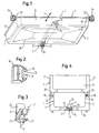
- the drawer 1 shown in Fig. 1 is in the form of an upwardly open pan and has on the upper, open side box edges 2, the respective opposite box sides 3 z. B. project on both sides of the direction indicated by an arrow 4 sliding direction or sliding path, ie projecting from this horizontally.
- the drawer 1 is, for example, within a so-called stander 5 below arranged a baking tube 6 and serves for the storage of dishes such as pans, Gargutlinin and the like.
- the drawer 1 is provided in the middle of the box at the rear end, opposite the handle-equipped front 8 with a guide element 7 according to FIG.
- the guide rail 11 has the profile of a horizontal C, ie it has adjacent to a U-shape facing boundary flanges 13, and a slide 14 for double sliding parts 15 of the guide member 7, which are rounded to minimize frictional forces, as in Fig. 1st and 3 indicated.
- the central guide member 7 also has on both sides of the sliding parts 15 free-projecting projections 21 below the Begrenzungsflansche 13 of the guide rail 11, through which an undesirable lifting movement of the drawer 1 is prevented.
- the guide element 7 has an L-shaped element body whose horizontal limb supports the lower side of the drawer 1 and whose vertical limb 22 (FIGS. 3, 4) bears against the rear side of the box 3.
- FIG. 1 and 4 it can be seen that further guide elements 16 are arranged for the linear guide of the drawer 1 at the top and front 8 and fixedly secured to opposite, in the sliding direction (arrow 4) extending side walls 17 of the stander 5.
- This in Fig. 2 shown as a detail guide elements 16 are fixed to opposite side walls 17 of the housing of the stander 5 and each have a U-shaped sliding bearing 18 (Fig. 2), formed by a lower support 19 for the vertical, front-side support of the drawer 1 and by an upper stroke limiter 20, which engage around the free-standing box edges 2 as free legs of the U-shape (FIGS. 1, 4).
- the guide elements 7, 16 are formed as plastic parts.
Abstract
Description
Die Erfindung bezieht sich auf eine Schubkastenführung für ein Hausgerät, z. B. für einen Herd mit unterhalb des Backrohrs angeordnetem Schubkasten, welcher wannenartig ausgebildeter Schubkasten in Führungselementen schubladenartig verschiebbar gelagert ist, von denen ein Führungselement in der Kastenmitte in einer sich über den gesamten Schiebeweg erstreckenden Führungsschiene und an gegenüberliegenden Kastenseiten mit Führungselementen punktuell und frontseitig an diesen Kastenseiten gelagert bzw. geführt ist.The invention relates to a drawer guide for a household appliance, z. B. for a stove with arranged below the stovepipe drawer, which tray-like drawer is mounted in a drawer slide elements, of which a guide element in the middle of the box in a over the entire sliding path extending guide rail and on opposite sides of the box with guide elements selectively and front to this Box sides stored or guided.
Bei einer bekannten Schubkastenführung sind drei aus Kunststoffmaterial bestehende Führungselemente für den wannenartig ausgebildeten Schubkasten vorhanden, von denen ein Führungselement in einer mittigen Schiene unterhalb des Schubkastens angeordnet ist und zwei Führungselemente sich beidseitig und im frontseitigen Bodenbereich des Schubkastens befinden und dem Schubkasten als vertikale Abstützungen dienen, jedoch eine unerwünschte Hubbewegung des Schubkastens, z. B. bei hoher rückseitiger Beladung nicht verhindern.In a known drawer slide three existing plastic material guide elements for the trough-like drawer are present, of which a guide element is arranged in a central rail below the drawer and two guide elements are located on both sides and in the front floor area of the drawer and the drawer as vertical supports, However, an undesirable lifting movement of the drawer, z. B. at high back loading not prevent.
Der Erfindung liegt die Aufgabe zugrunde, eine Schubkastenführung so auszugestalten, dass einerseits die zur schubladenartigen Geradführung des Schubkastens benötigten Bauteile minimiert sind und andererseits eine sichere Führung des Schubkastens in horizontaler wie in vertikaler Richtung gewährleistet ist.The invention has for its object to design a drawer guide so that on the one hand the required drawer-like linear guide of the drawer components are minimized and on the other hand a secure guidance of the drawer is ensured in both horizontal and vertical direction.
Diese Aufgabe wird bei einer eingangs genannten Schubkastenführung dadurch gelöst, dass in den, an den Kastenseiten angeordneten ortsfesten Führungselementen die an der Oberseite des Schubkastens in Schieberichtung von den gegenüberliegenden Kastenseiten abstehenden Kastenränder geführt sind.This object is achieved in a drawer guide mentioned above in that, in the arranged on the box sides stationary guide elements which are guided at the top of the drawer in the sliding direction of the opposite sides of the box box edges.
Durch die Positionierung der frontseitigen Führungselemente an den Stellen des Schubkastens, an welchen horizontal wie vertikal wirksame Führungsorgane in Form der horizontalen und die Kastenseiten überragenden freien Kastenränder vorhanden sein können, nämlich an der oberen, offenen Seite des Schubkastens wird eine in alle Richtungen wirksame Geradführung des Schubkastens erreicht, die auch bei extrem einseitiger Beladung und bei nicht bestimmungsgemäßer, vorschriftsmäßiger Handhabung durch den Benutzer, z. B. bei Zug nach oben, nicht beeinträchtigt wird.By positioning the front guide elements at the points of the drawer, which horizontally and vertically effective guide members in the form of the horizontal and the box sides superior free box edges can be present, namely at the top, open side of the drawer is effective in all directions straight line of Drawer achieved, even with extremely one-sided loading and improper use, proper handling by the user, eg. B. in train up, is not affected.
In einfacher Weise wird eine wirksame Geradführung des Schubkastens dadurch erreicht, dass gemäß einer bevorzugten Ausführungsform der Erfindung die ortsfesten Führungselemente die jeweiligen Kastenränder nach unten hin als Schiebelager und nach oben hin als Hubbegrenzung umgreifen und dass die Schiebelager und die Hubbegrenzungen als freie Schenkel eines U-förmigen Schiebelagers ausgebildet sind.In a simple manner, an effective linear guidance of the drawer is achieved in that according to a preferred embodiment of the invention, the stationary guide elements surround the respective box edges downwards as a sliding bearing and upwards as a stroke limiter and that the sliding bearing and the stroke limits as free legs of a U- are formed shaped sliding bearing.
Die bodenseitige Führung des Schubkastens in der zentralen Führungsschiene wird dadurch optimiert, dass das in der Kastenmitte am hinteren Ende des Schubkastens befestigte Führungselement mit wenigstens einem im Wesentlichen mittigen, vorzugsweise verrundeten Gleitteil auf der Gleitbahn der Führungsschiene gelagert ist und mit vorzugsweise beidseitig vom Gleitteil abstehenden Ansätzen hubbegrenzend unterhalb von Begrenzungsflanschen der ortsfesten Führungsschiene geführt ist. Dadurch wird in gleicher Weise eine reibungsarme Gleitführung und eine sichere Hubbegrenzung des Schubkastens im mittleren Schubkastenbereich erreicht.The bottom-side guide of the drawer in the central guide rail is optimized in that mounted in the middle of the box at the rear end of the drawer guide element is mounted with at least one substantially central, preferably rounded slide on the slide of the guide rail and with preferably protruding from both sides of the slide approaches Hubbegrenzend is guided below boundary flanges of the stationary guide rail. As a result, a low-friction sliding and a safe stroke limitation of the drawer in the middle drawer area is achieved in the same way.
Die Erfindung ist anhand eines in der Zeichnung dargestellten Ausführungsbeispieles nachstehend erläutert.The invention is explained below with reference to an embodiment shown in the drawing.
Es zeigt:
- Fig. 1
- die perspektivische Darstellung des Schubkastens mit angedeuteten Führungselementen/Führungsschiene,
- Fig. 2 u. 3
- die in Fig. 1 dargestellten Führungselemente als Einzelheit in perspektivischer Darstellung,
- Fig.4
- die schematische Darstellung eines Teils eines Hausgerätes mit einem Schubkasten.
- Fig. 1
- the perspective view of the drawer with indicated guide elements / guide rail,
- Fig. 2 u. 3
- the guide elements shown in Fig. 1 as a detail in perspective view,
- Figure 4
- the schematic representation of a part of a household appliance with a drawer.
Der in Fig. 1 gezeigte Schubkasten 1 ist in Form einer nach oben offenen Wanne ausgebildet und besitzt an der oberen, offenen Seite Kastenränder 2, die jeweils gegenüberliegende Kastenseiten 3 z. B. beidseitig der durch einen Pfeil 4 angedeuteten Schieberichtung bzw. Schiebeweg überragen, d. h. von diesen horizontal abstehen. Der Schubkasten 1 ist beispielsweise innerhalb eines so genannten Standherdes 5 unterhalb eines Backrohres 6 angeordnet und dient der Lagerung von Geschirrteilen wie Pfannen, Gargutträgern und dergleichen. Wie in Fig. 1 und 4 gezeigt, ist der Schubkasten 1 in der Kastenmitte am hinteren Ende, entgegen der mit einem Handgriff ausgestatteten Frontseite 8 mit einem Führungselement 7 gemäß Fig. 3 versehen, d. h. mit ihm verbunden, welches Führungselement 7 mit einem L-förmigen Elementekörper 9 die hintere Kastenkante 10 des Schubkastens 1 umgreift und ihn nach unten hin abstützt. Dieses Führungselement 7 ist allseitig abstützend geführt in einer ortsfesten Führungsschiene 11, die in der Mitte der Führungsbahn des Schubkastens 1 und in Schieberichtung 4 ortsfest am Hausgerät z. B. am Boden 12 des Standherdes 5 befestigt ist. Die Führungsschiene 11 besitzt das Profil eines liegenden C, d. h. sie besitzt im Anschluss an eine U-Form einander zugewandte Begrenzungsflansche 13, sowie eine Gleitbahn 14 für doppelte Gleitteile 15 des Führungselementes 7, die zur Minimierung von Reibungskräften verrundet sind, wie in Fig. 1 und 3 angedeutet. Das mittige Führungselement 7 besitzt ferner beidseitig der Gleitteile 15 freiragend abstehende Ansätze 21 unterhalb der Begrenzungsflansche 13 der Führungsschiene 11, durch welche eine unerwünschte Hubbewegung des Schubkastens 1 verhindert wird. Das Führungselement 7 besitzt schließlich einen L-förmigen Elementekörper, dessen horizontaler Schenkel die Unterseite des Schubkastens 1 abstützt und dessen vertikaler Schenkel 22 (Fig. 3, 4) an der hinteren Kastenseite 3 anliegt.The
Aus Fig. 1 und 4 ist zu entnehmen, dass weitere Führungselemente 16 für die Geradführung des Schubkastens 1 an dessen Oberseite und Frontseite 8 angeordnet sind und zwar ortsfest befestigt an gegenüberliegenden, in Schieberichtung (Pfeil 4) verlaufenden Seitenwänden 17 des Standherdes 5. Diese in Fig. 2 als Einzelheit dargestellte Führungselemente 16 sind befestigt an gegenüberliegenden Seitenwänden 17 des Gehäuses des Standherdes 5 und besitzen jeweils ein U-förmiges Schiebelager 18 (Fig. 2), gebildet durch ein unteres Auflager 19 für die vertikale, frontseitige Abstützung des Schubkastens 1 und durch eine obere Hubbegrenzung 20, welche als freie Schenkel der U-Form die freiragenden Kastenränder 2 umgreifen (Fig. 1, 4). Auf diese Weise wird ein unerwünschtes Anheben des Schubkastens 1 z. B. infolge extrem einseitiger Beladung verhindert. Beim Ausführungsbeispiel sind die Führungselemente 7, 16 als Kunststoffteile ausgebildet.From Fig. 1 and 4 it can be seen that
Claims (6)
Applications Claiming Priority (1)
| Application Number | Priority Date | Filing Date | Title |
|---|---|---|---|
| DE102005044344A DE102005044344A1 (en) | 2005-09-16 | 2005-09-16 | Drawer runner |
Publications (2)
| Publication Number | Publication Date |
|---|---|
| EP1764012A1 true EP1764012A1 (en) | 2007-03-21 |
| EP1764012B1 EP1764012B1 (en) | 2010-03-10 |
Family
ID=37435795
Family Applications (1)
| Application Number | Title | Priority Date | Filing Date |
|---|---|---|---|
| EP06120564A Active EP1764012B1 (en) | 2005-09-16 | 2006-09-13 | Drawer guide |
Country Status (3)
| Country | Link |
|---|---|
| EP (1) | EP1764012B1 (en) |
| AT (1) | ATE460097T1 (en) |
| DE (2) | DE102005044344A1 (en) |
Cited By (4)
| Publication number | Priority date | Publication date | Assignee | Title |
|---|---|---|---|---|
| WO2012048352A1 (en) * | 2010-10-15 | 2012-04-19 | Julius Blum Gmbh | Positioning device for positioning a pushing-out device for pushing out a movably mounted furniture part |
| EP2505101A3 (en) * | 2011-03-30 | 2012-12-26 | Grass GmbH | Guide device for guiding a furniture pull-out that moves relative to an item of furniture |
| US11457737B1 (en) | 2021-03-10 | 2022-10-04 | Haler US Appliance Solutions, Inc. | Drawer glide for oven bottom drawer |
| US11684156B1 (en) * | 2022-02-09 | 2023-06-27 | Haier Us Appliance Solutions, Inc. | Modular drawer guides for sliding drawers |
Citations (3)
| Publication number | Priority date | Publication date | Assignee | Title |
|---|---|---|---|---|
| GB697802A (en) | 1950-11-06 | 1953-09-30 | North Eastern Science Supplies | Improvements in and relating to oven safety appliances |
| US3980365A (en) | 1975-04-04 | 1976-09-14 | P. X. Industries, Inc. | Drawer rail system |
| US5275483A (en) | 1992-08-10 | 1994-01-04 | Frank Rasmussen | Center bottom mounted drawer slide |
-
2005
- 2005-09-16 DE DE102005044344A patent/DE102005044344A1/en not_active Withdrawn
-
2006
- 2006-09-13 AT AT06120564T patent/ATE460097T1/en active
- 2006-09-13 DE DE502006006378T patent/DE502006006378D1/en active Active
- 2006-09-13 EP EP06120564A patent/EP1764012B1/en active Active
Patent Citations (3)
| Publication number | Priority date | Publication date | Assignee | Title |
|---|---|---|---|---|
| GB697802A (en) | 1950-11-06 | 1953-09-30 | North Eastern Science Supplies | Improvements in and relating to oven safety appliances |
| US3980365A (en) | 1975-04-04 | 1976-09-14 | P. X. Industries, Inc. | Drawer rail system |
| US5275483A (en) | 1992-08-10 | 1994-01-04 | Frank Rasmussen | Center bottom mounted drawer slide |
Cited By (7)
| Publication number | Priority date | Publication date | Assignee | Title |
|---|---|---|---|---|
| WO2012048352A1 (en) * | 2010-10-15 | 2012-04-19 | Julius Blum Gmbh | Positioning device for positioning a pushing-out device for pushing out a movably mounted furniture part |
| CN103347419A (en) * | 2010-10-15 | 2013-10-09 | 尤利乌斯·布卢姆有限公司 | Positioning device for positioning a pushing-out device for pushing out a movably mounted furniture part |
| JP2013539691A (en) * | 2010-10-15 | 2013-10-28 | ユリウス ブルム ゲー エム ベー ハー | Positioning device for positioning of a discharge device for discharging movable furniture parts |
| CN103347419B (en) * | 2010-10-15 | 2016-01-27 | 尤利乌斯·布卢姆有限公司 | Be used for the positioner that the ejecting device for being released by the furniture parts supported movingly is positioned |
| EP2505101A3 (en) * | 2011-03-30 | 2012-12-26 | Grass GmbH | Guide device for guiding a furniture pull-out that moves relative to an item of furniture |
| US11457737B1 (en) | 2021-03-10 | 2022-10-04 | Haler US Appliance Solutions, Inc. | Drawer glide for oven bottom drawer |
| US11684156B1 (en) * | 2022-02-09 | 2023-06-27 | Haier Us Appliance Solutions, Inc. | Modular drawer guides for sliding drawers |
Also Published As
| Publication number | Publication date |
|---|---|
| EP1764012B1 (en) | 2010-03-10 |
| DE102005044344A1 (en) | 2007-04-05 |
| DE502006006378D1 (en) | 2010-04-22 |
| ATE460097T1 (en) | 2010-03-15 |
Similar Documents
| Publication | Publication Date | Title |
|---|---|---|
| EP1840473B1 (en) | Domestic appliance with a telescopic device which is attached to a supporting frame | |
| DE202007019575U1 (en) | The refrigerator | |
| DE10216769A1 (en) | Method for supporting shelf in domestic refrigerator or freezer has support elements slideably attached to vertical rails on sides of appliance | |
| DE102013102846B4 (en) | Pull-out runner, household appliance and furniture with a pull-out runner and retrofit kit | |
| EP2843316B1 (en) | Suspension device for an apparatus, in particular a baking oven | |
| EP1306622A1 (en) | Track system for food support in a baking oven | |
| EP1764012A1 (en) | Drawer guide | |
| DE2846764A1 (en) | EXTENDING GUIDE FOR DRAWERS OR DGL. | |
| DE102009002220A1 (en) | Household appliance i.e. cooking device, has useable space lockable by door, net load carrier extractable from useable space, and bearing rollers dismantled and/or mounted from/into inner side of useable space | |
| DE102019107389A1 (en) | Sliding swivel mechanism for a shelf of a piece of furniture or household appliance and furniture or household appliance | |
| DE3544446C1 (en) | Cooling device, in particular domestic refrigerator | |
| DE10102589B4 (en) | Pull-out system for household appliances, in particular stoves | |
| DE102008041525A1 (en) | Tray for holding food for cooking in an oven has a trough shape, with structured edges to slide in the oven guide rails with raised sections and limit stops to prevent accidental falling | |
| AT520691B1 (en) | Guidance system | |
| DE3730342C2 (en) | ||
| DE10162925A1 (en) | A method for sliding a baking tray in and out of an oven has side mounted guide rails and spools on the underside of the tray running on them. | |
| EP1319352B1 (en) | Lowermost drawer for a furniture | |
| DE102019217365A1 (en) | Food receptacle for a household refrigerator with coupling rail for coupling with different guide devices, as well as arrangement, system and household refrigerator | |
| DE3308032C2 (en) | ||
| DE102009020971A1 (en) | Cabinet furnishing | |
| DE102006027703A1 (en) | Domestic oven with a horizontally sliding door has extending baking tray carriers mounted on the rear of the door to facilitate loading of the food items | |
| DE102011088091A1 (en) | Device for holding e.g. baking trays in cooking space of baking oven, has module guide limited by upper guide element and lower guide element, which comprise abrupt vertical offset forming S-shaped bend as integrated pullout stop element | |
| DE3613656C1 (en) | Lath grid | |
| DE102007029519A1 (en) | Wedge plate for furniture i.e. couch furniture, has toothed rail with pair of channels arranged in ends guided on top of each other, where channels serve for guiding lever during forward movement and rearward movement | |
| DE102015206597A1 (en) | Adapter rail for coupling a food support with a running rail of a rail extraction device and arrangement with such an adapter rail |
Legal Events
| Date | Code | Title | Description |
|---|---|---|---|
| PUAI | Public reference made under article 153(3) epc to a published international application that has entered the european phase |
Free format text: ORIGINAL CODE: 0009012 |
|
| AK | Designated contracting states |
Kind code of ref document: A1 Designated state(s): AT BE BG CH CY CZ DE DK EE ES FI FR GB GR HU IE IS IT LI LT LU LV MC NL PL PT RO SE SI SK TR |
|
| AX | Request for extension of the european patent |
Extension state: AL BA HR MK YU |
|
| 17P | Request for examination filed |
Effective date: 20070921 |
|
| 17Q | First examination report despatched |
Effective date: 20071102 |
|
| AKX | Designation fees paid |
Designated state(s): AT BE BG CH CY CZ DE DK EE ES FI FR GB GR HU IE IS IT LI LT LU LV MC NL PL PT RO SE SI SK TR |
|
| GRAP | Despatch of communication of intention to grant a patent |
Free format text: ORIGINAL CODE: EPIDOSNIGR1 |
|
| GRAJ | Information related to disapproval of communication of intention to grant by the applicant or resumption of examination proceedings by the epo deleted |
Free format text: ORIGINAL CODE: EPIDOSDIGR1 |
|
| GRAP | Despatch of communication of intention to grant a patent |
Free format text: ORIGINAL CODE: EPIDOSNIGR1 |
|
| GRAS | Grant fee paid |
Free format text: ORIGINAL CODE: EPIDOSNIGR3 |
|
| GRAA | (expected) grant |
Free format text: ORIGINAL CODE: 0009210 |
|
| AK | Designated contracting states |
Kind code of ref document: B1 Designated state(s): AT BE BG CH CY CZ DE DK EE ES FI FR GB GR HU IE IS IT LI LT LU LV MC NL PL PT RO SE SI SK TR |
|
| REG | Reference to a national code |
Ref country code: GB Ref legal event code: FG4D Free format text: NOT ENGLISH |
|
| REG | Reference to a national code |
Ref country code: CH Ref legal event code: EP |
|
| REG | Reference to a national code |
Ref country code: IE Ref legal event code: FG4D |
|
| REF | Corresponds to: |
Ref document number: 502006006378 Country of ref document: DE Date of ref document: 20100422 Kind code of ref document: P |
|
| REG | Reference to a national code |
Ref country code: SE Ref legal event code: TRGR |
|
| REG | Reference to a national code |
Ref country code: NL Ref legal event code: VDEP Effective date: 20100310 |
|
| PG25 | Lapsed in a contracting state [announced via postgrant information from national office to epo] |
Ref country code: LT Free format text: LAPSE BECAUSE OF FAILURE TO SUBMIT A TRANSLATION OF THE DESCRIPTION OR TO PAY THE FEE WITHIN THE PRESCRIBED TIME-LIMIT Effective date: 20100310 |
|
| LTIE | Lt: invalidation of european patent or patent extension |
Effective date: 20100310 |
|
| PG25 | Lapsed in a contracting state [announced via postgrant information from national office to epo] |
Ref country code: FI Free format text: LAPSE BECAUSE OF FAILURE TO SUBMIT A TRANSLATION OF THE DESCRIPTION OR TO PAY THE FEE WITHIN THE PRESCRIBED TIME-LIMIT Effective date: 20100310 Ref country code: SI Free format text: LAPSE BECAUSE OF FAILURE TO SUBMIT A TRANSLATION OF THE DESCRIPTION OR TO PAY THE FEE WITHIN THE PRESCRIBED TIME-LIMIT Effective date: 20100310 Ref country code: LV Free format text: LAPSE BECAUSE OF FAILURE TO SUBMIT A TRANSLATION OF THE DESCRIPTION OR TO PAY THE FEE WITHIN THE PRESCRIBED TIME-LIMIT Effective date: 20100310 Ref country code: PL Free format text: LAPSE BECAUSE OF FAILURE TO SUBMIT A TRANSLATION OF THE DESCRIPTION OR TO PAY THE FEE WITHIN THE PRESCRIBED TIME-LIMIT Effective date: 20100310 |
|
| REG | Reference to a national code |
Ref country code: IE Ref legal event code: FD4D |
|
| PG25 | Lapsed in a contracting state [announced via postgrant information from national office to epo] |
Ref country code: RO Free format text: LAPSE BECAUSE OF FAILURE TO SUBMIT A TRANSLATION OF THE DESCRIPTION OR TO PAY THE FEE WITHIN THE PRESCRIBED TIME-LIMIT Effective date: 20100310 Ref country code: CY Free format text: LAPSE BECAUSE OF FAILURE TO SUBMIT A TRANSLATION OF THE DESCRIPTION OR TO PAY THE FEE WITHIN THE PRESCRIBED TIME-LIMIT Effective date: 20100310 Ref country code: EE Free format text: LAPSE BECAUSE OF FAILURE TO SUBMIT A TRANSLATION OF THE DESCRIPTION OR TO PAY THE FEE WITHIN THE PRESCRIBED TIME-LIMIT Effective date: 20100310 Ref country code: ES Free format text: LAPSE BECAUSE OF FAILURE TO SUBMIT A TRANSLATION OF THE DESCRIPTION OR TO PAY THE FEE WITHIN THE PRESCRIBED TIME-LIMIT Effective date: 20100621 Ref country code: GR Free format text: LAPSE BECAUSE OF FAILURE TO SUBMIT A TRANSLATION OF THE DESCRIPTION OR TO PAY THE FEE WITHIN THE PRESCRIBED TIME-LIMIT Effective date: 20100611 Ref country code: NL Free format text: LAPSE BECAUSE OF FAILURE TO SUBMIT A TRANSLATION OF THE DESCRIPTION OR TO PAY THE FEE WITHIN THE PRESCRIBED TIME-LIMIT Effective date: 20100310 |
|
| PG25 | Lapsed in a contracting state [announced via postgrant information from national office to epo] |
Ref country code: CZ Free format text: LAPSE BECAUSE OF FAILURE TO SUBMIT A TRANSLATION OF THE DESCRIPTION OR TO PAY THE FEE WITHIN THE PRESCRIBED TIME-LIMIT Effective date: 20100310 Ref country code: BG Free format text: LAPSE BECAUSE OF FAILURE TO SUBMIT A TRANSLATION OF THE DESCRIPTION OR TO PAY THE FEE WITHIN THE PRESCRIBED TIME-LIMIT Effective date: 20100610 Ref country code: IS Free format text: LAPSE BECAUSE OF FAILURE TO SUBMIT A TRANSLATION OF THE DESCRIPTION OR TO PAY THE FEE WITHIN THE PRESCRIBED TIME-LIMIT Effective date: 20100710 Ref country code: SK Free format text: LAPSE BECAUSE OF FAILURE TO SUBMIT A TRANSLATION OF THE DESCRIPTION OR TO PAY THE FEE WITHIN THE PRESCRIBED TIME-LIMIT Effective date: 20100310 |
|
| PLBE | No opposition filed within time limit |
Free format text: ORIGINAL CODE: 0009261 |
|
| STAA | Information on the status of an ep patent application or granted ep patent |
Free format text: STATUS: NO OPPOSITION FILED WITHIN TIME LIMIT |
|
| PG25 | Lapsed in a contracting state [announced via postgrant information from national office to epo] |
Ref country code: DK Free format text: LAPSE BECAUSE OF FAILURE TO SUBMIT A TRANSLATION OF THE DESCRIPTION OR TO PAY THE FEE WITHIN THE PRESCRIBED TIME-LIMIT Effective date: 20100310 Ref country code: PT Free format text: LAPSE BECAUSE OF FAILURE TO SUBMIT A TRANSLATION OF THE DESCRIPTION OR TO PAY THE FEE WITHIN THE PRESCRIBED TIME-LIMIT Effective date: 20100712 Ref country code: IE Free format text: LAPSE BECAUSE OF FAILURE TO SUBMIT A TRANSLATION OF THE DESCRIPTION OR TO PAY THE FEE WITHIN THE PRESCRIBED TIME-LIMIT Effective date: 20100310 |
|
| 26N | No opposition filed |
Effective date: 20101213 |
|
| BERE | Be: lapsed |
Owner name: BSH BOSCH UND SIEMENS HAUSGERATE G.M.B.H. Effective date: 20100930 |
|
| PG25 | Lapsed in a contracting state [announced via postgrant information from national office to epo] |
Ref country code: MC Free format text: LAPSE BECAUSE OF NON-PAYMENT OF DUE FEES Effective date: 20100930 |
|
| REG | Reference to a national code |
Ref country code: CH Ref legal event code: PL |
|
| GBPC | Gb: european patent ceased through non-payment of renewal fee |
Effective date: 20100913 |
|
| PG25 | Lapsed in a contracting state [announced via postgrant information from national office to epo] |
Ref country code: CH Free format text: LAPSE BECAUSE OF NON-PAYMENT OF DUE FEES Effective date: 20100930 Ref country code: BE Free format text: LAPSE BECAUSE OF NON-PAYMENT OF DUE FEES Effective date: 20100930 Ref country code: LI Free format text: LAPSE BECAUSE OF NON-PAYMENT OF DUE FEES Effective date: 20100930 |
|
| PG25 | Lapsed in a contracting state [announced via postgrant information from national office to epo] |
Ref country code: GB Free format text: LAPSE BECAUSE OF NON-PAYMENT OF DUE FEES Effective date: 20100913 |
|
| PG25 | Lapsed in a contracting state [announced via postgrant information from national office to epo] |
Ref country code: LU Free format text: LAPSE BECAUSE OF NON-PAYMENT OF DUE FEES Effective date: 20100913 Ref country code: HU Free format text: LAPSE BECAUSE OF FAILURE TO SUBMIT A TRANSLATION OF THE DESCRIPTION OR TO PAY THE FEE WITHIN THE PRESCRIBED TIME-LIMIT Effective date: 20100911 |
|
| REG | Reference to a national code |
Ref country code: AT Ref legal event code: MM01 Ref document number: 460097 Country of ref document: AT Kind code of ref document: T Effective date: 20110913 |
|
| PG25 | Lapsed in a contracting state [announced via postgrant information from national office to epo] |
Ref country code: AT Free format text: LAPSE BECAUSE OF NON-PAYMENT OF DUE FEES Effective date: 20110913 |
|
| REG | Reference to a national code |
Ref country code: DE Ref legal event code: R081 Ref document number: 502006006378 Country of ref document: DE Owner name: BSH HAUSGERAETE GMBH, DE Free format text: FORMER OWNER: BSH BOSCH UND SIEMENS HAUSGERAETE GMBH, 81739 MUENCHEN, DE Effective date: 20150407 |
|
| REG | Reference to a national code |
Ref country code: FR Ref legal event code: PLFP Year of fee payment: 10 |
|
| REG | Reference to a national code |
Ref country code: FR Ref legal event code: CD Owner name: BSH HAUSGERATE GMBH Effective date: 20151022 |
|
| REG | Reference to a national code |
Ref country code: FR Ref legal event code: PLFP Year of fee payment: 11 |
|
| REG | Reference to a national code |
Ref country code: DE Ref legal event code: R079 Ref document number: 502006006378 Country of ref document: DE Free format text: PREVIOUS MAIN CLASS: A47B0088040000 Ipc: A47B0088400000 |
|
| REG | Reference to a national code |
Ref country code: FR Ref legal event code: PLFP Year of fee payment: 12 |
|
| REG | Reference to a national code |
Ref country code: FR Ref legal event code: PLFP Year of fee payment: 13 |
|
| PGFP | Annual fee paid to national office [announced via postgrant information from national office to epo] |
Ref country code: IT Payment date: 20190920 Year of fee payment: 14 |
|
| PGFP | Annual fee paid to national office [announced via postgrant information from national office to epo] |
Ref country code: DE Payment date: 20190930 Year of fee payment: 14 |
|
| REG | Reference to a national code |
Ref country code: DE Ref legal event code: R119 Ref document number: 502006006378 Country of ref document: DE |
|
| PG25 | Lapsed in a contracting state [announced via postgrant information from national office to epo] |
Ref country code: DE Free format text: LAPSE BECAUSE OF NON-PAYMENT OF DUE FEES Effective date: 20210401 |
|
| PG25 | Lapsed in a contracting state [announced via postgrant information from national office to epo] |
Ref country code: IT Free format text: LAPSE BECAUSE OF NON-PAYMENT OF DUE FEES Effective date: 20200913 |
|
| PGFP | Annual fee paid to national office [announced via postgrant information from national office to epo] |
Ref country code: TR Payment date: 20220912 Year of fee payment: 17 Ref country code: SE Payment date: 20220922 Year of fee payment: 17 |
|
| PGFP | Annual fee paid to national office [announced via postgrant information from national office to epo] |
Ref country code: FR Payment date: 20220920 Year of fee payment: 17 |