EP1763164B1 - Receiver, frequency deviation measuring unit and positioning and ranging system - Google Patents
Receiver, frequency deviation measuring unit and positioning and ranging system Download PDFInfo
- Publication number
- EP1763164B1 EP1763164B1 EP20060003310 EP06003310A EP1763164B1 EP 1763164 B1 EP1763164 B1 EP 1763164B1 EP 20060003310 EP20060003310 EP 20060003310 EP 06003310 A EP06003310 A EP 06003310A EP 1763164 B1 EP1763164 B1 EP 1763164B1
- Authority
- EP
- European Patent Office
- Prior art keywords
- signal
- positioning
- time difference
- clock
- transmission signal
- Prior art date
- Legal status (The legal status is an assumption and is not a legal conclusion. Google has not performed a legal analysis and makes no representation as to the accuracy of the status listed.)
- Expired - Fee Related
Links
Images


Classifications
-
- H—ELECTRICITY
- H04—ELECTRIC COMMUNICATION TECHNIQUE
- H04B—TRANSMISSION
- H04B17/00—Monitoring; Testing
-
- G—PHYSICS
- G01—MEASURING; TESTING
- G01S—RADIO DIRECTION-FINDING; RADIO NAVIGATION; DETERMINING DISTANCE OR VELOCITY BY USE OF RADIO WAVES; LOCATING OR PRESENCE-DETECTING BY USE OF THE REFLECTION OR RERADIATION OF RADIO WAVES; ANALOGOUS ARRANGEMENTS USING OTHER WAVES
- G01S5/00—Position-fixing by co-ordinating two or more direction or position line determinations; Position-fixing by co-ordinating two or more distance determinations
- G01S5/02—Position-fixing by co-ordinating two or more direction or position line determinations; Position-fixing by co-ordinating two or more distance determinations using radio waves
- G01S5/06—Position of source determined by co-ordinating a plurality of position lines defined by path-difference measurements
-
- H—ELECTRICITY
- H04—ELECTRIC COMMUNICATION TECHNIQUE
- H04J—MULTIPLEX COMMUNICATION
- H04J3/00—Time-division multiplex systems
- H04J3/02—Details
- H04J3/06—Synchronising arrangements
- H04J3/0635—Clock or time synchronisation in a network
- H04J3/0682—Clock or time synchronisation in a network by delay compensation, e.g. by compensation of propagation delay or variations thereof, by ranging
Definitions
- the present invention relates to a receiver and a frequency deviation measuring unit which are suitable for measuring the position of a terminal node having radio communication capabilities, and a positioning and ranging system which employs the receiver and frequency deviation measuring unit.
- nodes To implement a sensor net, nodes must be installed in a region under monitoring to continuously sense the state in the region for a long time. For this purpose, the node is required to be small in size and to consume least possible power. Also, since a large number of nodes are distributed, the management of the nodes is a critical aspect.
- UWB communication which is an UWB-IR (Ultra Wide Band - Impulse Radio) communication system that modulates Gaussian mono-pulses in accordance with a PPM (Pulse Position Modulation) scheme.
- PPM Pulse Position Modulation
- a method is known to shift a timing at which a template pulse is generated at predetermined intervals to find a correlation (see, for example, JP-A-2004-241927 ).
- JP-A-2004-258009 discloses a ranging/positioning system which utilizes a transmission of packets and associated response procedure between two radios for ranging and positioning.
- JP-A-2004-254076 discloses a positioning system which comprises a receiver for detecting a change in the distance between a transmitter and a receiver based on a timing adjusting amount when a received pulse waveform is correlated to a template waveform to establish the synchronization.
- a signal from a node is received at a plurality of access points to calculate the position of the node, utilizing time differences of arrival (TDOA) among the access points.
- TDOA time differences of arrival
- JP-A-2005-140617 discloses a positioning method, where a plurality of access points measure a reception time difference between a positioning signal from a node and a reference signal from a reference station to position the node based on the reception time differences utilizing the TDOA.
- the positioning/ranging system is required to reduce power consumption, size and cost of component devices. Therefore, the use of a high-speed, accurate, and stable oscillator and a high-speed counter is not preferable for purposes of measuring a time difference with a high accuracy.
- US 2005/0130669 Al discloses a positioning system using radio signal sent from a node. There, upon receiving to a more reference signals, an access point sense to a position calculation server an interval between the restruction timings of a positioning signal, a reception timing of each of the reference signals, and an ID of each reference station which has sent a reference signal.
- the reference station (RS) 110 may also comprise a synchronization trap module (TRPM) and a time difference measurement module (TDMM), like the access point (AP) 120. Also, the access point (AP) 120 may also have a transmission function similar to that of the reference station (RS) 110.
- TRPM synchronization trap module
- TDMM time difference measurement module
- the positioning server 130 calculates the coordinates of the node 100 from the foregoing information and information recorded in the database 133 contained in the positioning server 130 for positioning and ranging.
- the access point 120 comprises a UWB-IR receiver for receiving intermittent impulse sequences, for example, as shown in Fig. 4 .
- Each of transmitters which are spatially distributed, transmits a pulse sequence, which has been BPSK (Binary Phase Shift Keying) modulated and directly spread.
- the pulse sequence propagates through the space and is received by an antenna 410 of the receiver.
- the signal propagating in the space is, for example, an impulse sequence which has pulses of approximately 2 ns wide transmitted at intervals of approximately 30 ns.
- the impulse used herein has, for example, a primary Gaussian waveform which has been up-converted by a carrier at approximately 4 GHz.
- the receiver comprises the antenna 410, an RF front end unit (RFF) 420, an analog-to-digital conversion module (hereinafter simply called the "A/D conversion module") (ADM) 430, and a baseband module (BBM) 440.
- RPF RF front end unit
- A/D conversion module analog-to-digital conversion module
- BBM baseband module
- the signals separated by the mixers 422 are passed through the low pass filters 425, each of which filters out the carrier at a high frequency of 4 GHz. Consequently, the Gaussian impulse waveforms alone are outputted from the respective low pass filters 425.
- These impulse signals are amplified by the variable gain amplifiers 426, and outputted from the RF front end unit 440 as an I-signal S427i and a Q-signal S427q, respectively.
- the impulse sequence at intervals of approximately 32 MHz requires the synchronization trap and synchronization tracking as described below.
- the sampling timing control unit 570 adjusts the digital conversion timing of the A/D conversion module 430 based on the signals from the synchronization trap module 520 and synchronization tracking module 560.
- the sampling timing control signal S441 is outputted through the sampling timing control unit 570 to delay the digital conversion timing by a short time, for example, approximately 0.5 ns from the normal timing.
- the period (designated by T ck ) of the normal digital conversion is equal to the impulse interval
- the interval of the digital conversion is increased to T ck + T s if the signal S441 is outputted, where T s represents a timing shift time for the digital conversion when the signal S441 is outputted.
- the digital conversion timing is adjusted in response to an output signal S561 from the synchronization tracking module 560.
- the synchronization tracking module 520 detects the advancing timing which is communicated to the sampling timing control unit 570 which responsively outputs a control signal S441 to delay the digital conversion timing by T s from the normal timing.
- the control signal S442 is outputted to advance the digital conversion timing by T s from the normal timing.
- the period of the sampling clock S435 is increased to T ck + T s only in one period, while when the control signal S442 is outputted, the period of the sampling clock S435 is reduced to T ck - T s only in one period.
- Fig. 6 illustrates an exemplary specific configuration of the time difference measurement module 580 for measuring a time difference.
- the time difference measurement module 580 comprises a counter (CNT) 610, a register (REG) 620, a delay unit (D) 630, and a time difference calculation unit (TDCAL) 640.
- the time difference measurement module 580 will be described later in greater detail.
- T RA,a , T RA,b are equal to the distances between the reference station 110 and the access points 120a, 102b divided by the velocity of light.
- T meas,a , T meas,b are values measured by the access points 120a, 120b, respectively, the right side of Equation (2) provides a known value.
- Fig. 8 shows an exemplary structure of the positioning signal S101 transmitted from the node 100, and the reference signal S111 transmitted from the reference station 110.
- the signals S101, S111 are each made up of a preamble 310, a start frame delimiter (hereinafter abbreviated as "SFD") 320, a header 330, and data 340.
- SFD start frame delimiter
- the header or data may include a CRC code or the like for error correction.
- the positioning can be performed simultaneously with a communication. Also, either the node 100 or the reference station 110 need not generate a special signal for the positioning, thus resulting in simplification of the receiver.
- Fig. 11 is a timing chart of a receiver in the access point 120 when it receives the positioning signal S101 and reference signal S111.
- the period of the sampling clock S435 is varied by the sampling timing control signal S441 to trap the synchronization.
- the baseband module 440 starts the demodulation and synchronization tracking are started.
Description
- The present invention relates to a receiver and a frequency deviation measuring unit which are suitable for measuring the position of a terminal node having radio communication capabilities, and a positioning and ranging system which employs the receiver and frequency deviation measuring unit.
- Public attention has been attracted by a wireless sensor network (hereinafter simply called the "sensor net") which includes devices having sensing capabilities installed everywhere around a region to form a network over the air, thereby efficiently capturing information in the real world into an information network such as the Internet. In concept, the sensor net is autonomously built by an infinite number of nodes (terminals), each of which comprises a sensor, a microcomputer, a radio communication device, and a power supply and measures situations relating to persons, objects, environment and the like by the sensor. The sensor net is now under investigation for applications to a variety of fields such as distribution, automobile, agriculture and the like.
- To implement a sensor net, nodes must be installed in a region under monitoring to continuously sense the state in the region for a long time. For this purpose, the node is required to be small in size and to consume least possible power. Also, since a large number of nodes are distributed, the management of the nodes is a critical aspect.
- Likewise, low power radio communication technologies are required for the sensor net. An ultra-wide band (hereinafter abbreviated as "UWB") communication device is expected for use in the sensor net because of its possible low power consumption and small size. The UWB radio communication is defined to employ radiowaves in a bandwidth equal to or larger than 500 MHz with the ratio of the bandwidth to the center frequency of 20 % or more. The UWB communication spreads data over an extremely wide frequency band for transmission and reception, and requires extremely small signal energy per unit frequency band. Accordingly, the UWB communication can communicate without interfering with other communication systems, and can share a frequency band.
- Moe Z. Win et al, "Impulse Radio: How It Works," IEEE Communications Letters, Vol. 2, No. 2, pp.36-38 (February 1998) discloses an example of the UWB communication which is an UWB-IR (Ultra Wide Band - Impulse Radio) communication system that modulates Gaussian mono-pulses in accordance with a PPM (Pulse Position Modulation) scheme. For establishing the synchronization with such a pulse signal, for example, a method is known to shift a timing at which a template pulse is generated at predetermined intervals to find a correlation (see, for example,
JP-A-2004-241927 - Because of its abilities to use pulse signals, the UWB is known to be capable of highly accurate position measurements. For example,
JP-A-2004-258009 JP-A-2004-254076 - Also, in a known node position measuring system, a signal from a node is received at a plurality of access points to calculate the position of the node, utilizing time differences of arrival (TDOA) among the access points. For example,
JP-A-2005-140617 - One of challenges in positioning/ranging systems is improvements in positioning accuracy. The system described in
JP-A-2004-258009 - The system described in
JP-A-2004-254076 - In the system which utilizes TDOA for positioning described in
JP-A-2005-140617 - On the other hand, the positioning/ranging system is required to reduce power consumption, size and cost of component devices. Therefore, the use of a high-speed, accurate, and stable oscillator and a high-speed counter is not preferable for purposes of measuring a time difference with a high accuracy.
-
US 2005/0130669 Al discloses a positioning system using radio signal sent from a node. There, upon receiving to a more reference signals, an access point sense to a position calculation server an interval between the restruction timings of a positioning signal, a reception timing of each of the reference signals, and an ID of each reference station which has sent a reference signal. - The paper "rapid signal acquisition..." by Fujiwara and others, XT-010817163, describes a timing controller for A/D-conversion of two signal streams.
-
WO 97/30360 - It is an object of the present invention to provide a receiver which is reduced in power consumption, size, and cost, and is capable of measuring a time difference with a high accuracy for positioning.
- Among several aspects of the invention disclosed in the present application, a representative one will be described in brief as follows.
- The present invention provides a receiver for receiving a transmission signal from a transmitter.
- The receiver comprises a reception unit for receiving the transmission signal, an A/D conversion module for converting the transmission signal from an analog form to a digital form, a phase shift unit for shifting the phase of a timing at which the A/D conversion module performs the analog-to-digital conversion, and a time difference measurement module for measuring a reception time difference between a first transmission signal and a second transmission signal using the value by which the phase is shifted in the phase shift unit.
- According to the present invention, an accurate time difference can be measured using a low-speed clock, control signal, and counter, so that accurate positioning is achieved by a receiver which is reduced in power consumption, size, and cost, without using a high-speed clock or counter.
- Other objects, features and advantages of the invention will become apparent from the following description of the embodiments of the invention taken in conjunction with the accompanying drawings.
-
-
Fig. 1 is a schematic diagram illustrating the configuration of a positioning system according to a first embodiment of the present invention; -
Fig. 2A is a block diagram illustrating an exemplary configuration of a node (NOD) in the first embodiment; -
Fig. 2B is a block diagram illustrating an exemplary configuration of a reference station (RS) in the first embodiment; -
Fig. 2C is a block diagram illustrating an exemplary configuration of an access point (AP) in the first embodiment; -
Fig. 2D is a block diagram illustrating an exemplary configuration of a positioning server (PS) in the first embodiment; -
Fig. 3 is a sequence diagram showing an outline of transmission and reception of signals in the positioning/ranging system according to the first embodiment; -
Fig. 4 is a circuit block diagram of a receiver according to the first embodiment of the present invention; -
Fig. 5 is a circuit block diagram illustrating the configuration of a baseband module of the receiver, which has a time difference measuring function, according to the first embodiment of the present invention; -
Fig. 6 is a block diagram illustrating the configuration of a time difference measurement module inFig. 5 ; -
Fig. 7 is a diagram for describing the principles of the positioning system according to the present invention; -
Fig. 8 is a schematic diagram showing a positioning signal transmitted from the node and the reference signal transmitted from the reference station according to the present invention; -
Fig. 9 is a diagram for describing a synchronization trapping method according to the present invention; -
Fig. 10 is a diagram for describing a synchronization tracking method according to the present invention; -
Fig. 11 is a diagram for describing a time difference measuring method according to the present invention; -
Fig. 12 is a flow chart illustrating an overall positioning/ranging process according to the first embodiment of the present invention; -
Fig. 13 is a diagram for describing a deviation measuring method according to a second embodiment of the present invention; -
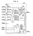
Fig. 14 is a circuit block diagram illustrating the configuration of a baseband module in a receiver, which has a deviation measuring function, according to the second embodiment of the present invention; -
Fig. 15 is a circuit block diagram illustrating the configuration of a frequency deviation measurement module according to the second embodiment of the present invention; -
Fig. 16 is a circuit block diagram illustrating the configuration of a baseband module in a receiver, which has a time difference and deviation measuring function, according to a third embodiment of the present invention; -
Fig. 17 is a circuit block diagram illustrating the configuration of a time difference and deviation measurement module according to the third embodiment of the present invention; -
Fig. 18 is a sequence diagram showing an outline of transmission and reception of signals in the positioning/ranging system according to the third embodiment; -
Fig. 19 is a flow chart illustrating an overall positioning/ranging process according to the third embodiment of the present invention; and -
Fig. 20 is a circuit block diagram illustrating a receiver according to a fourth embodiment of the present invention. - Several embodiments of a receiver and a positioning/ranging system according to the present invention will be described below in detail with reference to the accompanying drawings.
- A receiver according to a first embodiment of the present invention, and a positioning/ranging system using the same will be described with reference to
Figs. 1 to 12 . First, the configuration and operation of the system in the first embodiment will be outlined with reference toFigs. 1 to 3 . -
Fig. 1 illustrates the configuration of the positioning/ranging system according to the first embodiment of the present invention. The positioning/ranging system comprises a plurality of nodes (NOD) 100 (100a, 100b, ...) (which are intended for positioning) each for transmitting a positioning signal; a reference station (RS) 110 for transmitting a reference signal; a plurality of access points (AP) 120 (120a, 120b, 120c) each for receiving the positioning signal and reference signal; a positioning server (PS) 130; and a network (INT) 140 for interconnecting therespective access points 120 andpositioning server 130. It should be noted that the suffixes a, b, c of a reference numeral indicate the same components, and a reference numeral without suffix collectively designates the same components. Also, while either of NOD, RS, AP, and PS has transmission/reception functions, the following description will be centered on the transmission/reception functions required in regard to the embodiments of the present invention for simplicity. - The configuration of the respective components, which make up the system of the present invention, will be outlined by way of example with reference to
Figs. 2A to 2D . -
Fig. 2A is a block diagram illustrating an exemplary configuration of the node (NOD) 100. Each node comprises a signaltransmission control unit 101, asignal generation unit 102, and anantenna 103. Thenode 100 generates a positioning signal S101 in response to an instruction from the signaltransmission control unit 101 based on information from a sensor and a timer contained in or connected to thenode 100, and transmits the positioning signal S101 from theantenna 103. The positioning signal S101 has a waveform uniquely assigned to each node, so that the positioning signal can be identified as to from which node it has been transmitted. -
Fig. 2B is a block diagram illustrating an exemplary configuration of the reference station (RS) 110. Thereference station 110 comprises a baseband module (BBM) 111, an analog-to-digital conversion module (hereinafter simply called the "A/D conversion module") (ADM) 112, an RF front end unit (RFF) 113, a transmission/reception switch (SWT) 115, an antenna (ANT) 117, a signal transmission/reception control unit 118, a transmission signal generator unit 19. TheADM 112 andRFF 113 have anSCG 114 and aCLK 116, respectively, which are sources for generating clock signals to which the synchronization should be established. Thereference station 110 has functions of receiving the positioning signal S101 transmitted from thenode 100, and subsequently transmitting a reference signal S111, having a unique waveform, generated by the transmissionsignal generator unit 119. -
Fig. 2C is a block diagram illustrating an exemplary configuration of the access point (AP) 120. Theaccess point 120 comprises a baseband module (BBM) 121, an analog-to-digital conversion module (ADM) 125, an RF front end unit (RFF) 127, and an antenna (ANT) 129. TheADM 125 andRFF 127 have anSCG 126 andCLK 128, respectively, which are sources for generating clock signals to which the synchronization should be established. Thebaseband module 121 comprises a function of identifying a node or a reference station which has transmitted a signal based on information included in a received signal, which enables thebaseband module 121 to identify the source station. Further, thebaseband module 121 comprises a synchronization trap module (TRPM) 122 for generating a shift signal for varying the phase of the clock signal generated by theSCG 126 to vary the phase of the clock signal for trapping the synchronization of a transmission signal with the clock signal, and a time difference measurement module (TDMM) 123 for measuring a difference between a time at which a positioning signal was received and a time at which a reference signal was received using the clock signal and shift signal. - As indicated by dotted line blocks in
Fig. 2B , the reference station (RS) 110 may also comprise a synchronization trap module (TRPM) and a time difference measurement module (TDMM), like the access point (AP) 120. Also, the access point (AP) 120 may also have a transmission function similar to that of the reference station (RS) 110. -
Fig. 2D is a block diagram illustrating an exemplary configuration of the positioning server (PS) 130. Thepositioning server 130 comprises acommunication unit 131, a positioning/rangingunit 132, andsystem information database 133. Thecommunication unit 131, which functions as an interface for connecting thepositioning server 130 to thenetwork 140, receives a positioning information notification sent from an access point and sends the positioning information notification to the positioning/rangingunit 132. The positioning/rangingunit 132 calculates the position of anode 100 based on information on a signal reception time difference at each access point included in the positioning information notification, as well as information on the positions of the respective access points and reference station, and the like retrieved from thesystem information database 133. -
Fig. 3 is a sequence diagram showing an outline of a signal transmission/reception sequence in the positioning/ranging system of the first embodiment. - The
node 100 transmits a transmission signal including the positioning signal S101 to neighboringreference station 110 andaccess points 120 at an arbitrary time at which thenode 100 desires the calculation of its position, for example, on a periodic basis or at regular intervals, or when a sensor provided in the node detects an abnormal value. Thereference station 110 transmits a transmission signal including the reference signal S111 after receiving the transmission signal including the positioning signal S101. Eachaccess point 120 sends positioning information, for example, a time difference between a time at which the positioning signal was received and a time at which the reference signal was received, ID for identifying the access point, and other information, to thepositioning server 130 through thenetwork 140. - Here, upon receipt of the transmission signal, each
access point 120 performs synchronization trap of the transmission signal, for example, the positioning signal with a sampling clock. After the establishment of the synchronization trap, theaccess point 120 demodulates the transmission signal, and tracks the synchronization. In parallel with the processing involved in the reception of the transmission signal such as the synchronization trap, demodulation, tracking of the synchronization, and the like, eachaccess point 120 measures a difference between the time at which the positioning signal was received and the time at which the reference signal was received, and sends information based on the result of the measurement to thepositioning server 130. - The
positioning server 130 calculates the coordinates of thenode 100 from the foregoing information and information recorded in thedatabase 133 contained in thepositioning server 130 for positioning and ranging. - Referring now to
Figs. 4 to 12 , a description will be given of the specific configuration, operational principles, actions, and advantages of the system according to the first embodiment. - First, the
access point 120 according to the present invention comprises a UWB-IR receiver for receiving intermittent impulse sequences, for example, as shown inFig. 4 . - Each of transmitters, which are spatially distributed, transmits a pulse sequence, which has been BPSK (Binary Phase Shift Keying) modulated and directly spread. The pulse sequence propagates through the space and is received by an
antenna 410 of the receiver. The signal propagating in the space is, for example, an impulse sequence which has pulses of approximately 2 ns wide transmitted at intervals of approximately 30 ns. The impulse used herein has, for example, a primary Gaussian waveform which has been up-converted by a carrier at approximately 4 GHz. - The receiver comprises the
antenna 410, an RF front end unit (RFF) 420, an analog-to-digital conversion module (hereinafter simply called the "A/D conversion module") (ADM) 430, and a baseband module (BBM) 440. - The RF
front end unit 420 comprises a low noise amplifier (LNA) 421, mixers (MIX) 422i, 422q, a π/2 phase shifter (QPS) 423, a clock generator (CLK) 424, low pass filters (LPF) 425i, 425q, and variable gain amplifiers (VGA) 326i, 426q. - It should be noted that suffixes i, q represent an I-signal component (in-phase signal) and a Q-signal component (quadrature signal), respectively, and in the following description, the suffixes i, q are omitted unless they are particularly required.
- A pulse signal (intermittent pulse sequence) received from the
antenna 410 is amplified by thelow noise amplifier 421, and then applied to the mixer 422. The mixer 422 is also applied with a clock signal at approximately 4 GHz generated by theclock generator 424, and as a result, the output of the mixer 422 is separated into a carrier in a 4-GHz band, and an impulse signal having a pulse width of approximately 2 ns in Gaussian waveform. In this event, themixer 422i is directly applied with the output signal of the clock generator 404 and delivers an I-signal which is an in-phase output signal. On the other hand themixer 422q is applied with the clock signal from theclock generator 424 after it has passed through the π/2 phase shifter (QPS) 423 to have the phase delayed by π/2, and therefore delivers a Q-signal which is a quadrature component. - The signals separated by the mixers 422 are passed through the low pass filters 425, each of which filters out the carrier at a high frequency of 4 GHz. Consequently, the Gaussian impulse waveforms alone are outputted from the respective low pass filters 425. These impulse signals are amplified by the variable gain amplifiers 426, and outputted from the RF
front end unit 440 as an I-signal S427i and a Q-signal S427q, respectively. - The A/
D conversion module 430, which comprises A/D converters (ADC) 431, and a sampling clock generator unit (SCG) 433, receives the Gaussian waveform impulse signals of the I-signal S427i and Q-signal S427q which are output signals of the RFfront end unit 420 for conversion into digital signals by the A/D converters 431. The resulting digital signals are outputted from the A/D converters 431. - The input signals S427i, S427q are each divided into a plurality of components which are applied to associated A/D converters 431 within the A/
D conversion module 430 for conversion into digital signals S432. In each A/D converter 431, a sampling timing for converting the input signal S427 into a digital value is controlled by a sampling clock S435. The sampling clock S435 is provided from the samplingclock generator unit 433, and has a period equal to a pulse repeating period of the received impulse sequence. In other words, the input signals S427 are sampled at timings synchronized to the pulses of the impulse sequence. - Generally, however, a transmitter and a receiver are separately installed through the space, and are not synchronized to each other. Therefore, the phase of the received impulse sequence does not match that of the sampling clock. For this reason, the operation called the "synchronization trap" is required for matching the phase of the received impulse sequence with that of the sampling clock.
- Here, a description will be given of two types of clock signals with which the synchronization should be established. A first one is a clock signal at frequency of 4 GHz which is used in the RF front
end unit RFF 420 inFig. 4 . A second one is a clock signal at frequency of approximately 32 MHz which supports the impulse sequences that are transmitted at intervals of approximately 30 ns. - As to a 4-GHz signal component, the received signal is divided into an I-component and a Q-component in the RF front
end unit RFF 420, and the signal is restored in thebaseband module BBM 440. This method permits the signal to be supported without establishing the synchronization in regard to a phase difference. - On the other hand, the impulse sequence at intervals of approximately 32 MHz requires the synchronization trap and synchronization tracking as described below.
-
Fig. 5 illustrates a block diagram of thebaseband module 440. Thebaseband module 440 comprises a matched filter module (MFM) 510, a synchronization trap module (TRPM) 520, a data latch timing control unit (DLTCTL) 530, a data latch module (DLM) 540, a demodulation module (DEMM) 550, a synchronization tracking module (TRCKM) 560, a sampling timing control unit (STCTL) 570, and a time difference measurement module (TDMM) 580. - The matched
filter module 510 detects a matching degree of a plurality of digitized I- and Q-signals S432ia - S432ic and S432qa - S432qc to an expected spread code, and outputs a signal S511 indicative of the result of the measurement. - The
synchronization trap module 520 traps the synchronization of the received signal (impulse sequence) using signals S511ia and S511qa. While synchronization trapping is not established, a signal S522 is outputted to the samplingtiming control unit 570 to gradually change the timing at which the A/D conversion module 430 converts a received signal into a digital signal using sampling timing control signals S441, S442. Upon establishment of synchronization trap, synchronization timing information is communicated to the data latchtiming control unit 530 through a signal S521. - The data latch
timing control unit 530 applies a control signal S531 to thedata latch module 540 at a timing synchronized with the received signal S511, and thedata latch module 540 communicates only data which matches the timing to thedemodulation module 550 andsynchronization tracking module 560 as a signal S541. Thedemodulation module 550 demodulates the data based on the signal selected by thedata latch module 540, and outputs digital data S443. - On the other hand, the
synchronization tracking module 560 detects whether or not the received signal S427 is out of synchronization, based on the signal S541 selected by thedata latch module 540. If out-of-synchronization has occurred, thesynchronization tracking module 560 adjusts a digital conversion timing of the A/D conversion module 430 with sampling timing control signals S441, S442 through the samplingtiming control unit 570. - The sampling
timing control unit 570 adjusts the digital conversion timing of the A/D conversion module 430 based on the signals from thesynchronization trap module 520 andsynchronization tracking module 560. When the signal S522 is outputted from thesynchronization trap module 520, the sampling timing control signal S441 is outputted through the samplingtiming control unit 570 to delay the digital conversion timing by a short time, for example, approximately 0.5 ns from the normal timing. Specifically, while the period (designated by Tck) of the normal digital conversion is equal to the impulse interval, the interval of the digital conversion is increased to Tck + Ts if the signal S441 is outputted, where Ts represents a timing shift time for the digital conversion when the signal S441 is outputted. - Also, the digital conversion timing is adjusted in response to an output signal S561 from the
synchronization tracking module 560. When the digital conversion timing advances with respect to the analog signal S427 inputted to the A/D conversion module 430, thesynchronization tracking module 520 detects the advancing timing which is communicated to the samplingtiming control unit 570 which responsively outputs a control signal S441 to delay the digital conversion timing by Ts from the normal timing. Conversely, when the digital conversion timing is delayed with respect to the analog signal S427, the control signal S442 is outputted to advance the digital conversion timing by Ts from the normal timing. - Specifically, when the control signal S441 is outputted from the sampling
timing control unit 570, the period of the sampling clock S435 is increased to Tck + Ts only in one period, while when the control signal S442 is outputted, the period of the sampling clock S435 is reduced to Tck - Ts only in one period. By thus controlling the period of the sampling clock S435, it is possible to trap and track the synchronization. - The following description is given of the basic operation of the receiver for receiving the pulse signal in the UWB-IR communication. The pulse signal is received by the
antenna 410, and a shaped waveform at a required frequency is extracted by the RFfront end unit 420, and converted into a digital signal by the A/D conversion module 430. Then, thebaseband module 440 processes the digital signal to extract a communication data S433 which is eventually delivered. - A time
difference measurement module 580 is additionally provided for positioning in thebaseband module 440 in the UWB-IR receiver of this embodiment. The timedifference measurement module 580, which realizes accurate measurements with low power consumption, accurately measures a time difference using the functions inherently provided in the receiver and a relatively low-speed counter. -
Fig. 6 illustrates an exemplary specific configuration of the timedifference measurement module 580 for measuring a time difference. The timedifference measurement module 580 comprises a counter (CNT) 610, a register (REG) 620, a delay unit (D) 630, and a time difference calculation unit (TDCAL) 640. The timedifference measurement module 580 will be described later in greater detail. - The mechanism of the positioning system according to this embodiment will be described in greater detail with reference to
Figs. 7 and 8 , giving an example of positioning anode 100a. - Referring first to
Fig. 7 , a description will be given of the principles of the positioning system according to the present invention. - In
Fig. 7 , Tx represents a transmission, and Rx a reception. A positioning signal S101 transmitted by thenode 100a is received by thereference station 110 after a time TNR, and then received by theaccess point 120a after a time TNA,a. Thereference station 110 transmits a reference signal S111 after a time TRP from the reception of the positioning signal S101. The reference signal S111 is received by theaccess point 120a after a time TRA,a from its transmission. Theaccess point 120a measures a time Tmeas,a from the reception of the positioning signal S101 to the reception of the reference signal S111. In this event, the following equation is established:
- Also, the positioning signal S101 and reference signal S111 are received by the
access points 

where TNR represents a time from the transmission of the positioning signal S101 from thenode 100a to the reception of the positioning signal S101 by thereference station 110; TRP represents a time from the reception of the positioning signal S101 by thereference station 110 to the transmission of the reference signal S111 from thereference station 110; TRA,a, TRA,b, TRA,c represent times from the transmission of the reference signal S111 from thereference station 110 to the reception of the reference signal S111 by theaccess points node 100a to the reception of the positioning signal S101 by theaccess points access points - The following equation is derived from Equation (1a) and Equation (1b):

where TRA,a, TRA,b are equal to the distances between thereference station 110 and theaccess points 120a, 102b divided by the velocity of light. Also, since Tmeas,a, Tmeas,b are values measured by theaccess points - Consequently, it is possible to calculate a difference TNA,a - TNA,b between the time at which the positioning signal S101 arrived at the
access point 120a, and the time at which the positioning signal S101 arrived at theaccess point 120b. While there are three access points in this description, the number of the access points is not limited to this particular value. -
Fig. 8 shows an exemplary structure of the positioning signal S101 transmitted from thenode 100, and the reference signal S111 transmitted from thereference station 110. The signals S101, S111 are each made up of apreamble 310, a start frame delimiter (hereinafter abbreviated as "SFD") 320, aheader 330, anddata 340. The header or data may include a CRC code or the like for error correction. - The
preamble 310 is used by an access point which has received the signal S101 or S111 to trap the synchronization. TheSFD 320 comprises a particular bit pattern indicative of the end of the preamble and the start of theheader 330. Theheader 330 contains information such as the identifier of a source and the identifier of a destination of the signal S101, S111, and the like. Thedata 340 contains information from the source of the signal S101, S111. - By using the signals S101, S111 for communication, the positioning can be performed simultaneously with a communication. Also, either the
node 100 or thereference station 110 need not generate a special signal for the positioning, thus resulting in simplification of the receiver. - A transmission timing or a reception timing of the signal S101, S111 is determined to be a timing at which a certain particular portion thereof is transmitted or received. For example, the transmission timing is defined to be a timing at which the
SFD 320 of the signal S101, S111 is transmitted, while the reception timing is defined to be a timing at which it is received. - In this positioning system, the positioning accuracy for the
node 100 under measurement depends on the accuracy of the time difference of arrival TDOA, i.e., the accuracy with which theaccess point 120 measures the time difference Tmeas. The positioning accuracy further depends on measured time errors among a plurality ofaccess points - This embodiment employs a relatively low-speed oscillator and a low-speed counter to accurately measure a time difference to reduce the power consumption and circuit scale.
- Details on such a measurement will be described below with reference to
Figs. 9 to 11 . - Referring first to
Fig. 9 , a synchronization trapping method will be described. When an impulse sequence S427 inputted to the A/D conversion module 430 is not in phase with the sampling clock S435, the digital signal S432 A/D-converted from the impulse sequence S427 has a noise level value. When the impulse sequence S427 is in phase with the sampling clock S435, sampled pulses are outputted to the digital signal S432. - The digital signal S432 is inputted to the
baseband module 440 which determines from the level of the signal S432 whether the impulse sequence S427 is in phase with the sampling clock S435. When they are not in phase, a shift signal (timing shift time = Ts) is generated to adjust the phase. - Specifically, the sampling timing control signal S441 is outputted to increase or reduce the period of the sampling clock signal S435 by a certain time (Ts) to shift the sampling timing. This operation is repeated until the impulse sequence S427 becomes in phase with the sampling clock S435. In this way, the phase of the sampling clock S435 is shifted by the sampling timing control signal S441 to carry out the synchronization trap with the impulse sequence S427.
- The A/D converters 431ia, 431ib, 431ic of the A/
D conversion module 430 are applied with sampling clocks which are delayed, for example, by 0.5 ns from one another. Specifically, when the Gaussian impulse signal has a width of 2 ns, this impulse signal is converted into a digital value at positions shifted by 0.5 ns from one another, and the resultant digital values are outputted from the A/D converters 431ia, 431ib, 431ic. These digital values converted at different positions are used for the synchronization tracking. - Even after the synchronization trap is once established, the impulse sequence becomes gradually out of synchronization with the sampling clock if a frequency deviation is present in clocks used in the transmitter and receiver. In the UWB-IR scheme, the synchronization must be established to an impulse having a short duration of approximately 2 ns. While the synchronization tracking is not needed if the transmitter and receiver employ crystal oscillators, which exhibit high frequency accuracies, for use in generating the clocks, the accurate crystal oscillator is expensive. For aiming at a reduction in cost, a system must be able to receive even using a low-accuracy crystal oscillator. For this purpose, the operation called the synchronization tracking is required.
- This synchronization tracking will be described with reference to
Figs. 10 and11 . - First, in
Fig. 10 , from astate 830 in which a pulse is sampled at a peak thereof, a frequency deviation causes a shift between the peak of the pulse and the sampling timing, as shown instates - The
baseband module 440 detects this shift using digital signals S432 which have been A/D-converted at three points, and adjusts the period of the sampling clock S435 through the control signals S441, S442. Specifically, when the sampling clock S435 advances with respect to the impulse as shown in thestate 810, the period of the sampling clock S435 is extended by a certain time (Ts) by the shift signal. On the other hand, when the sampling clock S435 delays with respect to the impulse as shown in thestate 820, the period of the sampling clock S435 is reduced by the certain time (Ts) by the shift signal. - As described above, the sampling
clock generator unit 433 generates sampling clocks S4335ia - S4335ic, S435qa - S435qc for determining the sampling timing of the A/D converter 431 in response to the sampling timing control signals S441, S442 applied from thebaseband module 440. - The
baseband module 440 performs such signal processing as synchronization trap, synchronization confirmation, signal demodulation, synchronization tracking, and time difference measurement using the received signal S432 converted into digital values, and controls the sampling timing for the A/D conversion module 430. Demodulated data S443 and positioning data S444 are outputted from thebaseband module 440, and transmitted to a higher-level layer which processes the data S443 and S444. - Next, the principles of the time difference measurement will be described with reference to
Fig. 11. Fig. 11 is a timing chart of a receiver in theaccess point 120 when it receives the positioning signal S101 and reference signal S111. Before the establishment of the synchronization trap with the positioning signal S101, the period of the sampling clock S435 is varied by the sampling timing control signal S441 to trap the synchronization. As the positioning signal S101 is received and the synchronization trap is established, thebaseband module 440 starts the demodulation and synchronization tracking are started. - Since frequency deviations are included in the clocks of the transmitter and receiver, the synchronization is gradually lost even after the synchronization has been once established. The
synchronization tracking module 560 detects a shift from the synchronization, and adjusts the period of the sampling clock S435 through the control signals S441, S442. - Upon complete receipt of the
data 340 in the positioning signal S101, the receiver performs the synchronization trap. The receiver performs the demodulation and synchronization tracking after the synchronization trap has been established with the reference signal S111. - The
access point 120 measures the time difference Tmeas from the reception of the positioning signal S101 to the reception of the reference signal S111. Assume herein that the time at which the signal S101, S111 is received is a time at which theSFD 320 has been received. - The sampling clock S435 generally has a period Tck which, however, is increased to Tck+ Ts or reduced to Tck- Ts when the control signal S441 or S442 are outputted, respectively. Making use of these values, the reception time difference Tmeas between the positioning signal S101 and reference signal S111 is given by the following equation:

where Tck represents a normal sampling clock period; Ts, a timing shift time; Nck, the number of counted pulse sampling clocks; and Np, Nm, the numbers of counted sampling timing control signals +Ts, -Ts. - In other words, the reception time difference Tmeas is calculated by counting the numbers of the sampling clocks S435 and its control signals S441, S442.
- This reception time difference Tmeas is calculated by the time difference measurement module (TDMM) 580 (see
Fig. 6 ). Next, the operation of the timedifference measurement module 580 will be described. The timedifference measurement module 580 is applied with a sampling clock S435d, the sampling timing control signals S441, S442, and an SFD detection signal S551. The clock S435d and control signals S441, S442 are inputted tocounters 610a - 610c, respectively, which deliver signals S611a - S611c indicative of their respective count values. - The SFD detection signal S551 is outputted from the
demodulation module 550 at a timing at which theSFD 320 is detected. The count values S611a - S611c are stored inregisters 620a - 620c, respectively, at a timing at which theSDF 320 is detected. Also, the SFD detection signal S551 is delayed by a delay unit 630, and resets the count values of the counters 610. - The time
difference calculation unit 640 calculates the reception time difference Tmeas in accordance with Equation (3) using the values stored in the registers 620. The time difference Tmeas is outputted to a higher-level layer as a signal S444a. The higher-level layer identifies the ID and the like of thenode 100 from demodulated data S443, and transmits necessary information and the reception time difference Tmeas to thepositioning server 130. Thepositioning server 130 calculates the position of thenode 100 based on the data from theaccess point 120. - The reception time difference Tmeas may be calculated by the higher-level layer,
positioning server 130 or the like instead of the timedifference measurement module 580. - Also, the Tmeas measuring start time and end time may not be the time at which the SFD is detected. For example, the measurement may be started from the end of data in the positioning signal S101. In this event, a measuring time is reduced as compared with the example described above, thus making it possible to reduce the number of bits of the counter and consequently reduce the circuit scale.
- Before the synchronization trap is not established, the sampling timing control signal S441 is periodically outputted. This is because a certain time is taken to determine whether or not the synchronization is trapped. Making use of this fact, the number of the sampling clocks S435d in the meantime can be calculated from the number of counted sampling timing control signals S441.
- The foregoing description has been given of a method and circuit for accurately measuring the reception time difference Tmeas with low power consumption. Specifically, the numbers of the sampling clocks S435 and sampling timing control signals S441, S442 are counted, and the reception time difference Tmeas is calculated in accordance with Equation (3).
-
Fig. 12 illustrates a flow chart of an overall positioning/ranging process according to this embodiment. - A
node 100 transmits a transmission signal including a positioning signal S101 to neighboringreference station 110 andaccess points 120 at an arbitrary time at which thenode 100 desires the calculation of the position (S1201). Thereference station 110 transmits a transmission signal including a reference signal S111 after it has received the positioning signal S101 (S1202). Each of thereference station 110 andaccess points 120 sends a transmission signal including, for example, the positioning signal receiving time, the reference signal receiving time, an ID for identifying the access point, and other information to thepositioning server 130 through thenetwork 140. - Here, upon receipt of the transmission signal, for example, the positioning signal S101, each
access point 120 performs the synchronization trap of the positioning signal S101 with the sampling clock. After the establishment of the synchronization trap, theaccess point 120 performs the demodulation and synchronization tracking. In parallel with the processing involved in the reception of the transmission signal such as the synchronization trap, demodulation, tracking of the synchronization, and the like, eachaccess point 120 measures a difference Tmeas between the time at which the positioning signal S101 was received and the time at which the reference signal S111 was received (S1203), and sends information based on the result of the measurement to the positioning server 130 (S1204). Thepositioning server 130 calculates the coordinates of thenode 100 from the foregoing information and information recorded in thedatabase 133 contained in thepositioning server 130 for positioning and ranging (S1205). - In this way, by the use of the system of this embodiment which comprises the functions of synchronization trap, synchronization tracking, reception time difference calculation and the like, the time difference can be accurately measured even with the use of a relatively low-speed clock, control signal, and counter. The operating frequency of the counter is the same as the pulse repeating frequency (1/Tck), for example, approximately 32 MHz. Since the counter operates at a low frequency, the power consumption and circuit scale can be reduced. Further, the designing is facilitated because the SFD detection signal S551 indicative of the start/end of the measurement of Tmeas is in synchronism with the sampling clock.
- This method exhibits a time measuring accuracy of ±Ts (timing shift time). Assuming that Ts is chosen, for example, to be 0.5 ns, the accuracy is the same as that when a measurement is made using a 1-GHz oscillator and counter. Specifically, a positioning accuracy can be improved to approximately 30 cm.
- As described above, the receiver in the access point according to this embodiment can use a low-speed clock, and control signals for shifting the phase of the clock in measuring a reception time difference between the positioning signal and reference signal. Then, the numbers of the clocks and control signals are counted by low-speed counters, respectively, to calculate the reception time difference. The accuracy of the calculated reception time difference is determined by a time by which the phase is shifted by one control signal. It is therefore possible to measure the time difference with a high accuracy. The measurement of the reception time difference using this method eliminates the need for a high-speed clock or a high-seed counter, and reduces the power consumption and circuit scale.
- In the foregoing position detection system, information on the access point may be communicated to the server through a wired or a wireless network. Also, the access point can additionally function as the reference station and positioning server.
- For example, the positioning/ranging system may comprise a first communication device for transmitting a positioning signal, and a second communication device for transmitting a reference signal to the first communication device after the positioning signal has been received, wherein the first communication device may comprise a synchronization trap module for generating a shift signal for varying the phase of a clock signal to perform synchronization trap of the reference signal with the clock signal, and a position calculation unit for measuring a time difference from the transmission of the positioning signal to the reception of the reference signal, and calculating the distance between the first communication device and the second communication device using the time difference.
- According to this embodiment, the time difference can be accurately measured using a low-speed clock, control signal, and counter, thus achieving accurate positioning by a receiver which is reduced in power consumption, size and cost, without using a high-speed clock or counter.
- Next, a frequency deviation measuring unit for measuring and reducing a clock error between access points according to a second embodiment of the present invention will be described with reference to
Figs. 13 to 15 . - In the first embodiment of the present invention described above, the reception time difference Tmeas measured by the
access point 120 includes an error due to the accuracy of the clock frequency. - The
positioning server 130 calculates the position of thenode 100 in accordance with Equation (2) using the reception time differences Tmeas measured by a plurality of access points 120. When a clock error is taken into consideration, the second term on the right side of Equation (2) is:
access points access points - The error (Treal,a·δa + Treal,b·δb) is transformed to:

- (Treal,a - Treal,b) depends on the distance between the
node 100 and theaccess point 120 and the distance between thereference station 110 and theaccess point 120, and has a value of approximately 100 ns at most assuming, for example, a positioning system for an area of 30 meters in every direction. On the other hand, Treal,b depends on a signal processing time in thereference station 110, the data length of the positioning signal S101, the length of the preamble in the reference signal S111, and the like, and has a value of at least 0.6 ms or more assuming, for example, a transmission rate of 250 kbps and the preamble having a length of 20 bytes. In this event, a time error of approximately 13 ns occurs assuming, for example, that a deviation of the clocks between the access points (δa -δb) is 20 ppm. This is converted to approximately 4 meters of error in distance. - Therefore, in the error expressed by Equation (5), the second term is predominant. Stated another way, a main cause of the error is not an absolute deviation of a clock (deviation from a real time) but a relative deviation of clocks between access points. Accordingly, the error is reduced by reducing the relative deviation of the clocks between the access points.
- The frequency deviation measuring unit of this embodiment measures a frequency deviation of clocks in a transmitter and a receiver to reduce a positioning error. Specifically, the frequency deviation measuring unit measures a clock error between access points with reference to the clock frequency of the transmitter to reduce the clock error. The operational principles of the frequency deviation measuring unit will be described below with reference to
Fig. 13 . -
Fig. 13 is a timing chart for the A/D conversion module 430 in theaccess point 120a when it receives the reference signal S111, showing a state after the synchronization has been established with the reference signal S111. In this state, an analog signal S432 inputted to the A/D conversion module 430 is in synchronism with a sampling clock S435. Stated another way, the period of the sampling clock S435 is controlled by the sampling timing control signals S441, S442 to synchronize with the analog signal S432. - Also, since the reference signal S111 is generated by the
reference station 110, the analog signal S432 reflects a frequency deviation of the clock in thereference station 110. Therefore, the period at which the control signal S441 is outputted corresponds to a deviation between the clock in theaccess point 120a and the clock in thereference station 110. This deviation is expressed by:
where δr represents the deviation of the clock in thereference station 110. - Specifically, the deviation (δa -δr) is calculated by counting the sampling clock S435 and sampling timing control signals S441, S442. The deviations of the
respective access points 120 to thereference station 110 are calculated and corrected by the foregoing method to reduce the error caused by the deviation of the clock frequency. - Next, the configuration of the frequency deviation measuring unit will be described with reference to
Figs. 14 and15 . As illustrated inFig. 14 , the deviation measuring unit comprises a frequency deviation measurement module (FDMM) 1110 in abaseband module BBM 440.Fig. 15 illustrates a specific exemplary configuration of the frequencydeviation measurement module 1110. - The frequency
deviation measurement module 1110 comprisescounters 610a - 610c, registers 620d - 620f, and a deviation calculation unit (FDCAL) 1240. The frequencydeviation measurement module 1110 is applied with a sampling clock S435d, sampling timing control signals S441, S442, an SFD detection signal S551, and a data end signal S552, and outputs a measured deviation S444b. The data end signal S552 is outputted from ademodulation module 550 at the time the end ofdata 340 is reached in a received signal. - The clock S435d and control signals S441, S442 are inputted to the
counters 610a - 610c, respectively, which output signals S611a - S611c indicative of their respective count values. The count values S611a - S611c are reset at a SFD detection timing, and stored in theregisters 620d - 620f, respectively, at a timing thedata 340 is over. The frequencydeviation calculation unit 1240 calculates a deviation in accordance with Equation (6) using the values in theregisters 620d - 620f, and outputs the calculated deviation to a higher-level layer. - In the foregoing example, the deviation is corrected using the reference signal S111, but this is not a limitation. Alternatively, the positioning signal S101 from the
node 100, a signal from another transmitter, or the like may be used instead for the correction. Also, the timing at which the deviation is measured is not limited to the timing at which the positioning is performed, but the measurement may be made at an arbitrary time, such as at the time of installation, on a periodic basis, or when the temperature changes, and the like. The data on the deviation is stored in a database in theaccess point 120 orpositioning server 130. If the clock frequency deviation has been previously measured between access points in the foregoing manner, a time difference between access points can be measured using the positioning signal arriving times themselves to detect the position of the node. - In this way, the deviation can be corrected to improve the positioning accuracy by measuring the periods at which the control signals S441, S442 are outputted after the establishment of synchronization trap. In addition, when the deviation can be corrected, a positionable range is expanded. For expanding a positionable range, communications are required over a long communication distance at a low transmission rate. At a low transmission rate, a long preamble causes a long time difference Tmeas to be measured, thus increasing the error resulting from the frequency deviation. By correcting the deviation, this error can be reduced, and the positioning can be made at low transmission rates to expand a positioning range. Also, an inexpensive crystal oscillator with a large frequency deviation can be used, resulting in a reduction in cost.
- Further, the frequency deviation measuring unit of this embodiment can be used not only in a positioning/ranging system but also for the maintenance of components of a transmitter or a receiver which utilizes the result of measuring the frequency deviation.
- Next, a third embodiment of the present invention will be described with reference to
Figs. 16 to 19 . A receiver of this embodiment comprises the function of the frequency deviation measuring unit in the second embodiment added to the receiver of the first embodiment.Fig. 16 is a diagram illustrating the configuration of abaseband module 440 which comprises a time difference measuring function and a deviation measuring function.Fig. 17 is a diagram illustrating an exemplary configuration of a time difference/frequency deviation measurement module (TD&FDMM) 1310. - In
Figs. 16 and17 , the time difference/frequency deviation measurement module (TD&FDMM) 1310 is applied with a sampling clock S435d, sampling timing control signals S441, S442, an SFD detection signal S551, and a data end signal S552, and outputs a measured time difference S444a and deviation S444b. - The time difference/frequency
deviation measurement module 1310 comprisescounters 610a - 610c,registers 620a - 620f,delay units 630a - 630c, a timedifference calculation unit 640, and a frequencydeviation calculation unit 1240. Count values of thecounters 610a - 610c are stored in theregisters 620a - 620c, respectively, in response to the SFD detection signal S551, and then, the count values are reset. Also, the count values are stored in theregisters 620d - 620f, respectively, in response to the data end signal S552. - The time
difference calculation unit 640 calculates a time difference Tmeas in accordance with Equation (3) using the values in theregisters 620a - 620c. The frequencydeviation calculation unit 1240 calculates a deviation of the clock in accordance with Equation (6) using the values in theregisters 620d - 620f. The calculated values are both outputted to a higher-level layer. - The higher-level layer or
positioning server 130 comprises a clock deviation correction unit for correcting an error due to a clock deviation of the reception time difference Tmeas. Thepositioning server 130 calculates the position of thenode 100 using the reception time difference Tmeas measured by eachaccess point 120. -
Fig. 18 is a sequence diagram showing an outline of signal transmission/reception in the positioning/ranging system of this embodiment, andFig. 19 is a flow chart illustrating an overall positioning/ranging process. - The
node 100 transmits a transmission signal including a positioning signal S101 to neighboringreference station 110 andaccess points 120 at an arbitrary time at which thenode 100 desires the calculation of the position (S1901). Thereference station 110 transmits a transmission signal including a reference signal S111 after it has received the positioning signal S101 (S1902). Eachaccess point 120 traps the synchronization of the positioning signal with sampling clock upon receipt of the transmission signal, for example, positioning signal S101. After the synchronization trap is established, theaccess point 120 performs demodulation and synchronization tracking. In parallel with the processing involved in the reception of the transmission signal such as the synchronization trap, demodulation, tracking of the synchronization, and the like, eachaccess point 120 measures a difference Tmeas between the time at which the positioning signal S101 was received and the time at which the reference signal S111 was received in accordance with Equation (3), and also calculates a deviation of the clock in accordance with Equation 6 (S1903). Eachaccess point 120 sends the reception time difference Tmeas and the clock deviation based on the result of these measurements to the server 130 (S1904, S1905). Theserver 130 corrects the reception time difference Tmeas of each access point for the deviation from the information transmitted thereto and information recorded in the database contained therein (S1906), and calculates the coordinates of thenode 100 for positioning and ranging (S1907). - In the foregoing manner, the reception time difference Tmeas and deviation are calculated from the numbers of the counted sampling clock S435d and sampling timing control signals S441, S442. In this way, an accurate time deviation measurement and positioning can be accomplished by a receiver which is reduced in power consumption, size and cost.
- Also, a positioning function can come standard with the receiver. In other words, all nodes having a reception function can serve as positioning access points, thus contributing to the formation of a flexible positioning system.
- As described above, according to the third embodiment, errors can be reduced in time difference measurement, the positioning can be made at a low transmission rate, and a positioning range can be expanded by correcting a clock deviation between access points. Also, an inexpensive crystal oscillator with a large frequency deviation can be used, resulting in a reduction in cost.
- While the description so far made has been centered on a system comprising the
nodes 100,reference station 110,access points 120, andpositioning server 130, as illustrated inFig. 1 , the time difference measuring system and deviation measuring system according to the present invention exert their effects in other systems which differ in configuration as well. - For example, the method according to the present invention is effective for measuring the distance between two communication devices. When a first communication device transmits a positioning signal to a second communication device, and the second communication device, which has received the positioning signal, transmits a response signal to the first communication device, the distance therebetween is calculated by measuring a time from the transmission of the positioning signal from the first communication device to the reception of the response signal by the first communication device. With the use of the receiver according to the present invention, the time difference can be measured from the clock and control signals associated therewith to accurately calculate the distance between the two communication devices.
- The time measured in the foregoing manner includes a processing time in the second communication device, and can therefore cause an error when the distance is calculated if a deviation is present in the clocks of the two communication devices. However, the method according to the present invention reduces the error in the measured distance by measuring and correcting the deviation.
- While the foregoing description has been made on a receiver for use in an access point in connection with an exemplary receiver which converts a received impulse sequence from an analog form to a digital form at a pulse repetition period, the time difference measuring method and deviation measuring method of the present invention are not limited to this receiver.
- For example, a positioning/ranging system according to a fourth embodiment of the present invention effectively employs a receiver having the ability to measure a time difference and a deviation, similar to those in the first to third embodiments, in a communication system which correlates a template waveform with a received signal to trap the synchronization.
-
Fig. 20 illustrates an exemplary configuration of areceiver 200 according to the fourth embodiment of the present invention. Thereceiver 200 comprises a templatewaveform generator unit 202; atiming shift unit 203 for shifting a timing (phase) at which the template waveform is generated; acorrelator 204 for correlating the template waveform with a received signal fed through anantenna 210; an A/D converter 205 for analog-to-digital converting an output signal of thecorrelator 204; asampling clock generator 201 for providing a timing for the A/D conversion; and a pseudo random code generator unit (not shown). Further, a baseband module (BBM) 206, which comprises a synchronization trap/synchronization tracking function 207 and a deviation measurement module (TD&FDMM) 208, traps the synchronization of a received signal with the template waveform and tracks the synchronization, corrects a clock deviation, and measures the position or distance, using a timing shift function. - The template
waveform generator unit 202 generates the template waveform using a pseudo-random code which was used for spreading a signal on the transmission side of the communication system. Thecorrelator 204 correlates the template waveform with a received signal, sends the result of the correlation to the baseband module (BBM) 206 through the A/D converter 205. The synchronization trap/synchronization tracking module 207 detects the time at which the received signal is most correlated with the template waveform, while controlling the timing at which the template waveform is generated. Subsequently, the synchronization trap/synchronization tracking module 207 controls the timing at which the template waveform is generated to maintain the correlation at a high level. - The synchronization trap/synchronization tracking module 207 and time difference/frequency deviation measurement module (TD&FDMM) 208 have functions of synchronization trap for shifting the phase of the template waveform, synchronization tracking, and reception time difference measurement or deviation measurement, as described in the third embodiment. With these functions, the time difference/frequency deviation measurement module (TD&FDMM) 208 counts the number of signals for controlling the
timing shift unit 203 and the number of sampling clocks for the A/D converter 205, thereby enabling an accurate time difference measurement and deviation measurement. - According to this embodiment, a time difference can be accurately measured and a clock deviation can be corrected by a receiver which is reduced in power consumption, size, and cost, thereby achieving accurate positioning.
- While the foregoing description has been given of a method of measuring a time difference between received transmission signals from different transmitters, the time difference measuring method according to the present invention is not so limited. For example, when a first transmission signal and a second transmission signal are transmitted from the same transmitter, a receiver having the ability to measure a time difference and a deviation is effectively employed in a manner similar to the first to third embodiments.
- In this event, a time difference measured by the receiver corresponds to a distance by which the transmitter has moved until it transmits the second transmission signal after transmitting the first transmission signal. Therefore, when the receiver according to the present invention receives the first transmission signal and second transmission signal transmitted from the same transmitter, the receiver can measure a relative change in the distance between the receiver and the transmitter and a change in the position of the transmitter. Further, an accurate measurement can be achieved by correcting a deviation of the clock frequency in accordance with the deviation measuring scheme of the present invention.
- It should be further understood by those skilled in the art that although the foregoing description has been made on embodiments of the invention, the invention is not limited thereto and various changes and modifications may be made without departing from the scope of the appended claims.
Claims (11)
- A receiver (120) for receiving a first and a second transmission signal from different transmitters (100, 110), comprising:a reception unit (127) for receiving the transmission signals;characterized in further comprisingan A/D conversion unit (125) for converting the transmission signals from an analog form to a digital form;a phase shift unit (570) for shifting, in accordance with a phase shift value, the phases of a timing at which the A/D conversion unit performs the analog-to-digital conversions of said first and a second transmission signals;a time difference measurement unit (123) for measuring the reception time difference between a first transmission signal and a second transmission signal using said phase shift value used by the phase shift unit, said time difference for calculating the position of one transmitter in a positioning/ranging unit (132).
- The receiver according to claim 1, wherein:the first transmission signal is a transmission signal including a positioning signal (5101) from a node (100), and the second transmission signal is a transmission signal including a reference signal (S110) from a reference station (110).
- The receiver according to claim 1, further comprising:a clock generator (433) for generating clocks for determining a timing at which the A/D conversion unit performs the analog-to-digital conversions;wherein the phase shift unit (570) shifts the phase of the clock for shifting the conversion timing, andwherein the time difference measurement unit measures the reception time difference between the first transmission signal and the second transmission signal using the clocks and the phase shift value used by the phase shift unit.
- The receiver according to claim 3, further comprising means (520, 560) for trapping synchronization with the transmission signal using the phase shift unit, and tracking the synchronization, wherein the receiver is configured to be capable of receiving data included in each of the transmission signals simultaneously with the measurement of the reception time difference between the first transmission signal and the second transmission signal.
- The receiver according to claim 4, wherein the transmission signal is a signal of an ultra-wide band communication scheme.
- The receiver according to claim 5, wherein:the transmission signal is a signal composed of a sequence of directly spread impulses.
- The receiver of claim 1, further comprising:a frequency deviation measuring unit (123 or 1110) for use when a transmission signal transmitted by a first communication device (110) is received by a second communication device (120), wherein the frequency deviation measuring unit comprises a function of measuring a frequency deviation of a clock of the first communication device from a clock of the second communication device using a clock signal associated with the second communication device and the shift signal for changing the phase of the clock signal to track synchronization of the transmission signal with the clock signal.
- A positioning and ranging system equipped with an access point (120) having the receiver according to claim 7, further comprising a node (100) for transmitting a transmission signal including a positioning signal (S101), and at least one reference station (110) for transmitting the second transmission signal including a reference signal (S111),
wherein the access point receives the first and the second transmission signal,
the first communication device is the reference station (110) for transmitting the reference signal, and the second communication device comprise a plurality of access points (120) for receiving the reference signal,
the second communication device measures frequency deviations of clocks associated with the plurality of access points to a reference station, and
correcting a frequency deviation of the clocks between the plurality of access points. - The system according to claim 8, wherein:the first communication device is configured to transmit the reference signal to the second communication device after the first communication device has received the positioning signal transmitted by the node, andthe second communication device is configured to measure a time difference from the reception of the positioning signal to the reception of the reference signal, and a frequency deviation of the clock of the first communication device from the clock of the second communication device, andcalculating positional information on the node from the time difference, the frequency deviation based on positional information on the first communication device and the second communication device.
- The system according to claim 8, comprising a plurality of access points (120) each for receiving the transmission signal, and a server (130) connected to the plurality of access points through a network (140), wherein:the each access point comprises:a clock signal generator (424);a synchronization trap unit (520) for generating a shift signal for changing the phase of the clock signal to trap the synchronization of the transmission signal with the clock signal;a time difference measurement unit (580) for measuring a time difference between the positioning signal and the reference signal using the clock signal and the shift signal;a synchronization tracking unit (560) for generating a shift signal for changing the phase of the clock signal to track the synchronization of the transmission signal with the clock signal; anda frequency deviation measuring unit (1310) for measuring a frequency deviation of the clock signal from the reference signal using the clock signal and the shift signal, andthe server comprises a position calculation unit (132) for calculating the position of the node using the time difference and the frequency deviation measured by each of the plurality of access points.
- The receiver of claim 1, wherein the time difference measurement unit measures the reception time difference between the first transmission signal and the second transmission signal by counting both the numbers of sampling clock pulses (Nck) generated for determining a sampling timing of the A/D conversion unit and the numbers of signals for controlling the sampling timing (+Ts, -Ts).
Applications Claiming Priority (1)
| Application Number | Priority Date | Filing Date | Title |
|---|---|---|---|
| JP2005261852A JP4829571B2 (en) | 2005-09-09 | 2005-09-09 | Receiver and positioning distance measuring system |
Publications (2)
| Publication Number | Publication Date |
|---|---|
| EP1763164A1 EP1763164A1 (en) | 2007-03-14 |
| EP1763164B1 true EP1763164B1 (en) | 2012-04-18 |
Family
ID=35954087
Family Applications (1)
| Application Number | Title | Priority Date | Filing Date |
|---|---|---|---|
| EP20060003310 Expired - Fee Related EP1763164B1 (en) | 2005-09-09 | 2006-02-17 | Receiver, frequency deviation measuring unit and positioning and ranging system |
Country Status (5)
| Country | Link |
|---|---|
| US (2) | US7881684B2 (en) |
| EP (1) | EP1763164B1 (en) |
| JP (1) | JP4829571B2 (en) |
| KR (1) | KR101116218B1 (en) |
| NO (1) | NO20060770L (en) |
Families Citing this family (56)
| Publication number | Priority date | Publication date | Assignee | Title |
|---|---|---|---|---|
| US8203486B1 (en) | 1999-03-05 | 2012-06-19 | Omnipol A.S. | Transmitter independent techniques to extend the performance of passive coherent location |
| US7889133B2 (en) | 1999-03-05 | 2011-02-15 | Itt Manufacturing Enterprises, Inc. | Multilateration enhancements for noise and operations management |
| US7777675B2 (en) * | 1999-03-05 | 2010-08-17 | Era Systems Corporation | Deployable passive broadband aircraft tracking |
| US7570214B2 (en) | 1999-03-05 | 2009-08-04 | Era Systems, Inc. | Method and apparatus for ADS-B validation, active and passive multilateration, and elliptical surviellance |
| US7782256B2 (en) | 1999-03-05 | 2010-08-24 | Era Systems Corporation | Enhanced passive coherent location techniques to track and identify UAVs, UCAVs, MAVs, and other objects |
| US7739167B2 (en) | 1999-03-05 | 2010-06-15 | Era Systems Corporation | Automated management of airport revenues |
| US7908077B2 (en) | 2003-06-10 | 2011-03-15 | Itt Manufacturing Enterprises, Inc. | Land use compatibility planning software |
| US7667647B2 (en) | 1999-03-05 | 2010-02-23 | Era Systems Corporation | Extension of aircraft tracking and positive identification from movement areas into non-movement areas |
| US8446321B2 (en) | 1999-03-05 | 2013-05-21 | Omnipol A.S. | Deployable intelligence and tracking system for homeland security and search and rescue |
| US7965227B2 (en) | 2006-05-08 | 2011-06-21 | Era Systems, Inc. | Aircraft tracking using low cost tagging as a discriminator |
| DE102006040497A1 (en) * | 2006-08-30 | 2008-03-27 | Siemens Ag | Method and device for time-based positioning using a triggered or self-triggering reference signal |
| CN101547800B (en) * | 2006-12-04 | 2013-02-27 | 米其林研究和技术股份有限公司 | Back-door data synchronization for a multiple remote measurement system |
| CN100596363C (en) * | 2007-05-31 | 2010-03-31 | 北京泛亚创知科技发展有限公司 | Distance-finding method between center node and equipment node in beacon wireless personal area network |
| KR101418380B1 (en) | 2007-09-21 | 2014-07-11 | 삼성전자주식회사 | Mobile communication systems and ranging methods thereof |
| CN101394643B (en) * | 2007-09-21 | 2012-07-11 | 刘伯安 | System and method for sending and receiving ultra-wideband pulse or pulse sequence |
| WO2009078536A1 (en) * | 2007-12-17 | 2009-06-25 | Electronics And Telecommunications Research Institute | Method of estimating position of mobile node in wireless sensor network |
| KR100976439B1 (en) * | 2007-12-17 | 2010-08-18 | 한국전자통신연구원 | A positioning estimation method of mobile node in wireless sensor networks |
| EP2232892B1 (en) * | 2007-12-27 | 2016-09-14 | Nokia Technologies Oy | Maintaining the integrity of configuration information of a network of access points for use in positioning an apparatus |
| JP4592743B2 (en) * | 2007-12-28 | 2010-12-08 | 古野電気株式会社 | Synchronization device and synchronization method |
| CN101488774B (en) * | 2008-01-16 | 2013-02-27 | 中兴通讯股份有限公司 | Distance correction codeword detection and time migration estimation method and system |
| KR100954170B1 (en) * | 2008-02-27 | 2010-04-20 | 부산대학교 산학협력단 | The RF receiver system using multiple RF receiver and the localization method for performance improvement |
| US8584205B2 (en) * | 2011-03-28 | 2013-11-12 | The Boeing Company | Guard spot beams to deter satellite-based authentication system spoofing |
| US8249622B2 (en) * | 2008-11-26 | 2012-08-21 | Andrew, Llc | System and method for multiple range estimation location |
| ES2374485T3 (en) * | 2009-03-19 | 2012-02-17 | Fraunhofer-Gesellschaft zur Förderung der angewandten Forschung e.V. | METHOD AND APPARATUS FOR ESTIMATING CLOCK DEVIATIONS, FOR VIRTUAL SYNCHRONIZATION OF FREE-RUNNING CLOCKS AND TO DETERMINE THE POSITION OF A MOBILE OBJECT. |
| JP4461193B1 (en) * | 2009-04-16 | 2010-05-12 | 株式会社東芝 | Infrared signal decoding circuit and infrared signal decoding method |
| WO2011013220A1 (en) * | 2009-07-29 | 2011-02-03 | 株式会社日立製作所 | Positioning system and positioning method |
| US8471750B2 (en) | 2010-09-29 | 2013-06-25 | The Johns Hopkins University | System and method for compressive sensing |
| CN102480327B (en) * | 2010-11-24 | 2014-04-09 | 中兴通讯股份有限公司 | Method and device for quick inspection of frequency deviation states of clock boards |
| RU2462751C2 (en) * | 2010-12-13 | 2012-09-27 | Российская Федерация, от имени которой выступает Министерство обороны Российской Федерации | Multifunctional system for reception, demodulation and processing of communication line signals |
| US10135667B1 (en) * | 2011-06-08 | 2018-11-20 | Kerry L. Greer | System and method for increased indoor position tracking accuracy |
| CN103188791B (en) * | 2011-12-28 | 2016-07-13 | 华为终端有限公司 | A kind of localization method, client and alignment system |
| US10039073B2 (en) | 2013-01-03 | 2018-07-31 | Qualcomm Incorporated | Method for determining location of wireless devices |
| DE102013207464B4 (en) * | 2013-04-24 | 2023-07-13 | Rohde & Schwarz Gmbh & Co. Kg | Measuring method and measuring device for measuring broadband measuring signals |
| US9172424B2 (en) | 2014-03-04 | 2015-10-27 | Qualcomm Incorporated | Network self-synchronization using ultra wide band (UWB) impulse radio (IR) pulse train with unique repetition rates |
| US10182413B2 (en) | 2014-07-30 | 2019-01-15 | Qualcomm Incorporated | Wireless positioning using scheduled transmissions |
| FR3024907A1 (en) | 2014-08-18 | 2016-02-19 | St Microelectronics Grenoble 2 | METHOD OF MEASURING FLIGHT TIME USING SPAD DIODES |
| KR102342740B1 (en) | 2014-09-15 | 2021-12-23 | 삼성전자주식회사 | Method and transmitter for transmitting and receiving a signal |
| DE102014221083B4 (en) * | 2014-10-16 | 2021-04-01 | Dialog Semiconductor B.V. | Device and method for generating a true random number in one-chip systems (systems-on-chip) and computer program product therefor |
| US9936381B2 (en) * | 2014-11-28 | 2018-04-03 | Casio Computer Co., Ltd. | Wireless communication device and non-transitory computer-readable medium |
| US20160176245A1 (en) * | 2014-12-18 | 2016-06-23 | Continental Automotive Systems, Inc. | Apparatus and method for changing tpms sensor message preamble based upon mode |
| CN104717747A (en) * | 2015-03-30 | 2015-06-17 | 四川空间信息产业发展有限公司 | Moving coordinate accurate locating system |
| US11024192B2 (en) * | 2016-06-07 | 2021-06-01 | Gentex Corporation | Vehicle trainable transceiver for allowing cloud-based transfer of data between vehicles |
| US9907047B1 (en) | 2016-08-30 | 2018-02-27 | Qualcomm Incorporated | Passive positioning procedure and use of single burst ASAP FTM sessions |
| CN107202973A (en) * | 2017-05-19 | 2017-09-26 | 中国石油化工股份有限公司 | Method based on ultra wide band energy spectrum characteristic vector locating personnel |
| SE541867C2 (en) * | 2017-07-07 | 2020-01-02 | Nida Tech Sweden Ab | A secondary node, a central node and methods therein for positioning of a device in a wireless communications network |
| US11470063B2 (en) | 2018-08-17 | 2022-10-11 | Gentex Corporation | Vehicle configurable transmitter for allowing cloud-based transfer of data between vehicles |
| KR102589000B1 (en) * | 2018-09-07 | 2023-10-16 | 삼성전자주식회사 | Apparatus and method for adaptively controlling preamble in ultra wide band network |
| JP7148796B2 (en) * | 2018-12-11 | 2022-10-06 | 日本電信電話株式会社 | Transmission device and transmission system |
| US10495737B1 (en) | 2019-02-07 | 2019-12-03 | Clairvoyant Networks, LLC | Methods, systems, and computer readable media for time-slotted ultra-wide-band object tracking |
| US10567035B1 (en) | 2019-03-06 | 2020-02-18 | Clairvoyant Networks, LLC | Methods, systems, and computer readable media for distribution of time synchronization information to ultra-wide-band devices |
| US10484833B1 (en) | 2019-04-12 | 2019-11-19 | Clairvoyant Networks, LLC | Methods, systems and computer readable media for providing and using ultra wideband local area networks (LANs) |
| US11411594B2 (en) | 2019-04-30 | 2022-08-09 | Gentex Corporation | Vehicle trainable transceiver having a programmable oscillator |
| CN114303330A (en) * | 2019-09-04 | 2022-04-08 | 松下电器(美国)知识产权公司 | Communication device and communication method |
| US11503563B2 (en) * | 2020-02-04 | 2022-11-15 | Alibaba Group Holding Limited | Distance estimation using signals of different frequencies |
| US11943738B2 (en) * | 2021-03-03 | 2024-03-26 | Qualcomm Incorporated | Shared requirement for a double differential timing procedure |
| US11864141B2 (en) * | 2021-11-29 | 2024-01-02 | National Institute Of Information And Communications Technology | Wireless communication system performing mutual wireless communication between terminals to perform time difference measurement and propagation time measurement |
Family Cites Families (29)
| Publication number | Priority date | Publication date | Assignee | Title |
|---|---|---|---|---|
| FR96322E (en) * | 1968-11-26 | 1972-06-16 | Rhone Poulenc Sa | New stage reactor. |
| US3646452A (en) * | 1971-02-16 | 1972-02-29 | Ibm | Second order digital phaselock loop |
| US4845691A (en) * | 1987-06-02 | 1989-07-04 | Anritsu Corporation | Group delay time measurement apparatus with automatic aperture value setting function |
| US4975930A (en) | 1988-11-02 | 1990-12-04 | Digital Equipment Corporation | Digital phase locked loop |
| US5960355A (en) * | 1996-02-16 | 1999-09-28 | Telefonaktiebolaget Lm Ericsson | Method and an arrangement relating to telecommunication systems |
| US5703905A (en) * | 1996-02-16 | 1997-12-30 | Globespan Technologies, Inc. | Multi-channel timing recovery system |
| US5724047A (en) * | 1996-11-27 | 1998-03-03 | Hughes Electronics | Phase and time-difference precision direction finding system |
| KR19980046511A (en) | 1996-12-12 | 1998-09-15 | 김광호 | Sampling Timing Controls and Methods |
| JPH10303782A (en) * | 1997-04-30 | 1998-11-13 | Matsushita Electric Ind Co Ltd | Cdma receiver |
| US7173443B1 (en) * | 1998-11-24 | 2007-02-06 | Advantest Corp. | Semiconductor test system |
| JP4386514B2 (en) * | 1998-11-24 | 2009-12-16 | 株式会社アドバンテスト | Semiconductor test equipment |
| US7110473B2 (en) * | 1998-12-11 | 2006-09-19 | Freescale Semiconductor, Inc. | Mode controller for signal acquisition and tracking in an ultra wideband communication system |
| US6829534B2 (en) * | 1999-04-23 | 2004-12-07 | Global Locate, Inc. | Method and apparatus for performing timing synchronization |
| US7257183B2 (en) * | 2001-07-10 | 2007-08-14 | Rambus Inc. | Digital clock recovery circuit |
| US6861982B2 (en) * | 2001-08-16 | 2005-03-01 | Itt Manufacturing Enterprises, Inc. | System for determining position of an emitter |
| JP2003194908A (en) * | 2001-12-28 | 2003-07-09 | Icom Inc | Synchronizing system and apparatus for measuring location of mobile body using the same |
| US6760592B2 (en) * | 2002-01-07 | 2004-07-06 | Symbol Technologies, Inc. | System and method for cyclic carrier de-rotation for earliest time of arrival estimation in a wireless communications system |
| KR100466589B1 (en) * | 2002-02-18 | 2005-01-24 | 한국전자통신연구원 | Apparatus and method for digital symbol synchronization |
| US7280623B2 (en) * | 2002-08-02 | 2007-10-09 | Hypres, Inc. | Digital RF correlator for multipurpose digital signal processing |
| JP3801123B2 (en) * | 2002-09-06 | 2006-07-26 | 株式会社日立製作所 | Wireless system, server and base station |
| JP4207590B2 (en) | 2003-02-04 | 2009-01-14 | ソニー株式会社 | Receiving apparatus and synchronization processing method |
| JP4329353B2 (en) | 2003-02-20 | 2009-09-09 | ソニー株式会社 | Position detection system and transmitter |
| JP3649404B2 (en) * | 2003-02-28 | 2005-05-18 | ソニー株式会社 | Ranging and positioning system, ranging and positioning method, and wireless communication apparatus |
| US7388899B2 (en) * | 2003-03-10 | 2008-06-17 | Texas Instruments Incorporated | Spreading code structure for ultra wide band communications |
| JP4265332B2 (en) * | 2003-07-28 | 2009-05-20 | パナソニック株式会社 | UWB equipment |
| JP4223923B2 (en) * | 2003-11-06 | 2009-02-12 | 株式会社日立製作所 | Positioning method, positioning system and radio base station |
| JP4406326B2 (en) * | 2004-06-28 | 2010-01-27 | 株式会社ルネサステクノロジ | Receiving device and communication device using the same |
| JP4693405B2 (en) * | 2004-12-17 | 2011-06-01 | 株式会社日立製作所 | NODE POSITIONING SYSTEM, WIRELESS BASE STATION, AND POSITION MEASURING METHOD |
| JP4179418B2 (en) * | 2005-07-13 | 2008-11-12 | 京セラ株式会社 | Wireless receiver |
-
2005
- 2005-09-09 JP JP2005261852A patent/JP4829571B2/en not_active Expired - Fee Related
-
2006
- 2006-02-17 NO NO20060770A patent/NO20060770L/en not_active Application Discontinuation
- 2006-02-17 US US11/356,171 patent/US7881684B2/en not_active Expired - Fee Related
- 2006-02-17 EP EP20060003310 patent/EP1763164B1/en not_active Expired - Fee Related
- 2006-02-20 KR KR1020060016005A patent/KR101116218B1/en not_active IP Right Cessation
-
2010
- 2010-12-14 US US12/926,862 patent/US8073465B2/en not_active Expired - Fee Related
Also Published As
| Publication number | Publication date |
|---|---|
| US8073465B2 (en) | 2011-12-06 |
| US7881684B2 (en) | 2011-02-01 |
| NO20060770L (en) | 2007-03-12 |
| KR20070029543A (en) | 2007-03-14 |
| KR101116218B1 (en) | 2012-03-06 |
| EP1763164A1 (en) | 2007-03-14 |
| JP2007071819A (en) | 2007-03-22 |
| US20070060079A1 (en) | 2007-03-15 |
| JP4829571B2 (en) | 2011-12-07 |
| US20110092223A1 (en) | 2011-04-21 |
Similar Documents
| Publication | Publication Date | Title |
|---|---|---|
| EP1763164B1 (en) | Receiver, frequency deviation measuring unit and positioning and ranging system | |
| JP4853218B2 (en) | Positioning system | |
| EP2767847B1 (en) | Ranging and positioning system | |
| US7719994B2 (en) | Sub-frame synchronized ranging | |
| EP2042885B1 (en) | System and method for both wireless communication and distance estimation between a plurality of devices in a wireless network | |
| US20030198212A1 (en) | Method and apparatus for synchronizing a radio telemetry system by way of transmitted-reference , delay-hopped ultra-wideband pilot signal | |
| US7295159B1 (en) | Method for measuring time of arrival of signals in a communications network | |
| JP2004258009A (en) | Range-finding/positioning system, range-finding/ positioning method, and radio communication device | |
| US7688747B2 (en) | Sub-frame synchronized residual ranging | |
| JP2007187639A (en) | Radio positioning system | |
| Medina et al. | Accurate time synchronization of ultrasonic TOF measurements in IEEE 802.15. 4 based wireless sensor networks | |
| US20070140211A1 (en) | Method and system for determining a minimum time of flight of a radio frequency transmission | |
| WO2007052355A1 (en) | Method of acquiring initial synchronization in impulse wireless communication and receiver | |
| US20110268155A1 (en) | Distance estimation apparatus, system and method using ranging counter | |
| WO2011013220A1 (en) | Positioning system and positioning method | |
| US7912481B2 (en) | Receiver, receiver for positioning system using the same, and positioning method | |
| De Dominicis et al. | Timestamping performance analysis of IEEE 802.15. 4a systems based on SDR platforms | |
| JP5121969B2 (en) | Receiver and positioning distance measuring system | |
| Morano et al. | Phase-based distance estimation integrated with IEEE 802.15. 4 TSCH communication | |
| Varshney | Phase Synchronization in Clocks for Distributed Wireless Network | |
| JP4724541B2 (en) | Receiver and wireless communication system |
Legal Events
| Date | Code | Title | Description |
|---|---|---|---|
| PUAI | Public reference made under article 153(3) epc to a published international application that has entered the european phase |
Free format text: ORIGINAL CODE: 0009012 |
|
| AK | Designated contracting states |
Kind code of ref document: A1 Designated state(s): AT BE BG CH CY CZ DE DK EE ES FI FR GB GR HU IE IS IT LI LT LU LV MC NL PL PT RO SE SI SK TR |
|
| AX | Request for extension of the european patent |
Extension state: AL BA HR MK YU |
|
| RIN1 | Information on inventor provided before grant (corrected) |
Inventor name: NAKAGAWA, TATSUO C/O HITACHI, LTD., INT. PROPERTY Inventor name: FUJIWARA, RYOSUKE Inventor name: MIZUGAKI, KENICHI Inventor name: MIYAZAKI, MASAYUKI |
|
| 17P | Request for examination filed |
Effective date: 20070411 |
|
| AKX | Designation fees paid |
Designated state(s): DE FR NL |
|
| 17Q | First examination report despatched |
Effective date: 20090727 |
|
| GRAP | Despatch of communication of intention to grant a patent |
Free format text: ORIGINAL CODE: EPIDOSNIGR1 |
|
| GRAS | Grant fee paid |
Free format text: ORIGINAL CODE: EPIDOSNIGR3 |
|
| GRAA | (expected) grant |
Free format text: ORIGINAL CODE: 0009210 |
|
| AK | Designated contracting states |
Kind code of ref document: B1 Designated state(s): DE FR NL |
|
| REG | Reference to a national code |
Ref country code: NL Ref legal event code: T3 |
|
| REG | Reference to a national code |
Ref country code: DE Ref legal event code: R096 Ref document number: 602006028879 Country of ref document: DE Effective date: 20120614 |
|
| PLBE | No opposition filed within time limit |
Free format text: ORIGINAL CODE: 0009261 |
|
| STAA | Information on the status of an ep patent application or granted ep patent |
Free format text: STATUS: NO OPPOSITION FILED WITHIN TIME LIMIT |
|
| 26N | No opposition filed |
Effective date: 20130121 |
|
| PGFP | Annual fee paid to national office [announced via postgrant information from national office to epo] |
Ref country code: FR Payment date: 20130301 Year of fee payment: 8 Ref country code: DE Payment date: 20130213 Year of fee payment: 8 |
|
| REG | Reference to a national code |
Ref country code: DE Ref legal event code: R097 Ref document number: 602006028879 Country of ref document: DE Effective date: 20130121 |
|
| PGFP | Annual fee paid to national office [announced via postgrant information from national office to epo] |
Ref country code: NL Payment date: 20130216 Year of fee payment: 8 |
|
| REG | Reference to a national code |
Ref country code: DE Ref legal event code: R119 Ref document number: 602006028879 Country of ref document: DE |
|
| REG | Reference to a national code |
Ref country code: NL Ref legal event code: V1 Effective date: 20140901 |
|
| PG25 | Lapsed in a contracting state [announced via postgrant information from national office to epo] |
Ref country code: NL Free format text: LAPSE BECAUSE OF NON-PAYMENT OF DUE FEES Effective date: 20140901 |
|
| REG | Reference to a national code |
Ref country code: DE Ref legal event code: R119 Ref document number: 602006028879 Country of ref document: DE Effective date: 20140902 |
|
| REG | Reference to a national code |
Ref country code: FR Ref legal event code: ST Effective date: 20141031 |
|
| PG25 | Lapsed in a contracting state [announced via postgrant information from national office to epo] |
Ref country code: FR Free format text: LAPSE BECAUSE OF NON-PAYMENT OF DUE FEES Effective date: 20140228 Ref country code: DE Free format text: LAPSE BECAUSE OF NON-PAYMENT OF DUE FEES Effective date: 20140902 |
|
| REG | Reference to a national code |
Ref country code: DE Ref legal event code: R082 Ref document number: 602006028879 Country of ref document: DE Representative=s name: BEETZ & PARTNER MBB PATENT- UND RECHTSANWAELTE, DE Ref country code: DE Ref legal event code: R082 Ref document number: 602006028879 Country of ref document: DE Representative=s name: BEETZ & PARTNER MBB PATENTANWAELTE, DE |