EP1763142A2 - Tragbares Video-Endgerät für terrestrische- und Satellitübertragung mit hoher Datenübertragungsgeschwindigkeit und Rundfunkqualität - Google Patents
Tragbares Video-Endgerät für terrestrische- und Satellitübertragung mit hoher Datenübertragungsgeschwindigkeit und Rundfunkqualität Download PDFInfo
- Publication number
- EP1763142A2 EP1763142A2 EP06007920A EP06007920A EP1763142A2 EP 1763142 A2 EP1763142 A2 EP 1763142A2 EP 06007920 A EP06007920 A EP 06007920A EP 06007920 A EP06007920 A EP 06007920A EP 1763142 A2 EP1763142 A2 EP 1763142A2
- Authority
- EP
- European Patent Office
- Prior art keywords
- case
- communication unit
- baseband
- antenna
- assembly
- Prior art date
- Legal status (The legal status is an assumption and is not a legal conclusion. Google has not performed a legal analysis and makes no representation as to the accuracy of the status listed.)
- Withdrawn
Links
- 238000004891 communication Methods 0.000 title claims abstract description 45
- 230000001681 protective effect Effects 0.000 claims description 12
- 230000035939 shock Effects 0.000 claims description 8
- 239000006260 foam Substances 0.000 claims description 7
- 239000006096 absorbing agent Substances 0.000 claims description 5
- 230000007246 mechanism Effects 0.000 claims description 4
- 230000010287 polarization Effects 0.000 claims description 2
- 238000010276 construction Methods 0.000 abstract 1
- 230000005540 biological transmission Effects 0.000 description 4
- 239000000463 material Substances 0.000 description 4
- 238000012986 modification Methods 0.000 description 2
- 230000004048 modification Effects 0.000 description 2
- 238000000926 separation method Methods 0.000 description 2
- 239000007787 solid Substances 0.000 description 2
- 210000003813 thumb Anatomy 0.000 description 2
- 239000004411 aluminium Substances 0.000 description 1
- 229910052782 aluminium Inorganic materials 0.000 description 1
- XAGFODPZIPBFFR-UHFFFAOYSA-N aluminium Chemical compound [Al] XAGFODPZIPBFFR-UHFFFAOYSA-N 0.000 description 1
- 230000000712 assembly Effects 0.000 description 1
- 238000000429 assembly Methods 0.000 description 1
- 238000006243 chemical reaction Methods 0.000 description 1
- 230000000295 complement effect Effects 0.000 description 1
- 239000002131 composite material Substances 0.000 description 1
- 238000005260 corrosion Methods 0.000 description 1
- 230000007797 corrosion Effects 0.000 description 1
- 230000010354 integration Effects 0.000 description 1
- 238000002955 isolation Methods 0.000 description 1
- 229910052751 metal Inorganic materials 0.000 description 1
- 239000002184 metal Substances 0.000 description 1
- 238000000034 method Methods 0.000 description 1
- 238000004806 packaging method and process Methods 0.000 description 1
- 238000006748 scratching Methods 0.000 description 1
- 230000002393 scratching effect Effects 0.000 description 1
Images


Classifications
-
- H—ELECTRICITY
- H04—ELECTRIC COMMUNICATION TECHNIQUE
- H04B—TRANSMISSION
- H04B1/00—Details of transmission systems, not covered by a single one of groups H04B3/00 - H04B13/00; Details of transmission systems not characterised by the medium used for transmission
- H04B1/06—Receivers
- H04B1/08—Constructional details, e.g. cabinet
- H04B1/086—Portable receivers
-
- H—ELECTRICITY
- H01—ELECTRIC ELEMENTS
- H01Q—ANTENNAS, i.e. RADIO AERIALS
- H01Q19/00—Combinations of primary active antenna elements and units with secondary devices, e.g. with quasi-optical devices, for giving the antenna a desired directional characteristic
- H01Q19/10—Combinations of primary active antenna elements and units with secondary devices, e.g. with quasi-optical devices, for giving the antenna a desired directional characteristic using reflecting surfaces
- H01Q19/12—Combinations of primary active antenna elements and units with secondary devices, e.g. with quasi-optical devices, for giving the antenna a desired directional characteristic using reflecting surfaces wherein the surfaces are concave
- H01Q19/13—Combinations of primary active antenna elements and units with secondary devices, e.g. with quasi-optical devices, for giving the antenna a desired directional characteristic using reflecting surfaces wherein the surfaces are concave the primary radiating source being a single radiating element, e.g. a dipole, a slot, a waveguide termination
-
- H—ELECTRICITY
- H01—ELECTRIC ELEMENTS
- H01Q—ANTENNAS, i.e. RADIO AERIALS
- H01Q3/00—Arrangements for changing or varying the orientation or the shape of the directional pattern of the waves radiated from an antenna or antenna system
- H01Q3/02—Arrangements for changing or varying the orientation or the shape of the directional pattern of the waves radiated from an antenna or antenna system using mechanical movement of antenna or antenna system as a whole
- H01Q3/08—Arrangements for changing or varying the orientation or the shape of the directional pattern of the waves radiated from an antenna or antenna system using mechanical movement of antenna or antenna system as a whole for varying two co-ordinates of the orientation
-
- H—ELECTRICITY
- H04—ELECTRIC COMMUNICATION TECHNIQUE
- H04B—TRANSMISSION
- H04B1/00—Details of transmission systems, not covered by a single one of groups H04B3/00 - H04B13/00; Details of transmission systems not characterised by the medium used for transmission
- H04B1/38—Transceivers, i.e. devices in which transmitter and receiver form a structural unit and in which at least one part is used for functions of transmitting and receiving
- H04B1/3827—Portable transceivers
- H04B1/3888—Arrangements for carrying or protecting transceivers
Definitions
- the invention relates to a portable communications system for high-speed data and video transmission.
- Satellite News Gathering (SNG) systems systems for logging and transmitting data from remote exploration sites, certain portable military communication systems, and other systems using transmission of high bit rate data require large parabolic antennas, high-power RF amplifiers and complex electronics, and therefore are relatively large.
- the prior art also includes "convertible" luggage systems that can be used either as a suitcase, backpack, and/or a wheeled suitcase (e.g. US patents 5,749,503 ; 6,742,684 ; and 6,530,507 ).
- these do not provide any protection for sensitive communications equipment.
- such prior art systems do not provide for a hard shell case necessary to protect communications equipment.
- the present invention addresses the above drawbacks of the prior art by providing a novel mechanical design of the communication unit and containment system, resulting in a rugged and portable high performance system for high speed data and/or video communications.
- This invention is an easily transportable communication unit for high-speed data/video transmission via a terrestrial or satellite communication system, and a containment system therefore.
- the unit can disassembled, folded down and stowed in two cases, one containing primarily the antenna and RF components and the other the baseband electronics.
- the cases are airline-checkable hard-shell suitcases with lifting handles, ergonomically sized and shaped for human backs, and are equipped with fastening means for attachment of a soft carrying handle, shoulder and waist pads and shoulder straps, a carriage with wheels, and/or a MOLLE frame
- MOLLE is an acronym for Modular Lightweight Load-carrying Equipment, it is used to define load bearing equipment and rucksacks utilized by the United States Armed Forces, however, it is used herein to generically describe a variety of similar load-bearing systems.
- the MOLLE frame provides greater support for the user when carrying the cases over uneven terrain for long distances. It also provides the opportunity to attach accessories as may be required in, for example, military applications.
- the baseband housing for the baseband electronics and the cases have been designed to provide three levels of shock and vibration protection of the communication unit, namely:
- the configuration of the communication unit's parts allows for compact stowage.
- the large 1 meter segmented antenna and RF components are mounted on a rotatable platform to which they are preferably pivotably attached by a quick-connect assembly containing guiding pins and thumb screws.
- the platform is attached to the baseband housing, which is equipped with two folding "legs" that can be extended into positions such that, together with the main body of the housing, three points of support are provided. This eliminates the need for a tripod, thereby saving both space and weight.
- the detachable quick-connect assembly provides an excellent separation point between the antenna assembly and the baseband housing that leads to compact stowage.
- a microwave communication unit that is capable of transmitting and receiving data and video via satellite, or terrestrial point-to-point, at speeds up to 4 Mb/s.
- a large (1 meter) directional parabolic antenna must be employed, together with a powerful RF amplifier. In the prior art this has resulted in relatively large communications systems whose portability has been limited.
- the innovative design of the present invention results in communication unit that is compact and that is easily transported, assembled and disassembled.
- the communication unit 100 consists of a 1m diameter parabolic segmented antenna 101 with a boom assembly 102 with a feed horn and receiver assembly 103 mounted on the end.
- the boom assembly 102 breaks into two parts for disassembly and transport.
- the RF transmit (Tx) electronics assembly 104 is mounted to a U-shaped carrier 502.
- the antenna 101 and RF transmit electronics assembly 104 are mounted, (including alignment, azimuth and elevation adjustment mechanisms) on the baseband housing 105 (i.e. the housing for the "non-RF", or "baseband” (8B) electronics).
- the baseband housing 105 has a main body 108 and foldable legs 106, which together act as a tripod, providing a stable platform for the communication unit 100.
- the antenna 101 is shown, having six segments 110.
- the edges and interfaces between adjacent antenna segments 110 have a unique zig-zag configuration which imparts greater rigidity, and improved RF performance, to the assembled antenna 101 as compared to prior art antennas and reflectors.
- the segments 110 may be fastened to one another, without use of tools, by any appropriate quick-connect means, including clasps or clamps, catches and latches, thumb screws, etc.
- the boom assembly 102 connects to a U-shaped carrier 502 behind the main segment 112.
- the antenna 101 may be made of plastic with a metallic mesh inside or any other suitable material.
- Fig. 3 shows the various components of the boom assembly 102.
- the boom assembly 102 consists of an upper boom arm 301 with a feed horn and receiver assembly 103 consisting of feed 302, Transmit/Receive separator (OMT) 303 and receiver (LNB) with Transmit Reject Filter (TRF) 304.
- the feed 302, OMT 303 and LNB with TRF 304 are rotatable for polarization alignment by motor and gear 305, or with manual override 306.
- the Transmit port of the OMT 303 is connected, via flexible waveguide 307, using quick-connect interface, to solid waveguide 308 running inside the upper boom arm 301.
- the upper boom arm 301 is terminated with a quick connect device 309 which engages a complementary quick connect device on lower boom arm 311.
- a quick connect device 309 which engages a complementary quick connect device on lower boom arm 311.
- the solid waveguide 308 connects to the waveguide flange 310 of the lower boom arm 311.
- the lower boom arm 311 is terminated with another quick-connect device 312 which connects to the U-shaped carrier 502 (see Figs. 4 and 5).
- Figs. 4(a) and 4(b) show that the quick-connect device 312 on the lower boom arm 311 attaches to the waveguide flange 402, mounted on the U-shaped carrier 502, which in turn is mounted on the main reflector segment 112.
- Fig. 5 shows the antenna 101 mounted to the baseband housing 105.
- the main reflector segment 112 is attached to the U-shaped carrier 502 to which is attached the RF transmit (Tx) electronics assembly 104.
- the U-shaped carrier 502 also has connected to it the elevation gear 504, with elevation rod 505 and elevation motor 506.
- the whole antenna assembly (antenna 101, RF transmit (Tx) electronics assembly 104, U-shaped carrier 502, elevation gear 504, elevation rod 505 and elevation motor 506) is mounted, via quick-connect assemblies 507 and 508, on rotational platform 509 for azimuth alignment, driven by azimuth motor and gear-box 510.
- the platform 509 and azimuth motor 510 are part of the baseband housing 105.
- Fig. 6 shows the baseband housing 105 with the legs 106 folded, after removal of the antenna assembly (not shown) from rotational platform 509.
- Attachment points 602 are for the attachment of the quick-connect assembly 507 (see Fig. 5).
- Attachment point 603 is for attaching the elevation quick-connect assembly 508 (see Fig. 5).
- the baseband housing 105 is made of metal, preferably aluminium or composite, however, any suitable material may be used.
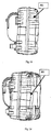
- Fig. 7 shows how parts of the communication unit 100 (see Fig. 1) can be compactly arranged for storage and transport in a portable case.
- the main segment 112 remains attached to the U-shaped carrier 502.
- the U-shaped carrier 502 encloses the RF transmit (Tx) electronics assembly 104 (shown in Fig. 1 - 5).
- Antenna segments 110 are stacked on the main segment 112. Antenna segments 110 preferably have patches of foam or rubber, or other suitable material, attached to the back, to provide separation between segments and protect them from scratching each other.
- the upper boom arm 301 with the feed horn and receiver assembly 103 is shown on top of the uppermost antenna segment and the lower boom arm 311 is shown adjacent the U-shaped carrier 502.
- Fig. 8 shows a cut-away view of the communication unit components of Fig. 7, arranged in the same manner as described in Fig. 7, in a portable case 801.
- the case 801 has a bottom half 802 and top half 803.
- the case has an impact-resistant outer shell 805 and is filled with protective foam 804 with cutouts for the individual components of the communication unit.
- Fig. 9 shows a cut-away view of the baseband housing 105 in which the baseband unit 901 is suspended by means of 8 shock absorbers 903.
- the baseband unit 901 contains the components needed to process data to and from a laptop computer or similar device into form suitable for the RF transmit (Tx) electronics assembly 104 and the feed horn and receiver assembly 103 (see Figs. 1-5).
- Fig. 10 shows a cut-away view of a portable case 801 containing the baseband housing 105 and the remaining two antenna segments 110.
- the case 801 is filled with protective foam 804, which surrounds the baseband housing 105 and antenna segments 110, providing shock and vibration protection. Therefore, during transportation, the baseband unit 901 (see Fig. 9) is protected from shock and vibration by impact-resistant outer shell 805, the protective foam 804 and the shock absorbers 903 (see Fig. 9).
- the boom assembly 102 is detached separated into two parts and the antenna segments 110 are separated.
- the main segment 112 with U-shaped carrier 502, RF transmit (Tx) electronics assembly 104, elevation gear 504, with elevation rod 505 and elevation motor 506 are removed from the rotatable platform 509, folded down and placed in one case 801 together with 3 antenna segments 110 and the boom assembly 102.
- the baseband housing 105 with its legs 106 folded is placed into the other case 801 with the 2 remaining antenna segments 110.
- the communications unit 100 has a 24 V DC input for connection to a vehicle battery or generator, for example.
- the communications unit 100 may be powered by 110/220 V AC.
- Fig. 11 shows the external view of the case 801 with the two parts 802 and 803 of the case 801 closed together and secured with straps 1103.
- the external surface of the case has channels through which the straps 1103 pass.
- the bottom surface of the case 801 is ergonomically shaped for greater comfort when the case 801 is worn as a backpack, either with shoulder straps attached directly to the case 801 or with a MOLLE frame (see below).
- Fig. 12 shows the front (or top) view of the case 801 indicating the location of the lifting handles 1201.
- the case 801 is shown mounted on a carriage 1205 with wheels 1208.
- the carriage 1205 is connected to the case 801 by straps 1103.
- the frame of the carriage 1205 can simply pass under the straps 1103 or, as shown in the Figure, the straps can pass through loops 1206 on the carriage.
- Figs. 13-15 demonstrate the attachment of the case 801 to a MOLLE frame 1301. Straps 1302 are passed through the backside of the MOLLE frame 1301 and, together with case-securing straps 1103, (see Fig. 11) through the slots 1105 on case 801.
- the MOLLE frame 1301 may be connected to the case 801 by passing the case-securing straps 1103 through the frame portion 1305 of the MOLLE frame 1301.
- the straps 1103 would also pass through slots 1105 in the shell of the case 801 as they normally do to secure the two halves of the case together.
- the slots 1105 are positioned so that the straps 1103 are directly behind the shoulder 1601 and waist 1602 pads of the MOLLE frame 1301.
- the case 801 is attached to the MOLLE frame 1301 at points corresponding approximately to the shoulder and waist level of a person carrying the case 801 on their back.
- Fig. 15 shows a side view of the case 801, mounted on the MOLLE frame 1301.
- the MOLLE frame 1301 has shoulder pads 1601, waist pads 1602 and shoulder straps 1502.
- the MOLLE frame 1301 also includes attachment points for tools and accessories and, therefore, is especially useful in military and outdoor applications.
- the MOLLE frame Due to the size, weight and hard exterior of the case 801, it is preferable to use the MOLLE frame when carrying the case 801 over uneven terrain and/or for long distances.
- Figs. 16(a) and 16(b) show an alternate embodiment of the case 801 having additional slots 1604 (in addition to slots 1105, see Fig. 13).
- the shoulder and waist pads 1601, 1602 are attached to the case 801 by passing the straps of the shoulder and waist pads 1601, 1602 through slots 1105 and 1604.
- the conversion into a backpack is completed by adding the shoulder straps 1701 as shown in Figs. 17(a) and 17(b).
- the ends of the shoulder straps 1701 are attached to case 801 by passing the strap ends through slots 1704.
- the case 801 can be carried as a backpack (however, without a MOLLE frame, in contrast to the embodiment of Figs. 13-15).
- a soft carrying handle 1605 may also be attached to the case 801 by passing the ends thereof through slots 1606. This handle 1605 is intended for short handling before the case 801 is worn as a backpack.
- Figs. 18 and 19 show side and three-quarter views of the case 801 with the shoulder straps 1701, waist pads 1602 and shoulder pads 1601 attached.
- the cases 801 are made of any suitable flexible, impact-resistant material which is relatively light and resistant to UV, mildew and corrosion.
- the preferred means for fastening the shoulder straps 1701, shoulder and waist pads 1601, 1602, the MOLLE frame 1301, the wheeled carriage 1205 and the soft handle 1605 to the case 801 is by straps passed through slots 1105, 1704, 1604 in the shell of the case 801.
- alternate fastening means may be used.
- the case 801 may have threaded holes in its outer shell operative to receive screws, so that the shoulder straps 1701, shoulder and waist pads 1601, 1602, the MOLLE frame 1301, the wheeled carriage 1205 and/or the soft handle 1605 can be screwed to the case 801.
- Further examples of alternate fastening means include Velcro and/or any of a number of quick release mechanisms.
- case 801 can be attached to a carriage 1205, MOLLE frame 1301 and/or backpack pads 1601, 1602 and straps 1701.
- portions of the outer shell 805 at one end of the case 801 are cut out and wheels are mounted so that they form an integral part of the case 801.
- a soft handle 1605 is fastened to the case 801 at the other end as shown in Figs. 17, 17(a) and 18, so that the case 801 can be wheeled along in a manner similar to the embodiment of Fig. 12.
- case 801 has two halves 802 and 803, it will be readily apparent to persons skilled in the art that many alternate embodiments of the case will fall within the scope of the invention.
- the case 801 could have a hollow "container" portion and a lid.
- lid and the hollow "container" portion may be connected by a hinge (the two halves 802 and 803 of the preferred embodiment may also be connected by a hinge).
- the invention contains novel features both in the communication unit itself, as well as in the packaging for stowage and transportation.
- they include the shape and configuration of the antenna segments, the two-part boom/feed assembly with quick-connect devices, the RF carrier hinged design, the integration of the azimuth alignment motorized platform with the baseband housing, the baseband housing with foldable legs for tripod-like stability and the shock absorbers for the BB unit itself, all of which cooperate to form a communications system that can be stowed in two airline checkable cases.
- the novel features include the hard-shell cases, which are capable of being used as an airline checkable suitcase, as a wheeled case, as a backpack mounted on a MOLLE frame, as a backpack without the MOLLE frame.
- each case is 68,6 cm x 49,5 cm x 33,5 cm (27" x 19.5" x 13.2"), and the mass of each case, including all the communication unit components stowed in it, does not exceed 22 kg. This enables easy manual transportation of the communication unit.
Landscapes
- Engineering & Computer Science (AREA)
- Computer Networks & Wireless Communication (AREA)
- Signal Processing (AREA)
- Purses, Travelling Bags, Baskets, Or Suitcases (AREA)
- Aerials With Secondary Devices (AREA)
- Variable-Direction Aerials And Aerial Arrays (AREA)
- Details Of Aerials (AREA)
- Radio Relay Systems (AREA)
Applications Claiming Priority (1)
| Application Number | Priority Date | Filing Date | Title |
|---|---|---|---|
| US11/220,549 US7218289B2 (en) | 2005-09-08 | 2005-09-08 | Portable high-speed data and broadcast-quality video terminal for terrestrial and satellite communications |
Publications (2)
| Publication Number | Publication Date |
|---|---|
| EP1763142A2 true EP1763142A2 (de) | 2007-03-14 |
| EP1763142A3 EP1763142A3 (de) | 2012-09-19 |
Family
ID=37682052
Family Applications (1)
| Application Number | Title | Priority Date | Filing Date |
|---|---|---|---|
| EP06007920A Withdrawn EP1763142A3 (de) | 2005-09-08 | 2006-04-14 | Tragbares Video-Endgerät für terrestrische- und Satellitübertragung mit hoher Datenübertragungsgeschwindigkeit und Rundfunkqualität |
Country Status (2)
| Country | Link |
|---|---|
| US (3) | US7218289B2 (de) |
| EP (1) | EP1763142A3 (de) |
Cited By (2)
| Publication number | Priority date | Publication date | Assignee | Title |
|---|---|---|---|---|
| EP3686996A1 (de) * | 2014-12-02 | 2020-07-29 | Ubiquiti Inc. | Antennensystem mit mehreren paneelen |
| CN111653858A (zh) * | 2020-05-27 | 2020-09-11 | 上海卫星工程研究所 | 卫星大口径可展开天线定位安装方法 |
Families Citing this family (41)
| Publication number | Priority date | Publication date | Assignee | Title |
|---|---|---|---|---|
| US7764243B2 (en) * | 2006-08-16 | 2010-07-27 | Gatr Technologies | Antenna positioning system |
| US7598916B2 (en) * | 2006-10-23 | 2009-10-06 | Gilat Satellite Networks Ltd. | Quick deployed antenna system |
| USD638408S1 (en) * | 2007-08-31 | 2011-05-24 | Swe-Dish Satellite Systems Ab | Satellite reflector |
| US20090302081A1 (en) * | 2008-06-04 | 2009-12-10 | Steve Kriesel | Carrying case system providing multiple levels of protection |
| US20100245196A1 (en) * | 2009-03-25 | 2010-09-30 | Eyal Miron | Antenna positioning system |
| WO2010144831A2 (en) * | 2009-06-12 | 2010-12-16 | Strydesky Gregory L | Segmented antenna reflector |
| US8390527B2 (en) * | 2009-10-21 | 2013-03-05 | Winegard Company | Portable satellite dish antenna system |
| US8319697B2 (en) * | 2009-10-22 | 2012-11-27 | Winegard Company | Semi-permanent portable satellite antenna system |
| IL202732A0 (en) | 2009-12-15 | 2010-11-30 | Dotan Ltd | Tracking station base |
| US8505867B2 (en) * | 2010-03-03 | 2013-08-13 | Winegard Company | Portable, lightweight mount for a satellite antenna system |
| US8593329B2 (en) * | 2010-03-17 | 2013-11-26 | Tialinx, Inc. | Hand-held see-through-the-wall imaging and unexploded ordnance (UXO) detection system |
| US8373589B2 (en) * | 2010-05-26 | 2013-02-12 | Detect, Inc. | Rotational parabolic antenna with various feed configurations |
| WO2012142593A2 (en) * | 2011-04-14 | 2012-10-18 | Casagrande Charles L | Vacuum mount system for portable electronic device |
| US9350083B2 (en) | 2012-03-10 | 2016-05-24 | Harris Corporation | Portable satellite communication system |
| FR2989523B1 (fr) * | 2012-04-13 | 2014-05-02 | Thales Sa | Antenne a reflecteurs multiples pour satellite de telecommunications |
| US9136610B2 (en) * | 2012-10-30 | 2015-09-15 | Viasat, Inc. | Satellite antenna adapter for tripod |
| US9196950B1 (en) * | 2012-12-11 | 2015-11-24 | Siklu Communication ltd. | Systems and methods for vibration amelioration in a millimeter-wave communication network |
| US9570794B2 (en) * | 2013-03-18 | 2017-02-14 | Cubic Corporation | Support apparatus for an inflatable antenna |
| CN103682673B (zh) * | 2013-11-25 | 2015-10-07 | 南京中网卫星通信股份有限公司 | 卫星双反面箱式便携站馈源支架装置 |
| US9912070B2 (en) * | 2015-03-11 | 2018-03-06 | Cubic Corporation | Ground-based satellite communication system for a foldable radio wave antenna |
| US11208183B2 (en) * | 2015-06-02 | 2021-12-28 | Acr Electronics, Inc. | EPIRB having retention carriage strap for hands free carriage |
| US9979082B2 (en) | 2015-08-10 | 2018-05-22 | Viasat, Inc. | Method and apparatus for beam-steerable antenna with single-drive mechanism |
| CN105119041B (zh) * | 2015-09-20 | 2017-10-31 | 金华技物光电研究所有限公司 | 全范围定向天线系统 |
| US10418685B1 (en) * | 2016-03-31 | 2019-09-17 | L3 Technologies, Inc. | Flexed perimeter roller antenna positioner |
| GB201703442D0 (en) * | 2017-03-03 | 2017-04-19 | Global Invacom Ltd | Improvements to installation and location of an antenna assembly |
| US10629986B2 (en) * | 2017-08-03 | 2020-04-21 | Winegard Company | Portable antenna system with manual elevation adjustment |
| US10361737B2 (en) | 2017-09-07 | 2019-07-23 | Futurecom Systems Group, ULC | Portable communication system having modular components |
| RU190369U1 (ru) * | 2019-02-05 | 2019-06-28 | Общество с ограниченной ответственностью "Информационно-контрольные технологии и системы" | Антенное устройство спутниковой связи |
| US10847892B2 (en) * | 2019-03-18 | 2020-11-24 | Antenna World Inc. | Wide band log periodic reflector antenna for cellular and Wifi |
| CN110388547B (zh) * | 2019-07-12 | 2021-09-24 | 中国电子科技集团公司第三十八研究所 | 一种用于方舱的两维旋转平台 |
| GB2594104B8 (en) * | 2019-07-26 | 2024-11-13 | Nanjing Zhongwang Satellite Communications Co Ltd | Ultralight portable satellite station |
| US12456801B1 (en) | 2019-08-28 | 2025-10-28 | Airbus DS Government Solutions, Inc. | Container for shipping a satellite terminal |
| CN110740278B (zh) * | 2019-11-08 | 2020-06-26 | 泉州燕群广告有限公司 | 一种私人使用的太阳能供电的卫星电视接收器 |
| CN111276820B (zh) * | 2020-01-22 | 2021-02-09 | 杭州电子科技大学 | 一种钢丝绳牵引式大型天线俯仰角调节装置及其调节方法 |
| USD928752S1 (en) * | 2020-01-30 | 2021-08-24 | Voxx International Corporation | Television antenna |
| US12501975B2 (en) * | 2020-11-06 | 2025-12-23 | Galtronics Usa, Inc. | Protective antenna package and transport unit therefor |
| CN113067589B (zh) * | 2021-03-22 | 2023-04-07 | 贵州电网有限责任公司 | 一种便携式通信信号收集处理装置 |
| US11323147B1 (en) | 2021-06-07 | 2022-05-03 | Futurecom Systems Group, ULC | Reducing insertion loss in a switch for a communication device |
| US12095496B2 (en) | 2021-10-18 | 2024-09-17 | Futurecom Systems Group, ULC | Self-diagnostic systems and method for a transceiver |
| US12525698B2 (en) * | 2021-10-19 | 2026-01-13 | Viavi Solutions Inc. | Smart mount for coupling an antenna alignment device to an antenna |
| US12041533B2 (en) | 2022-05-10 | 2024-07-16 | Motorola Solutions, Inc. | System and method for configuring a portable communication system |
Citations (9)
| Publication number | Priority date | Publication date | Assignee | Title |
|---|---|---|---|---|
| US5633891A (en) | 1993-04-16 | 1997-05-27 | Trans Video Electronics, Inc. | Portable integrated satellite communications unit |
| US5749503A (en) | 1996-03-27 | 1998-05-12 | Eagle Creek, Inc. | Convertible luggage system |
| US5864481A (en) | 1996-01-22 | 1999-01-26 | Raytheon Company | Integrated, reconfigurable man-portable modular system |
| US6530507B2 (en) | 2001-07-19 | 2003-03-11 | Luggage America, Inc. | Convertible backpack |
| EP1380123A1 (de) | 2001-04-20 | 2004-01-14 | Swedish Satellite Systems AB | Kommunikationseinrichtung und link-system für die satellitenkommunikation |
| US20040088780A1 (en) | 2002-11-08 | 2004-05-13 | Shlomo Bachar | Personal protection system and method for using a personal protection system |
| US6742684B2 (en) | 2002-05-14 | 2004-06-01 | Luggage America, Inc. | Wheeled backpack |
| US20040113836A1 (en) | 2002-08-02 | 2004-06-17 | Donald Rickerson | Wearable satellite tracker |
| EP1440612A1 (de) | 2001-09-13 | 2004-07-28 | Swedish Satellite Systems AB | Mobil-satellitenstreckenendgerät |
Family Cites Families (21)
| Publication number | Priority date | Publication date | Assignee | Title |
|---|---|---|---|---|
| US922046A (en) * | 1908-02-10 | 1909-05-18 | Rubert Stewart Royce | Knapsack. |
| US3960300A (en) * | 1974-01-25 | 1976-06-01 | Dickler Paul J | Tamper-proof backpack |
| AT338453B (de) * | 1975-03-19 | 1977-08-25 | Arno Grunberger | Schultasche |
| US3995802A (en) * | 1975-11-10 | 1976-12-07 | Brian Johnston | Back pack suitcase |
| US4082208A (en) * | 1976-08-30 | 1978-04-04 | Lane Jr Gordon Brandon | Modular chest back pack |
| EP0293877B1 (de) * | 1987-06-03 | 1993-10-13 | Kabushiki Kaisha Toshiba | Tragbare parabolische Antenne |
| JPS6412702A (en) * | 1987-07-07 | 1989-01-17 | Toshiba Corp | Portable reception antenna system |
| DE68920184T2 (de) * | 1988-04-08 | 1995-06-22 | Toshiba Kawasaki Kk | Tragbare Antennenvorrichtung. |
| US5334990A (en) * | 1990-03-26 | 1994-08-02 | K-Star International Corp. | Ku-band satellite dish antenna |
| JPH0563323U (ja) * | 1992-02-12 | 1993-08-24 | 株式会社ニフコ | キャリアバッグ |
| US5760751A (en) * | 1994-12-30 | 1998-06-02 | Gipson; Richard L. | Portable satellite antenna mount |
| US5634576A (en) * | 1995-11-13 | 1997-06-03 | Armadilo Ltd. | Knapsack |
| DE69705868T4 (de) * | 1997-01-06 | 2003-07-24 | Global Act Ab, Torekov | Rucksack |
| US5945961A (en) * | 1998-03-04 | 1999-08-31 | Harris Corporation | Antenna dish system having constrained rotational movement |
| US6164505A (en) * | 1998-04-22 | 2000-12-26 | Holter; Dean S. | Harness for carrying a rigid case |
| US6325189B1 (en) * | 1999-01-25 | 2001-12-04 | Samsonite Corporation | Hybrid construction luggage case |
| CA2273583A1 (en) * | 1999-05-31 | 2000-11-30 | Lloyd Alter | Hard shell back pack |
| KR200210681Y1 (ko) * | 2000-07-22 | 2001-01-15 | 이기수 | 하드케이스 착탈식 배낭 |
| US6462718B1 (en) * | 2001-03-20 | 2002-10-08 | Netune Communications, Inc. | Steerable antenna assembly |
| CA2424774A1 (en) * | 2003-04-02 | 2004-10-02 | Norsat International Inc. | Collapsible antenna assembly for portable satellite terminals |
| US20060144885A1 (en) * | 2004-12-15 | 2006-07-06 | Joris Smeuninx | Backpack with segmented construction body protecting features |
-
2005
- 2005-09-08 US US11/220,549 patent/US7218289B2/en not_active Expired - Fee Related
-
2006
- 2006-04-14 EP EP06007920A patent/EP1763142A3/de not_active Withdrawn
- 2006-05-12 US US11/308,838 patent/US20070052607A1/en not_active Abandoned
-
2007
- 2007-04-25 US US11/740,108 patent/US20070241155A1/en not_active Abandoned
Patent Citations (9)
| Publication number | Priority date | Publication date | Assignee | Title |
|---|---|---|---|---|
| US5633891A (en) | 1993-04-16 | 1997-05-27 | Trans Video Electronics, Inc. | Portable integrated satellite communications unit |
| US5864481A (en) | 1996-01-22 | 1999-01-26 | Raytheon Company | Integrated, reconfigurable man-portable modular system |
| US5749503A (en) | 1996-03-27 | 1998-05-12 | Eagle Creek, Inc. | Convertible luggage system |
| EP1380123A1 (de) | 2001-04-20 | 2004-01-14 | Swedish Satellite Systems AB | Kommunikationseinrichtung und link-system für die satellitenkommunikation |
| US6530507B2 (en) | 2001-07-19 | 2003-03-11 | Luggage America, Inc. | Convertible backpack |
| EP1440612A1 (de) | 2001-09-13 | 2004-07-28 | Swedish Satellite Systems AB | Mobil-satellitenstreckenendgerät |
| US6742684B2 (en) | 2002-05-14 | 2004-06-01 | Luggage America, Inc. | Wheeled backpack |
| US20040113836A1 (en) | 2002-08-02 | 2004-06-17 | Donald Rickerson | Wearable satellite tracker |
| US20040088780A1 (en) | 2002-11-08 | 2004-05-13 | Shlomo Bachar | Personal protection system and method for using a personal protection system |
Cited By (3)
| Publication number | Priority date | Publication date | Assignee | Title |
|---|---|---|---|---|
| EP3686996A1 (de) * | 2014-12-02 | 2020-07-29 | Ubiquiti Inc. | Antennensystem mit mehreren paneelen |
| CN111653858A (zh) * | 2020-05-27 | 2020-09-11 | 上海卫星工程研究所 | 卫星大口径可展开天线定位安装方法 |
| CN111653858B (zh) * | 2020-05-27 | 2021-07-23 | 上海卫星工程研究所 | 卫星大口径可展开天线定位安装方法 |
Also Published As
| Publication number | Publication date |
|---|---|
| EP1763142A3 (de) | 2012-09-19 |
| US20070241155A1 (en) | 2007-10-18 |
| US7218289B2 (en) | 2007-05-15 |
| US20070052612A1 (en) | 2007-03-08 |
| US20070052607A1 (en) | 2007-03-08 |
Similar Documents
| Publication | Publication Date | Title |
|---|---|---|
| US7218289B2 (en) | Portable high-speed data and broadcast-quality video terminal for terrestrial and satellite communications | |
| US9913516B2 (en) | Mobile storage unit | |
| US7237750B2 (en) | Autonomous, back-packable computer-controlled breakaway unmanned aerial vehicle (UAV) | |
| US6134105A (en) | Portable command center | |
| US8368606B1 (en) | Trailer mounted satellite system | |
| KR101804333B1 (ko) | 방송모듈 및/또는 접을 수 있는 아암을 갖는 무인 비행체 | |
| US8733766B2 (en) | Convertible conveyance method and apparatus | |
| US20040196207A1 (en) | Collapsible antenna assembly for portable satellite terminals | |
| CN107651182A (zh) | 一种多功能便携式多旋翼无人机 | |
| EP2543109B1 (de) | Transportierbare satellitenantenne | |
| US10353427B1 (en) | Carrying case for a laptop computer | |
| CN111994255B (zh) | 一种单兵轻小型航测无人机及单兵轻小型航测无人机系统 | |
| Hunyadi et al. | A commercial off the shelf (COTS) packet communications subsystem for the Montana EaRth-Orbiting Pico-Explorer (MEROPE) CubeSat | |
| CN207819916U (zh) | 一种易于携带的野战卫星通信单兵站 | |
| US20170196346A1 (en) | Backpack for Smart Self-Balancing Electric Scooter | |
| CN221599426U (zh) | 一种背负式通信设备折叠背包 | |
| CN119344551A (zh) | 多旋翼无人机便携式背包及便携方法 | |
| US12004647B2 (en) | Apparatus for carrying production sound mixing components | |
| CN220545006U (zh) | 基于收发信机的Ku/Ka双频段卫星通信背负站 | |
| CN112689464A (zh) | 具有多层级模块化设计和可连结箱的模块化行李系统 | |
| CN221575379U (zh) | 一种频率干扰便携式设备 | |
| CN118659110A (zh) | 一种便携式天线设备 | |
| US20250183523A1 (en) | Multi-purpose accessory system for wireless communication device | |
| CN117832804A (zh) | 背负式卫星通信方法及天线设备 | |
| CN210578547U (zh) | 一种机动式对空通信系统 |
Legal Events
| Date | Code | Title | Description |
|---|---|---|---|
| PUAI | Public reference made under article 153(3) epc to a published international application that has entered the european phase |
Free format text: ORIGINAL CODE: 0009012 |
|
| AK | Designated contracting states |
Kind code of ref document: A2 Designated state(s): AT BE BG CH CY CZ DE DK EE ES FI FR GB GR HU IE IS IT LI LT LU LV MC NL PL PT RO SE SI SK TR |
|
| AX | Request for extension of the european patent |
Extension state: AL BA HR MK YU |
|
| RIC1 | Information provided on ipc code assigned before grant |
Ipc: H04B 1/08 20060101ALI20120427BHEP Ipc: H04B 1/38 20060101ALI20120427BHEP Ipc: H04B 1/036 20060101AFI20120427BHEP |
|
| PUAL | Search report despatched |
Free format text: ORIGINAL CODE: 0009013 |
|
| AK | Designated contracting states |
Kind code of ref document: A3 Designated state(s): AT BE BG CH CY CZ DE DK EE ES FI FR GB GR HU IE IS IT LI LT LU LV MC NL PL PT RO SE SI SK TR |
|
| AX | Request for extension of the european patent |
Extension state: AL BA HR MK YU |
|
| RIC1 | Information provided on ipc code assigned before grant |
Ipc: H04B 1/38 20060101ALI20120816BHEP Ipc: H04B 1/036 20060101AFI20120816BHEP Ipc: H04B 1/08 20060101ALI20120816BHEP |
|
| STAA | Information on the status of an ep patent application or granted ep patent |
Free format text: STATUS: THE APPLICATION HAS BEEN WITHDRAWN |
|
| 18W | Application withdrawn |
Effective date: 20130322 |