EP1762875A1 - Autofocus imaging optical system and image pickup device - Google Patents
Autofocus imaging optical system and image pickup device Download PDFInfo
- Publication number
- EP1762875A1 EP1762875A1 EP06120475A EP06120475A EP1762875A1 EP 1762875 A1 EP1762875 A1 EP 1762875A1 EP 06120475 A EP06120475 A EP 06120475A EP 06120475 A EP06120475 A EP 06120475A EP 1762875 A1 EP1762875 A1 EP 1762875A1
- Authority
- EP
- European Patent Office
- Prior art keywords
- optical system
- lens unit
- focus
- image pickup
- image
- Prior art date
- Legal status (The legal status is an assumption and is not a legal conclusion. Google has not performed a legal analysis and makes no representation as to the accuracy of the status listed.)
- Granted
Links
- 230000003287 optical effect Effects 0.000 title claims abstract description 139
- 238000003384 imaging method Methods 0.000 title claims description 17
- 238000001514 detection method Methods 0.000 claims abstract description 90
- 230000002093 peripheral effect Effects 0.000 claims abstract description 16
- 238000006073 displacement reaction Methods 0.000 claims description 18
- 230000007423 decrease Effects 0.000 abstract description 13
- 238000000034 method Methods 0.000 description 7
- 210000001747 pupil Anatomy 0.000 description 6
- 230000014509 gene expression Effects 0.000 description 5
- 238000013459 approach Methods 0.000 description 1
- 238000005516 engineering process Methods 0.000 description 1
- 238000012986 modification Methods 0.000 description 1
- 230000004048 modification Effects 0.000 description 1
- 230000000087 stabilizing effect Effects 0.000 description 1
- 238000002834 transmittance Methods 0.000 description 1
Images


Classifications
-
- G—PHYSICS
- G02—OPTICS
- G02B—OPTICAL ELEMENTS, SYSTEMS OR APPARATUS
- G02B7/00—Mountings, adjusting means, or light-tight connections, for optical elements
- G02B7/28—Systems for automatic generation of focusing signals
- G02B7/34—Systems for automatic generation of focusing signals using different areas in a pupil plane
-
- G—PHYSICS
- G02—OPTICS
- G02B—OPTICAL ELEMENTS, SYSTEMS OR APPARATUS
- G02B27/00—Optical systems or apparatus not provided for by any of the groups G02B1/00 - G02B26/00, G02B30/00
- G02B27/10—Beam splitting or combining systems
- G02B27/108—Beam splitting or combining systems for sampling a portion of a beam or combining a small beam in a larger one, e.g. wherein the area ratio or power ratio of the divided beams significantly differs from unity, without spectral selectivity
-
- G—PHYSICS
- G02—OPTICS
- G02B—OPTICAL ELEMENTS, SYSTEMS OR APPARATUS
- G02B27/00—Optical systems or apparatus not provided for by any of the groups G02B1/00 - G02B26/00, G02B30/00
- G02B27/10—Beam splitting or combining systems
- G02B27/12—Beam splitting or combining systems operating by refraction only
- G02B27/123—The splitting element being a lens or a system of lenses, including arrays and surfaces with refractive power
-
- G—PHYSICS
- G02—OPTICS
- G02B—OPTICAL ELEMENTS, SYSTEMS OR APPARATUS
- G02B27/00—Optical systems or apparatus not provided for by any of the groups G02B1/00 - G02B26/00, G02B30/00
- G02B27/10—Beam splitting or combining systems
- G02B27/14—Beam splitting or combining systems operating by reflection only
- G02B27/143—Beam splitting or combining systems operating by reflection only using macroscopically faceted or segmented reflective surfaces
-
- G—PHYSICS
- G02—OPTICS
- G02B—OPTICAL ELEMENTS, SYSTEMS OR APPARATUS
- G02B27/00—Optical systems or apparatus not provided for by any of the groups G02B1/00 - G02B26/00, G02B30/00
- G02B27/10—Beam splitting or combining systems
- G02B27/14—Beam splitting or combining systems operating by reflection only
- G02B27/144—Beam splitting or combining systems operating by reflection only using partially transparent surfaces without spectral selectivity
-
- G—PHYSICS
- G02—OPTICS
- G02B—OPTICAL ELEMENTS, SYSTEMS OR APPARATUS
- G02B27/00—Optical systems or apparatus not provided for by any of the groups G02B1/00 - G02B26/00, G02B30/00
- G02B27/10—Beam splitting or combining systems
- G02B27/14—Beam splitting or combining systems operating by reflection only
- G02B27/145—Beam splitting or combining systems operating by reflection only having sequential partially reflecting surfaces
-
- G—PHYSICS
- G02—OPTICS
- G02B—OPTICAL ELEMENTS, SYSTEMS OR APPARATUS
- G02B27/00—Optical systems or apparatus not provided for by any of the groups G02B1/00 - G02B26/00, G02B30/00
- G02B27/10—Beam splitting or combining systems
- G02B27/16—Beam splitting or combining systems used as aids for focusing
-
- G—PHYSICS
- G02—OPTICS
- G02B—OPTICAL ELEMENTS, SYSTEMS OR APPARATUS
- G02B5/00—Optical elements other than lenses
- G02B5/20—Filters
- G02B5/205—Neutral density filters
-
- G—PHYSICS
- G03—PHOTOGRAPHY; CINEMATOGRAPHY; ANALOGOUS TECHNIQUES USING WAVES OTHER THAN OPTICAL WAVES; ELECTROGRAPHY; HOLOGRAPHY
- G03B—APPARATUS OR ARRANGEMENTS FOR TAKING PHOTOGRAPHS OR FOR PROJECTING OR VIEWING THEM; APPARATUS OR ARRANGEMENTS EMPLOYING ANALOGOUS TECHNIQUES USING WAVES OTHER THAN OPTICAL WAVES; ACCESSORIES THEREFOR
- G03B13/00—Viewfinders; Focusing aids for cameras; Means for focusing for cameras; Autofocus systems for cameras
- G03B13/32—Means for focusing
- G03B13/34—Power focusing
- G03B13/36—Autofocus systems
-
- H—ELECTRICITY
- H04—ELECTRIC COMMUNICATION TECHNIQUE
- H04N—PICTORIAL COMMUNICATION, e.g. TELEVISION
- H04N23/00—Cameras or camera modules comprising electronic image sensors; Control thereof
- H04N23/60—Control of cameras or camera modules
- H04N23/67—Focus control based on electronic image sensor signals
- H04N23/672—Focus control based on electronic image sensor signals based on the phase difference signals
Definitions
- FIG. 4 is a cross sectional view illustrating an image plane circumference beam with the splitting optical system 3 being displaced by a certain distance from the aperture stop 2.
- the reference numeral A represents a cross section at the aperture stop 2
- the reference numeral B represents a cross section at the splitting optical system 3
- the reference numeral D represents an image plane circumference beam
- the reference numeral h represents a height of an off-axis principal ray.
- FIG. 13 shows a configuration of an image pickup device of a fourth embodiment.
- a magnification lens unit 21 is disposed behind the focus lens unit 1 within the focus optical system 11.
- Focus detection means 22 for detecting a position of the focus lens unit 1 and zoom detection means 23 for detecting a position of the magnification lens unit 21 are provided, and their output are connected to the correction computing means 14.
Landscapes
- Physics & Mathematics (AREA)
- General Physics & Mathematics (AREA)
- Optics & Photonics (AREA)
- Spectroscopy & Molecular Physics (AREA)
- Engineering & Computer Science (AREA)
- Multimedia (AREA)
- Signal Processing (AREA)
- Focusing (AREA)
- Automatic Focus Adjustment (AREA)
- Adjustment Of Camera Lenses (AREA)
- Studio Devices (AREA)
Abstract
Description
- The present invention relates to an autofocus imaging optical system which includes a splitting optical system in an optical path, splits a light beam in an image pickup optical system for focus state detection and detects a focus state of an image pickup lens, and to an optical apparatus, image pickup device and the like including the autofocus imaging optical system.
- For auto-focusing (AF) technologies in a photographic device such as a still camera or video camera, various approaches have been proposed hitherto. Especially, for example in
Japanese Patent Application Laid-Open Nos. 2003-279842 2003-279846 2003-279847 2003-287673 - However, if a light beam used for image pickup is split for focus detection as described above, transmittance in an image pickup device may decrease and T number may increase. Therefore, an image becomes darker or an exposure time increases due to the insufficient light amount. Then, a more amount of light for focus detection may be required to improve focus accuracy or to enable to range the subject in a low illuminance condition. Accordingly, the image may further become darker.
- It is an object of the present invention, overcoming problems above mentioned, to reduce a decrease in light amount for image pickup due to the focus detection while securing an amount of light for a focus detection system. Further, it is an object to realize an autofocus imaging optical system, optical apparatus and image pickup device which may provide a pictorial image having a sufficient amount of light, while keeping a higher AF accuracy even in a low illuminance condition.
- In order to achieve objects above described, according to the present invention, at least one splitting optical system having an ununiform reflectance is provided in an optical path on the image side of a focus lens unit, which allows a focus state to be detected using a light beam split by the splitting optical system.
- Further features of the present invention will become apparent from the following description of exemplary embodiments with reference to the attached drawings.
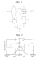
- FIG. 1 shows a configuration of a first embodiment;
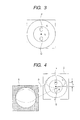
- FIG. 2 is a graph illustrating reflection distribution of a splitting optical system.
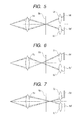
- FIG. 3 illustrates an area through which a light beam passes in a splitting optical system.
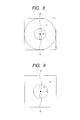
- FIG. 4 is a cross sectional view illustrating an image plane center beam and image plane circumference beam with a splitting optical system being displaced by a certain distance from an aperture stop.
- FIG. 5 illustrates an optical path in a focus state according to a phase difference method.
- FIG. 6 illustrates the optical path in a front focus state according to the phase difference method.
- FIG. 7 illustrates the optical path in a rear focus state according to the phase difference method.
- FIG. 8 illustrates an area through which a light beam passes in a splitting optical system.
- FIG. 9 illustrates an area through which a light beam passes in a splitting optical system.
- FIG. 10 shows a configuration of a third embodiment.
- FIG. 11 illustrates amounts of light incident on an image pickup system for a full-aperture state and a stopped down state in a splitting optical system in which the reflectance differs between in the central portion and the circumferential portion.
- FIG. 12 illustrates amounts of light incident on an image pickup system for a full-aperture state and a stopped down state in a splitting optical system having constant reflectance.
- FIG. 13 shows a configuration of a fourth embodiment.
- FIG. 14 is a cross sectional view illustrating an image plane center beam and image plane circumference beam with the center light beam being split in the manner of pupil division.
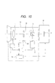
- FIG. 15 shows a configuration of a fifth embodiment.
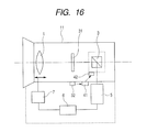
- FIG. 16 shows a configuration of a sixth embodiment.
- The present invention will be described in detail with respect to illustrated embodiments.
- (First Embodiment)
- Referring to FIG. 1, a configuration of a first embodiment is shown.
- Behind a
focus lens unit 1, anaperture stop 2, a splittingoptical system 3 having an ununiform reflectance and animage pickup element 4 are arranged. Focus detection means 5 is disposed in the splitting/reflecting direction of the splittingoptical system 3 such as a half mirror. An output of the focus detection means 5 is connected to computing means 6, and an output of the computing means 6 is connected to driving means 7. The driving means 7 drives thefocus lens unit 1. - This optical system has, for example, F number 1.8 and a diameter of the
aperture stop 2 of 30 mm in a full-aperture state. Since spacing between theaperture stop 2 and the splittingoptical system 3 is very small, a diameter of an area through which a light beam passes in the full-aperture state in the splittingoptical system 3 is 30 mm similar to that of the aperture stop. - The focus detection means 5 use a so-called phase difference method, and for a light beam used for focus detection, only a light beam passing through the inside of a portion having F number 5.4 is used.
- FIG. 2 shows reflectance characteristics of the splitting
optical system 3 in the central portion and circumferential portion. The longitudinal axis represents reflectance of the splittingoptical system 3, and the lateral axis represent a distance from an optical axis of the splittingoptical system 3. - The reflectance on the optical axis of the splitting
optical system 3 is 50 %, and the reflectance in a portion through which a light beam passes most far away from the optical axis (15 mm from the optical axis) is 0 %, and the reflectance in a portion coming close to the central portion becomes larger. - In the case of the focus detection means 5 using the phase difference method, a central portion R corresponds to a minimal area containing the entirety of a light beam actually used for focus detection. A peripheral portion S corresponds to an area through which a light beam passes excluding the central portion R. Since the light beam used for focus detection is only a light beam passing through a portion near side to the optical axis from the portion having F number 5.4, the central portion R may be defined as an area with a distance of below 5 mm from the optical axis, and the peripheral portion S may be defined as an area located between 5 and 15 mm from the optical axis.
- FIG. 3 shows an area through which a light beam passes in the splitting
optical system 3. In the phase difference method, areas P and Q show areas of a light beam used for focus detection by the focus detection means 5. - In this case, an average reflectance Rr in the central portion R is 35 %, and an average reflectance Sr in the peripheral portion S is 5 %. An area Rq of the central portion R is 78.5 mm2, an area Sq of the peripheral portion S is 628.3 mm2, and the total area Q of the central portion R and peripheral portion S, Q = Rq + Sq, equals 706.8 mm2.
- In fact, by configuring the average reflectance Rr being 35 %, a sufficient amount of light for focus detection is secured for the focus detection means 5. A ratio W1 of an amount of light directed to the
image pickup element 4 and a ratio W2 of an amount of light directed to the of the focus detection means 5 are expressed by the following expressions (1) and (2): -

-

- Therefore, 89 % of the amount of light is directed to the
image pickup element 4, and a decrease in the amount of light of the subject image light on the image pickup side may be reduced to 11%. - In this embodiment, while a necessary light beam for focus detection is efficiently split to the focus detection means 5, the reflecting characteristic of the splitting
optical system 3 is specified so as to minimize the decrease in the amount of light for image pickup. Especially, when only a part of a light beam is used for focus detection, as in the case of the focus detection means 5 using the phase difference method, reflectance of the splittingoptical system 3 is set higher in a portion through which a light beam passes, and set lower in the other portions. Accordingly, securement of a sufficient amount of light for focus detection for the focus detection means 5 and a reduction of a decrease in the amount of light for image pickup may be achieved by reflecting selectively a light beam only for focus detection to the focus detection means 5. - FIG. 4 is a cross sectional view illustrating an image plane circumference beam with the splitting
optical system 3 being displaced by a certain distance from theaperture stop 2. The reference numeral A represents a cross section at theaperture stop 2, the reference numeral B represents a cross section at the splittingoptical system 3, the reference numeral D represents an image plane circumference beam, and the reference numeral h represents a height of an off-axis principal ray. - Let "d" be an optical path length between the
aperture stop 2 and the splittingoptical system 3, let "α" be an off-axis principal ray angle at theaperture stop 2, and then, an off-axis principal ray incident height h is approximately proportional to d, and the following expression is satisfied. -

- The larger the off-axis principal ray height h is, the smaller an area where the image plane circumference beam D passes through the central portion R having a higher reflectance becomes, and accordingly, the focus detection means 5 may not be supplied with a sufficient amount of light for focus detection. Therefore, the length d between the splitting
optical system 3 and theaperture stop 2 is set shorter, and the off-axis principal ray height h is set lower. With this configuration, an area where the image plane circumference beam D also passes through the areas P and Q used for focus detection can be made larger. Therefore, the sufficient amount of light for focus detection relative to the image plane peripheral portion may be brought into incidence on the focus detection means 5. - (Second Embodiment)
- Referring to FIG. 5, an optical path in a focus state of the focus detection means 5 is illustrated, in FIG. 6, the optical path in a front focus state is illustrated, and in FIG. 7, the optical path in a rear focus state is illustrated.
- A
first lens unit 5a in the focus detection means 5 images a split light beam. The light beam is imaged on aprimary image plane 5b by thisfirst lens unit 5a. - Two
second lens units primary image plane 5b. A light beam is imaged on twosensors second lens units - In the so-called front focus state shown in FIG. 6, a focal position of the imaging lens 4a is located on the subject side of the
primary image plane 5b. In the so-called rear focus state in FIG. 7, the focal position of the imaging lens 4a is located on the image side of theprimary image plane 5b. - As shown in FIG. 5, when a light beam passed through the imaging lens 4a is imaged on the
primary image plane 5b, a secondary image is formed on a predetermined position of each of thesensors - On the contrary, as shown in FIG. 6, when a light beam passed through the imaging lens 4a is imaged ahead of the
primary image plane 5b, a phase difference relative to a reference image position is produced at thesensors - FIG. 7 shows a case in which a light beam is imaged at the back of the
image plane 5b. Then, the phase difference of the image is opposite to that in FIG. 6. - FIG. 8 illustrates an area through which a light beam passes in the splitting
optical system 3. Areas P and Q show an area of a light beam which is split in the manner of pupil division by thesecond lens units - A central portion R illustrates a circle of a minimal radius R (F number: 5.4, radius: 5 mm) which includes the area P and Q used for focus detection and is concentric with the splitting
optical system 3. A peripheral portion S illustrates an area through which a light beam passes excluding the central portion R (F number: 1.8, radius: 15 mm). - In the phase difference detection method, an incident light beam on the focus detection means 5 is split in the manner of pupil division by the
second lens units - Therefore, the splitting
optical system 3 as in the first embodiment is configured to have a higher reflectance in the central portion R which includes the areas P and Q in FIG. 9, of the minimal diameter and a lower reflectance in the peripheral portion S excluding the central portion R. - As described above, by configuring the reflectance of the splitting
optical system 3 so as to selectively reflect a light beam only used for focus detection in a focus detection system, a sufficient amount of light for the focus detection system can be secured and a decrease in an amount of light for image pickup can be reduced. - It may be desirable that reflectance distribution satisfies the following expressions:
-

-

optical system 3 at a point at a distance L from the center of the splittingoptical system 3, and K is reflectance necessary for focus detection when reflectance of the splittingoptical system 3 is constant, and r is a radius of the central portion R. - Since an average reflectance in the areas P and Q can be set larger than the reflectance K by satisfying of the expression (4), a sufficient amount of light for focus detection may be directed to the focus detection means 5. Also, since much of light beam not used for focus detection in a portion excluding the areas P and Q can be directed to an image pickup system by satisfying of the expression (5), a decrease in an amount of light of the subject image for the image pickup system may be reduced.
- (Third Embodiment)
- FIG. 10 shows a configuration of an image pickup device of a third embodiment. The like elements as those in FIG. 1 are denoted with the like reference signs. An image pickup device includes an autofocus
optical system 11 and animage pickup portion 12. The autofocusoptical system 11 includes thefocus lens unit 1, theaperture stop 2 and the splittingoptical system 3. Focus detection means 5 is disposed in splitting direction of the splittingoptical system 3. An output of the focus detection means 5 is connected to computing means 6. An output of the computing means 6 is connected to driving means 7. The driving means 7 drives the focus displacement means 1. Further, aperture stop detection means 13 for detecting a position of theaperture stop 2 is provided. An output of the aperture stop detection means 13 is connected through correction computing means 14 to theimage pickup portion 12. - The aperture stop detection means 13 detects a stop value of the
aperture stop 2, and based on the stop value, the correction value computing means 14 computes a correction value for image plane correction. The computed value is transmitted to theimage pickup portion 12, and theimage pickup portion 12 corrects for image plane luminance. - FIG. 11 shows an amount of incident light on the
image pickup system 12 in a full-aperture state of theaperture stop 2 and an amount of incident light on theimage pickup portion 12 in a stopped down state of theaperture stop 2, when, in the splittingoptical system 3, reflectance is varied depending on a position on a splitting surface thereof. The longitudinal axis represents reflectance of the splittingoptical system 3, and the lateral axis represents a position on the splittingoptical system 3 from the periphery to the center, then to the periphery. Further, in a portion shown by vertical lines, the amount of incident light on theimage pickup portion 12 in the full-aperture state of theaperture stop 2 is shown, and in a portion shown by diagonal lines, the amount of incident light on theimage pickup portion 12 in the stopped down state of theaperture stop 2 is represented. - FIG. 12 shows an amount of incident light on the
image pickup portion 12 in the full-aperture state of theaperture stop 2 and an amount of incident light on theimage pickup portion 12 in the stopped down state of theaperture stop 2, when, as in a conventional embodiment, reflectance of the splittingoptical system 3 is constant. - Comparing between FIG. 11 and FIG. 12, a decrease from the amount of light in the full-aperture state of the
aperture stop 2 to that in the stopped down state, in the case of the splittingoptical system 3 having the ununiform reflectance, is larger than a decrease in the case of the splittingoptical system 3 having the constant reflectance. Therefore, in the case of the splittingoptical system 3 having the ununiform reflectance, it is necessary to prevent a rapid decrease in the amount of light on an image plane at the time of theaperture stop 2 being stopped down by increasing a gain electrically when the detected aperture stop value goes large. - (Fourth Embodiment)
- FIG. 13 shows a configuration of an image pickup device of a fourth embodiment. In addition to the third embodiment shown in FIG. 10, a
magnification lens unit 21 is disposed behind thefocus lens unit 1 within the focusoptical system 11. Focus detection means 22 for detecting a position of thefocus lens unit 1 and zoom detection means 23 for detecting a position of themagnification lens unit 21 are provided, and their output are connected to the correction computing means 14. - In this fourth embodiment, the positions of the
focus lens unit 1 and themagnification lens unit 21 are obtained by the focus detection means 22 and the zoom detection means 23, respectively, a correction value for image plane correction is computed by the correction computing means 14, and then the resultant correction value is transmitted to theimage pickup portion 12 correct an image plane. - When an incident light beam on the splitting
optical system 3 varies due to change in pupil division caused by zoom and/or focus displacement, in the case of the splitting optical system having the ununiform reflectance, balance between an amount of light in the central portion and that in the peripheral portion varies with the displacement of the zoom and/or focus. - When zoom and/or focus value detected is such in that the balance between the amount of light in the central portion and that in the peripheral portion may be largely unbalanced, the balance between the amount of light in the central portion and that in the peripheral portion can be maintained by an electrical correction in a manner of axial symmetry with the center of an image plane being a reference.
- FIG. 14 illustrates optical paths of an image plane center beam and an image plane circumference beam in the case of the splitting
optical system 3 being displaced by a certain distance from theaperture stop 2. Theaperture stop 2 is shown by A, the splittingoptical system 3 by B, the image plane center beam by C, and the image plane circumference beam having an angle of field by D. - When the image plane center beam is split in the way of pupil division due to magnification by the
magnification lens unit 21, in the case where the splittingoptical system 3 having the ununiform reflectance is used, the image plane center beam C, in addition to pupil division, will pass through the central portion R having a higher reflectance, so that an amount of light decreases largely. - On the contrary, because the image plane circumference beam D passes through the peripheral portion S having a lower reflectance offset from the central portion R of the splitting
optical system 3, an amount of light of the image plane circumference beam becomes larger than the amount of light of the image plane center beam. - Therefore, by performing a correction so as to electrically raise a gain to the maximum extent possible in the center of an image plane and to gradually lower the gain toward the peripheral portion in the image plane, the balance of the whole image plane can be kept better.
- (Fifth Embodiment)
- Referring to FIG. 15, a configuration of an image pickup device of a fifth embodiment is shown. The similar elements as the elements of the third embodiment in FIG. 10 are denoted with the same reference signs. An image blur correction
optical system 31 is provided between thefocus lens unit 1 and the splittingoptical system 3 in the autofocusoptical system 11. Displacement detection means 32 for detecting an amount of displacement of the image blur correctionoptical system 31 is provided, and an output of the displacement detection means 32 is connected to the correction computing means 14. - A position of the image blur correction
optical system 31 is obtained by the displacement detection means 32, and based on this position, a correction value for image plane correction is computed by the correction computing means 14, thereby correcting an image plane at theimage pickup portion 12. - In this fifth embodiment, displacement of the image blur correction
optical system 31 may cause light incident on the splittingoptical system 3 to change. On the contrary, because the splittingoptical system 3 having a concentric reflectance distribution is fixed, the displacement of light incident on the splittingoptical system 3 may cause an amount of light incident on the image pickup system in the left, right, top and bottom of an image plane to become asymmetrical. - Therefore, depending on an amount of the displacement of the image blur correction
optical system 31, increasing electrically a gain to an arbitrary value at an arbitrary position in the image pickup portion may maintain balance of the amount of light in the entire image plane. - (Sixth Embodiment)
- FIG. 16 shows a configuration of a sixth embodiment. In addition to the fifth embodiment shown in FIG. 15, the output of the displacement detection means 32 of the image blur correction
optical system 31 is connected to drive computing means 41, and an output of the drive computing means 41 is connected to adrive motor 42 for driving the splittingoptical system 3. - A position of the image blur correction
optical system 31 is obtained by the displacement detection means 32, and a drive value for driving the splittingoptical system 3 is computed by the drive computing means 41. Based on the drive value computed, the splittingoptical system 3 is driven by thedrive motor 42. - Displacement of the image blur correction
optical system 31 may cause light beam incident on the splittingoptical system 3 to change. - Therefore, by displacing the splitting
optical system 3 so as to keep the symmetry of an amount of light on an image plane depending on the displacement of the image blur correctionoptical system 31, change in the amount of light due to image stabilizing may be corrected. In such a manner, balance of the amount of light on the entire image plane may be achieved. - As to the displacement of the splitting
optical system 3, even if the splittingoptical system 3 is displaced, the optical path length to the focus detection means 5 needs to be kept constant. Therefore, it is necessary for only the splittingoptical system 3 to be driven along a reflecting surface, or both the splittingoptical system 3 and the focus detection means 5 to be driven in up and down direction. - While the present invention has been described with reference to exemplary embodiments, it is to be understood that the invention is not limited to the disclosed exemplary embodiments. The scope of the following claims is to be accorded the broadest interpretation so as to encompass all such modifications and equivalent structures and functions.
An image pickup device in which reflectance in a central portion of the splitting optical system is configured large and that in a peripheral portion is configured small, to thereby selectively reflect only a light beam for focus detection in focus detection means and transmit the other portions of the light beam to the image pickup means so that a decrease in an amount of light for the image pickup means can be reduced while securing an amount of light for focus detection.
Claims (7)
- An optical apparatus, comprising:a focus lens unit for imaging a subject image;a splitting optical system for splitting a light beam from the subject disposed in an optical path on the image side of the focus lens unit;focus detection means for detecting a focus state of the subject image by using a light beam split in the splitting optical system; anddrive means for driving a focus lens unit to a focal position based on the detection result of the focus detection means,whereinreflectance of the splitting optical system has a distribution in which the reflectance is of the maximal value on an optical axis and lowered gradually away from the optical axis.
- The optical apparatus according to claim 1, wherein an aperture stop is disposed adjacent to the front of said splitting optical system.
- The optical apparatus according to claim 1, wherein said focus detection means comprises a optical system for focus detection including, in order from the object side, a first lens unit having positive refractive power for primary imaging and a second lens unit disposed symmetrically about the optical axis and having at least one pair of positive refractive power for secondary imaging.
- The optical apparatus according to claim 1, further comprising:an image blur correction optical system for correcting the subject image blur by vertically moving relative to the optical axis;position detection means for detecting a position of the image blur correction optical system;drive means for driving the splitting optical system vertically relative to the optical axis; andcontrol means for controlling the driving of the splitting optical system,wherein the control means displaces the splitting optical system based on a value detected by the position detection means.
- An optical apparatus, comprising:a focus lens unit for imaging a subject image;a split optical system for splitting a light beam from the subject and disposed in an optical path on an image side of the focus lens unit;focus detection means for detecting a focus state of the subject image by using a light beam split by the split optical system;drive means for driving a focus lens unit to a focal position based on a detection result of the focus detection means;image pickup means for taking the subject image imaged by the focus lens unit;image pickup means control means for controlling the image pickup means;aperture stop means for limiting an amount of light to the image pickup means; andaperture stop value detection means for detecting an aperture stop value of the aperture stop means,whereinthe image pickup means is able to change a gain; andthe image pickup means control means controls a gain of the image pickup means based on a value detected by the aperture stop value detection means.
- An optical apparatus, comprising:a focus lens unit for imaging the subject image;focus lens position detection means for detecting a position of the focus lens unit;a split optical system for splitting a light beam from the subject and disposed in an optical path on the image side of the focus lens unit;focus detection means for detecting a focus state of the subject image by using a light beam split in the split optical system;drive means for driving the focus lens unit;image pickup means for taking the subject image imaged by the focus lens unit;image pickup means control means for controlling the image pickup means;a magnification lens unit for magnifying the subject image; andmagnification lens position detection means for detecting a position of the magnification lens,whereinthe image pickup means control means electrically corrects change in an amount of light on the periphery based on values detected by the magnification lens position detection means and the focus lens position detection means.
- An optical apparatus, comprising:a focus lens unit for imaging a subject image;focus lens position detection means for detecting a position of the focus lens unit;a split optical system for splitting a light beam from the subject and disposed in an optical path on the image side of the focus lens unit;focus detection means for detecting a focus state of the subject image by using a light beam split in the splitting optical system;drive means for driving the focus lens unit;image pickup means for taking the subject image imaged by the focus lens unit;image pickup means control means for controlling the image pickup means;an image blur correction optical system for correcting the subject image blur by moving vertically relative to the optical axis; anddisplacement detection means for detecting a displacement of the image blur correction optical system,wherein the image pickup means control means electrically corrects change in an amount of asymmetrical peripheral light based on a value detected by the displacement detection means.
Applications Claiming Priority (1)
| Application Number | Priority Date | Filing Date | Title |
|---|---|---|---|
| JP2005266057A JP2007079055A (en) | 2005-09-13 | 2005-09-13 | Autofocus imaging optical system and imaging apparatus |
Publications (2)
| Publication Number | Publication Date |
|---|---|
| EP1762875A1 true EP1762875A1 (en) | 2007-03-14 |
| EP1762875B1 EP1762875B1 (en) | 2008-09-10 |
Family
ID=37467447
Family Applications (1)
| Application Number | Title | Priority Date | Filing Date |
|---|---|---|---|
| EP06120475A Not-in-force EP1762875B1 (en) | 2005-09-13 | 2006-09-12 | Autofocus imaging optical system and image pickup device |
Country Status (4)
| Country | Link |
|---|---|
| US (1) | US8135267B2 (en) |
| EP (1) | EP1762875B1 (en) |
| JP (1) | JP2007079055A (en) |
| DE (1) | DE602006002692D1 (en) |
Cited By (1)
| Publication number | Priority date | Publication date | Assignee | Title |
|---|---|---|---|---|
| EP1962499A3 (en) * | 2007-02-20 | 2010-09-01 | Canon Kabushiki Kaisha | Lens apparatus |
Families Citing this family (1)
| Publication number | Priority date | Publication date | Assignee | Title |
|---|---|---|---|---|
| AT509112B1 (en) * | 2009-12-10 | 2011-09-15 | Miba Gleitlager Gmbh | SLIDING LAYER |
Citations (4)
| Publication number | Priority date | Publication date | Assignee | Title |
|---|---|---|---|---|
| US4547663A (en) * | 1980-12-12 | 1985-10-15 | Canon Kabushiki Kaisha | Focus detecting apparatus with a compensation mask |
| JPH01133015A (en) * | 1987-11-18 | 1989-05-25 | Ricoh Co Ltd | Focus detector and its production |
| US6344639B1 (en) * | 1998-05-08 | 2002-02-05 | Asahi Kogaku Kogyo Kabushiki Kaisha | Beam splitter for automatic focusing device |
| US20050041949A1 (en) * | 2003-08-20 | 2005-02-24 | Canon Kabushiki Kaisha | Light amount adjusting apparatus, optical equipment, optical filter and image-taking apparatus |
Family Cites Families (18)
| Publication number | Priority date | Publication date | Assignee | Title |
|---|---|---|---|---|
| US4517666A (en) * | 1981-06-22 | 1985-05-14 | Tokyo Shibaura Denki Kabushiki Kaisha | Optical head |
| JPS63124219A (en) * | 1986-11-13 | 1988-05-27 | Kao Corp | Magnetic recording medium |
| JPH0337608A (en) * | 1989-07-04 | 1991-02-19 | Minolta Camera Co Ltd | Optical system for focus detection |
| US5157459A (en) * | 1989-08-29 | 1992-10-20 | Asahi Kogaku Kogyo Kabushiki Kaisha | Wave front aberration measuring apparatus |
| JPH03112472A (en) | 1989-09-26 | 1991-05-14 | Mitsubishi Heavy Ind Ltd | Apparatus for high pressure treatment |
| JP3112472B2 (en) * | 1990-09-26 | 2000-11-27 | オリンパス光学工業株式会社 | Object moving speed detecting device and camera image blur correcting device |
| JPH04215623A (en) * | 1990-12-14 | 1992-08-06 | Olympus Optical Co Ltd | Jiggle preventive device for camera |
| EP0669757B1 (en) * | 1994-02-28 | 2002-11-27 | Canon Kabushiki Kaisha | Image sensing apparatus |
| US20010050892A1 (en) * | 1997-07-11 | 2001-12-13 | Yoshitaka Takahashi | Optical disk apparatus compatible with different types of mediums |
| JPH11259893A (en) * | 1998-01-09 | 1999-09-24 | Sony Corp | Optical head, recording and / or reproducing apparatus, recording and / or reproducing method, and thickness detecting method |
| JP4106208B2 (en) * | 2001-10-04 | 2008-06-25 | シャープ株式会社 | Optical pickup device |
| JP2003279842A (en) | 2002-03-22 | 2003-10-02 | Fuji Photo Optical Co Ltd | Focus state detector for photographing lens |
| JP2003279846A (en) | 2002-03-25 | 2003-10-02 | Fuji Photo Optical Co Ltd | Focus state detector for photographing lens |
| JP2003279847A (en) | 2002-03-26 | 2003-10-02 | Fuji Photo Optical Co Ltd | Focus state detector for photographing lens |
| JP2003287673A (en) | 2002-03-27 | 2003-10-10 | Fuji Photo Optical Co Ltd | Focusing state detecting device for photographic lens |
| US7218591B2 (en) * | 2002-04-17 | 2007-05-15 | Sharp Kabushiki Kaisha | Optical pickup apparatus |
| JP3938097B2 (en) * | 2003-05-02 | 2007-06-27 | キヤノン株式会社 | Correction apparatus, imaging apparatus, correction method, computer-readable storage medium, and program |
| JP4323925B2 (en) * | 2003-10-27 | 2009-09-02 | キヤノン株式会社 | Optical equipment |
-
2005
- 2005-09-13 JP JP2005266057A patent/JP2007079055A/en active Pending
-
2006
- 2006-09-11 US US11/530,554 patent/US8135267B2/en not_active Expired - Fee Related
- 2006-09-12 DE DE602006002692T patent/DE602006002692D1/en active Active
- 2006-09-12 EP EP06120475A patent/EP1762875B1/en not_active Not-in-force
Patent Citations (4)
| Publication number | Priority date | Publication date | Assignee | Title |
|---|---|---|---|---|
| US4547663A (en) * | 1980-12-12 | 1985-10-15 | Canon Kabushiki Kaisha | Focus detecting apparatus with a compensation mask |
| JPH01133015A (en) * | 1987-11-18 | 1989-05-25 | Ricoh Co Ltd | Focus detector and its production |
| US6344639B1 (en) * | 1998-05-08 | 2002-02-05 | Asahi Kogaku Kogyo Kabushiki Kaisha | Beam splitter for automatic focusing device |
| US20050041949A1 (en) * | 2003-08-20 | 2005-02-24 | Canon Kabushiki Kaisha | Light amount adjusting apparatus, optical equipment, optical filter and image-taking apparatus |
Non-Patent Citations (1)
| Title |
|---|
| ANONYMOUS: "Improving the Efficiency and Image-Uniformity of a Simple Reflective Light Valve Projector. April 1980.", IBM TECHNICAL DISCLOSURE BULLETIN, vol. 22, no. 11, 1 April 1980 (1980-04-01), New York, US, pages 5062 - 5063, XP002412598 * |
Cited By (2)
| Publication number | Priority date | Publication date | Assignee | Title |
|---|---|---|---|---|
| EP1962499A3 (en) * | 2007-02-20 | 2010-09-01 | Canon Kabushiki Kaisha | Lens apparatus |
| US7852732B2 (en) | 2007-02-20 | 2010-12-14 | Canon Kabushiki Kaisha | Lens apparatus |
Also Published As
| Publication number | Publication date |
|---|---|
| EP1762875B1 (en) | 2008-09-10 |
| US8135267B2 (en) | 2012-03-13 |
| US20070076541A1 (en) | 2007-04-05 |
| JP2007079055A (en) | 2007-03-29 |
| DE602006002692D1 (en) | 2008-10-23 |
Similar Documents
| Publication | Publication Date | Title |
|---|---|---|
| KR101302271B1 (en) | Fish-eye lens and imaging device | |
| US4768052A (en) | Focus detecting device | |
| KR101395015B1 (en) | Camera, focus detection method and control method | |
| EP1843185B1 (en) | Objective lens with improved focusing operation | |
| EP2993506B1 (en) | Interchangeable lens apparatus, image capturing apparatus and system | |
| US20160349522A1 (en) | Imaging apparatus with two image sensors | |
| US20170059972A1 (en) | Projection optical system and projection type display apparatus using the same | |
| JP5179216B2 (en) | Zoom lens | |
| US6112029A (en) | Camera, exchangeable lens, and camera system | |
| US20150301317A1 (en) | Infrared camera apparatus | |
| CN102713713A (en) | Focusing device and focusing method | |
| EP0782026B1 (en) | Focus detecting apparatus | |
| EP1762875B1 (en) | Autofocus imaging optical system and image pickup device | |
| EP3079350A1 (en) | Imaging apparatus and method of controlling the same | |
| JP2005195786A (en) | Focus detection device and optical instrument using the same | |
| KR100942201B1 (en) | Focus detection device and control method | |
| US5497229A (en) | Photometering apparatus having a split light receiving device | |
| JP2008191391A (en) | Focus adjustment device, camera | |
| JP2015034859A (en) | Automatic focus adjustment lens device and photographing device | |
| US7689111B2 (en) | Optical apparatus | |
| US7502557B2 (en) | Finder optical system and imaging apparatus comprising the same | |
| JP2740749B2 (en) | Auto focus device | |
| JP2006220868A (en) | Camera with infrared detection mechanism | |
| JPS62106425A (en) | Focus detection optical system | |
| JPH0694972A (en) | Focusing system interlocking with trimming |
Legal Events
| Date | Code | Title | Description |
|---|---|---|---|
| PUAI | Public reference made under article 153(3) epc to a published international application that has entered the european phase |
Free format text: ORIGINAL CODE: 0009012 |
|
| AK | Designated contracting states |
Kind code of ref document: A1 Designated state(s): AT BE BG CH CY CZ DE DK EE ES FI FR GB GR HU IE IS IT LI LT LU LV MC NL PL PT RO SE SI SK TR |
|
| AX | Request for extension of the european patent |
Extension state: AL BA HR MK YU |
|
| 17P | Request for examination filed |
Effective date: 20070914 |
|
| AKX | Designation fees paid |
Designated state(s): DE FR GB |
|
| GRAP | Despatch of communication of intention to grant a patent |
Free format text: ORIGINAL CODE: EPIDOSNIGR1 |
|
| GRAS | Grant fee paid |
Free format text: ORIGINAL CODE: EPIDOSNIGR3 |
|
| GRAA | (expected) grant |
Free format text: ORIGINAL CODE: 0009210 |
|
| AK | Designated contracting states |
Kind code of ref document: B1 Designated state(s): DE FR GB |
|
| REG | Reference to a national code |
Ref country code: GB Ref legal event code: FG4D |
|
| REF | Corresponds to: |
Ref document number: 602006002692 Country of ref document: DE Date of ref document: 20081023 Kind code of ref document: P |
|
| PLBE | No opposition filed within time limit |
Free format text: ORIGINAL CODE: 0009261 |
|
| STAA | Information on the status of an ep patent application or granted ep patent |
Free format text: STATUS: NO OPPOSITION FILED WITHIN TIME LIMIT |
|
| 26N | No opposition filed |
Effective date: 20090611 |
|
| REG | Reference to a national code |
Ref country code: FR Ref legal event code: PLFP Year of fee payment: 10 |
|
| PGFP | Annual fee paid to national office [announced via postgrant information from national office to epo] |
Ref country code: DE Payment date: 20150930 Year of fee payment: 10 Ref country code: GB Payment date: 20150922 Year of fee payment: 10 |
|
| PGFP | Annual fee paid to national office [announced via postgrant information from national office to epo] |
Ref country code: FR Payment date: 20150928 Year of fee payment: 10 |
|
| REG | Reference to a national code |
Ref country code: DE Ref legal event code: R119 Ref document number: 602006002692 Country of ref document: DE |
|
| GBPC | Gb: european patent ceased through non-payment of renewal fee |
Effective date: 20160912 |
|
| REG | Reference to a national code |
Ref country code: FR Ref legal event code: ST Effective date: 20170531 |
|
| PG25 | Lapsed in a contracting state [announced via postgrant information from national office to epo] |
Ref country code: GB Free format text: LAPSE BECAUSE OF NON-PAYMENT OF DUE FEES Effective date: 20160912 Ref country code: DE Free format text: LAPSE BECAUSE OF NON-PAYMENT OF DUE FEES Effective date: 20170401 Ref country code: FR Free format text: LAPSE BECAUSE OF NON-PAYMENT OF DUE FEES Effective date: 20160930 |