EP1762810A2 - Corrosion resistant charged air cooler and process for making same - Google Patents
Corrosion resistant charged air cooler and process for making same Download PDFInfo
- Publication number
- EP1762810A2 EP1762810A2 EP06018881A EP06018881A EP1762810A2 EP 1762810 A2 EP1762810 A2 EP 1762810A2 EP 06018881 A EP06018881 A EP 06018881A EP 06018881 A EP06018881 A EP 06018881A EP 1762810 A2 EP1762810 A2 EP 1762810A2
- Authority
- EP
- European Patent Office
- Prior art keywords
- air
- core
- plating
- heat exchanger
- aluminum alloy
- Prior art date
- Legal status (The legal status is an assumption and is not a legal conclusion. Google has not performed a legal analysis and makes no representation as to the accuracy of the status listed.)
- Withdrawn
Links
Images


Classifications
-
- F—MECHANICAL ENGINEERING; LIGHTING; HEATING; WEAPONS; BLASTING
- F28—HEAT EXCHANGE IN GENERAL
- F28F—DETAILS OF HEAT-EXCHANGE AND HEAT-TRANSFER APPARATUS, OF GENERAL APPLICATION
- F28F3/00—Plate-like or laminated elements; Assemblies of plate-like or laminated elements
- F28F3/02—Elements or assemblies thereof with means for increasing heat-transfer area, e.g. with fins, with recesses, with corrugations
- F28F3/025—Elements or assemblies thereof with means for increasing heat-transfer area, e.g. with fins, with recesses, with corrugations the means being corrugated, plate-like elements
-
- F—MECHANICAL ENGINEERING; LIGHTING; HEATING; WEAPONS; BLASTING
- F02—COMBUSTION ENGINES; HOT-GAS OR COMBUSTION-PRODUCT ENGINE PLANTS
- F02B—INTERNAL-COMBUSTION PISTON ENGINES; COMBUSTION ENGINES IN GENERAL
- F02B29/00—Engines characterised by provision for charging or scavenging not provided for in groups F02B25/00, F02B27/00 or F02B33/00 - F02B39/00; Details thereof
- F02B29/04—Cooling of air intake supply
- F02B29/045—Constructional details of the heat exchangers, e.g. pipes, plates, ribs, insulation, materials, or manufacturing and assembly
- F02B29/0456—Air cooled heat exchangers
-
- F—MECHANICAL ENGINEERING; LIGHTING; HEATING; WEAPONS; BLASTING
- F28—HEAT EXCHANGE IN GENERAL
- F28F—DETAILS OF HEAT-EXCHANGE AND HEAT-TRANSFER APPARATUS, OF GENERAL APPLICATION
- F28F19/00—Preventing the formation of deposits or corrosion, e.g. by using filters or scrapers
- F28F19/02—Preventing the formation of deposits or corrosion, e.g. by using filters or scrapers by using coatings, e.g. vitreous or enamel coatings
- F28F19/06—Preventing the formation of deposits or corrosion, e.g. by using filters or scrapers by using coatings, e.g. vitreous or enamel coatings of metal
-
- Y—GENERAL TAGGING OF NEW TECHNOLOGICAL DEVELOPMENTS; GENERAL TAGGING OF CROSS-SECTIONAL TECHNOLOGIES SPANNING OVER SEVERAL SECTIONS OF THE IPC; TECHNICAL SUBJECTS COVERED BY FORMER USPC CROSS-REFERENCE ART COLLECTIONS [XRACs] AND DIGESTS
- Y02—TECHNOLOGIES OR APPLICATIONS FOR MITIGATION OR ADAPTATION AGAINST CLIMATE CHANGE
- Y02T—CLIMATE CHANGE MITIGATION TECHNOLOGIES RELATED TO TRANSPORTATION
- Y02T10/00—Road transport of goods or passengers
- Y02T10/10—Internal combustion engine [ICE] based vehicles
- Y02T10/12—Improving ICE efficiencies
Definitions
- the present invention relates to a heat exchanger in general, and to a charge air cooler turbulator in particular which is resistant to corrosion, and to a method for efficiently producing such a heat exchanger.
- a heat exchanger with a turbulator made in accordance with the present invention may be particularly advantageous for use in vehicles where low pressure exhaust gas is supplied to the charge air cooler.
- Engine technologies that address this requirement include electronic engine controls and related sensors, turbochargers, and exhaust gas / gas recirculation ("EGR") processes.
- EGR exhaust gas / gas recirculation
- charge air technologies e.g. Using a turbocharger, it has long been recognized that a properly designed heat exchanger - also known as a post or intercooler - can increase engine efficiency while reducing unwanted emissions.
- Aftercoolers are heat exchangers, typically air-to-air heat exchangers, which use ambient or outside air to cool the engine intake air after it has passed a loader and before entering a combustion chamber of the engine. Cooler fuel / air mixtures burn more efficiently with significantly lower emissions than uncooled charge air. Proper charging of air, when used in conjunction with air-to-air cooling devices, can significantly increase engine power density with little or no increase in its physical dimensions or reduction in its expected life before maintenance.
- Exhaust gas recirculation is a complementary technology for reducing harmful emissions, especially in diesel engines. Diesel engines compress large volumes of air that, when mixed with fuel and ignited, burns to produce energy. When a hydrocarbon fuel burns, the fuel is converted to carbon dioxide and water vapor. Additional byproducts of combustion include acids, particulate contaminants, as well as oxides of nitrogen (NOx). In an EGR system, some of the combustion gases are for an additional Combustion is returned to the intake manifold to increase the amount of fuel that was burned before it enters the atmosphere. EGR systems also typically result in lower combustion temperatures and reduced NOx exhaust by-products than systems without exhaust gas recirculation.
- exhaust gas is returned directly to the intake manifold of an engine.
- a charge air aftercooler or intermediate cooler for simplicity, this patent refers to all such heat exchangers as "aftercoolers" to further cool the exhaust gas before it enters the engine intake manifold.
- aftercoolers are designed to only let air (no exhaust) through the heat exchanger's cooling tubes.
- air typically does not include components which attack the components of an aftercooler, this has recirculated engine gas.
- Exhaust gas includes - among other things - harmful acid condensates. These corrosive acid condensates, such as sulfuric acid, acetic acid and formic acid, increase the likelihood of corrosion in the aftercooler.
- the invention generally relates to a heat exchanger for a motor vehicle, such as an aftercooler, which includes turbulator elements in the heat exchanger cooling tubes.
- the turbulator elements have a core and plating which, when brazed in a brazing furnace, forms a "brown band" or sacrificial diffusion layer which resists corrosion in an excellent manner compared to previously known turbulator elements.
- the cladding is usually an Al-Si alloy having a lower melting point than the core.
- silicon diffuses from the plating into the core, forming a sacrificial layer useful for resisting corrosion of the core elements. This sacrificial layer is also known in the art as a "brown band" layer.
- the plating more preferably the double-sided plating, preferably comprises an aluminum alloy of the 4000 series or a modified composition thereof. Particularly preferred are aluminum alloys of the series 4004, 4045, 4047, 4104, 4545 or modifications thereof.
- the turbulator elements are made of a modified AA3003 aluminum core or similar alloy (the "AA” designation refers to Aluminum Association Inc., which defines the composition of standard aluminum alloys), which in turn is coated with a relatively thin layer (eg 5% of the aluminum alloy) Core size) is coated with AA4045 aluminum on both sides.
- the turbulator elements are then brazed to a tubular component in a brazing furnace.
- the turbulator elements are formed by means of weight reduction from the pipe components.
- the turbulator elements may have the same or substantially the same chemical composition as used for the tube so that a suitable brown band can be formed.
- the turbulator elements preferably have a substantially U-shaped form.
- sinusoids, sliced and staggered shapes or trapezoidal or rectangular shapes are possible.
- the thickness of the turbulator elements is preferably in the range of 0.1 to 1.0 mm.
- the plating is particularly preferably applied to both sides.
- FIG. 1 schematically illustrates the "conduits" of such a system.
- the diesel engine itself is represented schematically by the reference numeral 8.
- ambient air 1 enters a turbocharger 2, which is driven by means of exhaust gas 7 leaving the diesel engine 8.
- Exhaust gas 7, after driving the turbine of the turbocharger 2 is subsequently discharged to the atmosphere 9.
- Charge air 3 leaving the turbocharger 2 is then mixed with another stream of (low pressure) exhaust gas 5.
- this mixing can be done in various ways, it is illustrated in Figure 1 as being in a mixing element 4, which may be a suitable valve or manifold.
- the mixture 6 enters an air-to-air aftercooler 10.
- the air mixture 6 passes through cooling tubes (described below) in the aftercooler 10, which are in fluid contact with a forced ambient airflow (not shown).
- the interaction of ambient air with cooling tubes causes the charge air exhaust gas mixture 6 cools.
- the now relatively cooler charge air exhaust gas mixture 11 is supplied to the intake manifold of the diesel engine 8, where it is subsequently burned.
- the exhaust gas 5, which mixes with the charge air 3, has a relatively low pressure compared to the exhaust gas 7, which is used to drive the turbine of the turbocharger 2.
- the method of collecting exhaust gas 5 to direct it back into the intake manifold of a diesel engine is known to a person skilled in the art and is described, for example, in US Pat U.S. Patent 5,802,846 which is owned by Caterpillar Inc. of Peoria, Illinois and which is hereby incorporated by reference in its entirety.
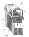
- Fig. 2 is a perspective, fragmentary view of a heat exchanger, and more particularly a heat exchanger, which may be used as an air-to-air aftercooler, such as the aftercooler 10 of Fig. 1.
- This type of heat exchanger is described in detail in Figs US Pat. No. 6,729,388 B2 owned by Behr GmbH & Co. of Stuttgart, Germany, and which is hereby incorporated by reference in its entirety.
- the intercooler 10 has a fin tube block 12 connected to a charge air inlet chamber 14 and a charge air outlet chamber (not shown).
- the lamellae tube block 12 has flat tubes 16 between which lamellae in the form of meshed lamellae or corrugated fins are arranged.
- the fins 18 are soldered to the flat tubes 16.
- the charge air exhaust gas fuel mixture 6 (FIG. 1) flows from the charge air intake chamber 14 through the flat tubes 16 into the charge air discharge chamber. Perpendicular to this charge air flow, the fins 18 are subjected to the action of ambient air 20. Since the charge air has a much higher temperature than the ambient air 20, there is a heat transfer from the charge air to the ambient air 20.
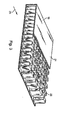
- the reference numeral 22 denotes inner fin elements, which are also known as “turbulators”, which are arranged in the flat tubes 16 and soldered to the same.
- the turbulators assist in improved mixing of charge air in the flat tubes 16.
- FIG. 3 is a cutaway view of a flat tube 16, the end wall 24 of which is also shown in FIG. In Fig. 3, the orientation and arrangement of the turbulator elements 22 can be seen better.
- the charge air-exhaust mixture 6 generally flows through the flat tube 16 in the direction indicated by the arrow 26.
- an improved mixing of the hot core flow with the boundary layer flow is achieved.
- the heat of the core flow is no longer guided by the inner fin element and the boundary layer flow through the wall. That is, the surface layer flow is purposely broken and mixed. This results in an increase in the heat transfer capacity of the intercooler 10th
- FIGS. 2 and 3 illustrate a particularly advantageous type of turbulator, one skilled in the art will understand that different structures and arrangements of structures can be used as turbulator elements and are still within the scope of the invention.
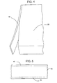
- FIG. 4 illustrates an aluminum clad 32 attached to an aluminum core 30.
- the plating is usually an Al-Si alloy having a lower melting point compared to the core.
- the plating becomes a sacrificial layer useful for resisting corrosion of the core elements. This sacrificial layer is also known as a "brown ribbon" layer.
- FIG. A sectional view of a brazing sheet suitable for use with corrosion resistant air-to-air heat exchanger components is shown in FIG.
- This figure shows platings 42 and 44 which have been rolled onto a core 40.
- the cladding is made of AA 4045 alloy and the core is made of AA 3003 alloy or the like.
- Another suitable plating alloy for CAB is AA 4343 or 4047.
- AA 4004, 4104, or 4047 plating may be used in vacuum brazing (VB) processes.
- the thickness of the platings 42 and 44 is not more than 15% of the core thickness.
- a suitable composition for producing such a "brown tape" sacrificial layer may be used to form end walls 24 of flat tubes 16 of the heat exchanger ( Figure 2), as well as turbulator elements 22 of the tubes 16th
- FIG. 6 illustrates brown belt turbulators 22 in a tube 16, particularly between end walls 24.
- each end wall 24 of a flat tube has a core 50, 60 and claddings 52, 54 and 62, 64 on both sides, whereby the brown band sacrificial layer is formed after soldering.
- both the tubes and the turbulator elements are formed of the same brown ribbon material, thereby promoting a maximum anticorrosive effect.
- FIG. 7A is an enlarged view of turbulator element 22 and end wall 24 prior to a soldering operation.
- FIG. Plates 56a and 58a surround a core 55a of a turbulator element 22.
- Comparable plating 62a and 64a surround a core 60a of an end wall 24. At this point in the process of fabricating the heat exchanger, the "brown tape" sacrificial layer has not yet been formed.
- FIG. 7B in turn illustrates an enlarged view of the same area shown in FIG. 7A, but after the turbulator element 22 of the present invention has been soldered to the end wall 24 of a flat tube 16.
- the turbulator 22 itself includes a core 55 and sacrificial layers 56, 58.
- the end wall 24 of the flat tube 16 has a core 60 and sacrificial layers 62, 64.
- the soldering process converts the surface of the turbulator core by silicon diffusion from the plating layer into the core, ie, 56a, 58a in sacrificial layers 56 and 58. The same applies to the cladding on the end walls.
- the alloy used to form the turbulator elements is identical to the alloy used to form the tube wall, although one skilled in the art will recognize that this is not always necessary.
- the material used to form the turbulator elements may be "down-measured” from the material used to form the tube elements.
- the chemical interaction of the various layers during a process of inert gas soldering (CAB) and / or Vacuum soldering (VB) resulted in a "brown tape" sacrificial layer formed on the entire turbulator and pipe assembly.
- fillet welds 70, 72 provide the connection between the turbulator 22 and the tube 16, with the fillet welds 70, 72 in turn having a "brown band” sacrificial layer.
- Figure 8 illustrates a prior art turbulator / tube connection.
- neither the turbulator nor the tube has a brown band "Sacrifice layer on. Due to the absence of such a layer, this turbulator element in conjunction with recirculated engine gas will not have the same anticorrosive effects as the more protected embodiment of Fig. 7.
- the fillet welds 70, 72 used in the embodiment of Figs 7 are greater than the fillet welds 82, 84 of the embodiment of FIG. 8.
- the sacrificial layer in the preferred embodiment is independent of the shape of the turbulator elements.
Abstract
Description
Die vorliegende Erfindung betrifft einen Wärmetauscher im Allgemeinen, und einen Turbulator für einen Ladeluftkühler im Besonderen, der gegenüber Korrosion beständig ist, und ein Verfahren zur effizienten Herstellung eines solchen Wärmetauschers. Ein gemäß der vorliegenden Erfindung hergestellter Wärmetauscher mit einem Turbulator kann besonders vorteilhaft für die Verwendung in Fahrzeugen sein, bei denen Abgas mit niedrigem Druck dem Ladeluftkühler zugeführt wird.The present invention relates to a heat exchanger in general, and to a charge air cooler turbulator in particular which is resistant to corrosion, and to a method for efficiently producing such a heat exchanger. A heat exchanger with a turbulator made in accordance with the present invention may be particularly advantageous for use in vehicles where low pressure exhaust gas is supplied to the charge air cooler.
Auto- und andere Kraftfahrzeughersteller sehen sich mit einer beständig wachsenden Nachfrage konfrontiert, saubere und sparsamere Fahrzeuge herzustellen. Diese Hersteller müssen Verbrennungsmotoren herstellen, die Leistungsanforderungen entsprechen und gleichzeitig den wachsenden E-missionserfordernissen verschiedener staatlicher Standards und Industriestandards genügen.Automobile and other motor vehicle manufacturers face a constantly growing demand to produce cleaner and more economical vehicles. These manufacturers need to produce internal combustion engines that meet the performance requirements while meeting the growing e-mission needs various government standards and industry standards.
Motortechnologien, die diese Anforderung angehen, beinhalten elektronische Motorsteuerungen und damit in Zusammenhang stehende Sensoren, Turbolader und Abgas-/Motorgasrückführungs- ("EGR")-Verfahren. Wo Ladelufttechnologien verwendet werden, z.B. die Verwendung eines Turboladers, wurde schon lange erkannt, dass ein richtig ausgeführter Wärmetauscher - auch als ein Nach- oder Zwischenkühler bekannt - die Motoreffizienz erhöhen kann, während er gleichzeitig unerwünschte Emissionen verringert.Engine technologies that address this requirement include electronic engine controls and related sensors, turbochargers, and exhaust gas / gas recirculation ("EGR") processes. Where charge air technologies are used, e.g. Using a turbocharger, it has long been recognized that a properly designed heat exchanger - also known as a post or intercooler - can increase engine efficiency while reducing unwanted emissions.
Das Verfahren der Aufladung von Luft in einem Turbolader resultiert in einem Anstieg der Temperatur der Ladeluft. Nachkühler sind Wärmetauscher, üblicherweise Luft-Luft-Wärmetauscher, die Umgebungs- oder Außenluft für die Kühlung der Motoransaugluft verwenden, nachdem sie eine Ladevorrichtung passiert hat und bevor sie in eine Verbrennungskammer des Motors eintritt. Kältere Treibstoff/Luft-Gemische brennen effizienter mit wesentlich verringerten Emissionen als ungekühlte Ladeluft. Ein geeignetes Aufladen der Luft, wenn in Verbindung mit Luft-Luft-Kühlvorrichtungen, kann eine Motorleistungsdichte wesentlich erhöhen mit geringer oder ohne einer Vergrößerung seiner physikalischen Abmessungen oder Verringerung seiner erwarteten Standzeit vor einer Wartung.The process of supercharging air in a turbocharger results in a rise in the temperature of the charge air. Aftercoolers are heat exchangers, typically air-to-air heat exchangers, which use ambient or outside air to cool the engine intake air after it has passed a loader and before entering a combustion chamber of the engine. Cooler fuel / air mixtures burn more efficiently with significantly lower emissions than uncooled charge air. Proper charging of air, when used in conjunction with air-to-air cooling devices, can significantly increase engine power density with little or no increase in its physical dimensions or reduction in its expected life before maintenance.
Abgasrückführung ("EGR") ist eine ergänzende Technologie zur Verringerung schädlicher Emissionen, insbesondere bei Dieselmotoren. Dieselmotoren verdichten große Volumen von Luft, die - wenn gemischt mit Treibstoff und entzündet - verbrennt, um Energie zu erzeugen. Wenn ein Kohlenwasserstoffbrennstoff brennt, wird der Brennstoff in Kohlendioxid und Wasserdampf umgewandelt. Zusätzliche Nebenprodukte der Verbrennung umfassen Säuren, Partikelverunreinigungen, wie auch Oxide von Stickstoff (NOx). Bei einem EGR-System werden einige der Verbrennungsgase für eine zusätzliche Verbrennung zum Saugrohr zurückgeführt, um die Menge an Treibstoff zu erhöhen, die verbrannt wurde, bevor sie in die Atmosphäre gelangen. EGR-Systeme führen üblicherweise auch zu einer niedrigeren Verbrennungstemperatur und verringerten NOx-Abgasnebenprodukten als Systeme ohne Abgasrückführung.Exhaust gas recirculation ("EGR") is a complementary technology for reducing harmful emissions, especially in diesel engines. Diesel engines compress large volumes of air that, when mixed with fuel and ignited, burns to produce energy. When a hydrocarbon fuel burns, the fuel is converted to carbon dioxide and water vapor. Additional byproducts of combustion include acids, particulate contaminants, as well as oxides of nitrogen (NOx). In an EGR system, some of the combustion gases are for an additional Combustion is returned to the intake manifold to increase the amount of fuel that was burned before it enters the atmosphere. EGR systems also typically result in lower combustion temperatures and reduced NOx exhaust by-products than systems without exhaust gas recirculation.
Bei vielen EGR-Systemen wird Abgas direkt in das Saugrohr eines Motors zurückgeführt. Es ist jedoch möglich, das Abgas auch durch einen Ladeluft-Nachkühler oder -Zwischenkühler (der Einfachheit halber bezieht dieses Patent sich auf alle derartigen Wärmetauscher als "Nachkühler") zu führen, um das Abgas weiter abzukühlen, bevor es in das Motorsaugrohr gelangt. Die meisten Nachkühler sind jedoch so ausgebildet, dass sie nur Luft (kein Abgas) durch die Kühlrohre des Wärmetauschers lassen. Obwohl Luft üblicherweise keine Bestandteile umfasst, welche die Bauteile eines Nachkühlers angreifen, hat dies rückgeführtes Motorgas. Abgas umfasst - neben anderen Dingen - schädliche Säurekondensate. Diese korrosiven Säurekondensate, wie Schwefelsäure, Essigsäure und Ameisensäure, erhöhen die Wahrscheinlichkeit von Korrosion im Nachkühler.In many EGR systems, exhaust gas is returned directly to the intake manifold of an engine. However, it is also possible to pass the exhaust gas through a charge air aftercooler or intermediate cooler (for simplicity, this patent refers to all such heat exchangers as "aftercoolers") to further cool the exhaust gas before it enters the engine intake manifold. However, most aftercoolers are designed to only let air (no exhaust) through the heat exchanger's cooling tubes. Although air typically does not include components which attack the components of an aftercooler, this has recirculated engine gas. Exhaust gas includes - among other things - harmful acid condensates. These corrosive acid condensates, such as sulfuric acid, acetic acid and formic acid, increase the likelihood of corrosion in the aftercooler.
Es besteht daher ein Bedarf an einem Nachkühler, der die korrosiven Effekte der Abgaskondensate widerstehen kann. Problematische Elemente im Nachkühler und insbesondere "Turbulator"-Elemente der Kühlrohre des Wärmetauschers müssen korrosionsbeständig gemacht werden. Obwohl korrosionsbeständige Legierungen für Wärmetauscher bekannt sind, wie diejenigen, die im
Die Erfindung betrifft im Allgemeinen einen Wärmetauscher für ein Kraftfahrzeug, wie einen Nachkühler, der Turbulatorelemente in den Wärmetauscher-Kühlrohren enthält. Die Turbulatorelemente weisen einen Kern und einer Plattierung, die, wenn in einem Lötofen verlötet, ein "braunes Band" oder eine Opferdiffusionsschicht bildet, die Korrosion auf ausgezeichnete Weise widersteht, verglichen mit zuvor bekannten Turbulatorelementen. Die Plattierung ist üblicherweise eine Al-Si-Legierung, die einen geringeren Schmelzpunkt als der Kern hat. Wie auf diesem Gebiet bekannt ist, diffundiert während des Lötvorgangs Silikon von der Plattierung in den Kern, wodurch eine Opferschicht gebildet wird, die nützlich für das Widerstehen von Korrosion der Kernelemente ist. Diese Opferschicht ist auch auf diesem Gebiet als eine "braune Band-"Schicht bekannt.The invention generally relates to a heat exchanger for a motor vehicle, such as an aftercooler, which includes turbulator elements in the heat exchanger cooling tubes. The turbulator elements have a core and plating which, when brazed in a brazing furnace, forms a "brown band" or sacrificial diffusion layer which resists corrosion in an excellent manner compared to previously known turbulator elements. The cladding is usually an Al-Si alloy having a lower melting point than the core. As is known in the art, during the soldering process, silicon diffuses from the plating into the core, forming a sacrificial layer useful for resisting corrosion of the core elements. This sacrificial layer is also known in the art as a "brown band" layer.
Die Plattierung, besonders bevorzugt die doppelseitige Plattierung, weist vorzugsweise eine Aluminiumlegierung der 4000-er Reihe oder einer hiervon abgewandelten Zusammensetzung auf. Insbesondere bevorzugt sind Aluminiumlegierungen der Reihen 4004, 4045, 4047, 4104, 4545 oder Abwandlungen hiervon.The plating, more preferably the double-sided plating, preferably comprises an aluminum alloy of the 4000 series or a modified composition thereof. Particularly preferred are aluminum alloys of the series 4004, 4045, 4047, 4104, 4545 or modifications thereof.
Gemäß einem besonders bevorzugten Ausführungsbeispiel sind die Turbulatorelemente aus einem modifizierten AA3003 Aluminiumkern oder einer ähnlichen Legierung (die "AA" Kennzeichnung betrifft die Aluminium Association Inc., welche die Zusammensetzung von Standardaluminiumlegierungen festlegt), die ihrerseits mit einer relativ dünnen Schicht (z.B. 5% der Kerngröße) mit AA4045 Aluminium auf beiden Seiten beschichtet ist. Die Turbulatorelemente werden dann zu einem Rohrbauteil in einem Lötofen gelötet. Gemäß einem besonders bevorzugten Ausführungsbeispiel werden die Turbulatorelemente mittels Gewichtsreduktion aus den Rohrbauteilen gebildet. Alternativ können die Turbulatorelemente die gleiche oder im Wesentlichen die gleiche chemische Zusammensetzung aufweisen, wie sie für das Rohr verwendet wurde, so dass ein geeignetes braunes Band ausgebildet werden kann.According to a particularly preferred embodiment, the turbulator elements are made of a modified AA3003 aluminum core or similar alloy (the "AA" designation refers to Aluminum Association Inc., which defines the composition of standard aluminum alloys), which in turn is coated with a relatively thin layer (
Die Turbulatorelemente weisen bevorzugt eine im Wesentlichen U-förmige Gestalt auf. Alternativ sind Sinusformen, aufgeschnitten und versetzte Formen oder trapezförmige oder rechteckige Formen möglich.The turbulator elements preferably have a substantially U-shaped form. Alternatively, sinusoids, sliced and staggered shapes or trapezoidal or rectangular shapes are possible.
Die Dicke der Turbulatorelemente liegt vorzugsweise im Bereich von 0,1 bis 1,0 mm.The thickness of the turbulator elements is preferably in the range of 0.1 to 1.0 mm.
Die Plattierung ist besonders bevorzugt doppelseitig aufgebracht.The plating is particularly preferably applied to both sides.
Weitere Gegenstände, Merkmale und Vorteile der Erfindung werden aus der detaillierten Beschreibung der bevorzugten Ausführungsbeispiele, die folgen, ersichtlich, wenn sie in Verbindung mit den angehängten Figuren der Zeichnung betrachtet werden.Other objects, features and advantages of the invention will be apparent from the detailed description of the preferred embodiments which follow, when taken in conjunction with the annexed figures of the drawing.
Beispielhafte Ausführungsbeispiele der Erfindung werden im Folgenden unter Bezugnahme auf die Zeichnung angeführt, bei denen:
- Fig. 1 eine Zeichnung ist, die schematisch den Luftstrom in einem Motor darstellt, der dazu bestimmt ist, EGR-Abgas durch einen Nachkühler zu führen;
- Fig. 2 eine perspektivische Ansicht eines beispielhaften Nachkühler-Wärmetauschers ist, der Turbulatorelemente umfasst;
- Fig. 3 eine vergrößerte, perspektivische Ansicht eines Kühlrohres in einem Nachkühler-Wärmetauscher ist, welche die Turbulatorelemente weiter veranschaulicht;
- Fig. 4 eine perspektivische Zeichnung, welche den Kern und die Plattierung auf einer Aluminiumlegierung veranschaulicht, die nützlich bei der Bildung von Turbulatorelementen gemäß der vorliegenden Erfindung ist;
- Fig. 5 eine Schnittdarstelllung der Aluminiumlegierung von Fig. 4;
- Fig. 6 eine Schnittdarstellung eines Kühlrohrs in einem Wärmetauscher, der gemäß der vorliegenden Erfindung hergestellt ist;
- Fig. 7A eine vergrößerte Darstellung des Bereichs, in dem ein Turbulatorelement gemäß der vorliegenden Erfindung neben der Seitenwand eines Kühlrohrs vor dem Löten angeordnet ist, und
- Fig. 7B eine vergrößerte Darstellung des Bereichs, in dem ein Turbulatorelement gemäß der vorliegenden Erfindung an die Seitenwand eines Kühlrohrs angelötet wird; und
- Fig. 8 zur Verfügung gestellt wird aus Vergleichszwecken und eine vergrößerte Darstellung des Bereichs, in dem ein Turbulatorelement gemäß dem Stand der Technik an die Seitenwand eines Kühlrohrs angelötet wird.
- Fig. 1 is a drawing which schematically illustrates the air flow in an engine designed to pass EGR exhaust gas through an aftercooler;
- FIG. 2 is a perspective view of an exemplary aftercooler heat exchanger including turbulator elements; FIG.
- 3 is an enlarged perspective view of a cooling tube in an aftercooler heat exchanger further illustrating the turbulator elements;
- Fig. 4 is a perspective drawing illustrating the core and cladding on an aluminum alloy useful in the formation of turbulator elements according to the present invention;
- Fig. 5 is a sectional view of the aluminum alloy of Fig. 4;
- Fig. 6 is a sectional view of a cooling pipe in a heat exchanger made in accordance with the present invention;
- 7A is an enlarged view of the area where a turbulator element according to the present invention is disposed adjacent to the side wall of a cooling tube before soldering, and
- Fig. 7B is an enlarged view of the area in which a turbulator element according to the present invention is soldered to the side wall of a cooling tube; and
- Fig. 8 is provided for comparison purposes and an enlarged view of the area in which a turbulator element according to the prior art is soldered to the side wall of a cooling tube.
Ein mögliches Beispiel für die Anwendung der vorliegenden Erfindung beinhaltet ein EGR-Turbolader-Dieselmotorsystem. Fig. 1 veranschaulicht schematisch die "Leitungen" eines solchen Systems. Der Dieselmotor selbst wird schematisch durch das Bezugszeichen 8 wiedergegeben. Bei diesem System tritt Umgebungsluft 1 in einen Turbolader 2 ein, der mittels Abgas 7, das den Dieselmotor 8 verlässt, angetrieben wird. Abgas 7, nach dem Antreiben der Turbine des Turboladers 2 wird nachfolgend an die Atmosphäre 9 abgegeben. Ladeluft 3, die den Turbolader 2 verlässt, wird danach mit einem anderen Strom von (Niederdruck-)Abgas 5 vermischt. Obwohl dieses Mischen auf verschiedene Arten erfolgen kann, ist es in Fig. 1 als in einem Mischelement 4 erfolgend verdeutlicht, das ein geeignetes Ventil oder Sammelrohr sein kann.One possible example of the application of the present invention includes an EGR turbocharged diesel engine system. Fig. 1 schematically illustrates the "conduits" of such a system. The diesel engine itself is represented schematically by the
Bei dieser exemplarischen Umgebung tritt, nachdem die Ladeluft 3 mit Abgas 5 gemischt wird, die Mischung 6 in einen Luft-Luft-Nachkühler 10 ein. Die Luftmischung 6 passiert durch Kühlrohre (im Folgenden beschrieben) im Nachkühler 10, die in Fluidkontakt mit einem erzwungenen Umgebungsluftstrom (nicht dargestellt) sind. Das Zusammenwirken von Umgebungsluft mit Kühlrohren bewirkt, dass die Ladeluft-Abgasmischung 6 abkühlt. Die nun relativ kühlere Ladeluft-Abgasmischung 11 dem Saugrohr des Dieselmotors 8 zugeführt wird, wo sie nachfolgend verbrannt wird.In this exemplary environment, after the charge air 3 is mixed with
Das Abgas 5, das sich mit der Ladeluft 3 vermischt, hat einen relativ geringen Druck verglichen mit dem Abgas 7, das verwendet wird, um die Turbine des Turboladers 2 anzutreiben. Das Verfahren des Sammelns von Abgas 5, um es zurück in das Saugrohr eines Dieselmotors zu leiten, ist einem Fachmann bekannt und wird beispielsweise im
Fig. 2 ist eine perspektivische, ausschnittsweise Ansicht eines Wärmetauschers, und insbesondere eines Wärmetauschers, der verwendet werden kann als ein Luft-Luft-Nachkühler, so wie der Nachkühler 10 der Fig. 1. Diese Art von Wärmetauscher ist im Detail im
Der Ladeluftkühler 10 weist einen Lamellen-Rohrblock 12 auf, der mit einer Ladeluft-Einlasskammer 14 und einer Ladeluft-Auslasskammer (nicht dargestellt) verbunden ist. Der Lamellen-Rohrblock 12 weist Flachrohre 16 zwischen denen Lamellen in Form von mit einem Netz versehenen Lamellen oder gewellten Lamellen angeordnet sind. Die Lamellen 18 sind mit den Flachrohren 16 verlötet. Die Ladeluft-Abgas-Treibstoff-Mischung 6 (Fig. 1) strömt von der Ladeluft-Einlasskammer 14 durch die Flachrohre 16 in die Ladeluft-Auslasskammer. Senkrecht zu dieser Ladeluftströmung werden die Lamellen 18 der Einwirkung von Umgebungsluft 20 unterworfen. Da die Ladeluft eine wesentlich höhere Temperatur als die Umgebungsluft 20 hat, erfolgt ein Wärmeübergang von der Ladeluft zur Umgebungsluft 20.The
Das Bezugszeichen 22 bezeichnet innere Lamellenelemente, die auch als "Turbulatoren" bekannt sind, welche in den Flachrohren 16 angeordnet und mit denselben verlötet sind. Die Turbulatoren unterstützen ein verbessertes Mischen von Ladeluft in den Flachrohren 16. Fig. 3 ist eine aufgeschnittene Ansicht eines Flachrohrs 16, dessen Endwand 24 auch in Fig. 2 dargestellt ist. In Fig. 3 ist die Ausrichtung und Anordnung der Turbulatorelemente 22 besser ersichtlich. Die Ladeluft-Abgas-Mischung 6 strömt im Allgemeinen durch das Flachrohr 16 in dir Richtung, die durch den Pfeil 26 angezeigt ist. Mittels der Turbulatoren 22 wird ein verbessertes Mischen der heißen Kernströmung mit der Randschichtströmung erreicht. Somit werden die Wärme der Kernströmung nicht länger durch das innere Lamellenelement und die Randschichtströmung durch die Wand geführt. Das heißt, die Randschichtströmung wird absichtlich aufgebrochen und vermischt. Dies resultiert in einem Anstieg der Wärmeübergangsleistung des Ladeluftkühlers 10.The
Obwohl die Figuren 2 und 3 einen besonders vorteilhaften Typ eines Turbulators darstellen, wird ein Fachmann verstehen, dass unterschiedliche Strukturen und Anordnungen von Strukturen als Turbulatorelemente verwendet werden können und noch im Umfang der Erfindung liegen.Although Figures 2 and 3 illustrate a particularly advantageous type of turbulator, one skilled in the art will understand that different structures and arrangements of structures can be used as turbulator elements and are still within the scope of the invention.
Fig. 4 stellt eine Aluminiumplattierung 32 dar, die an einem Aluminiumkern 30 angebracht ist. Wie in dem oben genannten
Eine geschnittene Ansicht eines Lötblechs, dass geeignet für die Verwendung für korrosionsbeständigen Luft-Luft-Wärmetauscherbautelle ist, ist in Fig. 5 dargestellt. Diese Figur zeigt Plattierungen 42 und 44, die auf einen Kern 40 gerollt wurden. Bei einem besonders bevorzugten Ausführungsbeispiel der Erfindung besteht die Plattierung aus einer AA 4045 Legierung und der Kern besteht aus einer AA 3003 Legierung o.ä. Eine andere geeignete Plattierungslegierung für Lötverfahren unter Schutzgas (CAB) umschließt AA 4343 oder 4047. Zusätzlich können bei Vakuumlötverfahren (VB) AA 4004, 4104 oder 4047 Plattierungen verwendet werden. Gemäß einem besonders bevorzugten Ausführungsbeispiel beträgt die Dicke der Plattierungen 42 und 44 nicht mehr als 15% der Kerndicke. Auf Grund der Diffusion des Siliziums während des Lötvorgangs haben die Anmelder empirisch bestimmt, dass eine Plattierung von etwa 5% der Dicke des Kerns 40 in einer optimalen Opferschicht resultieren wird. Eine geeignete Zusammensetzung zum Erzeugen eines derartigen "braunen Bandes" Opferschicht, wie in der gerollten Anordnung von Fig. 5, kann verwendet werden, um Endwände 24 von Flachrohren 16 des Wärmetauschers (Fig. 2) zu bilden, wie auch als Turbulatorelemente 22 der Rohre 16.A sectional view of a brazing sheet suitable for use with corrosion resistant air-to-air heat exchanger components is shown in FIG. This figure shows
Fig. 6 stellt Turbulatoren 22 mit braunem Band in einem Rohr 16 dar, insbesondere zwischen Endwänden 24. Bei dem bevorzugten Ausführungsbeispiel der Erfindung weist jede Endwand 24 eines Flachrohres einen Kern 50, 60 und auf beiden Seiten Plattierungen 52, 54 bzw. 62, 64 auf, wodurch die braune Band Opferschicht nach dem Löten gebildet wird. Bei diesem Ausführungsbeispiel sind sowohl die Rohre als auch die Turbulatorelemene aus dem selben braunen Bandmaterial ausgebildet, wodurch ein maximaler antikorrosiver Effekt unterstützt wird.FIG. 6 illustrates brown belt turbulators 22 in a
Fig. 7A ist eine vergrößerte Ansicht des Turbulatorelements 22 und der Endwand 24 vor einem Lötvorgang. Plattierungen 56a und 58a umgeben einen Kern 55a eines Turbulatorelements 22. Vergleichbare Plattierungen 62a und 64a umgeben einen Kern 60a einer Endwand 24. Zu diesem Zeitpunkt des Herstellungsverfahrens des Wärmetauschers wurde die "braune Band"-Opferschicht noch nicht erzeugt.FIG. 7A is an enlarged view of
Fig. 7B ihrerseits stellt eine vergrößerte Ansicht des gleichen Bereichs, der in Fig. 7A dargestellt ist, dar, aber nachdem das Turbulatorelement 22 der vorliegenden Erfindung an die Endwand 24 eines Flachrohrs 16 angelötet wurde. Wie aus dieser Figur offensichtlich ist, umfasst der Turbulator 22 selbst einen Kern 55 und Opferschichten 56, 58. Vergleichbar weist die Endwand 24 des Flachrohrs 16 einen Kern 60 und Opferschichten 62,64 auf. Der Lötvorgang wandelt die Oberfläche des Turbulatorkems mittels Siliziumdiffusion von der Plattierungsschicht in den Kern, d.h. 56a, 58a in Opferschichten 56 und 58, um. Das Gleiche trifft für die Plattierung an den Endwänden zu. Bei diesem besonders bevorzugten Ausführungsbeispiel ist die Legierung, die verwendet wird, um die Turbulatorelemente zu bilden, identisch der Legierung, die verwendet wird, um die Rohrwand zu bilden, obwohl ein Fachmann erkennen wird, dass dies nicht immer erforderlich ist. In diesem Hinblick kann das Material, das verwendet wird, um die Turbulatorelemente zu bilden, "heruntergemessen" von dem Material sein, das verwendet wird, um die Rohrelemente zu bilden. Das chemische Zusammenspiel der verschiedenen Schichten während eines Vorgangs eines Schutzgaslötens (CAB) und/oder eines Vakuumlötens (VB) resultierte in einer "braunen Band"-Opferschicht, die an der gesamten Turbulator- und Rohranordnung ausgebildet wurde. Wie in Fig. 7B dargestellt, stellen Kehlnähte 70, 72 die Verbindung zwischen dem Turbulator 22 und dem Rohr 16 dar, wobei die Kehlnähte 70, 72 ihrerseits eine "braune Band"-Opferschicht aufweisen.FIG. 7B in turn illustrates an enlarged view of the same area shown in FIG. 7A, but after the
Im Gegensatz zu der Struktur, die in Fig. 7 dargestellt ist, stellt Fig. 8 eine Turbulator/Rohr-Verbindung gemäß dem Stand der Technik dar. Bei dieser Ausführungsform gemäß dem Stand der Technik weist weder der Turbulator noch das Rohr eine "braune Band"-Opferschicht auf. Auf Grund des Fehlens einer derartigen Schicht, wird dieses Turbulatorelement in Verbindung mit rückgeführtem Motorgas nicht die selben antikorrosiven Wirkungen haben als das geschütztere Ausführungsbeispiel von Fig. 7. Zusätzlich wurde mittels experimenteller Methoden herausgefunden, dass die Kehlnähte 70, 72, die bei dem Ausführungsbeispiel von Fig. 7 erzeugt wurden, größer als die Kehlnähte 82, 84 der Ausführungsform von Fig. 8 sind. Es sei jedoch angemerkt, dass die Opferschicht bei dem bevorzugten Ausführungsbeispiel unabhängig von der Gestalt der Turbulatorelemente ausgebildet ist.In contrast to the structure shown in Figure 7, Figure 8 illustrates a prior art turbulator / tube connection. In this prior art embodiment, neither the turbulator nor the tube has a brown band "Sacrifice layer on. Due to the absence of such a layer, this turbulator element in conjunction with recirculated engine gas will not have the same anticorrosive effects as the more protected embodiment of Fig. 7. In addition, it has been found by experimental methods that the fillet welds 70, 72 used in the embodiment of Figs 7 are greater than the fillet welds 82, 84 of the embodiment of FIG. 8. It should be noted, however, that the sacrificial layer in the preferred embodiment is independent of the shape of the turbulator elements.
Während diese Erfindung mit einer Betonung auf spezielle Ausführungsbeispiele beschrieben worden ist, sollte es verstanden werden, dass die vorstehende Beschreibung auf die gegenwärtig betrachteten, besten Arten zum Anwenden der Erfindung geschränkt wurde. Zum Beispiel die genaue Form der Turbulatoren und/oder der Flachrohre kann in Übereinstimmung der Erfindung abgeändert werden. Es wird offensichtlich sein, dass weitere Abwandlungen der Erfindung möglich sind, und dass einige oder alle Vorteile der Erfindung erreicht werden können. Es ist auch nicht erforderlich, dass die Erfindung alle der zuvor beschriebenen Merkmale und Aspekte oder Kombinationen derselben benötigt. In vielen Fällen sind bestimmte Merkmale und Aspekte nicht wesentlich für die Durchführung anderer Merkmale und Aspekte. Die Erfindung sollte nur durch die angehängten Ansprüche und Äquivalente derselben beschränkt sein, da die Ansprüche dafür gedacht sind, die anderen Abwandlungen und Modifikationen abzudecken, selbst wenn sie nicht in deren wörtlichen Umfang liegen.While this invention has been described with an emphasis on specific embodiments, it should be understood that the foregoing description has been limited to the best modes contemplated for practicing the invention. For example, the exact shape of the turbulators and / or the flat tubes may be modified in accordance with the invention. It will be apparent that further modifications of the invention are possible, and that some or all of the advantages of the invention may be obtained. It is also not necessary that the invention require all of the features and aspects or combinations thereof described above. In many cases, certain features and aspects are not essential to the performance of other features and aspects. The invention should only be pointed out by the appended claims and equivalents of the same, as the claims are intended to cover the other modifications and alterations, even if not to the literal extent thereof.
Claims (17)
Applications Claiming Priority (1)
| Application Number | Priority Date | Filing Date | Title |
|---|---|---|---|
| US11/222,262 US20070051503A1 (en) | 2005-09-08 | 2005-09-08 | Corrosion resistant charge air cooler and method of making same |
Publications (1)
| Publication Number | Publication Date |
|---|---|
| EP1762810A2 true EP1762810A2 (en) | 2007-03-14 |
Family
ID=37488054
Family Applications (1)
| Application Number | Title | Priority Date | Filing Date |
|---|---|---|---|
| EP06018881A Withdrawn EP1762810A2 (en) | 2005-09-08 | 2006-09-08 | Corrosion resistant charged air cooler and process for making same |
Country Status (2)
| Country | Link |
|---|---|
| US (1) | US20070051503A1 (en) |
| EP (1) | EP1762810A2 (en) |
Cited By (4)
| Publication number | Priority date | Publication date | Assignee | Title |
|---|---|---|---|---|
| DE102008059450A1 (en) | 2008-11-28 | 2010-06-02 | Behr Gmbh & Co. Kg | Aluminum strip, soldering component, manufacturing method and heat exchanger and use |
| WO2012160267A1 (en) | 2011-05-20 | 2012-11-29 | Constellium France | Alloys for a heat exchanger tube having an inner protective cladding and brazed disrupter |
| CN104612813A (en) * | 2015-03-09 | 2015-05-13 | 北京动力机械研究所 | High-heat-flux-density compact type triangular rib intercooler |
| WO2017032567A1 (en) * | 2015-08-25 | 2017-03-02 | Valeo Systemes Thermiques | Heat exchanger |
Families Citing this family (7)
| Publication number | Priority date | Publication date | Assignee | Title |
|---|---|---|---|---|
| JP4881583B2 (en) * | 2005-06-27 | 2012-02-22 | 株式会社豊田自動織機 | Power module heat sink |
| CN102555335A (en) * | 2012-01-17 | 2012-07-11 | 无锡冠云铝业有限公司 | Aluminum alloy composite material for condenser and preparation method thereof |
| CN102734986A (en) * | 2012-06-28 | 2012-10-17 | 无锡冠云铝业有限公司 | Aluminum and zirconium laminated foil for condenser of automobile |
| FR3018213B1 (en) * | 2014-03-06 | 2016-10-21 | Constellium France | MULTI-PLASTER SOLDERING SHEET |
| US9689353B2 (en) * | 2015-08-27 | 2017-06-27 | GM Global Technology Operations LLC | Charge air cooler device |
| CN105317527A (en) * | 2015-11-26 | 2016-02-10 | 南充元顺机械集团有限公司 | Internal turbulent type intercooler |
| KR102371237B1 (en) * | 2017-05-11 | 2022-03-04 | 현대자동차 주식회사 | Water-cooled egr cooler, and the manufacutring method thereof |
Citations (3)
| Publication number | Priority date | Publication date | Assignee | Title |
|---|---|---|---|---|
| US5802846A (en) | 1997-03-31 | 1998-09-08 | Caterpillar Inc. | Exhaust gas recirculation system for an internal combustion engine |
| US6729388B2 (en) | 2000-01-28 | 2004-05-04 | Behr Gmbh & Co. | Charge air cooler, especially for motor vehicles |
| US6921584B2 (en) | 2001-05-03 | 2005-07-26 | Norsk Hydro Asa | Brazing sheet |
Family Cites Families (17)
| Publication number | Priority date | Publication date | Assignee | Title |
|---|---|---|---|---|
| US4735867A (en) * | 1985-12-06 | 1988-04-05 | Kaiser Aluminum & Chemical Corporation | Corrosion resistant aluminum core alloy |
| US5295302A (en) * | 1991-10-29 | 1994-03-22 | Calsonic Corporation | Method of manufacturing an aluminum heat exchanger |
| US5275233A (en) * | 1993-01-25 | 1994-01-04 | Ingersoll-Rand Company | Apparatus for removing moisture from a hot compressed gas |
| US5511610A (en) * | 1994-03-15 | 1996-04-30 | Behr Heat Transfer Systems | Off-set louvered heat exchanger fin and method for making same |
| US5555930A (en) * | 1994-06-24 | 1996-09-17 | Behr Heat Transfer, Inc. | Heat exchanger assembly with structural side passageways |
| US5447192A (en) * | 1994-07-12 | 1995-09-05 | Behr Heat Transfer Systems, Inc. | Heat exchanger assembly with reinforcement and method for making same |
| US5482114A (en) * | 1995-02-13 | 1996-01-09 | Behr Heat Transfer Systems, Inc. | Charged air cooler mounting bars |
| US5476140A (en) * | 1995-02-21 | 1995-12-19 | Behr Heat Transfer Systems, Inc. | Alternately staggered louvered heat exchanger fin |
| US5894054A (en) * | 1997-01-09 | 1999-04-13 | Ford Motor Company | Aluminum components coated with zinc-antimony alloy for manufacturing assemblies by CAB brazing |
| JP2002525753A (en) * | 1998-09-22 | 2002-08-13 | サイエンス アプリケーションズ インターナショナル コーポレイション | Dynamic collaborative environment set by user |
| US6332495B1 (en) * | 1999-06-02 | 2001-12-25 | Long Manufacturing Ltd. | Clip on manifold heat exchanger |
| US6329075B1 (en) * | 2000-02-03 | 2001-12-11 | Reycan, L.P. | Electrical conductivity and high strength aluminum alloy composite material and methods of manufacturing and use |
| US20040205065A1 (en) * | 2000-02-10 | 2004-10-14 | Petras Gregory J. | System for creating and maintaining a database of information utilizing user opinions |
| DE10011954A1 (en) * | 2000-03-11 | 2001-09-13 | Modine Mfg Co | Exhaust gas heat exchanger in an exhaust gas recirculation arrangement |
| NO20016355D0 (en) * | 2001-12-21 | 2001-12-21 | Norsk Hydro As | Aluminum heat sink with improved strength and durability |
| US20030183376A1 (en) * | 2002-04-02 | 2003-10-02 | Abell Bradley David | High strength CAB brazed heat exchangers using high strength fin materials |
| US20050071328A1 (en) * | 2003-09-30 | 2005-03-31 | Lawrence Stephen R. | Personalization of web search |
-
2005
- 2005-09-08 US US11/222,262 patent/US20070051503A1/en not_active Abandoned
-
2006
- 2006-09-08 EP EP06018881A patent/EP1762810A2/en not_active Withdrawn
Patent Citations (3)
| Publication number | Priority date | Publication date | Assignee | Title |
|---|---|---|---|---|
| US5802846A (en) | 1997-03-31 | 1998-09-08 | Caterpillar Inc. | Exhaust gas recirculation system for an internal combustion engine |
| US6729388B2 (en) | 2000-01-28 | 2004-05-04 | Behr Gmbh & Co. | Charge air cooler, especially for motor vehicles |
| US6921584B2 (en) | 2001-05-03 | 2005-07-26 | Norsk Hydro Asa | Brazing sheet |
Cited By (5)
| Publication number | Priority date | Publication date | Assignee | Title |
|---|---|---|---|---|
| DE102008059450A1 (en) | 2008-11-28 | 2010-06-02 | Behr Gmbh & Co. Kg | Aluminum strip, soldering component, manufacturing method and heat exchanger and use |
| WO2012160267A1 (en) | 2011-05-20 | 2012-11-29 | Constellium France | Alloys for a heat exchanger tube having an inner protective cladding and brazed disrupter |
| CN104612813A (en) * | 2015-03-09 | 2015-05-13 | 北京动力机械研究所 | High-heat-flux-density compact type triangular rib intercooler |
| WO2017032567A1 (en) * | 2015-08-25 | 2017-03-02 | Valeo Systemes Thermiques | Heat exchanger |
| FR3040478A1 (en) * | 2015-08-25 | 2017-03-03 | Valeo Systemes Thermiques | HEAT EXCHANGER |
Also Published As
| Publication number | Publication date |
|---|---|
| US20070051503A1 (en) | 2007-03-08 |
Similar Documents
| Publication | Publication Date | Title |
|---|---|---|
| EP1762810A2 (en) | Corrosion resistant charged air cooler and process for making same | |
| EP1989432B1 (en) | Valve for regulating an exhaust gas flow of an internal combustion engine, heat exchanger for exhaust gas cooling, system having at least one valve and having at least one heat exchanger | |
| EP1999362B1 (en) | Arrangement with a protected turbocharger in the exhaust gas recirculation line | |
| DE102005039137A1 (en) | Working fluid circuit for turbocharged engine with exhaust gas recirculation | |
| EP1895258A2 (en) | Heat exchange apparatus | |
| DE102017208494B4 (en) | MANIFOLD INTEGRATED INTERCOOLER WITH STRUCTURAL CORE | |
| DE10328846B4 (en) | heat exchangers | |
| DE102013206690A1 (en) | Internal combustion engine with intercooler and exhaust gas recirculation and method for producing such an internal combustion engine | |
| EP1938035B1 (en) | Heat exchanger, in particular for motor vehicles | |
| DE102019210402A1 (en) | EGR COOLER AND ENGINE SYSTEM WITH SUCH A COOLER | |
| WO2007028465A1 (en) | Heat exchanger | |
| EP2048345A2 (en) | Heat exchanger, in particular for cooling exhaust gas | |
| DE102009001321A1 (en) | Supercharged internal combustion engine has intake line for supplying internal combustion engine with combustion air and compressor arranged in intake line | |
| DE102019201735A1 (en) | PASSIVE EGR MIXING DEVICE WITH SCREW-SHAPED EGR FLOW PATH AND DOSED FLOW PATHS | |
| DE102018209238A1 (en) | Exhaust-engine-loaded internal combustion engine with exhaust gas recirculation and method for operating such an internal combustion engine | |
| DE102015210942A1 (en) | Heat exchanger | |
| DE102017127503A1 (en) | Widened exhaust pressure pipe with wedged washer | |
| EP2915989B1 (en) | Charge air cooler for a combustion engine | |
| DE102020210707A1 (en) | INTEGRATED EXHAUST SYSTEM DEVICE | |
| DE102009010333B4 (en) | Charging module, charging system and internal combustion engine | |
| DE102014106807A1 (en) | Flue gas heat exchanger made of duplex steel | |
| EP2192288B1 (en) | Charge module, charge system and combustion engine | |
| DE102019207912B4 (en) | Engine arrangement with loader arranged on the front | |
| DE102021101452A1 (en) | Heat exchanger device for an intercooler of a motor vehicle and method for providing a heat exchanger device | |
| DE102017218254A1 (en) | Exhaust gas heat exchanger |
Legal Events
| Date | Code | Title | Description |
|---|---|---|---|
| PUAI | Public reference made under article 153(3) epc to a published international application that has entered the european phase |
Free format text: ORIGINAL CODE: 0009012 |
|
| AK | Designated contracting states |
Kind code of ref document: A2 Designated state(s): AT BE BG CH CY CZ DE DK EE ES FI FR GB GR HU IE IS IT LI LT LU LV MC NL PL PT RO SE SI SK TR |
|
| AX | Request for extension of the european patent |
Extension state: AL BA HR MK YU |
|
| STAA | Information on the status of an ep patent application or granted ep patent |
Free format text: STATUS: THE APPLICATION IS DEEMED TO BE WITHDRAWN |
|
| 18D | Application deemed to be withdrawn |
Effective date: 20100401 |