EP1762739A1 - Device and method for controlling variable input/output speed ratio clutch - Google Patents
Device and method for controlling variable input/output speed ratio clutch Download PDFInfo
- Publication number
- EP1762739A1 EP1762739A1 EP05726626A EP05726626A EP1762739A1 EP 1762739 A1 EP1762739 A1 EP 1762739A1 EP 05726626 A EP05726626 A EP 05726626A EP 05726626 A EP05726626 A EP 05726626A EP 1762739 A1 EP1762739 A1 EP 1762739A1
- Authority
- EP
- European Patent Office
- Prior art keywords
- temperature
- engine
- rotation speed
- control
- input
- Prior art date
- Legal status (The legal status is an assumption and is not a legal conclusion. Google has not performed a legal analysis and makes no representation as to the accuracy of the status listed.)
- Withdrawn
Links
- 238000000034 method Methods 0.000 title claims abstract description 13
- 238000001816 cooling Methods 0.000 claims abstract description 195
- 239000007788 liquid Substances 0.000 claims abstract description 51
- 239000012530 fluid Substances 0.000 claims description 97
- 239000000498 cooling water Substances 0.000 claims description 74
- 230000015654 memory Effects 0.000 claims description 24
- 238000010276 construction Methods 0.000 claims description 9
- XLYOFNOQVPJJNP-UHFFFAOYSA-N water Substances O XLYOFNOQVPJJNP-UHFFFAOYSA-N 0.000 description 16
- 230000000694 effects Effects 0.000 description 11
- 229920002545 silicone oil Polymers 0.000 description 9
- 238000006243 chemical reaction Methods 0.000 description 3
- 238000001514 detection method Methods 0.000 description 3
- 230000002708 enhancing effect Effects 0.000 description 3
- 230000005284 excitation Effects 0.000 description 3
- 238000003780 insertion Methods 0.000 description 2
- 230000037431 insertion Effects 0.000 description 2
- 230000004044 response Effects 0.000 description 2
- 230000003247 decreasing effect Effects 0.000 description 1
- 238000010586 diagram Methods 0.000 description 1
- 230000006870 function Effects 0.000 description 1
- 239000000843 powder Substances 0.000 description 1
- 230000001360 synchronised effect Effects 0.000 description 1
Images




Classifications
-
- F—MECHANICAL ENGINEERING; LIGHTING; HEATING; WEAPONS; BLASTING
- F16—ENGINEERING ELEMENTS AND UNITS; GENERAL MEASURES FOR PRODUCING AND MAINTAINING EFFECTIVE FUNCTIONING OF MACHINES OR INSTALLATIONS; THERMAL INSULATION IN GENERAL
- F16D—COUPLINGS FOR TRANSMITTING ROTATION; CLUTCHES; BRAKES
- F16D35/00—Fluid clutches in which the clutching is predominantly obtained by fluid adhesion
- F16D35/02—Fluid clutches in which the clutching is predominantly obtained by fluid adhesion with rotary working chambers and rotary reservoirs, e.g. in one coupling part
- F16D35/021—Fluid clutches in which the clutching is predominantly obtained by fluid adhesion with rotary working chambers and rotary reservoirs, e.g. in one coupling part actuated by valves
- F16D35/024—Fluid clutches in which the clutching is predominantly obtained by fluid adhesion with rotary working chambers and rotary reservoirs, e.g. in one coupling part actuated by valves the valve being actuated electrically, e.g. by an electromagnet
-
- F—MECHANICAL ENGINEERING; LIGHTING; HEATING; WEAPONS; BLASTING
- F01—MACHINES OR ENGINES IN GENERAL; ENGINE PLANTS IN GENERAL; STEAM ENGINES
- F01P—COOLING OF MACHINES OR ENGINES IN GENERAL; COOLING OF INTERNAL-COMBUSTION ENGINES
- F01P7/00—Controlling of coolant flow
- F01P7/02—Controlling of coolant flow the coolant being cooling-air
- F01P7/04—Controlling of coolant flow the coolant being cooling-air by varying pump speed, e.g. by changing pump-drive gear ratio
- F01P7/042—Controlling of coolant flow the coolant being cooling-air by varying pump speed, e.g. by changing pump-drive gear ratio using fluid couplings
-
- F—MECHANICAL ENGINEERING; LIGHTING; HEATING; WEAPONS; BLASTING
- F16—ENGINEERING ELEMENTS AND UNITS; GENERAL MEASURES FOR PRODUCING AND MAINTAINING EFFECTIVE FUNCTIONING OF MACHINES OR INSTALLATIONS; THERMAL INSULATION IN GENERAL
- F16D—COUPLINGS FOR TRANSMITTING ROTATION; CLUTCHES; BRAKES
- F16D2500/00—External control of clutches by electric or electronic means
- F16D2500/10—System to be controlled
- F16D2500/104—Clutch
- F16D2500/10406—Clutch position
- F16D2500/10418—Accessory clutch, e.g. cooling fan, air conditioning
-
- F—MECHANICAL ENGINEERING; LIGHTING; HEATING; WEAPONS; BLASTING
- F16—ENGINEERING ELEMENTS AND UNITS; GENERAL MEASURES FOR PRODUCING AND MAINTAINING EFFECTIVE FUNCTIONING OF MACHINES OR INSTALLATIONS; THERMAL INSULATION IN GENERAL
- F16D—COUPLINGS FOR TRANSMITTING ROTATION; CLUTCHES; BRAKES
- F16D2500/00—External control of clutches by electric or electronic means
- F16D2500/10—System to be controlled
- F16D2500/11—Application
- F16D2500/1107—Vehicles
- F16D2500/1112—Heavy vehicle
-
- F—MECHANICAL ENGINEERING; LIGHTING; HEATING; WEAPONS; BLASTING
- F16—ENGINEERING ELEMENTS AND UNITS; GENERAL MEASURES FOR PRODUCING AND MAINTAINING EFFECTIVE FUNCTIONING OF MACHINES OR INSTALLATIONS; THERMAL INSULATION IN GENERAL
- F16D—COUPLINGS FOR TRANSMITTING ROTATION; CLUTCHES; BRAKES
- F16D2500/00—External control of clutches by electric or electronic means
- F16D2500/30—Signal inputs
- F16D2500/306—Signal inputs from the engine
- F16D2500/3064—Temperature of the engine
-
- F—MECHANICAL ENGINEERING; LIGHTING; HEATING; WEAPONS; BLASTING
- F16—ENGINEERING ELEMENTS AND UNITS; GENERAL MEASURES FOR PRODUCING AND MAINTAINING EFFECTIVE FUNCTIONING OF MACHINES OR INSTALLATIONS; THERMAL INSULATION IN GENERAL
- F16D—COUPLINGS FOR TRANSMITTING ROTATION; CLUTCHES; BRAKES
- F16D2500/00—External control of clutches by electric or electronic means
- F16D2500/30—Signal inputs
- F16D2500/312—External to the vehicle
- F16D2500/3121—Ambient conditions, e.g. air humidity, air temperature, ambient pressure
- F16D2500/3122—Ambient temperature
-
- F—MECHANICAL ENGINEERING; LIGHTING; HEATING; WEAPONS; BLASTING
- F16—ENGINEERING ELEMENTS AND UNITS; GENERAL MEASURES FOR PRODUCING AND MAINTAINING EFFECTIVE FUNCTIONING OF MACHINES OR INSTALLATIONS; THERMAL INSULATION IN GENERAL
- F16D—COUPLINGS FOR TRANSMITTING ROTATION; CLUTCHES; BRAKES
- F16D2500/00—External control of clutches by electric or electronic means
- F16D2500/50—Problem to be solved by the control system
- F16D2500/504—Relating the engine
-
- F—MECHANICAL ENGINEERING; LIGHTING; HEATING; WEAPONS; BLASTING
- F16—ENGINEERING ELEMENTS AND UNITS; GENERAL MEASURES FOR PRODUCING AND MAINTAINING EFFECTIVE FUNCTIONING OF MACHINES OR INSTALLATIONS; THERMAL INSULATION IN GENERAL
- F16D—COUPLINGS FOR TRANSMITTING ROTATION; CLUTCHES; BRAKES
- F16D2500/00—External control of clutches by electric or electronic means
- F16D2500/70—Details about the implementation of the control system
- F16D2500/704—Output parameters from the control unit; Target parameters to be controlled
- F16D2500/70422—Clutch parameters
- F16D2500/70426—Clutch slip
-
- F—MECHANICAL ENGINEERING; LIGHTING; HEATING; WEAPONS; BLASTING
- F16—ENGINEERING ELEMENTS AND UNITS; GENERAL MEASURES FOR PRODUCING AND MAINTAINING EFFECTIVE FUNCTIONING OF MACHINES OR INSTALLATIONS; THERMAL INSULATION IN GENERAL
- F16D—COUPLINGS FOR TRANSMITTING ROTATION; CLUTCHES; BRAKES
- F16D2500/00—External control of clutches by electric or electronic means
- F16D2500/70—Details about the implementation of the control system
- F16D2500/704—Output parameters from the control unit; Target parameters to be controlled
- F16D2500/70422—Clutch parameters
- F16D2500/70438—From the output shaft
- F16D2500/70442—Output shaft speed
Definitions
- the present invention relates to a control apparatus and control method for an input-output number-of-revolutions ratio variable clutch, which is made to control the ratio between input number-of-revolutions and output number-of-revolutions of a cooling fan driven by an engine.
- Patent Document 1 discloses an arrangement in which, in a working fluid temperature cooling device for a hydraulic pump driven by an engine, a working fluid temperature is detected by a temperature sensor and a cooling fan is rotated at an appropriate number of revolutions of the cooling fan which can provide a cooling capacity corresponding to the detection value.
- This arrangement can provide the number of revolutions of a cooling fan corresponding to a high temperature for achieving the appropriate cooling even in the case of a high-temperature working fluid and a high flow rate, and can suppress the number of revolutions of the cooling fan to reduce generated noise in the case of a low need for the cooling because the working fluid is in a low-temperature condition.
- Patent Document 1 cannot achieve the effective cooling control suitable for the engine condition.
- the ambient temperature around the clutch varies greatly due to not only the variation of the outside air temperature but also the exhaust heat from various types of devices such as an engine and a hydraulic pump, when the clutch ambient temperature is used as an index of the temperature of cooling air for cooling the radiator, depending upon the location of the clutch, difficulty can be experienced in cooling the radiator appropriately.
- the ambient temperature (or the temperature of cooling air) around the clutch is low, depending upon the load states of the engine and the hydraulic pump, it is also considered that the temperature of the engine cooling water or the working fluid temperature of the hydraulic pump increases so that the cooling by the cooling fan becomes necessary.
- the working fluid pressure of the hydraulic pump is not in a very high temperature condition, for example, if the engine is driven under the blazing sun, there is a need to operate the cooling fan.
- the present invention has been developed in consideration of these problems, and it is an object of the invention to provide a control apparatus and control method for an input-output number-of-revolutions ratio variable clutch, capable of implementing the effective cooling control suitable for an engine state.
- a control apparatus for an input-output number-of-revolutions ratio variable clutch (claim 1) according to the present invention is characterized by comprising a clutch capable of varying an input-output number-of-revolutions ratio, an input side of which is connected to an engine and an output side of which is connected to a cooling fan, first temperature detecting means for detecting an outside air temperature, second temperature detecting means for detecting a liquid temperature related to the engine and control means for, upon receipt of temperature information from the first temperature detecting means and the second temperature detecting means, changing the input-output number-of-revolutions ratio of the clutch to control a rotating state of the cooling fan, and the control means includes amain control unit for, upon receipt of the engine-related liquid temperature detected by the second temperature detecting means, determining one of a rotation speed of the cooling fan required with respect to the outside air temperature and a rotation speed of the cooling fan required with respect to the engine-related liquid temperature on the basis of a condition on the engine-related liquid
- a hydraulic pump is connected to the engine and the cooling fan is made to cool cooling water of the engine and working fluid of the hydraulic pump and the second temperature detecting means is made as means for detecting at least one of a temperature of the cooling water of the engine and a temperature of the working fluid of the hydraulic pump (claim 2).
- control means includes comparison means for, upon receipt of temperature information on the engine-related liquid temperature, making a comparison between the engine-related liquid temperature and a set value set in advance and, when the comparison means makes a judgment that the engine-related liquid temperature is lower than the set value, the main control unit determines a first required fan rotation speed required with respect to the outside air temperature and, when the comparison means makes a judgment that the engine-related liquid temperature is equal to or higher than the set value, the main control unit determines a second required fan rotation speed required with respect to the engine-related liquid temperature (claim 3).
- control means includes a first storage unit for storing a rotation speed characteristic of the cooling fan required with respect to the outside air temperature and a second storage unit for storing a rotation speed characteristic of the cooling fan required with respect to the engine-related liquid temperature (claim 4).
- main control unit determines the cooling fan rotation speed by preferentially making a judgment on a condition of the engine-related liquid temperature detected by the second temperature detecting means over a condition of the outside air temperature detected by the first temperature detecting means (claim 5).
- a control apparatus for an input-output number-of-revolutions ratio variable clutch (claim 7) according to the present invention is characterized by comprising an electronic control viscous clutch capable of varying an input-output number-of-revolutions ratio, an input side of which is connected to an engine mounted in a construction machine and an output side of which is connected to a fan made to cool cooling water of the engine and working fluid of a hydraulic pump driven by the engine, an outside temperature sensor for detecting an outside air temperature, a fluid temperature sensor for detecting a working fluid temperature of the hydraulic pump, a cooling water temperature sensor for detecting a cooling water temperature of the engine, and a controller for, upon receipt of temperature information from the outside air temperature sensor, the fluid temperature sensor and the cooling water temperature sensor, changing an input-output number-of-revolutions ratio of the clutch to control a rotation state of the cooling fan, and the controller includes a first memory for storing a rotation speed characteristic of
- a control method for an input-output number-of-revolutions ratio variable clutch (claim 9) is characterized in that, in an arrangement using a clutch capable of varying an input-output number-of-revolutions ratio, an input side of which is connected to an engine and an output side of which is connected to a cooling fan, first temperature detecting means for detecting an outside air temperature, second temperature detecting means for detecting a liquid temperature related to the engine and control means for, upon receipt of temperature information from the first temperature detecting means and the second temperature detecting means, changing the input-output number-of-revolutions ratio of the clutch to control a rotation of the cooling fan, the engine-related liquid temperature detected by the second temperature detecting means is received, and one of a rotation speed of the cooling fan required with respect to the outside air temperature and
- a control method for an input-output number-of-revolutions ratio variable clutch capable of executing variable control on an input-output number-of-revolutions ratio, an input side of which is connected to an engine and an output side of which is connected to a cooling fan, is characterized in that, in an arrangement using control means carrying out at least two types of control for determining a rotation speed of the cooling fan on the basis of an outside air temperature and for determining a rotation speed of the cooling fan on the basis of an engine-related liquid temperature, the outside air temperature is detected and the engine-related liquid temperature is detected and, through the use of the control means, the control based on the engine-related liquid temperature is preferentially executed over the control based on the outside air temperature.
- the outside air temperature is an outside air temperature around a machine body, it is also appropriate that it is an outside air temperature around the engine, or that it is an ambient temperature of the engine.
- the input-output number-of-revolutions ratio of the clutch is controllable by referring to both the outside air temperature and the engine-related liquid temperature, which can achieve appropriate cooling control. Moreover, since the determination of the required fan rotation speed is made according to a condition on the engine-related liquid temperature, it is possible to carry out the effective cooling control suitable for an engine state.
- a control apparatus for an input-output number-of-revolutions ratio variable clutch (claim 2) according to the present invention can suitably set the required cooling performance (rotation speed of the cooling fan) of the cooling fan.
- a control apparatus for an input-output number-of-revolutions ratio variable clutch (claim 3) according to the present invention can accurately set the magnitude of the number of revolutions of the cooling fan to be outputted from the clutch, according to the magnitude of the required cooling performance of the cooling fan.
- a control apparatus for an input-output number-of-revolutions ratio variable clutch (claim 4) according to the present invention, since a storage unit is provided which stores the rotation speed characteristic of the cooling fan, the flexible setting of a required fan rotation speed is feasible. Moreover, with a control apparatus for an input-output number-of-revolutions ratio variable clutch and control method for an input-output number-of-revolutions ratio variable clutch (claims 5 and 10) according to the present invention, the influence of external factors such as the weather or working environments is suppressible, thereby enhancing the cooling effect of the cooling fan.
- a control apparatus for an input-output number-of-revolutions ratio variable clutch (claim 6) according to the present invention, since the clutch control is carried out with an electronic control viscous clutch, the accurate implementation of the clutch input-output number-of-revolutions ratio control is feasible with high response.
- a control apparatus for an input-output number-of-revolutions ratio variable clutch (claim 7) according to the present invention can control the clutch input-output number-of-revolutions ratio by referring to an outside air temperature, an engine cooling water temperature and a hydraulic pump working fluid temperature.
- the rotation speed of the cooling fan is set according to the conditions on the engine cooling water temperature and the hydraulic pump working fluid temperature, the effective cooling control based on not only an outside air temperature but also an engine state is executable with accuracy.
- the magnitude of the number of revolutions of the cooling fan to be outputted from the clutch can accurately be set according to the magnitude of the required cooling performance of the cooling fan and, because of the employment of a memory for storing fan rotation speed characteristic, the flexible setting of the magnitude of the required cooling characteristic becomes feasible, thereby enabling the minute optimum control under specified conditions. Still furthermore, with a control apparatus for an input-output number-of-revolutions ratio variable clutch (claim 8) according to the present invention, because of the restriction on the upper limit of the required fan rotation speed, it is possible to suppress the noises stemming from the rotations of the cooling fan.
- a construction machine equipped with a control apparatus for an input-output number-of-revolutions ratio variable clutch is made up of three sections of a lower traveling body 1, an upper revolving body 2 located above the lower traveling body 1 to be rotatable, and a working apparatus 3 provided in the upper revolving body 2 for conducting various operations.
- a cabin 2A functioning as a driver's cab of the construction machine is disposed at a front portion thereof, an engine room 2B is placed in a housing cover in the rear of the cabin 2A, and a counter-weight 2C is located in the rear thereof.
- an ECM electronic control unit, control means, controller
- a cooling package 5 having a radiator and an oil cooler, a cooling fan (fan for cooling) 6, an electronic viscous clutch (clutch) 7, an engine 8 and an oil pump 9 are disposed in this order from the left side of the machine body.
- the engine 8 is made to drive the hydraulic pump 9 and the hydraulic pump 9 is made to drive the respective devices of the upper revolving body 2 including the lower traveling body 1 and the working apparatus 3 , and with respect to the cooling fan, the engine 8 is designed to drive it directly as mentioned later.
- a cooling water temperature sensor 11 is provided in the engine 8 so as to detect a temperature Tw of the engine cooling water
- a fluid temperature sensor 12 is placed in the hydraulic pump 9 to detect a working fluid (hydraulic pump working fluid temperature) To
- an outside air temperature sensor 13 is set in an outside air surface of the cooling package 5 to detect an outside air temperature Ta.
- a signal having the information on the cooling water temperature Tw, the fluid temperature To and the outside air temperature Ta (in the following description, the signal having these information will sometimes be referred to simply as cooling water temperature Tw, fluid temperature To and outside air temperature Ta), detected by the respective sensors, is outputted to the ECM 4.
- an engine speed dial switch 14 is provided for setting a rotation speed of the engine 8 through an operation by an operator.
- a selection from five steps from number 1 to number 5 can be made from a low rotation speed of the engine 8 up to a high rotation speed thereof according to the working contents (for example, working load and others) of the working machine, and a signal having the information on the number of the dial switch (in the following description, the signal having these information will sometimes be referred to simply as dial switch number) selected in this way is outputted to the ECM 4 so that the rotation speed of the engine 8 is controlled to an engine rotation speed Ne corresponding to each of the numbers.
- the cooling fan 6 is disposed in a state where its axial direction is directed at a horizontal direction of the machine body, and is made to suck the outside air as cooling wind from an inlet port, not shown, formed in a left-side wall of the engine room 2B.
- the sucked cooling air cools the engine cooling water and working fluid flowing in the interiors of the radiator and oil cooler located in the cooling package 5.
- the cooling air passing through the cooling package 5 and discharged from the cooling fan 6 is exhausted from an exhaust port, formed in an upper portion of the engine room 2B, to the exterior of the machine.
- the electronic viscous clutch 7 is an electronic clutch device for carrying out the variable control on the number of revolutions of the cooling fan 6 , which is interposed between the engine 8 and the cooling fan 6.
- an input shaft 21 on the input side of the electronic viscous clutch 7 is connected through a pulley 10 to the engine 8, and the output side thereof is connected to the cooling fan 6.
- an input plate 22 is placed to extend from the input shaft 21 in a vertical direction.
- the input plate 21 is made to rotate in a plane generally perpendicular to the input shaft in accordance with a rotating force inputted from the engine 8.
- an input side spline 22a and an output side spline 23a are formed to have groove-like concave and convex configurations, respectively, and are rotated with respect to the input shaft 21 with their being in a non-contact state and a predetermined space being maintained between there.
- a space 25 defined by the input plate 22 and the output plate 23 is filled with a silicone oil having a predetermined viscosity.
- This silicone oil is used as a rotational motion transferring medium from the input plate 22 side to the output plate 23 side and is made to circulate in the interior of the electronic viscous clutch 7 through a valve, not shown, provided in the interior of the electronic viscous clutch 7.
- the liquid pressure of the silicone oil put in the confronting surfaces of the input plate 22 and the output plate 23 is controlled in a manner such that the internal flow rate of the silicone oil is increased or decreased by opening or closing the valve, thereby controlling the ratio of the numbers of revolutions transferred from the input plate 22 to the output plate 23 side.
- the valve when the valve is closed, the internal flow of the silicone oil is stopped so as to reduce the engagement state between the input side spline 22a and the output side spline 23a, thereby reducing the transfer of the revolving force from the input plate 22 to the output plate 23.
- the valve when the valve is opened, since the silicone oil circulates in the interior of the clutch 7, the engagement state between the input side spline 22a and the output side spline 23a is enhanced, thereby enhancing the transfer of the revolving force from the input plate 22 to the output plate 23, which increases the ratio of the number of revolutions of the revolving main body 24 with respect to the number of revolutions of the input shaft 21.
- the revolving main body 24 has fan attaching holes 27 used for attaching the cooling fan 6. That is, the cooling fan 6 is rotated together with the revolving main body 24 and, when the number-of-revolutions ratio increases in the electronic viscous clutch 7, the ratio of number of revolutions of the cooling fan 6, attached to the revolving main body 24, with respect to the number of revolutions of the input shaft 21 also increases.
- the electronic viscous clutch 7 in this embodiment is designed to be capable of controlling the number-of-revolutions ratio transferred from the input plate 22 side to the output 23 side by controlling the internal flow rate of the silicone oil put in the confronting surfaces of the input plate 22 and the output plate 23.
- the ECM 4 controls the excitation time of a solenoid, provided in the interior of the electronic viscous clutch 7, in units of very short time (varies the ratio of the excitation and the non-excitation per unit time in a digital manner), thus implementing the PWM (Pulse Width Modulation) which controls the internal flow rate of the silicone oil flexibly.
- PWM Pulse Width Modulation
- the cooling fan 6 has a fin 41 for sucking cooling air from the exterior of the machine by rotation, an inserting hole 45 for the insertion in the revolving main body 24 of the electronic viscous clutch 7 and attaching holes 44 made at the positions corresponding to the fin attaching holes 2 7 at the insertion of the cooling fan 6 into the revolving main body 24, and fan attaching bolts 42 are inserted into the fan attaching holes 27 and the attaching holes 44 and the cooling fan 6 is fixedly secured to the revolving main body 24 by tightening fan attaching nuts 43. In this way, the cooling fan 6 and the revolving main body 24 are rotated in a unitary manner.
- the ECM 4 receives the respective input information from a cooling water temperature sensor 11 and a fluid temperature sensor 12 (both are second temperature detecting means), an outside air temperature sensor (first temperature detecting means) 13, and an engine speed dial switch 14.
- This ECM 4 is an electronic control unit for carrying out the PWM control on the electronic viscous clutch 7 on the basis of the respective input information mentioned above.
- the PWM control there are selected and implemented three control modes of a water temperature control mode, a fluid temperature control mode and an outside air temperature control mode.
- the ECM 4 includes a control mode judgment unit (comparison means) 51 for making a judgment as to which of these three control modes is selected, a characteristic storage unit 52 for storing a rotation speed characteristic of the cooling fan 6 and a control signal outputting unit (main control unit) 53 for setting a required fan number-of-revolutions (required fan rotation speed) as a target value when the cooling fan 6 is rotated on the basis of the respective input information and for outputting a PWM signal as a control signal whereby the rotation speed of the cooling fan 6 becomes the required fan number-of-revolutions.
- a control mode judgment unit (comparison means) 51 for making a judgment as to which of these three control modes is selected
- a characteristic storage unit 52 for storing a rotation speed characteristic of the cooling fan 6
- a control signal outputting unit (main control unit) 53 for setting a required fan number-of-revolutions (required fan rotation speed) as a target value when the cooling fan 6 is rotated on the basis of the respective input information and
- the control mode judgment unit 51 makes a judgment whether or not a cooling water temperature Tw inputted from the cooling water temperature sensor 11 is equal to or higher than a water temperature control start water temperature Tw 1 (first set value) which is a predetermined value set in advance.
- a water temperature control start water temperature Tw 1 (first set value) which is a predetermined value set in advance.
- the water temperature control mode is selected. That is, the predetermined value Tw 1 is set as a lower limit of the cooling water temperature Tw in a state the water temperature control mode is to be selected, and when the cooling water temperature Tw is equal to or higher than Tw 1 , for example, even if the outside air temperature or the hydraulic pump working fluid temperature takes a normal temperature, the water control mode is selected.
- the control mode judgment unit 51 makes a judgment as to whether or not a fluid temperature To inputted from the fluid temperature sensor 12 is equal to or higher than a fluid temperature control start fluid temperature To 1 (second set value) which is a predetermined value set in advance. If the fluid temperature To ⁇ To 1 , the fluid temperature control mode is selected. That is, the predetermined value To 1 is set as a lower limit of the fluid temperature To in a state the fluid temperature control mode is to be selected, and if the fluid temperature To is equal to or higher than To 1 , for example, even in a case in which the outside air temperature is a normal temperature, the fluid temperature control mode is selected.
- the control mode judgment unit 51 selects the outside air temperature control mode.
- the control mode judgment unit 51 preferentially makes a judgment on the magnitude of the cooling water temperature Tw, and secondly makes a judgment on the magnitude of the fluid temperature To and selects the outside air temperature control mode only when both the cooling water temperature Tw and the fluid temperature To are lower than predetermined values.
- cooling water temperature TW fluid temperature To
- TW fluid temperature
- the cooling air introduced into the engine room 2B by the cooling fan 6 acts to take the heat away from the engine cooling water and working fluid flowing in the cooling package 5 for accomplishing the cooling of the engine cooling water and the working fluid and, hence, the cooling effect increases as the temperature of the cooling air (i.e., outside air temperature) becomes lower, while the cooling effect reduces as the temperature of the cooling air becomes higher.
- the number of revolutions of the cooling fan is increased as the temperature of the cooling air becomes higher so as to increase the wind velocity of the cooling air for enhancing the cooling effect.
- the temperatures of the engine cooling water and working fluid flowing in the cooling package 5 varies according to the load of the engine 8 (i.e., load of the hydraulic pump 9) or the driving time, even if the cooling effect in the cooling package 5 is stable without depending on the temperature of the cooling wind, the temperatures of the engine cooling water and working fluid rise so that difficulty can be encountered in providing a sufficient cooling effect.
- the outside air temperature tends to vary because of being more easily influenced by external factors such as weather and working environments. For this reason, in this embodiment, a judgment is preferentially made with respect to the magnitudes of the engine cooling water temperature Tw and the hydraulic pump working fluid temperature To which are the engine-related fluid temperatures so as to carry out the control based on the cooling water temperature Tw and the fluid temperature To, and the control based on the outside air temperature Ta is executed only when the cooling water temperature Tw and the fluid temperature To are lower than the predetermined values, respectively.
- the characteristic storage unit 52 stores a rotation speed characteristic of the cooling fan 6 corresponding to each of the control modes selected by the control mode judgment unit 51 and it is composed of an outside air temperature control handling characteristic storage unit (first storage unit, first memory) 52a corresponding to the outside air temperature control mode, a water temperature control handling characteristic storage unit (second storage unit, second memory) 52b corresponding to the water temperature control mode and a fluid temperature control handling characteristic storage unit (second storage unit, third memory) 52c corresponding to the fluid temperature control mode.
- first storage unit, first memory corresponding to the outside air temperature control mode
- second storage unit, second memory corresponding to the water temperature control mode
- a fluid temperature control handling characteristic storage unit second storage unit, third memory
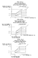
- the outside air temperature control handling characteristic storage unit 52a stores the association between an outside air temperature Ta and a required fan number-of-revolutions Nf as a correspondence characteristic map as shown in FIG. 6(a). That is, with the correspondence map stored therein, when an outside air temperature Ta is inputted, the corresponding required fan number-of-revolutions Nf is set as a target value for rotating the cooling fan 6.
- the water temperature control handling characteristic storage unit 52b stores the association between a cooling water temperature Tw and a required fan number-of-revolutions Nf of the cooling fan 6 as a correspondence characteristic map as shown in FIG. 6(b), and the fluid temperature control handling characteristic storage unit 52c stores the association between a fluid temperature To and a required fan number-of-revolutions Nf of the cooling fan 6 as a correspondence characteristic map as shown in FIG. 6(c).
- the rotation speed characteristic of the cooling fan 6 to be set in the outside air temperature control mode, as shown in FIG. 6(a)
- the required fan number-of-revolutions Nf is set at Nf 11 irrespective of the value of the outside air temperature Ta.
- the required fan number-of-revolutions Nf is set at a greater value.
- the required fan number-of-revolutions Nf is set at Nf 11 and, on the other hand, if the outside air temperature is in a range equal to or higher than the predetermined value Ta 1 but lower than a predetermined value Ta 2 , the required fan number-of-revolutions is set at a larger value so as to correspond to an increase in the outside air temperature.
- the required fan number-of-revolutions does not further increase beyond that, and it is set as a constant value with respect to a variation of the outside air temperature Ta.
- the required fan number-of-revolutions Nf is set at Nf 12 (Nf 31 ⁇ Nf 32 ), and if the outside air temperature Ta is in a range equal to or higher than the predetermined value Ta 1 but lower than the predetermined value Ta 2 , the required fan number-of-revolutions Nf is set at a larger value so as to correspond to an increase in the outside air temperature Ta.
- the required f an number-of-revolutions Nf does not further increase beyond that , and it is set as a constant value with respect to a variation of the outside air temperature.
- the maximum value of the required fan number-of-revolutions Nf is clipped at a predetermined value Nf 13 .
- the upper limit value of the required fan number-of-revolutions Nf is restricted so as to suppress the number of revolutions of the cooling fan 6 without setting the excessively large number of revolutions corresponding to that outside air temperature Ta, thereby enabling the reduction of generated noise.
- the rotation speed characteristic of the cooling fan 6 to be set in the water temperature control mode and the fluid temperature control mode, as shown in FIGs.
- the required fan number-of-revolutions Nf does not further increase beyond that, but it is set as a constant value with respect to the variation of the cooling water temperature Tw and, likewise, in a case in which the fluid temperature To is in a range equal to or more than the predetermined value To 2 , the required fan number-of-revolutions Nf does not further increase beyond that, but it is set as a constant value with respect to the variation of the fluid temperature To.
- the maximum value of the required fan number-of-revolutions Nf is clipped at a predetermined value Nf 23 in the water temperature control mode and is clipped at a predetermined value Nf 33 in the fluid temperature control mode.
- the upper limit value of the required fan number-of-revolutions Nf is restricted so as to suppress the number of revolutions of the cooling fan 6 without setting the excessively large number of revolutions, thereby enabling the reduction of generated noise.
- the required fan number-of-revolutions Nf is set only when the water temperature Tw is in a range equal to or higher than the predetermined value Tw 1 .
- the required fan number-of-revolutions Nf is set only when the fluid temperature To is in a range equal to or higher than To 1 .
- the control signal outputting unit 53 is composed of a required fan number-of-revolutions setting unit 53a for setting the required fan number-of-revolutions as a required value at which the cooling fan 6 is to be rotated, and a PWM signal conversion unit 53c for outputting a PWM signal as a control signal whereby the rotation speed of the cooling fan 6 reaches the required fan number-of-revolutions.
- the required fan number-of-revolutions setting unit 53a is for setting a required fan number-of-revolutions as a target value of the rotation speed of the cooling fan 6 on the basis of the control mode subjected to the judgment in the control mode judgment unit 51 and the above-mentioned respective correspondence map stored in the characteristic storage unit 52.
- the PWM signal conversion unit 53b calculates an input-output number of revolutions ratio in the electronic viscous clutch 7 for rotating the cooling fan 6 at a required fan number-of-revolutions Nf on the basis of the required fan number-of-revolutions Nf set by the required fan number-of-revolutions setting unit 53a and the engine speed Ne corresponding to the number selected by the engine speed dial switch 14, and outputs, to the electronic viscous clutch 7, a PWM signal as an opening-degree control signal to a silicone oil valve 36 for achieving this input-output number-of-revolutions ratio.
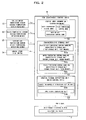
- the control mode judgment unit 51 makes a judgment as to whether or not the cooling water temperature Tw is equal to or higher than the predetermined value Tw 1 . If Tw ⁇ Tw 1 , the water temperature control mode is selected as the PWM control, and the control flow advances to a step A30 and following steps. On the other hand, if Tw ⁇ Tw 1 , the control flow proceeds to a step A50 for further judgment.
- a required fan number-of-revolutions Nf is set from the correspondence map shown in FIG. 6(c) on the basis of the fluid temperature To and the number of the engine speed dial switch 14, and the control flow proceeds to a step A70 to output, to the electronic viscous clutch 7, a PWM signal for rotating the cooling fan 6 at the required fan number-of-revolutions Nf. Then, this flow comes to an end.
- a required fan number-of-revolutions Nf is set from the correspondence map shown in FIG. 6(a) on the basis of the outside air temperature Ta and the number of the engine speed dial switch 14, and the control flow proceeds to a step A90 to output, to the electronic viscous clutch 7, a PWM signal for rotating the cooling fan 6 at the required fan number-of-revolutions Nf. Then, this flow comes to an end.
- the ECM 4 sets a required fan number-of-revolutions Nf required with respect to the cooling water temperature Tw and outputs a PWM signal for rotating the cooling fan 6 at the required fan number-of-revolutions Nf. Therefore, the cooling fan 6 is controlled to the fan number of revolutions corresponding to the cooling water temperature Tw, thereby enabling the implementation of the cooling control corresponding to the temperature state of the cooling water.
- the cooling fan 6 is controlled to the fan number-of-revolutions corresponding to the fluid temperature To, thereby enabling the implementation of the cooling control corresponding to the temperature state of the fluid.
- the ECM 4 sets a required fan number-of-revolutions Nf required with respect to the outside air temperature Ta. Therefore, the cooling fan 6 is controlled to a fan number-of-revolutions corresponding to the outside air temperature Ta, thereby enabling the implementation of the cooling control corresponding to the temperature state of the outside air.
- control since the control is executed by referring to both the outside air temperature and the engine-related liquid temperature, it is possible to carry out the appropriate cooling control suitable for the respective temperature conditions. Moreover, since these control are selected according to the engine-related liquid temperatures (engine cooling water temperature Tw, hydraulic pump working fluid temperature To), it is possible to implement the effective cooling control corresponding to an engine state.
- engine-related liquid temperatures engine cooling water temperature Tw, hydraulic pump working fluid temperature To
- the clutch control is implemented using an electronic control viscous clutch, an accurate input-output number-of-revolutions ratio control on the clutch becomes feasible with high response.
- the ECM 4 has the characteristic storage unit 52 for storing a rotation speed characteristic of the cooling fan 6, the required fan rotation speeds can flexibly set as a correspondence map with respect to an engine speed, a cooling water temperature Tw, a fluid temperature To and an outside air temperature Ta, which enables fine control.
- the required fan number-of-revolutions does not further increase beyond that, but it is set at a constant value. This prevents the setting of an excessively large required fan number-of-revolutions and limits the rotation speed of the cooling fan 6, thereby enabling the reduction of generated noise.
- the cooling fan 6 is made to cool the engine cooling water and hydraulic pump working fluid passing through the cooling package 5, it is also acceptable that the cooling fan 6 further cools other auxiliaries.
- the cooling package 5 includes the radiator and the oil cooler, it is also acceptable that these are individually provided, and that a cooling fan 6 is used for to each of the radiator and the oil cooler.
- the same control is executed for each of the cooling fan (for example, the same control signal is outputted through control means to each of the cooling fans, or other manners), or that the cooling fans are individually controlled (for example, different control signals are outputted through control means to the individual cooling fans, or other manners).
- the rotation speed of the cooling fan 6 is variable by the electronic control viscous clutch 7, all types of clutches are also acceptable, provided that they can vary the ratio (input-output number-of-revolutions ratio) of the number of revolutions inputted from the engine 8 and the number of revolutions of the cooling fan 6. Still additionally, although in the above-described embodiment the rotation speed Nf of the cooling fan 6 is determined according to the conditions on the engine cooling water temperature Tw and hydraulic pump working fluid temperature To used as the engine-related liquid temperatures, it is also possible to detect only one of the cooling water temperature Tw and the fluid temperature To.
- the outside air temperature sensor 13 is made to detect an outside air temperature Ta on an outside air surface of the cooling package 5, in other words, it is made to detect an outside air temperature around a machine body of a construction machine, it is also appropriate to detect an outside air temperature around the engine 8, or to detect an atmospheric temperature in the interior of the engine room 2B or an ambient temperature.
- the engine ambient temperature is detected as an outside air temperature Ta so as to set a required fan number-of-revolutions Nf corresponding thereto.
- the outside air temperature around the machine i.e., the atmospheric temperature on the external side of the cooling package 5
- the outside air temperature Ta so as to set a required fan number-of-revolutions Nf corresponding thereto.
- the ECM 4 is designed to have the memories (first memory, second memory, third memory) as the characteristic storage unit 51 storing a characteristic map on rotation speeds of the cooling fan 6, it is also considerable to employ an arrangement in which the ECM 4 does not have these memories.
- a mathematization is previously made on the characteristic on a rotation speed of the cooling fan 6 required with respect to the inputted outside air temperature Ta and engine-related liquid temperatures Tw, To (for example, a required fan rotation speed is defined as a function of an outside air temperature Ta or engine-related liquid temperatures Tw, To, or other manners) so that the ECM 4 determines a required fan rotation speed on the basis of this mathematical expression.
- control apparatus for an input-output number-of-revolutions ratio variable clutch is not limited to the hydraulic shovel, but it is also applicable to various types of construction machines and vehicles such as a wheel loader, a crane and others.
- this control apparatus for an input-output number-of-revolutions ratio variable clutch is widely applicable to all control apparatus for clutches, such as, in addition to an electromagnetic clutch, a centrifugal clutch, a wet clutch, a dry clutch and a variable speed clutch of powder clutches, which are used for the number-of-revolutions variable control of an engine cooling fan.
Landscapes
- Engineering & Computer Science (AREA)
- General Engineering & Computer Science (AREA)
- Mechanical Engineering (AREA)
- Chemical & Material Sciences (AREA)
- Combustion & Propulsion (AREA)
- Physics & Mathematics (AREA)
- Electromagnetism (AREA)
- Cooling, Air Intake And Gas Exhaust, And Fuel Tank Arrangements In Propulsion Units (AREA)
- Control Of Vehicle Engines Or Engines For Specific Uses (AREA)
- Combined Controls Of Internal Combustion Engines (AREA)
Abstract
Description
- The present invention relates to a control apparatus and control method for an input-output number-of-revolutions ratio variable clutch, which is made to control the ratio between input number-of-revolutions and output number-of-revolutions of a cooling fan driven by an engine.
- So far, in a cooling device made to air-cool the cooling water or working fluid of an engine by using a cooling fan, there has been developed a control apparatus for controlling the number of revolutions of the cooling fan.
For example,Patent Document 1 discloses an arrangement in which, in a working fluid temperature cooling device for a hydraulic pump driven by an engine, a working fluid temperature is detected by a temperature sensor and a cooling fan is rotated at an appropriate number of revolutions of the cooling fan which can provide a cooling capacity corresponding to the detection value. This arrangement can provide the number of revolutions of a cooling fan corresponding to a high temperature for achieving the appropriate cooling even in the case of a high-temperature working fluid and a high flow rate, and can suppress the number of revolutions of the cooling fan to reduce generated noise in the case of a low need for the cooling because the working fluid is in a low-temperature condition. - In addition, in a cooling device designed to introduce cooling water into a radiator for cooling the radiator by an engine driven cooling fan, there has been developed a device in which a clutch varying an engagement state depending upon a variation of ambient temperature is interposed between the engine and the cooling fan. In the case of such a technique, for example, a bimetal or the like is employed for the detection of the ambient temperature and, in a state where the ambient temperature around the clutch is lower than a predetermined temperature, the clutch is left released from the engagement state and the driving force inputted from the engine is not transferred to the cooling fan. On the other hand, if the ambient temperature around the clutch exceeds the predetermined temperature, the engagement of the clutch takes place so that the driving force inputted from the engine is transferred to the cooling fan so as to rotate the cooling fan. Moreover, with such an arrangement, the operation of the cooling fan can be controlled according to the ambient temperature to achieve the appropriate cooling.
Patent Document 1 :Japanese Patent Laid-Open No. 2002-61611 - However, the technique disclosed in
Patent Document 1 and the above-mentioned latter technique cannot achieve the effective cooling control suitable for the engine condition. For example, since the ambient temperature around the clutch varies greatly due to not only the variation of the outside air temperature but also the exhaust heat from various types of devices such as an engine and a hydraulic pump, when the clutch ambient temperature is used as an index of the temperature of cooling air for cooling the radiator, depending upon the location of the clutch, difficulty can be experienced in cooling the radiator appropriately. - In addition, for example, even in a case which the ambient temperature (or the temperature of cooling air) around the clutch is low, depending upon the load states of the engine and the hydraulic pump, it is also considered that the temperature of the engine cooling water or the working fluid temperature of the hydraulic pump increases so that the cooling by the cooling fan becomes necessary. Still additionally, even in a case in which the working fluid pressure of the hydraulic pump is not in a very high temperature condition, for example, if the engine is driven under the blazing sun, there is a need to operate the cooling fan.
- As described above, in the case of the control of the cooling fan, it is considered that the control on the number of revolutions according to only the ambient temperature or working fluid temperature of the hydraulic pump cannot provide a sufficient cooling performance and, hence, minuter control is needed.
The present invention has been developed in consideration of these problems, and it is an object of the invention to provide a control apparatus and control method for an input-output number-of-revolutions ratio variable clutch, capable of implementing the effective cooling control suitable for an engine state. - For achieving the above-mentioned purpose, a control apparatus for an input-output number-of-revolutions ratio variable clutch (claim 1) according to the present invention is characterized by comprising a clutch capable of varying an input-output number-of-revolutions ratio, an input side of which is connected to an engine and an output side of which is connected to a cooling fan, first temperature detecting means for detecting an outside air temperature, second temperature detecting means for detecting a liquid temperature related to the engine and control means for, upon receipt of temperature information from the first temperature detecting means and the second temperature detecting means, changing the input-output number-of-revolutions ratio of the clutch to control a rotating state of the cooling fan, and the control means includes amain control unit for, upon receipt of the engine-related liquid temperature detected by the second temperature detecting means, determining one of a rotation speed of the cooling fan required with respect to the outside air temperature and a rotation speed of the cooling fan required with respect to the engine-related liquid temperature on the basis of a condition on the engine-related liquid temperature and outputting a control signal so that a rotation speed of the cooling fan reaches the required fan rotation speed.
- Preferably, a hydraulic pump is connected to the engine and the cooling fan is made to cool cooling water of the engine and working fluid of the hydraulic pump and the second temperature detecting means is made as means for detecting at least one of a temperature of the cooling water of the engine and a temperature of the working fluid of the hydraulic pump (claim 2).
In addition, preferably, the control means includes comparison means for, upon receipt of temperature information on the engine-related liquid temperature, making a comparison between the engine-related liquid temperature and a set value set in advance and, when the comparison means makes a judgment that the engine-related liquid temperature is lower than the set value, the main control unit determines a first required fan rotation speed required with respect to the outside air temperature and, when the comparison means makes a judgment that the engine-related liquid temperature is equal to or higher than the set value, the main control unit determines a second required fan rotation speed required with respect to the engine-related liquid temperature (claim 3). - Still additionally, preferably, the control means includes a first storage unit for storing a rotation speed characteristic of the cooling fan required with respect to the outside air temperature and a second storage unit for storing a rotation speed characteristic of the cooling fan required with respect to the engine-related liquid temperature (claim 4).
Yet additionally, preferably, the main control unit determines the cooling fan rotation speed by preferentially making a judgment on a condition of the engine-related liquid temperature detected by the second temperature detecting means over a condition of the outside air temperature detected by the first temperature detecting means (claim 5). - Moreover, preferably, the clutch is made as an electronic control viscous clutch (claim 6).
Furthermore, a control apparatus for an input-output number-of-revolutions ratio variable clutch (claim 7) according to the present invention is characterized by comprising an electronic control viscous clutch capable of varying an input-output number-of-revolutions ratio, an input side of which is connected to an engine mounted in a construction machine and an output side of which is connected to a fan made to cool cooling water of the engine and working fluid of a hydraulic pump driven by the engine, an outside temperature sensor for detecting an outside air temperature, a fluid temperature sensor for detecting a working fluid temperature of the hydraulic pump, a cooling water temperature sensor for detecting a cooling water temperature of the engine, and a controller for, upon receipt of temperature information from the outside air temperature sensor, the fluid temperature sensor and the cooling water temperature sensor, changing an input-output number-of-revolutions ratio of the clutch to control a rotation state of the cooling fan, and the controller includes a first memory for storing a rotation speed characteristic of the cooling fan required with respect to the outside air temperature, a second memory for storing a rotation speed characteristic of the cooling fan required with respect to the engine cooling water temperature, a third memory for storing a rotation speed characteristic of the cooling fan required with respect to the hydraulic pump working fluid temperature, comparison means for, upon receipt of temperature information from the cooling water temperature sensor and the fluid temperature sensor, making a comparison between the engine cooling water temperature and a first set value and making a comparison between the hydraulic pump working fluid temperature and a second set value, and a main control unit for, when the comparison means indicates that the engine cooling water temperature is lower than the first set value and the hydraulic pump working fluid temperature is lower than the second set value, determining a corresponding required fan rotation speed from the first memory and, when the engine cooling water temperature is equal to or higher than the first set value, determining a corresponding required fan rotation speed from the second memory and, when the hydraulic pump working fluid temperature is equal to or higher than the second set value, determining a corresponding required fan rotation speed from the third memory and for outputting a control signal so that a rotation speed of the cooling fan reaches the above-mentioned required fan rotation speed. - Preferably, the main control unit clips upper limits of the required fan rotation speed required with respect to the outside air temperature and the cooling fan rotation speed required with respect to the engine-related liquid temperature for making a restriction (claim 8).
Furthermore, a control method for an input-output number-of-revolutions ratio variable clutch (claim 9) according to the present invention is characterized in that, in an arrangement using a clutch capable of varying an input-output number-of-revolutions ratio, an input side of which is connected to an engine and an output side of which is connected to a cooling fan, first temperature detecting means for detecting an outside air temperature, second temperature detecting means for detecting a liquid temperature related to the engine and control means for, upon receipt of temperature information from the first temperature detecting means and the second temperature detecting means, changing the input-output number-of-revolutions ratio of the clutch to control a rotation of the cooling fan, the engine-related liquid temperature detected by the second temperature detecting means is received, and one of a rotation speed of the cooling fan required with respect to the outside air temperature and a rotation speed of the cooling fan required with respect to the engine-related liquid temperature is determined according to a condition on the engine-related liquid temperature and a control signal is outputted so that a rotation speed of the cooling fan reaches this required fan rotation speed. - Still furthermore, in accordance with the present invention, a control method for an input-output number-of-revolutions ratio variable clutch (claim 10) capable of executing variable control on an input-output number-of-revolutions ratio, an input side of which is connected to an engine and an output side of which is connected to a cooling fan, is characterized in that, in an arrangement using control means carrying out at least two types of control for determining a rotation speed of the cooling fan on the basis of an outside air temperature and for determining a rotation speed of the cooling fan on the basis of an engine-related liquid temperature, the outside air temperature is detected and the engine-related liquid temperature is detected and, through the use of the control means, the control based on the engine-related liquid temperature is preferentially executed over the control based on the outside air temperature.
- Although it is preferable that the outside air temperature is an outside air temperature around a machine body, it is also appropriate that it is an outside air temperature around the engine, or that it is an ambient temperature of the engine.
- With a control apparatus for an input-output number-of-revolutions ratio variable clutch and control method for an input-output number-of-revolutions ratio variable clutch (
claims 1 and 9) according to the present invention, the input-output number-of-revolutions ratio of the clutch is controllable by referring to both the outside air temperature and the engine-related liquid temperature, which can achieve appropriate cooling control. Moreover, since the determination of the required fan rotation speed is made according to a condition on the engine-related liquid temperature, it is possible to carry out the effective cooling control suitable for an engine state. - In addition, a control apparatus for an input-output number-of-revolutions ratio variable clutch (claim 2) according to the present invention can suitably set the required cooling performance (rotation speed of the cooling fan) of the cooling fan.
Still additionally, a control apparatus for an input-output number-of-revolutions ratio variable clutch (claim 3) according to the present invention can accurately set the magnitude of the number of revolutions of the cooling fan to be outputted from the clutch, according to the magnitude of the required cooling performance of the cooling fan. - Yet additionally, with a control apparatus for an input-output number-of-revolutions ratio variable clutch (claim 4) according to the present invention, since a storage unit is provided which stores the rotation speed characteristic of the cooling fan, the flexible setting of a required fan rotation speed is feasible.
Moreover, with a control apparatus for an input-output number-of-revolutions ratio variable clutch and control method for an input-output number-of-revolutions ratio variable clutch (claims 5 and 10) according to the present invention, the influence of external factors such as the weather or working environments is suppressible, thereby enhancing the cooling effect of the cooling fan. - Still moreover, with a control apparatus for an input-output number-of-revolutions ratio variable clutch (claim 6) according to the present invention, since the clutch control is carried out with an electronic control viscous clutch, the accurate implementation of the clutch input-output number-of-revolutions ratio control is feasible with high response.
Yet moreover, a control apparatus for an input-output number-of-revolutions ratio variable clutch (claim 7) according to the present invention can control the clutch input-output number-of-revolutions ratio by referring to an outside air temperature, an engine cooling water temperature and a hydraulic pump working fluid temperature. In addition, since the rotation speed of the cooling fan is set according to the conditions on the engine cooling water temperature and the hydraulic pump working fluid temperature, the effective cooling control based on not only an outside air temperature but also an engine state is executable with accuracy. - Furthermore, the magnitude of the number of revolutions of the cooling fan to be outputted from the clutch can accurately be set according to the magnitude of the required cooling performance of the cooling fan and, because of the employment of a memory for storing fan rotation speed characteristic, the flexible setting of the magnitude of the required cooling characteristic becomes feasible, thereby enabling the minute optimum control under specified conditions.
Still furthermore, with a control apparatus for an input-output number-of-revolutions ratio variable clutch (claim 8) according to the present invention, because of the restriction on the upper limit of the required fan rotation speed, it is possible to suppress the noises stemming from the rotations of the cooling fan. -
- [FIG. 1] is an illustrative plan view principally showing an arrangement in an engine room in a construction machine equipped with a control apparatus for an input-output number-of-revolutions ratio variable clutch according to an embodiment of the present invention.
- [FIG. 2] is a block diagram showing a functional arrangement of a control apparatus for an input-output number-of-revolutions ratio variable clutch according to an embodiment of the present invention.
- [FIG. 3] is a cross-sectional view showing an electronic viscous clutch related to a control apparatus for an input-output number-of-revolutions ratio variable clutch according to an embodiment of the present invention.
- [FIG. 4] is an illustration of an arrangement of a cooling fan related to a control apparatus for an input-output number-of-revolutions ratio variable clutch according to an embodiment of the present invention, and is a vertical cross-sectional view showing a state in which the cooling fan is mounted on an electronic viscous clutch.
- [FIG. 5] is a control flow illustration for explaining clutch input-output number-of-revolutions ratio control by an input-output number-of-revolutions ratio variable clutch according to an embodiment of the present invention.
- [FIGs. 6] are graphic illustrations of cooling fan control characteristics in an input-output number-of-revolutions ratio variable clutch according to an embodiment of the present invention, and FIG. 6(a) is a graph showing a required fan number-of-revolutions characteristic relative to an outside air temperature, FIG. 6(b) is a graph showing a required fan number-of-revolutions characteristic relative to an engine cooling water temperature and FIG. 6(c) is a graph showing a required fan number-of-revolutions characteristic relative to a hydraulic pump working fluid temperature.
- [FIG. 7] is a side-elevational view showing the entire arrangement of a construction machine equipped with an input-output number-of-revolutions ratio variable clutch according to an embodiment of the present invention.
-
- 1
- Lower traveling body
- 2
- Upper revolving body
- 2A
- Cabin
- 2B
- Engine room
- 2C
- Counter-weight
- 2D
- Exhaust port
- 3
- Working apparatus
- 4
- ECM (Electronic control unit, Control means, Controller)
- 5
- Cooling package
- 6
- Cooling fan (Fan for cooling)
- 7
- Electronic viscous clutch (Clutch)
- 8
- Engine
- 9
- Hydraulic pump
- 10
- Fan pulley
- 11
- Cooling water temperature sensor (Second temperature detecting means)
- 12
- Fluid temperature sensor (Second temperature detecting means)
- 13
- Outside air temperature sensor (First temperature detecting means)
- 14
- Engine speed dial switch
- 21
- Input shaft
- 22
- Input plate
- 22a
- Input side spline
- 23
- Output plate
- 23a
- Output side spline
- 24
- Revolving main body
- 25
- Space
- 26
- Bearing
- 27
- Fan attaching hole
- 41
- Fin
- 42
- Fan attaching bolt
- 43
- Fan attaching nut
- 44
- Attaching hole
- 45
- Inserting hole
- 51
- Control mode judgment unit (Comparison means)
- 52
- Characteristic storage unit
- 52a
- Outside air temperature control handling characteristic storage unit (first storage unit, First memory)
- 52b
- Water temperature handling characteristic storage unit (Second storage unit, Second memory)
- 52c
- Fluid temperature handling characteristic storage unit (Second storage unit, Third memory)
- 53
- Control signal outputting unit (Main control unit)
- 53a
- Required fan number-of-revolutions setting unit
- 53b
- PWM signal conversion unit
- As shown in FIG. 7, a construction machine equipped with a control apparatus for an input-output number-of-revolutions ratio variable clutch according to an embodiment of the present invention is made up of three sections of a
lower traveling body 1, an upper revolvingbody 2 located above thelower traveling body 1 to be rotatable, and a workingapparatus 3 provided in the upper revolvingbody 2 for conducting various operations. Of these sections, in the upper revolvingbody 2, acabin 2A functioning as a driver's cab of the construction machine is disposed at a front portion thereof, anengine room 2B is placed in a housing cover in the rear of thecabin 2A, and acounter-weight 2C is located in the rear thereof. - As shown in FIG. 1, in the
engine room 2B, an ECM (electronic control unit, control means, controller) 4 is disposed in the rear of thecabin 2A, and in the rear of the vehicle body with respect to theECM 4, acooling package 5 having a radiator and an oil cooler, a cooling fan (fan for cooling) 6, an electronic viscous clutch (clutch) 7, anengine 8 and anoil pump 9 are disposed in this order from the left side of the machine body. In this embodiment, theengine 8 is made to drive thehydraulic pump 9 and thehydraulic pump 9 is made to drive the respective devices of the upper revolvingbody 2 including thelower traveling body 1 and the workingapparatus 3 , and with respect to the cooling fan, theengine 8 is designed to drive it directly as mentioned later. - In addition, a cooling
water temperature sensor 11 is provided in theengine 8 so as to detect a temperature Tw of the engine cooling water, afluid temperature sensor 12 is placed in thehydraulic pump 9 to detect a working fluid (hydraulic pump working fluid temperature) To, and an outsideair temperature sensor 13 is set in an outside air surface of thecooling package 5 to detect an outside air temperature Ta. Still additionally, a signal having the information on the cooling water temperature Tw, the fluid temperature To and the outside air temperature Ta (in the following description, the signal having these information will sometimes be referred to simply as cooling water temperature Tw, fluid temperature To and outside air temperature Ta), detected by the respective sensors, is outputted to theECM 4. - Yet additionally, in the
cabin 2A, an enginespeed dial switch 14 is provided for setting a rotation speed of theengine 8 through an operation by an operator. In this case, a selection from five steps fromnumber 1 tonumber 5 can be made from a low rotation speed of theengine 8 up to a high rotation speed thereof according to the working contents (for example, working load and others) of the working machine, and a signal having the information on the number of the dial switch (in the following description, the signal having these information will sometimes be referred to simply as dial switch number) selected in this way is outputted to theECM 4 so that the rotation speed of theengine 8 is controlled to an engine rotation speed Ne corresponding to each of the numbers. - The cooling
fan 6 is disposed in a state where its axial direction is directed at a horizontal direction of the machine body, and is made to suck the outside air as cooling wind from an inlet port, not shown, formed in a left-side wall of theengine room 2B. At the passing through thecooling package 5 shown by an arrow W, the sucked cooling air cools the engine cooling water and working fluid flowing in the interiors of the radiator and oil cooler located in thecooling package 5. Moreover, the cooling air passing through thecooling package 5 and discharged from the coolingfan 6 is exhausted from an exhaust port, formed in an upper portion of theengine room 2B, to the exterior of the machine. - The electronic
viscous clutch 7 is an electronic clutch device for carrying out the variable control on the number of revolutions of the coolingfan 6 , which is interposed between theengine 8 and the coolingfan 6.
First, as shown in FIGs. 1 and 3, aninput shaft 21 on the input side of the electronicviscous clutch 7 is connected through apulley 10 to theengine 8, and the output side thereof is connected to the coolingfan 6. Moreover, as shown in FIG. 3, in the interior of the electronicviscous clutch 7, aninput plate 22 is placed to extend from theinput shaft 21 in a vertical direction. Thus, theinput plate 21 is made to rotate in a plane generally perpendicular to the input shaft in accordance with a rotating force inputted from theengine 8. - On the other hand, around the
input shaft 21, a revolving main body is placed to slide through abearing 26 with respect to theinput shaft 21, and anoutput plate 23 arranged side by side in confront relation to theinput plate 22 is fixedly secured to the revolvingmain body 24. In the confronting surfaces of theinput plate 22 and theoutput plate 23, aninput side spline 22a and anoutput side spline 23a are formed to have groove-like concave and convex configurations, respectively, and are rotated with respect to theinput shaft 21 with their being in a non-contact state and a predetermined space being maintained between there. - A
space 25 defined by theinput plate 22 and theoutput plate 23 is filled with a silicone oil having a predetermined viscosity. This silicone oil is used as a rotational motion transferring medium from theinput plate 22 side to theoutput plate 23 side and is made to circulate in the interior of the electronicviscous clutch 7 through a valve, not shown, provided in the interior of the electronicviscous clutch 7. Moreover, the liquid pressure of the silicone oil put in the confronting surfaces of theinput plate 22 and theoutput plate 23 is controlled in a manner such that the internal flow rate of the silicone oil is increased or decreased by opening or closing the valve, thereby controlling the ratio of the numbers of revolutions transferred from theinput plate 22 to theoutput plate 23 side. - For example, when the valve is closed, the internal flow of the silicone oil is stopped so as to reduce the engagement state between the
input side spline 22a and theoutput side spline 23a, thereby reducing the transfer of the revolving force from theinput plate 22 to theoutput plate 23. Conversely, when the valve is opened, since the silicone oil circulates in the interior of the clutch 7, the engagement state between theinput side spline 22a and theoutput side spline 23a is enhanced, thereby enhancing the transfer of the revolving force from theinput plate 22 to theoutput plate 23, which increases the ratio of the number of revolutions of the revolvingmain body 24 with respect to the number of revolutions of theinput shaft 21. - In addition, the revolving
main body 24 hasfan attaching holes 27 used for attaching the coolingfan 6. That is, the coolingfan 6 is rotated together with the revolvingmain body 24 and, when the number-of-revolutions ratio increases in the electronicviscous clutch 7, the ratio of number of revolutions of the coolingfan 6, attached to the revolvingmain body 24, with respect to the number of revolutions of theinput shaft 21 also increases.
The electronicviscous clutch 7 in this embodiment is designed to be capable of controlling the number-of-revolutions ratio transferred from theinput plate 22 side to theoutput 23 side by controlling the internal flow rate of the silicone oil put in the confronting surfaces of theinput plate 22 and theoutput plate 23. - In this connection, in this embodiment, the
ECM 4, mentioned later, controls the excitation time of a solenoid, provided in the interior of the electronicviscous clutch 7, in units of very short time (varies the ratio of the excitation and the non-excitation per unit time in a digital manner), thus implementing the PWM (Pulse Width Modulation) which controls the internal flow rate of the silicone oil flexibly. This enables the ratio of the number of revolutions of the revolvingmain body 24 to the number of revolutions of theinput shaft 21 to be controlled without restrictions. - As shown in FIG. 4, the cooling
fan 6 has afin 41 for sucking cooling air from the exterior of the machine by rotation, an insertinghole 45 for the insertion in the revolvingmain body 24 of the electronicviscous clutch 7 and attachingholes 44 made at the positions corresponding to thefin attaching holes 2 7 at the insertion of the coolingfan 6 into the revolvingmain body 24, andfan attaching bolts 42 are inserted into thefan attaching holes 27 and the attachingholes 44 and the coolingfan 6 is fixedly secured to the revolvingmain body 24 by tightening fan attaching nuts 43. In this way, the coolingfan 6 and the revolvingmain body 24 are rotated in a unitary manner. - As FIG. 2 shows, the
ECM 4 receives the respective input information from a coolingwater temperature sensor 11 and a fluid temperature sensor 12 (both are second temperature detecting means), an outside air temperature sensor (first temperature detecting means) 13, and an enginespeed dial switch 14. ThisECM 4 is an electronic control unit for carrying out the PWM control on the electronicviscous clutch 7 on the basis of the respective input information mentioned above. In this embodiment, as the PWM control, there are selected and implemented three control modes of a water temperature control mode, a fluid temperature control mode and an outside air temperature control mode. - First, the
ECM 4 includes a control mode judgment unit (comparison means) 51 for making a judgment as to which of these three control modes is selected, acharacteristic storage unit 52 for storing a rotation speed characteristic of the coolingfan 6 and a control signal outputting unit (main control unit) 53 for setting a required fan number-of-revolutions (required fan rotation speed) as a target value when the coolingfan 6 is rotated on the basis of the respective input information and for outputting a PWM signal as a control signal whereby the rotation speed of the coolingfan 6 becomes the required fan number-of-revolutions. - The control
mode judgment unit 51 makes a judgment whether or not a cooling water temperature Tw inputted from the coolingwater temperature sensor 11 is equal to or higher than a water temperature control start water temperature Tw1 (first set value) which is a predetermined value set in advance. In a case in which the cooling water temperature Tw is equal to or higher than Tw1, the water temperature control mode is selected. That is, the predetermined value Tw1 is set as a lower limit of the cooling water temperature Tw in a state the water temperature control mode is to be selected, and when the cooling water temperature Tw is equal to or higher than Tw1, for example, even if the outside air temperature or the hydraulic pump working fluid temperature takes a normal temperature, the water control mode is selected. - Moreover, when the cooling water temperature Tw stands at Tw < Tw1, the control
mode judgment unit 51 makes a judgment as to whether or not a fluid temperature To inputted from thefluid temperature sensor 12 is equal to or higher than a fluid temperature control start fluid temperature To1 (second set value) which is a predetermined value set in advance. If the fluid temperature To ≥ To1, the fluid temperature control mode is selected. That is, the predetermined value To1 is set as a lower limit of the fluid temperature To in a state the fluid temperature control mode is to be selected, and if the fluid temperature To is equal to or higher than To1, for example, even in a case in which the outside air temperature is a normal temperature, the fluid temperature control mode is selected. - Still moreover, If the fluid temperature To < To1, the control
mode judgment unit 51 selects the outside air temperature control mode. Thus, for the control mode selection in the PWM control, the controlmode judgment unit 51 preferentially makes a judgment on the magnitude of the cooling water temperature Tw, and secondly makes a judgment on the magnitude of the fluid temperature To and selects the outside air temperature control mode only when both the cooling water temperature Tw and the fluid temperature To are lower than predetermined values. - The reason that a control mode of the PWM control is selected according to a condition on an engine-related liquid temperature (cooling water temperature TW, fluid temperature To) is as follows.
That is, taking note of the engine cooling water and working fluid flowing in the interior of thecooling package 5, the cooling air introduced into theengine room 2B by the coolingfan 6 acts to take the heat away from the engine cooling water and working fluid flowing in thecooling package 5 for accomplishing the cooling of the engine cooling water and the working fluid and, hence, the cooling effect increases as the temperature of the cooling air (i.e., outside air temperature) becomes lower, while the cooling effect reduces as the temperature of the cooling air becomes higher. - Therefore, for obtaining the cooling effect stable without depending on the temperature of cooling air, it is preferable that the number of revolutions of the cooling fan is increased as the temperature of the cooling air becomes higher so as to increase the wind velocity of the cooling air for enhancing the cooling effect.
However, since the temperatures of the engine cooling water and working fluid flowing in thecooling package 5 varies according to the load of the engine 8 (i.e., load of the hydraulic pump 9) or the driving time, even if the cooling effect in thecooling package 5 is stable without depending on the temperature of the cooling wind, the temperatures of the engine cooling water and working fluid rise so that difficulty can be encountered in providing a sufficient cooling effect. - In addition, in comparison with the engine-related liquid temperature, the outside air temperature tends to vary because of being more easily influenced by external factors such as weather and working environments. For this reason, in this embodiment, a judgment is preferentially made with respect to the magnitudes of the engine cooling water temperature Tw and the hydraulic pump working fluid temperature To which are the engine-related fluid temperatures so as to carry out the control based on the cooling water temperature Tw and the fluid temperature To, and the control based on the outside air temperature Ta is executed only when the cooling water temperature Tw and the fluid temperature To are lower than the predetermined values, respectively.
- The
characteristic storage unit 52 stores a rotation speed characteristic of the coolingfan 6 corresponding to each of the control modes selected by the controlmode judgment unit 51 and it is composed of an outside air temperature control handling characteristic storage unit (first storage unit, first memory) 52a corresponding to the outside air temperature control mode, a water temperature control handling characteristic storage unit (second storage unit, second memory) 52b corresponding to the water temperature control mode and a fluid temperature control handling characteristic storage unit (second storage unit, third memory) 52c corresponding to the fluid temperature control mode. - The outside air temperature control handling
characteristic storage unit 52a stores the association between an outside air temperature Ta and a required fan number-of-revolutions Nf as a correspondence characteristic map as shown in FIG. 6(a). That is, with the correspondence map stored therein, when an outside air temperature Ta is inputted, the corresponding required fan number-of-revolutions Nf is set as a target value for rotating the coolingfan 6. - The water temperature control handling
characteristic storage unit 52b stores the association between a cooling water temperature Tw and a required fan number-of-revolutions Nf of the coolingfan 6 as a correspondence characteristic map as shown in FIG. 6(b), and the fluid temperature control handlingcharacteristic storage unit 52c stores the association between a fluid temperature To and a required fan number-of-revolutions Nf of the coolingfan 6 as a correspondence characteristic map as shown in FIG. 6(c).
With respect to the rotation speed characteristic of the coolingfan 6 to be set in the outside air temperature control mode, as shown in FIG. 6(a), when the selected number of the enginespeed dial switch 14 is thenumber 1, the required fan number-of-revolutions Nf is set at Nf11 irrespective of the value of the outside air temperature Ta. Moreover, as the number of the enginespeed dial switch 14 becomes larger (with an increase of the engine speed Ne), the required fan number-of-revolutions Nf is set at a greater value. - Moreover, in a case in which the selected numbers of the engine
speed dial switch 14 arenumbers - In addition, in a case in which the selected numbers of the engine
speed dial switch 14 arenumbers speed dial switch 14 isnumber 5 at which the engine speed Ne reaches a maximum, the maximum value of the required fan number-of-revolutions Nf is clipped at a predetermined value Nf13. - Thus, even if the outside air temperature Ta stands at the predetermined value Ta2 or more, the upper limit value of the required fan number-of-revolutions Nf is restricted so as to suppress the number of revolutions of the cooling
fan 6 without setting the excessively large number of revolutions corresponding to that outside air temperature Ta, thereby enabling the reduction of generated noise.
Moreover, as well as the rotation speed characteristic of the coolingfan 6 to be set in the water temperature control mode and the fluid temperature control mode, as shown in FIGs. 6(b) and 6(c), when the selected number of the enginespeed dial switch 14 isnumber 1, the required fan number-of-revolutions Nf is set at Nf21 or Nf31 at all times, and as the number of the enginespeed dial switch 14 becomes larger (the engine speed Ne increases), the required fan number-of-revolutions Nf is set at a larger value. Still moreover, in a case in which the cooling water temperature Tw is in a range equal to or more than the predetermined value Tw2, the required fan number-of-revolutions Nf does not further increase beyond that, but it is set as a constant value with respect to the variation of the cooling water temperature Tw and, likewise, in a case in which the fluid temperature To is in a range equal to or more than the predetermined value To2, the required fan number-of-revolutions Nf does not further increase beyond that, but it is set as a constant value with respect to the variation of the fluid temperature To. - Yet additionally, in a case in which the number of the engine
speed dial switch 14 isnumber 5 at which the engine speed Ne reaches a maximum, the maximum value of the required fan number-of-revolutions Nf is clipped at a predetermined value Nf23 in the water temperature control mode and is clipped at a predetermined value Nf33 in the fluid temperature control mode.
Thus, even if the cooling water temperature Tw and the fluid temperature To stand at the predetermined values Tw2 or more and To2 or more, respectively, the upper limit value of the required fan number-of-revolutions Nf is restricted so as to suppress the number of revolutions of the coolingfan 6 without setting the excessively large number of revolutions, thereby enabling the reduction of generated noise. - Since the water temperature control mode is selected only when the control
mode judgment unit 51 shows that the cooling water temperature Tw is equal to or higher than the predetermined value Tw1 (first set value), also in the correspondence map on the required fan number-of-revolutions Nf, as shown in FIG. 6(b), the required fan number-of-revolutions Nf is set only when the water temperature Tw is in a range equal to or higher than the predetermined value Tw1. Likewise, also with respect to the fluid temperature control mode, as shown in FIG. 6(c), the required fan number-of-revolutions Nf is set only when the fluid temperature To is in a range equal to or higher than To1. - The control
signal outputting unit 53 is composed of a required fan number-of-revolutions setting unit 53a for setting the required fan number-of-revolutions as a required value at which the coolingfan 6 is to be rotated, and a PWM signal conversion unit 53c for outputting a PWM signal as a control signal whereby the rotation speed of the coolingfan 6 reaches the required fan number-of-revolutions.
The required fan number-of-revolutions setting unit 53a is for setting a required fan number-of-revolutions as a target value of the rotation speed of the coolingfan 6 on the basis of the control mode subjected to the judgment in the controlmode judgment unit 51 and the above-mentioned respective correspondence map stored in thecharacteristic storage unit 52. - The PWM
signal conversion unit 53b calculates an input-output number of revolutions ratio in the electronicviscous clutch 7 for rotating the coolingfan 6 at a required fan number-of-revolutions Nf on the basis of the required fan number-of-revolutions Nf set by the required fan number-of-revolutions setting unit 53a and the engine speed Ne corresponding to the number selected by the enginespeed dial switch 14, and outputs, to the electronicviscous clutch 7, a PWM signal as an opening-degree control signal to a silicone oil valve 36 for achieving this input-output number-of-revolutions ratio. - Secondly, referring to a control flow shown in FIG. 5, a description will be given of concrete control in this input-output number-of-revolutions ration variable clutch control apparatus. This flow is properly called as a subroutine at every predetermined cycle (for example, cycle synchronized with a cycle of information detection by the cooling
water temperature sensor 11, thefluid temperature sensor 12, the outsideair temperature sensor 13 or the like) in theECM 4. - First of all, at a step A10, to the
ECM 4, there are inputted an engine speed Ne corresponding to the number selected by the enginespeed dial switch 14, a cooling water temperature Tw detected by the coolingwater temperature sensor 14, a hydraulic pump working fluid temperature To detected by thefluid temperature sensor 12 and an outside air temperature Ta detected by the outsideair temperature sensor 13.
Following this, at a step A20, the controlmode judgment unit 51 makes a judgment as to whether or not the cooling water temperature Tw is equal to or higher than the predetermined value Tw1. If Tw ≥ Tw1, the water temperature control mode is selected as the PWM control, and the control flow advances to a step A30 and following steps. On the other hand, if Tw < Tw1, the control flow proceeds to a step A50 for further judgment. - That is, at the step A50, a judgment is made as to whether or not the fluid temperature To is equal to or higher than the predetermined value To1. If To≥To1, the fluid temperature control mode is selected as the PWM control, and the control flow goes to a step A60 and following steps. If To < To1, the outside air temperature control mode is selected as the PWM control, and the control flow advances to a step A80 and following steps.
In a case in which the water temperature control mode is selected at the step A20, at the step A30, a required fan number-of-revolutions Nf is set from the correspondence map shown in FIG. 6(b) on the basis of the cooling water temperature Tw and the number of the enginespeed dial switch 14, and the control flow proceeds to a step A40 to output, to the electronicviscous clutch 7, a PWM signal for rotating the coolingfan 6 at the required fan number-of-revolutions Nf. Then, this flow comes to an end. - Moreover, when the fluid temperature control mode is selected at the step A50, at a step A60, a required fan number-of-revolutions Nf is set from the correspondence map shown in FIG. 6(c) on the basis of the fluid temperature To and the number of the engine
speed dial switch 14, and the control flow proceeds to a step A70 to output, to the electronicviscous clutch 7, a PWM signal for rotating the coolingfan 6 at the required fan number-of-revolutions Nf. Then, this flow comes to an end. - Still moreover, when the outside air temperature control mode is selected at the step A50, at a step A80, a required fan number-of-revolutions Nf is set from the correspondence map shown in FIG. 6(a) on the basis of the outside air temperature Ta and the number of the engine
speed dial switch 14, and the control flow proceeds to a step A90 to output, to the electronicviscous clutch 7, a PWM signal for rotating the coolingfan 6 at the required fan number-of-revolutions Nf. Then, this flow comes to an end. - On the control apparatus for an input-output number-of-revolutions ratio variable clutch according to this embodiment, through the use of the above-described control, when the cooling water temperature Tw detected by the cooling
water temperature sensor 11 is equal to or higher than the predetermined value Tw1, theECM 4 sets a required fan number-of-revolutions Nf required with respect to the cooling water temperature Tw and outputs a PWM signal for rotating the coolingfan 6 at the required fan number-of-revolutions Nf. Therefore, the coolingfan 6 is controlled to the fan number of revolutions corresponding to the cooling water temperature Tw, thereby enabling the implementation of the cooling control corresponding to the temperature state of the cooling water. - Moreover, when the cooling water temperature is lower than the predetermined value Tw1, a judgment is made on the basis of the fluid temperature To and, if the fluid temperature To is equal to or higher than the predetermined To1, the
ECM 4 sets a required fan number-of-revolutions Nf required with respect to the fluid temperature To. Therefore, the coolingfan 6 is controlled to the fan number-of-revolutions corresponding to the fluid temperature To, thereby enabling the implementation of the cooling control corresponding to the temperature state of the fluid.
Still moreover, if the fluid temperature To is lower than the predetermined value To1, theECM 4 sets a required fan number-of-revolutions Nf required with respect to the outside air temperature Ta. Therefore, the coolingfan 6 is controlled to a fan number-of-revolutions corresponding to the outside air temperature Ta, thereby enabling the implementation of the cooling control corresponding to the temperature state of the outside air. - Thus, since the control is executed by referring to both the outside air temperature and the engine-related liquid temperature, it is possible to carry out the appropriate cooling control suitable for the respective temperature conditions. Moreover, since these control are selected according to the engine-related liquid temperatures (engine cooling water temperature Tw, hydraulic pump working fluid temperature To), it is possible to implement the effective cooling control corresponding to an engine state.
- In addition, since the clutch control is implemented using an electronic control viscous clutch, an accurate input-output number-of-revolutions ratio control on the clutch becomes feasible with high response.
Still additionally, since theECM 4 has thecharacteristic storage unit 52 for storing a rotation speed characteristic of the coolingfan 6, the required fan rotation speeds can flexibly set as a correspondence map with respect to an engine speed, a cooling water temperature Tw, a fluid temperature To and an outside air temperature Ta, which enables fine control. - Yet additionally, according to this embodiment, in a range where the cooling water temperature Tw is equal to or higher than the predetermined value Tw2, in a range where the fluid temperature To is equal to or higher than the predetermined value To2 and in a range where the outside air temperature Ta is equal to or higher than the predetermined value Ta2, the required fan number-of-revolutions does not further increase beyond that, but it is set at a constant value. This prevents the setting of an excessively large required fan number-of-revolutions and limits the rotation speed of the cooling
fan 6, thereby enabling the reduction of generated noise. - Although the embodiments of the present invention have been described above, the present invention is not limited to these embodiments, and it is possible to make all changes which do not constitute departures from the spirit and scope of the invention.
For example, although in the above-described embodiment the coolingfan 6 is made to cool the engine cooling water and hydraulic pump working fluid passing through thecooling package 5, it is also acceptable that the coolingfan 6 further cools other auxiliaries. Moreover, although in the above-described embodiment thecooling package 5 includes the radiator and the oil cooler, it is also acceptable that these are individually provided, and that a coolingfan 6 is used for to each of the radiator and the oil cooler. In this case, it is also possible that the same control is executed for each of the cooling fan (for example, the same control signal is outputted through control means to each of the cooling fans, or other manners), or that the cooling fans are individually controlled (for example, different control signals are outputted through control means to the individual cooling fans, or other manners). - In addition, although in the above-described embodiment the rotation speed of the cooling
fan 6 is variable by the electronic controlviscous clutch 7, all types of clutches are also acceptable, provided that they can vary the ratio (input-output number-of-revolutions ratio) of the number of revolutions inputted from theengine 8 and the number of revolutions of the coolingfan 6.
Still additionally, although in the above-described embodiment the rotation speed Nf of the coolingfan 6 is determined according to the conditions on the engine cooling water temperature Tw and hydraulic pump working fluid temperature To used as the engine-related liquid temperatures, it is also possible to detect only one of the cooling water temperature Tw and the fluid temperature To. - Yet additionally, although in the above-described embodiment the outside
air temperature sensor 13 is made to detect an outside air temperature Ta on an outside air surface of thecooling package 5, in other words, it is made to detect an outside air temperature around a machine body of a construction machine, it is also appropriate to detect an outside air temperature around theengine 8, or to detect an atmospheric temperature in the interior of theengine room 2B or an ambient temperature. For example, in the above-described embodiment, it is considered that, at setting the map characteristic shown in FIG. 6(a), when the influence of the engine ambient temperature is reflected in the fan number-of-revolutions control, the engine ambient temperature is detected as an outside air temperature Ta so as to set a required fan number-of-revolutions Nf corresponding thereto. On the other hand, when the influence on the cooling effect stemming from a variation of the outside air temperature (i.e., temperature variation of cooling wind) is reflected in the fan number-of-revolutions control, as well as the above-described embodiment, the outside air temperature around the machine, i.e., the atmospheric temperature on the external side of thecooling package 5, can be detected as an outside air temperature Ta so as to set a required fan number-of-revolutions Nf corresponding thereto. - Furthermore, although in the above-described embodiment the
ECM 4 is designed to have the memories (first memory, second memory, third memory) as thecharacteristic storage unit 51 storing a characteristic map on rotation speeds of the coolingfan 6, it is also considerable to employ an arrangement in which theECM 4 does not have these memories. For example, a mathematization is previously made on the characteristic on a rotation speed of the coolingfan 6 required with respect to the inputted outside air temperature Ta and engine-related liquid temperatures Tw, To (for example, a required fan rotation speed is defined as a function of an outside air temperature Ta or engine-related liquid temperatures Tw, To, or other manners) so that theECM 4 determines a required fan rotation speed on the basis of this mathematical expression. This can provide the advantages and effects equivalent to those in the above-described embodiments. - Although in the above-described embodiment the present invention is applied as an example to a hydraulic shovel which is a construction machine, the control apparatus for an input-output number-of-revolutions ratio variable clutch according to the present invention is not limited to the hydraulic shovel, but it is also applicable to various types of construction machines and vehicles such as a wheel loader, a crane and others.
In addition, this control apparatus for an input-output number-of-revolutions ratio variable clutch is widely applicable to all control apparatus for clutches, such as, in addition to an electromagnetic clutch, a centrifugal clutch, a wet clutch, a dry clutch and a variable speed clutch of powder clutches, which are used for the number-of-revolutions variable control of an engine cooling fan.
Claims (10)
characterized by comprising:
said cooling fan is made to cool cooling water of said engine and working fluid of said hydraulic pump, and
said second temperature detecting means is made as means for detecting at least one of a temperature of the cooling water of said engine and a temperature of the working fluid of said hydraulic pump.
when said comparison means makes a judgment that the engine-related liquid temperature is lower than the set value, said main control unit determines a first required fan rotation speed required with respect to the outside air temperature and, when said comparison means makes a judgment that the engine-related liquid temperature is equal to or higher than the set value, said main control unit determines a second required fan rotation speed required with respect to the engine-related liquid temperature.
characterized in that, in an arrangement using a clutch capable of varying an input-output number-of-revolutions ratio, an input side of which is connected to an engine and an output side of which is connected to a cooling fan, first temperature detecting means for detecting an outside air temperature, second temperature detecting means for detecting a liquid temperature related to said engine and control means for, upon receipt of temperature information from said first temperature detecting means and said second temperature detecting means, changing the input-output number-of-revolutions ratio of said clutch to control a rotation of said cooling fan, the engine-related liquid temperature detected by the second temperature detecting means is received, and one of a rotation speed of said cooling fan required with respect to the outside air temperature and a rotation speed of said cooling fan required with respect to the engine-related liquid temperature is determined according to a condition of the engine-related liquid temperature and a control signal is outputted so that a rotation speed of said cooling fan reaches the determined required fan rotation speed.
the outside air temperature is detected and the engine-related liquid temperature is detected and,
through the use of the control means, the control based on the engine-related liquid temperature is preferentially executed over the control based on the outside air temperature.
Applications Claiming Priority (2)
| Application Number | Priority Date | Filing Date | Title |
|---|---|---|---|
| JP2004169672A JP2005351286A (en) | 2004-06-08 | 2004-06-08 | Controller of i/o rotational speed ratio variable type clutch |
| PCT/JP2005/004766 WO2005121588A1 (en) | 2004-06-08 | 2005-03-17 | Device and method for controlling variable input/output speed ratio clutch |
Publications (1)
| Publication Number | Publication Date |
|---|---|
| EP1762739A1 true EP1762739A1 (en) | 2007-03-14 |
Family
ID=35503140
Family Applications (1)
| Application Number | Title | Priority Date | Filing Date |
|---|---|---|---|
| EP05726626A Withdrawn EP1762739A1 (en) | 2004-06-08 | 2005-03-17 | Device and method for controlling variable input/output speed ratio clutch |
Country Status (4)
| Country | Link |
|---|---|
| US (1) | US20080051974A1 (en) |
| EP (1) | EP1762739A1 (en) |
| JP (1) | JP2005351286A (en) |
| WO (1) | WO2005121588A1 (en) |
Cited By (2)
| Publication number | Priority date | Publication date | Assignee | Title |
|---|---|---|---|---|
| CN105222533A (en) * | 2015-10-21 | 2016-01-06 | 上海市离心机械研究所有限公司 | The method of operating of centrifugal drying system |
| CN107882894A (en) * | 2016-09-29 | 2018-04-06 | 日立建机株式会社 | The clutch controller of Work machine |
Families Citing this family (10)
| Publication number | Priority date | Publication date | Assignee | Title |
|---|---|---|---|---|
| JP4649354B2 (en) * | 2006-03-20 | 2011-03-09 | キャタピラー エス エー アール エル | Cooling fan control device and work machine cooling fan control device |
| EP2530273B1 (en) * | 2011-06-01 | 2020-04-08 | Joseph Vögele AG | Construction machine with automatic ventilator rotation speed regulator |
| EP2578888B1 (en) | 2011-10-07 | 2018-12-05 | Joseph Vögele AG | Construction machine with automatic ventilator rotation speed regulator |
| CN102678255A (en) * | 2012-04-09 | 2012-09-19 | 山重建机有限公司 | Silicon oil fan control device of excavator |
| CN102628741A (en) * | 2012-04-13 | 2012-08-08 | 武汉赛弗思汽车部件有限公司 | Online detecting device of electric control silicon oil fan |
| JP5897388B2 (en) * | 2012-04-20 | 2016-03-30 | 日野自動車株式会社 | Vehicle control device |
| CN102865929B (en) * | 2012-10-26 | 2014-08-06 | 重庆理工大学 | Measurement and test device for transient surface temperature of friction plate of dry clutch |
| PL2728066T3 (en) * | 2012-10-30 | 2021-04-06 | Joseph Vögele AG | Construction machine with machine component |
| DE102013012104B4 (en) * | 2013-07-12 | 2022-10-06 | Knorr-Bremse Systeme für Nutzfahrzeuge GmbH | Method for determining a clearance of a vehicle brake and vehicle brake with a device for determining a clearance |
| JP6606481B2 (en) * | 2016-09-07 | 2019-11-13 | 日立建機株式会社 | Dump truck and cooling fan control method |
Family Cites Families (17)
| Publication number | Priority date | Publication date | Assignee | Title |
|---|---|---|---|---|
| DE2804557C3 (en) * | 1978-02-03 | 1984-08-30 | Süddeutsche Kühlerfabrik Julius Fr. Behr GmbH & Co KG, 7000 Stuttgart | Fluid friction clutch, in particular for a cooling fan of an internal combustion engine |
| DE2938706A1 (en) * | 1979-09-25 | 1981-04-09 | Klöckner-Humboldt-Deutz AG, 5000 Köln | FILLING CONTROL FOR A HYDRODYNAMIC CLUTCH |
| DE3333268A1 (en) * | 1983-09-15 | 1985-04-18 | Süddeutsche Kühlerfabrik Julius Fr. Behr GmbH & Co KG, 7000 Stuttgart | METHOD FOR CONTROLLING THE OUTPUT SPEED OF A LIQUID FRICTION CLUTCH AND DEVICE FOR CARRYING OUT THE METHOD |
| US4893703A (en) * | 1989-05-22 | 1990-01-16 | General Motors Corporation | Electromagnetic control assembly and method for a viscous fluid fan clutch |
| JPH0351110U (en) * | 1989-09-26 | 1991-05-17 | ||
| JPH1068142A (en) * | 1996-08-28 | 1998-03-10 | Shin Caterpillar Mitsubishi Ltd | Cooling device of construction machinery |
| DE19710384A1 (en) * | 1997-03-13 | 1998-09-17 | Behr Gmbh & Co | Device for controlling rotational speed for e.g. ventilator for cooling components of vehicle |
| JP3716607B2 (en) * | 1998-03-26 | 2005-11-16 | 日産自動車株式会社 | Vehicle cooling device |
| JP4003320B2 (en) * | 1998-11-09 | 2007-11-07 | 株式会社デンソー | Refrigeration cycle equipment |
| JP2000186551A (en) * | 1998-12-18 | 2000-07-04 | Nissan Motor Co Ltd | Cooling fan control device |
| JP2000203252A (en) * | 1999-01-13 | 2000-07-25 | Nissan Motor Co Ltd | Vehicle air conditioner |
| US6318531B1 (en) * | 2000-06-20 | 2001-11-20 | General Motors Corporation | Magnetorheological fluid clutch |
| JP2002061611A (en) | 2000-08-24 | 2002-02-28 | Sumitomo Heavy Industries Construction Crane Co Ltd | Supercooling preventing device of hydraulic crawler crane |
| JP2004027991A (en) * | 2002-06-27 | 2004-01-29 | Calsonic Kansei Corp | Controller for vehicle |
| JP2004108304A (en) * | 2002-09-19 | 2004-04-08 | Shin Caterpillar Mitsubishi Ltd | Cooling fan control device in working machine |
| US7311185B2 (en) * | 2004-09-23 | 2007-12-25 | Gm Global Technology Operations, Inc. | Method for thermal management for a controllable viscous fan drive |
| JP4753278B2 (en) * | 2004-10-12 | 2011-08-24 | 臼井国際産業株式会社 | Control method of externally controlled fan clutch |
-
2004
- 2004-06-08 JP JP2004169672A patent/JP2005351286A/en active Pending
-
2005
- 2005-03-17 US US11/628,803 patent/US20080051974A1/en not_active Abandoned
- 2005-03-17 WO PCT/JP2005/004766 patent/WO2005121588A1/en not_active Ceased
- 2005-03-17 EP EP05726626A patent/EP1762739A1/en not_active Withdrawn
Non-Patent Citations (1)
| Title |
|---|
| See references of WO2005121588A1 * |
Cited By (3)
| Publication number | Priority date | Publication date | Assignee | Title |
|---|---|---|---|---|
| CN105222533A (en) * | 2015-10-21 | 2016-01-06 | 上海市离心机械研究所有限公司 | The method of operating of centrifugal drying system |
| CN107882894A (en) * | 2016-09-29 | 2018-04-06 | 日立建机株式会社 | The clutch controller of Work machine |
| CN107882894B (en) * | 2016-09-29 | 2019-08-27 | 日立建机株式会社 | The clutch controller of Work machine |
Also Published As
| Publication number | Publication date |
|---|---|
| US20080051974A1 (en) | 2008-02-28 |
| JP2005351286A (en) | 2005-12-22 |
| WO2005121588A1 (en) | 2005-12-22 |
Similar Documents
| Publication | Publication Date | Title |
|---|---|---|
| EP1762739A1 (en) | Device and method for controlling variable input/output speed ratio clutch | |
| EP1998018B1 (en) | Cooling fan controller and cooling fan controller for operating machine | |
| EP1703101B1 (en) | Method, computer program product and system for controlling cooling fans | |
| JP6402124B2 (en) | Construction machine cooling system | |
| JP2001182535A5 (en) | ||
| EP3029294A1 (en) | Cooling fan drive system for travel type working machine | |
| JP2000045774A (en) | Cooling system for liquid-cooled internal combustion engine | |
| CN102695894B (en) | Work vehicle and method for controlling work vehicle | |
| EP2792796A2 (en) | Work vehicle with improved hydraulic fluid warm-up using hydraulic fan reversal | |
| CN102333945A (en) | Service vehicle motor control device | |
| JP4664246B2 (en) | Engine control device for work vehicle | |
| EP1741893A1 (en) | Controlling system for cooling fan | |
| US20140033693A1 (en) | Reduced Parasitic Hydraulic Fan System with Reversing Capability | |
| JP2009185700A (en) | Cooling control device for vehicle drive system | |
| JP3605918B2 (en) | Transmission lubrication oil adjustment device | |
| JP2012144231A (en) | Construction machine | |
| KR20050120669A (en) | Method for actuating an engine assembly for driving a motor vehicle | |
| JP3835158B2 (en) | Automotive drive unit | |
| KR100849502B1 (en) | How to control the cooling fan speed of excavator | |
| JPH05288053A (en) | Cooling device of construction machine | |
| JP2911624B2 (en) | Liquid clutch | |
| JP4785715B2 (en) | Cooling fan drive control device | |
| JP2004257442A (en) | Vehicle control device | |
| JP2009057864A (en) | VEHICLE CONTROL DEVICE, CONTROL METHOD, PROGRAM USING THE METHOD BY COMPUTER, AND RECORDING MEDIUM CONTAINING THE PROGRAM | |
| JP2004068640A (en) | Engine cooling device |
Legal Events
| Date | Code | Title | Description |
|---|---|---|---|
| PUAI | Public reference made under article 153(3) epc to a published international application that has entered the european phase |
Free format text: ORIGINAL CODE: 0009012 |
|
| 17P | Request for examination filed |
Effective date: 20061207 |
|
| AK | Designated contracting states |
Kind code of ref document: A1 Designated state(s): DE |
|
| RBV | Designated contracting states (corrected) |
Designated state(s): DE |
|
| RIN1 | Information on inventor provided before grant (corrected) |
Inventor name: HAYASHI, YOSHIHIKO |
|
| DAX | Request for extension of the european patent (deleted) | ||
| RBV | Designated contracting states (corrected) |
Designated state(s): DE |
|
| RAP1 | Party data changed (applicant data changed or rights of an application transferred) |
Owner name: CATERPILLAR JAPAN LTD. |
|
| RAP1 | Party data changed (applicant data changed or rights of an application transferred) |
Owner name: CATERPILLAR SARL |
|
| STAA | Information on the status of an ep patent application or granted ep patent |
Free format text: STATUS: THE APPLICATION IS DEEMED TO BE WITHDRAWN |
|
| 18D | Application deemed to be withdrawn |
Effective date: 20111001 |