EP1762731A1 - Mounting screw retainer structure - Google Patents
Mounting screw retainer structure Download PDFInfo
- Publication number
- EP1762731A1 EP1762731A1 EP06016116A EP06016116A EP1762731A1 EP 1762731 A1 EP1762731 A1 EP 1762731A1 EP 06016116 A EP06016116 A EP 06016116A EP 06016116 A EP06016116 A EP 06016116A EP 1762731 A1 EP1762731 A1 EP 1762731A1
- Authority
- EP
- European Patent Office
- Prior art keywords
- mounting screw
- screw
- projection
- retainer structure
- retaining portion
- Prior art date
- Legal status (The legal status is an assumption and is not a legal conclusion. Google has not performed a legal analysis and makes no representation as to the accuracy of the status listed.)
- Granted
Links
- 238000009434 installation Methods 0.000 abstract description 4
- 230000000717 retained effect Effects 0.000 abstract description 3
- 238000010079 rubber tapping Methods 0.000 description 3
- 229920003002 synthetic resin Polymers 0.000 description 3
- 239000000057 synthetic resin Substances 0.000 description 3
- 238000004140 cleaning Methods 0.000 description 1
- 238000007599 discharging Methods 0.000 description 1
- 239000000446 fuel Substances 0.000 description 1
- 238000002347 injection Methods 0.000 description 1
- 239000007924 injection Substances 0.000 description 1
- 238000012423 maintenance Methods 0.000 description 1
- 238000000034 method Methods 0.000 description 1
- 238000012986 modification Methods 0.000 description 1
- 230000004048 modification Effects 0.000 description 1
- 238000012856 packing Methods 0.000 description 1
- 238000011045 prefiltration Methods 0.000 description 1
- 230000000452 restraining effect Effects 0.000 description 1
- 238000000926 separation method Methods 0.000 description 1
- 238000009751 slip forming Methods 0.000 description 1
Images


Classifications
-
- F—MECHANICAL ENGINEERING; LIGHTING; HEATING; WEAPONS; BLASTING
- F02—COMBUSTION ENGINES; HOT-GAS OR COMBUSTION-PRODUCT ENGINE PLANTS
- F02M—SUPPLYING COMBUSTION ENGINES IN GENERAL WITH COMBUSTIBLE MIXTURES OR CONSTITUENTS THEREOF
- F02M35/00—Combustion-air cleaners, air intakes, intake silencers, or induction systems specially adapted for, or arranged on, internal-combustion engines
- F02M35/02—Air cleaners
- F02M35/024—Air cleaners using filters, e.g. moistened
-
- F—MECHANICAL ENGINEERING; LIGHTING; HEATING; WEAPONS; BLASTING
- F02—COMBUSTION ENGINES; HOT-GAS OR COMBUSTION-PRODUCT ENGINE PLANTS
- F02M—SUPPLYING COMBUSTION ENGINES IN GENERAL WITH COMBUSTIBLE MIXTURES OR CONSTITUENTS THEREOF
- F02M35/00—Combustion-air cleaners, air intakes, intake silencers, or induction systems specially adapted for, or arranged on, internal-combustion engines
- F02M35/02—Air cleaners
- F02M35/0201—Housings; Casings; Frame constructions; Lids; Manufacturing or assembling thereof
- F02M35/0202—Manufacturing or assembling; Materials for air cleaner housings
- F02M35/0203—Manufacturing or assembling; Materials for air cleaner housings by using clamps, catches, locks or the like, e.g. for disposable plug-in filter cartridges
-
- F—MECHANICAL ENGINEERING; LIGHTING; HEATING; WEAPONS; BLASTING
- F02—COMBUSTION ENGINES; HOT-GAS OR COMBUSTION-PRODUCT ENGINE PLANTS
- F02M—SUPPLYING COMBUSTION ENGINES IN GENERAL WITH COMBUSTIBLE MIXTURES OR CONSTITUENTS THEREOF
- F02M35/00—Combustion-air cleaners, air intakes, intake silencers, or induction systems specially adapted for, or arranged on, internal-combustion engines
- F02M35/16—Combustion-air cleaners, air intakes, intake silencers, or induction systems specially adapted for, or arranged on, internal-combustion engines characterised by use in vehicles
- F02M35/162—Motorcycles; All-terrain vehicles, e.g. quads, snowmobiles; Small vehicles, e.g. forklifts
-
- F—MECHANICAL ENGINEERING; LIGHTING; HEATING; WEAPONS; BLASTING
- F16—ENGINEERING ELEMENTS AND UNITS; GENERAL MEASURES FOR PRODUCING AND MAINTAINING EFFECTIVE FUNCTIONING OF MACHINES OR INSTALLATIONS; THERMAL INSULATION IN GENERAL
- F16B—DEVICES FOR FASTENING OR SECURING CONSTRUCTIONAL ELEMENTS OR MACHINE PARTS TOGETHER, e.g. NAILS, BOLTS, CIRCLIPS, CLAMPS, CLIPS OR WEDGES; JOINTS OR JOINTING
- F16B41/00—Measures against loss of bolts, nuts, or pins; Measures against unauthorised operation of bolts, nuts or pins
- F16B41/002—Measures against loss of bolts, nuts or pins
Definitions
- the present invention relates to a mounting screw retainer structure, and more particularly to a mounting screw retainer structure which can prevent a mounting screw from falling down from a component and can also prevent the interference of the mounting screw with any other related component.
- Patent Document 1 Described in Patent Document 1 is means for fastening vertically separate cases constituting an air cleaner box, wherein an elongated bolt is connected to the lower case and the upper end of the bolt inserted through the upper case is tightened by a wing nut.
- Patent Document 2 describes in Patent Document 2 is means using a detachable one-touch fastener or the like for fastening a pleated main filter and a flexible high-porous prefilter in an air cleaner.
- a retainer structure for a mounting screw for fastening separate cases characterized in that one of the separate cases is formed with a screw hole and a guide communicating with the upper end of the screw hole, that the guide has an inner diameter equal to or slightly larger than the diameter of a head portion of the mounting screw, that a projection is formed on the inner wall of the guide at an upper portion thereof, and that the distance between the projection and the lower end of the screw hole is slightly smaller than the length of a threaded portion of the mounting screw.
- the projection retains the head portion of the mounting screw in a loosened condition of the mounting screw, and the upper portion of the guide is tapered so that it has an inner diameter slightly smaller than the diameter of the head portion of the mounting screw.
- the separate cases include a cover and a case constituting an air cleaner box.
- the air cleaner box is located in a narrow space below an air bag module.
- the mounting screw retainer structure having the projection for retaining the mounting screw in the loosened condition of the mounting screw can be obtained with a simple configuration. Further, the amount of projection of the threaded portion of the mounting screw from the lower end of the screw hole in the loosened condition of the mounting screw is small, so that the lower end portion of the mounting screw does not interfere with any other related component. Accordingly, the number of working steps in removing one of the separate cases from the other or remounting the former to the latter can be reduced.
- the mounting screw does not fall down even when one of the separate cases is turned upside down in the loosened condition of the mounting screw.
- the cover as one of the separate cases can be easily removed and remounted in the air cleaner box whose installation space is narrow.
- the cover of the air cleaner box can be easily removed and remounted in such a layout that an air bag module is installed in a motorcycle and that the air cleaner box is located in a narrow space below the air bag module.
- FIG. 1 is a general side view of a motorcycle 1 according to a preferred embodiment of the present invention.
- the motorcycle 1 has a frame 2 composed mainly of a head pipe 3 and a pair of right and left upper tubes 2R and 2L (the right upper tube 2R being shown in FIG. 3) extending rearward from the head pipe 3 so as to be inclined down toward the rear end of the vehicle.
- a pair of lower tubes 4 extend downward from the upper tubes 2R and 2L at a position near the head pipe 3, and an engine 15 as a driving source is fixedly hung from the lower ends of the lower tubes 4.
- a pair of right and left front forks 7 steerable by a handle 4 are pivotably mounted through a lower bracket 6 to the head pipe 3, and a front wheel WF is rotatably supported through its axle to the lower ends of the front forks 7.
- a seat frame 5 for supporting a main seat 10 and a rear seat 11 is connected to a rear portion of the frame 2. Further, a swing arm (not shown) is pivotably connected to the frame 2, and a rear wheel WR as a drive wheel is rotatably supported through its axle to the rear ends of the swing arm.
- the motorcycle 1 is provided with an air bag 50 adapted to be inflated into a substantially spherical shape having such a size as to cover the upper side of the main seat 10 and to touch a meter case 36 and the vicinity of a windscreen 9 provided at the upper end of an upper cowl 8 in the event that an impact greater in level than a predetermined value is applied to the vehicle body.
- An air bag module 20 including the air bag 50 and an inflator (not shown) for generating a gas for inflating the air bag 50 is fixed through a pair of supporting stays 21 to the upper tubes 2R and 2L at positions on the front side of a rider seating position on the main seat 10 in the longitudinal direction of the vehicle. These fixed positions of the air bag module 20 are set between a meter cover (not shown) located above the head pipe 3 and the main seat 10.
- the inflation of the air bag 50 is performed in this manner.
- the gas generated from the inflator is instantaneously supplied to the air bag 50 folded in the air bag module 20.
- a pair of supporting belts 51 are connected at their upper ends to a rear portion of the air bag 50, so as to keep the air bag 50 at a proper position in restraining the rider.
- the lower ends of the supporting belts 51 are firmly secured to a vehicle body member at a position below the main seat 10.
- FIG. 2 is a perspective view of the motorcycle 1 at the time the air bag 50 is inflated.
- the rear surface of the air bag 50 in its inflated condition as opposed to the rider is formed as a substantially V-shaped surface as viewed in plan, so as to effectively embrace the rider.
- the air bag 50 in its inflated condition is supported not only by the supporting belts 51, but also by the whole of members located below front and lower portions of the air bag 50, including the handle 4 and the meter case 36.
- the right and left side surfaces of the air bag 50 at its upper portion are formed with a pair of vent holes 56 (e.g., ⁇ 45) for discharging the gas from the air bag 50 at a proper speed under the condition where the rider is being restrained by the air bag 50.
- a pair of vent holes 56 e.g., ⁇ 45
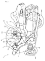
- FIG. 3 is a perspective view showing a mounting structure of the air bag module 20.
- the air bag module 20 has a casing 23, and the right and left supporting stays 21R and 21L are welded to the casing 23 at its lower portion. Further, a plurality of supporting members 30 (not shown), 31, and 32 are welded to the upper tubes 2R and 2L, and the supporting stays 21 R and 21 L are fixed to the supporting members 30, 31, and 32 by given bolts.
- a connector 25 is provided on the front surface of the casing 23, so as to input an ignition signal to the inflator accommodated in the casing 23.
- the casing 23 is covered by a substantially rectangular module cover 22 adapted to be pivotably opened about its front side at the time of inflation of the air bag 50.
- An air cleaner box 60 for cleaning the outside air to be introduced into the engine 15 and the upper cover 41 of the air cleaner box 60 is located so as to be interposed between the upper tubes 2R and 2L, and a substantially flat box-shaped audio unit 40 is located above the air cleaner box 60.
- a third supporting stay 33 is connected between the casing 23 and the upper tube 2L. Fixed to the third supporting stay 33 are an FI unit supporting stay 34 for fixing a fuel injection control (FI) unit (not shown) and a left air duct 42L for introducing the outside air into the air cleaner box 60 from a front side of a vehicle. Further, the rear surface of the casing 23 opposed to the rider is formed with a pair of slits 24 for passing the supporting belts 51.
- FI fuel injection control
- the space below the air bag module 20 as formed as the result of the optimum location of the air bag module 20 can be effectively used as an installation space for other components, so that the volume of the installation space for the air bag module 20 can be reduced.
- the audio unit 40 and an upper cover 41 of the air cleaner box 60 can be removed from the left front side of the vehicle without displacing or removing the air bag module 20. Accordingly, the maintenance of the air cleaner box 60 including the replacement of a substantially flat box-shaped air filter 44 (see FIG. 4) accommodated in the air cleaner box 60 can be easily performed.
- FIG. 4 is a side view of the air cleaner box 60 according to the present invention.
- the air cleaner box 60 includes the upper cover 41 to which the left air duct 42L is connected, a lower case 43 extending downward and having a lower end portion provided with a drain hose 47, and the substantially flat box-shaped air filter 44 provided between the upper cover 41 and the lower case 43.
- the upper cover 41 and the lower case 43 are fastened together by eight fastening portions 45.
- the upper cover 41 and the lower case 43 are formed of synthetic resin having elasticity, and a packing is provided along a joining portion between the upper case 41 and the lower case 43 to seal the joining portion.
- the intake temperature sensor is provided on an upper surface of the upper case 41.
- the mounting screw retainer structure according to the present invention is applied to each fastening portion 45 for fastening the upper cover 41 and the lower case 43.
- FIGS. 5 and 6 are a cross section taken along the line A-A in FIG. 1.
- the air bag module 20 is supported by the right supporting stay 21 R and the left supporting stay 2 1 L (see FIG. 3) respectively fixed to the upper surfaces of the right and left upper tubes 2R and 2L.
- an air bag ECU 35 for controlling the inflating operation of the air bag 50 according to information from various sensors for measuring an impact etc. applied to the vehicle body is mounted on the right supporting stay 21 R.
- FIG. 5 shows a condition where the audio unit 40 has been removed from the state shown in FIG. 3.
- the upper cover 41 can be removed in the direction shown by an arrow after loosening a plurality of mounting screws 48 in the fastening portions 45.
- the space between the upper cover 41 and the air bag module 20 is small, and the space between the right supporting stay 21 R and the upper cover 41 enough for a worker's hand to insert is also confined, so that there is a high possibility that the worker may erroneously drop the mounting screws 48 in loosening them. If the worker has dropped the mounting screws 48, the worker must recover the mounting screws 48 from the gap between parts arranged concentratedly, causing an increase in number of working steps.
- each mounting screw 48 projects from the bottom surface of the upper cover 41 after loosening the mounting screws 48 to such a condition where the upper cover 41 can be removed, there is a possibility that the lower end of each mounting screw 48 may interfere with a corner portion 44a of the air filter 44, for example, so that the upper cover 41 may not be smoothly removed.
- the mounting screw retainer structure according to this preferred embodiment can solve these problems as shown in FIG. 6.
- FIGS. 7(a) to 7(c) are enlarged sectional views illustrating the mounting screw retainer structure according to this preferred embodiment.
- each fastening portion 45 is shown, wherein it is composed of an upper retaining portion 70 formed as a part of the upper cover 41, a lower retaining portion 73 formed as a part of the lower case 43, and the mounting screw 48 for fastening the upper retaining portion 70 and the lower retaining portion 73.
- Each mounting screw 48 used in this preferred embodiment is a tapping screw capable of tapping by itself.
- FIG. 7(a) shows a condition where the mounting screw 48 is tightened to fasten the upper and lower retaining portions 70 and 73.
- the upper retaining portion 70 has an upper screw hole 71
- the lower retaining portion 73 has a lower screw hole 74.
- the upper screw hole 71 is larger in diameter than the lower screw hole 74.
- the lower screw hole 74 has a diameter slightly smaller than the diameter of the threaded portion of the mounting screw 48, so as to allow the tapping with the threaded portion of the mounting screw 48.
- the mounting screw retainer structure according to this preferred embodiment is characterized in that the upper retaining portion 70 has a cylindrical guide formed around the upper screw hole 71 so as to allow the head portion of the mounting screw 48 to move upward along the inner wall of this cylindrical guide and that a projection 72 is formed on the inner wall of this cylindrical guide.
- FIG. 7(b) shows a condition where the mounting screw 48 is loosened to a predetermined position.
- the projection 72 is formed at such a position that when the mounting screw 48 is loosened to this position where the threaded portion of the mounting screw 48 is disengaged from the internal thread of the lower screw hole 74, the head portion of the mounting screw 48 has passed through the projection 72 and the outer circumference of the head portion comes into engagement with the projection 72. Accordingly, even when the upper and lower retaining portions 70 and 73 are brought into separation from each other as shown in FIG. 7(c), there is no possibility that the mounting screw 48 may fall down from the upper retaining portion 70.
- the amount of projection of a lower end portion 48a of the mounting screw 48 from the lower surface of the upper retaining portion 70 is slight as shown in FIG. 7(c). Accordingly, in removing the upper cover 41 of the air cleaner box 60 as shown in FIG. 5, there is no possibility that the lower end portion 48a of each mounting screw 48 may interfere with the corner portion 44a of the air filter 44, thereby realizing a smooth removal/attachment operation for the upper cover 41.
- the projection 72 is a ringlike projection continuously formed on the inner wall of the cylindrical guide of the upper retaining portion 70 in this preferred embodiment, the projection 72 may be formed as a plurality of discrete projections arranged along an inner circumference on the inner wall of the cylindrical guide of the upper retaining portion 70.
- the cylindrical guide of the upper retaining portion 70 is tapered at its upper portion toward the upper end thereof, so that even when the upper opening of the cylindrical guide of the upper retaining portion 70 is directed downward in the condition where the head portion of the mounting screw 48 is retained by the projection 72, the escape of the mounting screw 48 from the upper retaining portion 70 can be reliably prevented.
- the upper cover 41 is formed of synthetic resin having elasticity, so that the upper retaining portion 70 as a part of the upper cover 41 is formed of synthetic resin having elasticity. Accordingly, by elastically deforming the upper opening of the upper retaining portion 70, the mounting screw 48 can be arbitrarily removed from the upper retaining portion 70. Additionally, the lower end portion 48a of the mounting screw slightly projecting from the lower surface of the upper retaining portion 70 as shown in FIG. 7(c) has a function of facilitating the positioning of the upper retaining portion 70 in remounting the upper cover 41 onto the lower case 43, thereby contributing to a reduction in number of working steps.
- the shapes or the like of the projections, the fastening portions, and the mounting screws are not limited to those shown in this preferred embodiment, but various modifications may be made. Further, the application of the mounting screw retainer structure according to the present invention is not limited to the air cleaner box as in this preferred embodiment, but this retainer structure is widely applicable to various components.
Abstract
Description
- The present invention relates to a mounting screw retainer structure, and more particularly to a mounting screw retainer structure which can prevent a mounting screw from falling down from a component and can also prevent the interference of the mounting screw with any other related component.
- Conventionally known as means for fastening vertically separate components such as an air cleaner box and its cover is the use of a screw, wing nut, band, etc.
- Described in
Patent Document 1 is means for fastening vertically separate cases constituting an air cleaner box, wherein an elongated bolt is connected to the lower case and the upper end of the bolt inserted through the upper case is tightened by a wing nut. Further, described inPatent Document 2 is means using a detachable one-touch fastener or the like for fastening a pleated main filter and a flexible high-porous prefilter in an air cleaner. - However, in such a layout that any other related component is arranged close to the air cleaner box and that the upper space above the air cleaner box is especially narrow, there is a problem such that a screw or the like for fastening the air cleaner box and its cover may erroneously fall down in removing the cover. There is another problem such that if the screw retained by the cover projects therefrom, the screw may interfere with any other related component in removing the cover, causing an increase in number of working steps. Neither suggestion nor consideration is given with respect to these problems in
Patent Documents - It is accordingly an object of the present invention to provide a mounting screw retainer structure which can prevent a mounting screw from falling down from a component and can also prevent the interference of the mounting screw with any other related component.
- As the first characteristics, in order to attain the above mentioned object, according to the present invention, there is provided a retainer structure for a mounting screw for fastening separate cases, characterized in that one of the separate cases is formed with a screw hole and a guide communicating with the upper end of the screw hole, that the guide has an inner diameter equal to or slightly larger than the diameter of a head portion of the mounting screw, that a projection is formed on the inner wall of the guide at an upper portion thereof, and that the distance between the projection and the lower end of the screw hole is slightly smaller than the length of a threaded portion of the mounting screw.
- Further, as the second characteristics, the projection retains the head portion of the mounting screw in a loosened condition of the mounting screw, and the upper portion of the guide is tapered so that it has an inner diameter slightly smaller than the diameter of the head portion of the mounting screw.
- Further, as the third characteristics, the separate cases include a cover and a case constituting an air cleaner box.
- Further, as the fourth characteristics, the air cleaner box is located in a narrow space below an air bag module.
- According to the invention as defined in
claim 1, the mounting screw retainer structure having the projection for retaining the mounting screw in the loosened condition of the mounting screw can be obtained with a simple configuration. Further, the amount of projection of the threaded portion of the mounting screw from the lower end of the screw hole in the loosened condition of the mounting screw is small, so that the lower end portion of the mounting screw does not interfere with any other related component. Accordingly, the number of working steps in removing one of the separate cases from the other or remounting the former to the latter can be reduced. - According to the invention as defined in
claim 2, the mounting screw does not fall down even when one of the separate cases is turned upside down in the loosened condition of the mounting screw. - According to the invention as defined in
claim 3, the cover as one of the separate cases can be easily removed and remounted in the air cleaner box whose installation space is narrow. - According to the invention as defined in
claim 4, the cover of the air cleaner box can be easily removed and remounted in such a layout that an air bag module is installed in a motorcycle and that the air cleaner box is located in a narrow space below the air bag module. - FIG. 1 is a general illustration of a motorcycle using a mounting screw retainer structure according to a preferred embodiment of the present invention.
- FIG. 2 is a perspective illustration of the motorcycle according to an embodiment of the present invention.
- FIG. 3 is a perspective view showing a mounting structure of an air bag module according to an embodiment of the present invention.
- FIG. 4 is a side view of an air cleaner box according to an embodiment of the present invention.
- FIG. 5 is a cross section taken along the line A-A in FIG. 1.
- FIG. 6 is an illustration similar to FIG. 5, showing a process of removing an upper cover after the condition shown in FIG. 5.
- FIG. 7 is an enlarged sectional views illustrating the mounting screw retainer structure according to an embodiment of the present invention.
- A preferred embodiment of the present invention will now be described in detail with reference to the drawings. FIG. 1 is a general side view of a
motorcycle 1 according to a preferred embodiment of the present invention. Themotorcycle 1 has aframe 2 composed mainly of ahead pipe 3 and a pair of right and leftupper tubes upper tube 2R being shown in FIG. 3) extending rearward from thehead pipe 3 so as to be inclined down toward the rear end of the vehicle. A pair oflower tubes 4 extend downward from theupper tubes head pipe 3, and anengine 15 as a driving source is fixedly hung from the lower ends of thelower tubes 4. A pair of right andleft front forks 7 steerable by ahandle 4 are pivotably mounted through alower bracket 6 to thehead pipe 3, and a front wheel WF is rotatably supported through its axle to the lower ends of thefront forks 7. Aseat frame 5 for supporting amain seat 10 and arear seat 11 is connected to a rear portion of theframe 2. Further, a swing arm (not shown) is pivotably connected to theframe 2, and a rear wheel WR as a drive wheel is rotatably supported through its axle to the rear ends of the swing arm. - The
motorcycle 1 according to this preferred embodiment is provided with anair bag 50 adapted to be inflated into a substantially spherical shape having such a size as to cover the upper side of themain seat 10 and to touch ameter case 36 and the vicinity of awindscreen 9 provided at the upper end of anupper cowl 8 in the event that an impact greater in level than a predetermined value is applied to the vehicle body. Anair bag module 20 including theair bag 50 and an inflator (not shown) for generating a gas for inflating theair bag 50 is fixed through a pair of supportingstays 21 to theupper tubes main seat 10 in the longitudinal direction of the vehicle. These fixed positions of theair bag module 20 are set between a meter cover (not shown) located above thehead pipe 3 and themain seat 10. - The inflation of the
air bag 50 is performed in this manner. The gas generated from the inflator is instantaneously supplied to theair bag 50 folded in theair bag module 20. As a result, a plurality of weak portions formed on three side surfaces of theair bag module 20 having a boxlike shape are broken by the pressure of this gas supplied to theair bag 50, thereby inflating theair bag 50. A pair of supportingbelts 51 are connected at their upper ends to a rear portion of theair bag 50, so as to keep theair bag 50 at a proper position in restraining the rider. The lower ends of the supportingbelts 51 are firmly secured to a vehicle body member at a position below themain seat 10. - FIG. 2 is a perspective view of the
motorcycle 1 at the time theair bag 50 is inflated. The rear surface of theair bag 50 in its inflated condition as opposed to the rider is formed as a substantially V-shaped surface as viewed in plan, so as to effectively embrace the rider. Theair bag 50 in its inflated condition is supported not only by the supportingbelts 51, but also by the whole of members located below front and lower portions of theair bag 50, including thehandle 4 and themeter case 36. Further, the right and left side surfaces of theair bag 50 at its upper portion are formed with a pair of vent holes 56 (e.g., φ 45) for discharging the gas from theair bag 50 at a proper speed under the condition where the rider is being restrained by theair bag 50. - FIG. 3 is a perspective view showing a mounting structure of the
air bag module 20. In FIG. 3, the same reference numerals as those shown in FIGS. 1 and 2 denote the same or like parts. Theair bag module 20 has acasing 23, and the right and left supportingstays casing 23 at its lower portion. Further, a plurality of supporting members 30 (not shown), 31, and 32 are welded to theupper tubes stays members connector 25 is provided on the front surface of thecasing 23, so as to input an ignition signal to the inflator accommodated in thecasing 23. Thecasing 23 is covered by a substantiallyrectangular module cover 22 adapted to be pivotably opened about its front side at the time of inflation of theair bag 50. - An
air cleaner box 60 for cleaning the outside air to be introduced into theengine 15 and theupper cover 41 of theair cleaner box 60 is located so as to be interposed between theupper tubes shaped audio unit 40 is located above theair cleaner box 60. A third supportingstay 33 is connected between thecasing 23 and theupper tube 2L. Fixed to the third supportingstay 33 are an FIunit supporting stay 34 for fixing a fuel injection control (FI) unit (not shown) and aleft air duct 42L for introducing the outside air into theair cleaner box 60 from a front side of a vehicle. Further, the rear surface of thecasing 23 opposed to the rider is formed with a pair ofslits 24 for passing the supportingbelts 51. - According to the mounting structure of the
air bag module 20, the space below theair bag module 20 as formed as the result of the optimum location of theair bag module 20 can be effectively used as an installation space for other components, so that the volume of the installation space for theair bag module 20 can be reduced. Further, by removing the FIunit supporting stay 34 and the third supportingstay 33 in the mounted condition shown in FIG. 3, theaudio unit 40 and anupper cover 41 of theair cleaner box 60 can be removed from the left front side of the vehicle without displacing or removing theair bag module 20. Accordingly, the maintenance of theair cleaner box 60 including the replacement of a substantially flat box-shaped air filter 44 (see FIG. 4) accommodated in theair cleaner box 60 can be easily performed. - FIG. 4 is a side view of the
air cleaner box 60 according to the present invention. In FIG. 4, the same reference numerals as those shown in FIGS. 1 to 3 denote the same or like parts. Theair cleaner box 60 includes theupper cover 41 to which theleft air duct 42L is connected, alower case 43 extending downward and having a lower end portion provided with adrain hose 47, and the substantially flat box-shaped air filter 44 provided between theupper cover 41 and thelower case 43. Theupper cover 41 and thelower case 43 are fastened together by eight fasteningportions 45. Theupper cover 41 and thelower case 43 are formed of synthetic resin having elasticity, and a packing is provided along a joining portion between theupper case 41 and thelower case 43 to seal the joining portion. Further, the intake temperature sensor is provided on an upper surface of theupper case 41. The mounting screw retainer structure according to the present invention is applied to eachfastening portion 45 for fastening theupper cover 41 and thelower case 43. - FIGS. 5 and 6 are a cross section taken along the line A-A in FIG. 1. In FIGS. 5 and 6, the same reference numerals as those shown in FIGS. 1 to 4 denote the same or like parts. As mentioned above, the
air bag module 20 is supported by theright supporting stay 21 R and theleft supporting stay 2 1 L (see FIG. 3) respectively fixed to the upper surfaces of the right and leftupper tubes air bag ECU 35 for controlling the inflating operation of theair bag 50 according to information from various sensors for measuring an impact etc. applied to the vehicle body is mounted on theright supporting stay 21 R. - FIG. 5 shows a condition where the
audio unit 40 has been removed from the state shown in FIG. 3. In this condition, theupper cover 41 can be removed in the direction shown by an arrow after loosening a plurality of mountingscrews 48 in thefastening portions 45. However, the space between theupper cover 41 and theair bag module 20 is small, and the space between theright supporting stay 21 R and theupper cover 41 enough for a worker's hand to insert is also confined, so that there is a high possibility that the worker may erroneously drop the mounting screws 48 in loosening them. If the worker has dropped the mountingscrews 48, the worker must recover the mounting screws 48 from the gap between parts arranged concentratedly, causing an increase in number of working steps. Further, if the lower end of each mountingscrew 48 projects from the bottom surface of theupper cover 41 after loosening the mountingscrews 48 to such a condition where theupper cover 41 can be removed, there is a possibility that the lower end of each mountingscrew 48 may interfere with acorner portion 44a of theair filter 44, for example, so that theupper cover 41 may not be smoothly removed. The mounting screw retainer structure according to this preferred embodiment can solve these problems as shown in FIG. 6. - FIGS. 7(a) to 7(c) are enlarged sectional views illustrating the mounting screw retainer structure according to this preferred embodiment. In FIGS. 7(a) to 7(c), each
fastening portion 45 is shown, wherein it is composed of anupper retaining portion 70 formed as a part of theupper cover 41, alower retaining portion 73 formed as a part of thelower case 43, and the mountingscrew 48 for fastening the upper retainingportion 70 and thelower retaining portion 73. Each mountingscrew 48 used in this preferred embodiment is a tapping screw capable of tapping by itself. - FIG. 7(a) shows a condition where the mounting
screw 48 is tightened to fasten the upper andlower retaining portions upper retaining portion 70 has anupper screw hole 71, and thelower retaining portion 73 has alower screw hole 74. Theupper screw hole 71 is larger in diameter than thelower screw hole 74. Thelower screw hole 74 has a diameter slightly smaller than the diameter of the threaded portion of the mountingscrew 48, so as to allow the tapping with the threaded portion of the mountingscrew 48. Accordingly, the threaded portion of the mountingscrew 48 is loosely inserted through theupper screw hole 71, and a tightening force for fastening the upper andlower retaining portions lower screw hole 74 and the head portion of the mountingscrew 48. The mounting screw retainer structure according to this preferred embodiment is characterized in that the upper retainingportion 70 has a cylindrical guide formed around theupper screw hole 71 so as to allow the head portion of the mountingscrew 48 to move upward along the inner wall of this cylindrical guide and that aprojection 72 is formed on the inner wall of this cylindrical guide. - FIG. 7(b) shows a condition where the mounting
screw 48 is loosened to a predetermined position. Theprojection 72 is formed at such a position that when the mountingscrew 48 is loosened to this position where the threaded portion of the mountingscrew 48 is disengaged from the internal thread of thelower screw hole 74, the head portion of the mountingscrew 48 has passed through theprojection 72 and the outer circumference of the head portion comes into engagement with theprojection 72. Accordingly, even when the upper andlower retaining portions screw 48 may fall down from the upper retainingportion 70. Furthermore, the amount of projection of alower end portion 48a of the mountingscrew 48 from the lower surface of the upper retainingportion 70 is slight as shown in FIG. 7(c). Accordingly, in removing theupper cover 41 of theair cleaner box 60 as shown in FIG. 5, there is no possibility that thelower end portion 48a of each mountingscrew 48 may interfere with thecorner portion 44a of theair filter 44, thereby realizing a smooth removal/attachment operation for theupper cover 41. - While the
projection 72 is a ringlike projection continuously formed on the inner wall of the cylindrical guide of the upper retainingportion 70 in this preferred embodiment, theprojection 72 may be formed as a plurality of discrete projections arranged along an inner circumference on the inner wall of the cylindrical guide of the upper retainingportion 70. Further, the cylindrical guide of the upper retainingportion 70 is tapered at its upper portion toward the upper end thereof, so that even when the upper opening of the cylindrical guide of the upper retainingportion 70 is directed downward in the condition where the head portion of the mountingscrew 48 is retained by theprojection 72, the escape of the mountingscrew 48 from the upper retainingportion 70 can be reliably prevented. - As mentioned above, the
upper cover 41 is formed of synthetic resin having elasticity, so that the upper retainingportion 70 as a part of theupper cover 41 is formed of synthetic resin having elasticity. Accordingly, by elastically deforming the upper opening of the upper retainingportion 70, the mountingscrew 48 can be arbitrarily removed from the upper retainingportion 70. Additionally, thelower end portion 48a of the mounting screw slightly projecting from the lower surface of the upper retainingportion 70 as shown in FIG. 7(c) has a function of facilitating the positioning of the upper retainingportion 70 in remounting theupper cover 41 onto thelower case 43, thereby contributing to a reduction in number of working steps. - The shapes or the like of the projections, the fastening portions, and the mounting screws are not limited to those shown in this preferred embodiment, but various modifications may be made. Further, the application of the mounting screw retainer structure according to the present invention is not limited to the air cleaner box as in this preferred embodiment, but this retainer structure is widely applicable to various components.
- 41: upper cover 43: lower case 45: fastening portion 48: mounting
screw 48a: lower end portion of the mounting screw 60: air cleaner box 70: upper retaining portion 71: upper screw hole 72: projection for retaining the head portion of the mounting screw 73: lower retaining portion 74: lower screw hole
Claims (4)
- A retainer structure for a mounting screw (48) for fastening separate cases,
characterized in that
one of said separate cases is formed with a screw hole and a guide communicating with the upper end of said screw hole, that said guide has an inner diameter equal to or slightly larger than the diameter of a head portion of said mounting screw (48), that a projection is formed on the inner wall of said guide at an upper portion thereof, and that the distance between said projection and the lower end of said screw hole is slightly smaller than the length of a threaded portion of said mounting screw (48). - The retainer structure according to claim 1,
wherein said projection retains the head portion of said mounting screw (72) in a loosened condition of said mounting screw (48), and
the upper portion of said guide is tapered so that it has an inner diameter slightly smaller than the diameter of the head portion of said mounting screw (48). - The retainer structure according to claim 1 or 2, wherein said separate cases comprise a cover and a case constituting an air cleaner box (60).
- The retainer structure according to any of the preceding claims, wherein said air cleaner box (60) is located in a narrow space below an air bag module.
Applications Claiming Priority (1)
| Application Number | Priority Date | Filing Date | Title |
|---|---|---|---|
| JP2005260084A JP2007071321A (en) | 2005-09-08 | 2005-09-08 | Mounting screw retention structure |
Publications (2)
| Publication Number | Publication Date |
|---|---|
| EP1762731A1 true EP1762731A1 (en) | 2007-03-14 |
| EP1762731B1 EP1762731B1 (en) | 2008-06-25 |
Family
ID=37189137
Family Applications (1)
| Application Number | Title | Priority Date | Filing Date |
|---|---|---|---|
| EP06016116A Expired - Fee Related EP1762731B1 (en) | 2005-09-08 | 2006-08-02 | Mounting screw retainer structure |
Country Status (5)
| Country | Link |
|---|---|
| EP (1) | EP1762731B1 (en) |
| JP (1) | JP2007071321A (en) |
| BR (1) | BRPI0603756A (en) |
| CA (1) | CA2556252C (en) |
| DE (1) | DE602006001556D1 (en) |
Cited By (3)
| Publication number | Priority date | Publication date | Assignee | Title |
|---|---|---|---|---|
| GB2509961A (en) * | 2013-01-20 | 2014-07-23 | Deep Thought Ltd | Fastener retention system for product mounting |
| CN104132041A (en) * | 2014-07-11 | 2014-11-05 | 山东鲁帆集团有限公司 | Torsional shearing bolt assembly, use method thereof and construction steel structure with torsional shearing bolt assembly |
| FR3061522A1 (en) * | 2017-01-05 | 2018-07-06 | Peugeot Citroen Automobiles Sa. | INTERNAL COMBUSTION ENGINE AIR FILTER |
Families Citing this family (1)
| Publication number | Priority date | Publication date | Assignee | Title |
|---|---|---|---|---|
| JP5155073B2 (en) * | 2008-09-05 | 2013-02-27 | ヤマハ発動機株式会社 | Screw holding structure and vehicle |
Citations (4)
| Publication number | Priority date | Publication date | Assignee | Title |
|---|---|---|---|---|
| DE8701553U1 (en) * | 1987-02-02 | 1987-03-19 | Julius & August Erbsloeh Gmbh + Co, 5620 Velbert, De | |
| JPS63210463A (en) * | 1987-02-20 | 1988-09-01 | Yamaha Motor Co Ltd | Cover fitting structure for article storage box |
| DE8708965U1 (en) * | 1987-06-29 | 1988-10-27 | Robert Bosch Gmbh, 7000 Stuttgart, De | |
| US6419192B1 (en) * | 1996-11-25 | 2002-07-16 | Ejot Kunststofftechnik Gmbh & Co. Kg | Retaining element and method of mounting lines |
Family Cites Families (7)
| Publication number | Priority date | Publication date | Assignee | Title |
|---|---|---|---|---|
| JPS5999169U (en) * | 1982-09-02 | 1984-07-04 | 本田技研工業株式会社 | Air cleaner case for motorcycles |
| JPS59113509U (en) * | 1983-01-20 | 1984-07-31 | 株式会社富士通ゼネラル | Screw prevention structure |
| DE8410539U1 (en) * | 1984-04-04 | 1985-05-02 | Marker Patentverwertungsgesellschaft mbH, Baar | Device on components that can be screwed onto an object |
| JPS6449715U (en) * | 1987-09-22 | 1989-03-28 | ||
| JPH0312607U (en) * | 1989-06-23 | 1991-02-08 | ||
| JP2000079250A (en) * | 1999-10-06 | 2000-03-21 | Toyomaru Sangyo Kk | Electronic control circuit board protective cover |
| JP4121112B2 (en) * | 2002-03-27 | 2008-07-23 | 本田技研工業株式会社 | Airbag device |
-
2005
- 2005-09-08 JP JP2005260084A patent/JP2007071321A/en active Pending
-
2006
- 2006-08-02 DE DE602006001556T patent/DE602006001556D1/en active Active
- 2006-08-02 EP EP06016116A patent/EP1762731B1/en not_active Expired - Fee Related
- 2006-08-16 CA CA002556252A patent/CA2556252C/en not_active Expired - Fee Related
- 2006-09-05 BR BRPI0603756-9A patent/BRPI0603756A/en not_active Application Discontinuation
Patent Citations (4)
| Publication number | Priority date | Publication date | Assignee | Title |
|---|---|---|---|---|
| DE8701553U1 (en) * | 1987-02-02 | 1987-03-19 | Julius & August Erbsloeh Gmbh + Co, 5620 Velbert, De | |
| JPS63210463A (en) * | 1987-02-20 | 1988-09-01 | Yamaha Motor Co Ltd | Cover fitting structure for article storage box |
| DE8708965U1 (en) * | 1987-06-29 | 1988-10-27 | Robert Bosch Gmbh, 7000 Stuttgart, De | |
| US6419192B1 (en) * | 1996-11-25 | 2002-07-16 | Ejot Kunststofftechnik Gmbh & Co. Kg | Retaining element and method of mounting lines |
Cited By (5)
| Publication number | Priority date | Publication date | Assignee | Title |
|---|---|---|---|---|
| GB2509961A (en) * | 2013-01-20 | 2014-07-23 | Deep Thought Ltd | Fastener retention system for product mounting |
| GB2509961B (en) * | 2013-01-20 | 2015-07-15 | Deep Thought Ltd | Fastener retention system for product mounting |
| CN104132041A (en) * | 2014-07-11 | 2014-11-05 | 山东鲁帆集团有限公司 | Torsional shearing bolt assembly, use method thereof and construction steel structure with torsional shearing bolt assembly |
| CN104132041B (en) * | 2014-07-11 | 2016-09-07 | 山东鲁帆集团有限公司 | Turn round and cut bolt assembly, using method and apply the construction steel structure of this assembly |
| FR3061522A1 (en) * | 2017-01-05 | 2018-07-06 | Peugeot Citroen Automobiles Sa. | INTERNAL COMBUSTION ENGINE AIR FILTER |
Also Published As
| Publication number | Publication date |
|---|---|
| BRPI0603756A (en) | 2007-04-27 |
| CA2556252C (en) | 2009-04-21 |
| EP1762731B1 (en) | 2008-06-25 |
| DE602006001556D1 (en) | 2008-08-07 |
| CA2556252A1 (en) | 2007-03-08 |
| JP2007071321A (en) | 2007-03-22 |
Similar Documents
| Publication | Publication Date | Title |
|---|---|---|
| EP1762442B1 (en) | Air bag module mounting structure | |
| US7549675B2 (en) | Straddle-type vehicle | |
| US7628835B2 (en) | Structure for holding fixing screws | |
| US11124260B2 (en) | Saddle type vehicle | |
| JP6368237B2 (en) | Saddle riding vehicle | |
| CA2556252C (en) | Mounting screw retainer structure | |
| JP6613092B2 (en) | Saddle riding vehicle | |
| US11407464B2 (en) | Front structure of saddle riding vehicle | |
| EP2399810A1 (en) | Saddle riding type vehicle | |
| JP4737529B2 (en) | Airbag support belt cover structure | |
| JP4766564B2 (en) | Motorcycle airbag device | |
| US20170284347A1 (en) | Saddle-ride type vehicle | |
| JP5364667B2 (en) | Blinker and saddle riding type vehicle equipped with the same | |
| US7789416B2 (en) | Air bag module cover structure | |
| EP1762440B1 (en) | Air bag module cover structure | |
| JP5013951B2 (en) | Electrical component arrangement structure for motorcycles | |
| US11092121B2 (en) | Saddle riding vehicle | |
| JP4642508B2 (en) | Power supply diagnostic device for vehicles | |
| JP5964681B2 (en) | Evaporative fuel supply device and motorcycle including the same | |
| CN108463401B (en) | Saddle-ride type vehicle | |
| JP2020045055A (en) | Vehicle body cover and saddle-riding type vehicle | |
| US11199166B2 (en) | Saddle riding vehicle | |
| JP2009107570A (en) | Saddle-ride type vehicle | |
| JP2001041060A (en) | Throttle operating device of saddle riding type vehicle | |
| JP2009035186A (en) | Tractor |
Legal Events
| Date | Code | Title | Description |
|---|---|---|---|
| PUAI | Public reference made under article 153(3) epc to a published international application that has entered the european phase |
Free format text: ORIGINAL CODE: 0009012 |
|
| 17P | Request for examination filed |
Effective date: 20060802 |
|
| AK | Designated contracting states |
Kind code of ref document: A1 Designated state(s): AT BE BG CH CY CZ DE DK EE ES FI FR GB GR HU IE IS IT LI LT LU LV MC NL PL PT RO SE SI SK TR |
|
| AX | Request for extension of the european patent |
Extension state: AL BA HR MK YU |
|
| 17Q | First examination report despatched |
Effective date: 20070425 |
|
| AKX | Designation fees paid |
Designated state(s): DE FR IT |
|
| GRAP | Despatch of communication of intention to grant a patent |
Free format text: ORIGINAL CODE: EPIDOSNIGR1 |
|
| GRAS | Grant fee paid |
Free format text: ORIGINAL CODE: EPIDOSNIGR3 |
|
| GRAA | (expected) grant |
Free format text: ORIGINAL CODE: 0009210 |
|
| AK | Designated contracting states |
Kind code of ref document: B1 Designated state(s): DE FR IT |
|
| REF | Corresponds to: |
Ref document number: 602006001556 Country of ref document: DE Date of ref document: 20080807 Kind code of ref document: P |
|
| PLBE | No opposition filed within time limit |
Free format text: ORIGINAL CODE: 0009261 |
|
| STAA | Information on the status of an ep patent application or granted ep patent |
Free format text: STATUS: NO OPPOSITION FILED WITHIN TIME LIMIT |
|
| 26N | No opposition filed |
Effective date: 20090326 |
|
| REG | Reference to a national code |
Ref country code: DE Ref legal event code: R084 Ref document number: 602006001556 Country of ref document: DE Effective date: 20120523 Ref country code: DE Ref legal event code: R084 Ref document number: 602006001556 Country of ref document: DE Effective date: 20120621 |
|
| PGFP | Annual fee paid to national office [announced via postgrant information from national office to epo] |
Ref country code: FR Payment date: 20130808 Year of fee payment: 8 |
|
| REG | Reference to a national code |
Ref country code: FR Ref legal event code: ST Effective date: 20150430 |
|
| PG25 | Lapsed in a contracting state [announced via postgrant information from national office to epo] |
Ref country code: FR Free format text: LAPSE BECAUSE OF NON-PAYMENT OF DUE FEES Effective date: 20140901 |
|
| PGFP | Annual fee paid to national office [announced via postgrant information from national office to epo] |
Ref country code: DE Payment date: 20170725 Year of fee payment: 12 Ref country code: IT Payment date: 20170824 Year of fee payment: 12 |
|
| REG | Reference to a national code |
Ref country code: DE Ref legal event code: R119 Ref document number: 602006001556 Country of ref document: DE |
|
| PG25 | Lapsed in a contracting state [announced via postgrant information from national office to epo] |
Ref country code: DE Free format text: LAPSE BECAUSE OF NON-PAYMENT OF DUE FEES Effective date: 20190301 Ref country code: IT Free format text: LAPSE BECAUSE OF NON-PAYMENT OF DUE FEES Effective date: 20180802 |