EP1762730B1 - Mitrejoinersystem - Google Patents
Mitrejoinersystem Download PDFInfo
- Publication number
- EP1762730B1 EP1762730B1 EP20060018513 EP06018513A EP1762730B1 EP 1762730 B1 EP1762730 B1 EP 1762730B1 EP 20060018513 EP20060018513 EP 20060018513 EP 06018513 A EP06018513 A EP 06018513A EP 1762730 B1 EP1762730 B1 EP 1762730B1
- Authority
- EP
- European Patent Office
- Prior art keywords
- mitre
- channel
- piece
- counterbearing
- sleeve
- Prior art date
- Legal status (The legal status is an assumption and is not a legal conclusion. Google has not performed a legal analysis and makes no representation as to the accuracy of the status listed.)
- Active
Links
- 238000005553 drilling Methods 0.000 claims description 8
- 235000000857 Pentadesma butyracea Nutrition 0.000 description 1
- 240000002134 Pentadesma butyracea Species 0.000 description 1
- 238000003780 insertion Methods 0.000 description 1
- 230000037431 insertion Effects 0.000 description 1
- 230000013011 mating Effects 0.000 description 1
Images


Classifications
-
- F—MECHANICAL ENGINEERING; LIGHTING; HEATING; WEAPONS; BLASTING
- F16—ENGINEERING ELEMENTS AND UNITS; GENERAL MEASURES FOR PRODUCING AND MAINTAINING EFFECTIVE FUNCTIONING OF MACHINES OR INSTALLATIONS; THERMAL INSULATION IN GENERAL
- F16B—DEVICES FOR FASTENING OR SECURING CONSTRUCTIONAL ELEMENTS OR MACHINE PARTS TOGETHER, e.g. NAILS, BOLTS, CIRCLIPS, CLAMPS, CLIPS OR WEDGES; JOINTS OR JOINTING
- F16B7/00—Connections of rods or tubes, e.g. of non-circular section, mutually, including resilient connections
- F16B7/18—Connections of rods or tubes, e.g. of non-circular section, mutually, including resilient connections using screw-thread elements
- F16B7/187—Connections of rods or tubes, e.g. of non-circular section, mutually, including resilient connections using screw-thread elements with sliding nuts or other additional connecting members for joining profiles provided with grooves or channels
-
- F—MECHANICAL ENGINEERING; LIGHTING; HEATING; WEAPONS; BLASTING
- F16—ENGINEERING ELEMENTS AND UNITS; GENERAL MEASURES FOR PRODUCING AND MAINTAINING EFFECTIVE FUNCTIONING OF MACHINES OR INSTALLATIONS; THERMAL INSULATION IN GENERAL
- F16B—DEVICES FOR FASTENING OR SECURING CONSTRUCTIONAL ELEMENTS OR MACHINE PARTS TOGETHER, e.g. NAILS, BOLTS, CIRCLIPS, CLAMPS, CLIPS OR WEDGES; JOINTS OR JOINTING
- F16B12/00—Jointing of furniture or the like, e.g. hidden from exterior
- F16B12/10—Jointing of furniture or the like, e.g. hidden from exterior using pegs, bolts, tenons, clamps, clips, or the like
- F16B12/12—Jointing of furniture or the like, e.g. hidden from exterior using pegs, bolts, tenons, clamps, clips, or the like for non-metal furniture parts, e.g. made of wood, of plastics
- F16B12/20—Jointing of furniture or the like, e.g. hidden from exterior using pegs, bolts, tenons, clamps, clips, or the like for non-metal furniture parts, e.g. made of wood, of plastics using clamps, clips, wedges, sliding bolts, or the like
- F16B12/2009—Jointing of furniture or the like, e.g. hidden from exterior using pegs, bolts, tenons, clamps, clips, or the like for non-metal furniture parts, e.g. made of wood, of plastics using clamps, clips, wedges, sliding bolts, or the like actuated by rotary motion
- F16B12/2054—Jointing of furniture or the like, e.g. hidden from exterior using pegs, bolts, tenons, clamps, clips, or the like for non-metal furniture parts, e.g. made of wood, of plastics using clamps, clips, wedges, sliding bolts, or the like actuated by rotary motion with engaging screw threads as securing means for limiting movement
- F16B12/2063—Jointing of furniture or the like, e.g. hidden from exterior using pegs, bolts, tenons, clamps, clips, or the like for non-metal furniture parts, e.g. made of wood, of plastics using clamps, clips, wedges, sliding bolts, or the like actuated by rotary motion with engaging screw threads as securing means for limiting movement with engaging screw threads as tightening means
Definitions
- the invention relates to a miter connector system with first and second profile bars, of which at least one has an open or closed, but if necessary openable longitudinal groove, with a connecting piece which has an external thread at one end and is inserted into a first channel which is transverse to at least one of the two mutually contacting surfaces of the mitered first and second profile bars extends, wherein the external thread is screwed into the inserted in the second profile bar first abutment piece and the opposite end is provided with a recess such that this recess in a second in one to the first channel transverse channel insertable abutment piece is inserted, which has an internal thread for receiving a screw whose front end is in engagement with the recess.
- Miterssverbindersystem is in the DE 94 15 356.6 U1 described.
- miter connectors known.
- Kanya distributes miter joints that are intended to connect a mitered section bar to one side of a section bar provided with an undercut groove.
- This miter connector consists of a bent anchor head, for example, with an angle of 15 °, 30 ° or 45 °, in left and right versions.
- the anchor head is formed half-lenticular and engages behind the undercut groove, while the opposite end engage in an abutment piece and can be fixed there.
- the abutment piece is tubular and is in one used in the groove area transverse to the longitudinal direction of the profile bar hole.
- the invention is therefore an object of the invention to provide a miter connection system of the type mentioned, which always allows a technically simple means a secure and fixed miter connection of two profile bars.
- the first channel penetrates both mitered end faces of the profile bars and the first abutment piece is sleeve-shaped with a transverse to the longitudinal axis of the sleeve thread for receiving the external thread, and that the external thread to Training a contact surface is removed, with which a screwed into the first abutment piece fixing screw is brought into contact.
- the respective end faces of the profile bars to be joined are mitred, it is advantageous if the first channel penetrates both miter-cut end faces of the profile bars and the first abutment piece sleeve-shaped is formed with a transverse to the sleeve longitudinal axis thread for receiving the external thread. So that the externally threaded end of the connecting piece can be better fixed, it is furthermore advantageous if the external thread is removed to form a contact surface with which a fixing screw which can be screwed into the first abutment piece can be brought into contact.
- the connecting piece between the external thread and the recess has a constriction.
- the connector has a mark which is arranged in the longitudinal direction approximately in the middle.
- the first channel must be introduced into the end faces of the profiled bars substantially perpendicular to the miter cutting surface and this is manually quite complicated and partially unsuccessful and not always provided with large drills provided with tensioners, it is advantageous if a drilling jig for producing a in forms part of the Gehrungsverbindersystems approximately perpendicular to the miter surfaces extending first channel.
- the drilling jig is L-shaped
- the first leg is movable perpendicular to the second leg and has an extending in the direction of and approximately parallel to the second leg extension, which is approximately the shape and the size of the sleeve-shaped abutment pieces has, which extension is used to produce the first channel in the existing for the sleeve-shaped abutment piece in the corresponding section bar opening
- the second leg has an approximately perpendicular to the extension extending bore for guiding the first channel producing drill
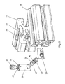
- the two described examples of a miter joint system 10 are used for connecting first and second profile bars 12 and 14.
- at least one of the profile bars 12 or 14 must have an open or closed longitudinal groove 16, wherein a closed longitudinal groove 16 then simply opened as needed can be.
- the miter connector system 10 has a connecting piece 18 which has an external thread 20 at one end and is inserted into a first channel 22, which in this case has been introduced in the first profiled bar 12 perpendicular to the miter surface of this first profiled bar 12 is.
- first channel 22 perpendicular to the miter surface of this first profiled bar 12 is.
- perpendicular means the most ideal form of positioning the first channel 22 so that it can often be said that the first channel 22 is transverse to at least one of the two mating surfaces of the mitered first and second profile bars 12 and 14 runs.
- the opposite end of the connecting piece 18 is provided with a recess 26 such that this recess 26 is inserted into a second insertable into a channel 22 extending transversely to the first channel 22 abutment piece 30.
- This second abutment piece 30 has an internal thread 32, namely for receiving a screw 34, the front end of which can be brought into engagement with the recess 26 and thus fix the connecting piece 18.
- the recess 26 is semicircular and arranged so that when screwing the screw 34, the connector 18 is subjected to train and thus the two profile bars 12 and 14 moves towards each other.
- the first abutment piece is a so-called sliding block 24 which has been inserted into the longitudinal groove 16.
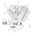
- the first channel 22 penetrates both mitred end faces of the profiled bars 12 and 14.
- the first abutment piece 24 is in this case sleeve-shaped with a transverse to the longitudinal axis of the sleeve thread 38, which serves to receive the external thread 20.
- the same components as in the first embodiment are used.
- the second profiled bar now also has a second channel 28, specifically for receiving the first abutment piece 24.
- both examples have in common that the connecting piece 18 between the external thread 20 and the recess 26 has a constriction 40. This is seen approximately in the middle in the longitudinal direction of the connecting piece 18. Also approximately in the middle of the connecting piece 18, a mark 42 is present, which serves the adjustment depth of the one end of the connecting piece 18 in the second profiled bar 14.
- the miter connector system 10 still has an additional component, namely a drilling jig 50.
- This drilling jig 50 is, as in the FIGS. 7 and 8 to be seen, L-shaped, wherein the first leg 52 is movable perpendicular to the second leg 54, so that in the direction of and approximately parallel to the second leg 54 extending extension 56 simply into the corresponding second channel 28 of the mitered profile bar 12 or 14 can be introduced.
- the two legs 52 and 54 are moved by means of a lever 60 vice like a vice relative to each other and indeed for the insertion of the profile bar 12 or 14 away from each other. Then just the second channel 28 can be pushed over the extension 56 and the two legs 52 and 54 are moved toward each other again. As a result, the corresponding end face is fixed the first leg 52 facing surface of the second leg 54 at.
- the second leg 54 has an approximately perpendicular to the extension 56 extending bore 58, which then serves to guide the first channel 22 generating drill. This ensures that each first channel 22 always runs approximately perpendicular to the end face of the mitered profile bar 12 or 14.
Landscapes
- Engineering & Computer Science (AREA)
- General Engineering & Computer Science (AREA)
- Mechanical Engineering (AREA)
- Mutual Connection Of Rods And Tubes (AREA)
- Gripping Jigs, Holding Jigs, And Positioning Jigs (AREA)
Description
Die Erfindung betrifft ein Gehrungsverbindersystem mit ersten und zweiten Profilstäben, von denen mindestens einer eine offene oder geschlossene, aber bei Bedarf zu öffnende Längsnut aufweist, mit einem Verbindungsstück, das an einem Ende ein Außengewinde aufweist und in einen ersten Kanal eingesetzt ist, der quer zu mindestens einer der beiden sich einander berührenden Flächen der auf Gehrung verbundenen ersten und zweiten Profilstäbe verläuft, wobei das Außengewinde in das im zweiten Profilstab eingesetztes erstes Widerlagerstück eingedreht ist und das entgegengesetzte Ende mit einer Aussparung versehen ist derart, dass diese Aussparung in ein zweites in einen zum ersten Kanal quer verlaufenden Kanal einsetzbares Widerlagerstück eingesetzt ist, das ein Innengewinde aufweist zur Aufnahme einer Schraube, deren vorderes Ende mit der Aussparung sich in Eingriff befindet.The invention relates to a miter connector system with first and second profile bars, of which at least one has an open or closed, but if necessary openable longitudinal groove, with a connecting piece which has an external thread at one end and is inserted into a first channel which is transverse to at least one of the two mutually contacting surfaces of the mitered first and second profile bars extends, wherein the external thread is screwed into the inserted in the second profile bar first abutment piece and the opposite end is provided with a recess such that this recess in a second in one to the first channel transverse channel insertable abutment piece is inserted, which has an internal thread for receiving a screw whose front end is in engagement with the recess.
Ein derartiges Gehrungsverbindersystem ist in der
Für sogenannte Doppelgehrungsverbindungen sind sogenannte gelenkige Ankerkopfverbindungen vorgesehen, die dann für einen Gehrungsbereich von 0-90° verwandt werden können. Bei dieser Art von sogenannter Doppelgehrungsverbindung ist, wie auch bei der Ankerkopfgehrungsverbindung, das Verbindungselement in der Längsbohrung des Profilstabes angeordnet. Auch bei dieser Doppelgehrungsverbindung werden Widerlagerstücke verwandt, die demjenigen der Ankerkopfgehrungsverbindung ähnlich sind.For so-called Doppelgehrungsverbindungen so-called articulated anchor head connections are provided, which can then be used for a miter range of 0-90 °. In this type of so-called Doppelgehrungsverbindung, as in the Ankerkopfgehrungsverbindung, the connecting element is arranged in the longitudinal bore of the profiled bar. Also in this Doppelgehrungsverbindung abutment pieces are used, which are similar to that of Ankerkopfgehrungsverbindung.
Den beschriebenen Gehrungsverbindungen ist gemein, dass für viele Anwendungsfälle die Verbindungskraft unzureichend ist.The mitred joints described have in common that for many applications, the connection force is insufficient.
Der Erfindung liegt daher die Aufgabe zugrunde, ein Gehrungsverbindungssystem der eingangs genannten Art anzugeben, das mit technisch einfachen Mitteln stets eine sichere und feste Gehrungsverbindung zweier Profilstäbe ermöglicht.The invention is therefore an object of the invention to provide a miter connection system of the type mentioned, which always allows a technically simple means a secure and fixed miter connection of two profile bars.
Diese Aufgabe wird bei einem Gehrungssystem der eingangs genannten Art erfindungsgemäß dadurch gelöst, dass der erste Kanal beide auf Gehrung geschnittene Stirnflächen der Profilstäbe durchdringt und das erste Widerlagerstück hülsenförmig ausgebildet ist mit einem quer zur Hülsenlängsachse verlaufenden Gewinde zur Aufnahme des Außengewindes, und dass das Außengewinde zur Ausbildung einer Kontaktfläche entfernt ist, mit welcher eine in das erste Widerlagerstück eingedrehte Fixierschraube in Kontakt gebracht ist. Da die jeweiligen Stirnflächen der zu verbindenden Profilstäbe auf Gehrung geschnitten sind, so ist es dabei vorteilhaft, wenn der erste Kanal beide auf Gehrung geschnittene Stirnflächen der Profilstäbe durchdringt und das erste Widerlagerstück hülsenförmig ausgebildet ist mit einem quer zur Hülsenlängsachse verlaufenden Gewinde zur Aufnahme des Außengewindes. Damit das mit dem Außengewinde versehene Ende des Verbindungsstücks besser fixiert werden kann, ist es des weiteren vorteilhaft, wenn das Außengewinde zur Ausbildung einer Kontaktfläche entfernt ist, mit welcher eine in das erste Widerlagerstück eindrehbare Fixierschraube in Kontakt bringbar ist.This object is achieved in a miter system of the type mentioned in the present invention that the first channel penetrates both mitered end faces of the profile bars and the first abutment piece is sleeve-shaped with a transverse to the longitudinal axis of the sleeve thread for receiving the external thread, and that the external thread to Training a contact surface is removed, with which a screwed into the first abutment piece fixing screw is brought into contact. Since the respective end faces of the profile bars to be joined are mitred, it is advantageous if the first channel penetrates both miter-cut end faces of the profile bars and the first abutment piece sleeve-shaped is formed with a transverse to the sleeve longitudinal axis thread for receiving the external thread. So that the externally threaded end of the connecting piece can be better fixed, it is furthermore advantageous if the external thread is removed to form a contact surface with which a fixing screw which can be screwed into the first abutment piece can be brought into contact.
Aus Gründen der Materialeinsparung ist es vorgesehen, dass das Verbindungsstück zwischen dem Außengewinde und der Aussparung eine Einschnürung aufweist.For reasons of material savings, it is provided that the connecting piece between the external thread and the recess has a constriction.
Damit einfach sichergestellt werden kann, dass das Verbindungsstück zumindest in etwa zu gleichen Teilen in die beiden Stirnflächen der zu verbindenden Profilstäbe eintaucht, ist es vorteilhaft, wenn das Verbindungsstück eine Markierung aufweist, die in Längsrichtung in etwa in der Mitte angeordnet ist.So that it can be easily ensured that the connector dips at least approximately in equal parts in the two end faces of the profile bars to be joined, it is advantageous if the connector has a mark which is arranged in the longitudinal direction approximately in the middle.
Selbstverständlich ist es möglich, die hülsenförmig ausgebildeten Widerlagerstücke in die entsprechenden Öffnungen bzw. Kanäle einzusetzen und durch aufwendiges und oftmals auch schwieriges manuelles Positionieren in die richtige Lage zur Aufnahme des Verbindungsstücks zu versetzen. Wesentlich erleichtert wird diese Positionierungsaufgabe dadurch, dass die beiden hülsenförmig ausgebildeten Widerlagerstücke an den im Gebrauchszustand zu den Außenflächen der Profilstäbe weisenden Stirnseiten Positionsanzeiger aufweisen.Of course, it is possible to use the sleeve-shaped abutment pieces in the corresponding openings or channels and to put by consuming and often difficult manual positioning in the correct position for receiving the connector. This positioning task is considerably facilitated by the fact that the two sleeve-shaped abutment pieces have position indicators on the end faces pointing in the use state to the outer surfaces of the profiled bars.
Da der erste Kanal nach Möglichkeit im wesentlichen senkrecht zur Gehrungsschnittfläche in die Stirnseiten der Profilstäbe eingebracht werden muss und dies manuell recht aufwendig und teilweise erfolglos ist sowie nicht immer große mit Spannvorrichtungen versehene Bohrmaschinen vorhanden sind, ist es vorteilhaft, wenn eine Bohrlehre zur Herstellung eines in etwa senkrecht zu den Gehrungsflächen verlaufenden ersten Kanals ein Teil des Gehrungsverbindersystems bildet.Since the first channel must be introduced into the end faces of the profiled bars substantially perpendicular to the miter cutting surface and this is manually quite complicated and partially unsuccessful and not always provided with large drills provided with tensioners, it is advantageous if a drilling jig for producing a in forms part of the Gehrungsverbindersystems approximately perpendicular to the miter surfaces extending first channel.
Dabei ist gemäß einer Weiterbildung der Erfindung vorgesehen, dass die Bohrlehre L-förmig ausgebildet ist, deren erster Schenkel senkrecht zum zweiten Schenkel bewegbar ist und ein sich in Richtung des und in etwa parallel zum zweiten Schenkel erstreckenden Fortsatz aufweist, der in etwa die Form und die Größe der hülsenförmigen Widerlagerstücke hat, welcher Fortsatz zur Erzeugung des ersten Kanals in die für das hülsenformige Widerlagerstück in den entsprechenden Profilstab vorhandene Öffnung einsetzbar ist, und deren zweiter Schenkel eine in etwa senkrecht zum Fortsatz verlaufende Bohrung zur Führung des den ersten Kanal erzeugenden Bohrers aufweist.It is provided according to a development of the invention that the drilling jig is L-shaped, the first leg is movable perpendicular to the second leg and has an extending in the direction of and approximately parallel to the second leg extension, which is approximately the shape and the size of the sleeve-shaped abutment pieces has, which extension is used to produce the first channel in the existing for the sleeve-shaped abutment piece in the corresponding section bar opening, and the second leg has an approximately perpendicular to the extension extending bore for guiding the first channel producing drill ,
Selbstverständlich ist es möglich, das bereits auf Gehrung geschnittene Profil manuell auf den Vorsatz aufzuschieben, wenn zwischen der Auflagefläche die auf Gehrung geschnittene Stirnfläche und der Stirnfläche selbst ein gewisses Spiel vorhanden ist. Ein derartiges Spiel könnte durch festeres Anziehen des Verbindungsstücks meistens wohl ausgeglichen werden.Of course, it is possible to manually postpone the miter already cut profile on the attachment, if between the support surface, the mitered end face and the face itself a certain amount of play is available. Such a game could usually be compensated by tightening the connector more firmly.
Vorteilhafter ist es aber, wenn die beiden Schenkel schraubstockartig über einen Hebel relativ zueinander bewegbar sind.It is more advantageous, however, if the two legs are like a vice like a lever relative to each other movable.
Dadurch ist es möglich, die beiden Schenkel mittels des Hebels schraubstockartig voneinander zu trennen, den Fortsatz leicht und einfach in den zweiten Kanal einzuführen und anschließend die beiden Schenkel wieder zusammen zu führen, damit die auf Gehrung geschnittene Stirnfläche fest auf der entsprechenden Fläche des zweiten Schenkels aufliegt.This makes it possible to the two legs by means of the lever vise-like manner to separate from each other, easily and easily introduce the extension in the second channel and then bring the two legs together again, so that the mitered end face fixed to the corresponding surface of the second leg rests.
Weitere Merkmale und Vorteile der Erfindung ergeben sich aus der folgenden Beschreibung zweier Ausführungsbeispiele sowie aus den Figuren auf die Bezug genommen wird.Further features and advantages of the invention will become apparent from the following description of two embodiments and from the figures to the reference.
Es zeigen:
- Fig. 1:
- eine Draufsicht auf eine Gehrungsverbindung gemäß eines nicht im Schutzumfang enthaltenen Beispiels;
- Fig. 2:
- eine Querschnittsansicht der in
Fig. 1 gezeigten nicht im Schutzumfang enthaltenen Verbindung; - Fig. 3:
- eine perspektivische Explosionsdarstellung der in
Fig.1 und 2 gezeigten Verbindung; - Fig. 4:
- eine Draufsicht auf eine Verbindung gemäß eines Ausführungsbeispiels;
- Fig. 5:
- eine Querschnittsansicht der in
Fig. 4 gezeigten Verbindung; - Fig. 6:
- eine perspektivische Explosionsdarstellung der in den
Fig. 4 und 5 gezeigten Verbindung; - Fig. 7:
- eine perspektivische Darstellung einer Bohrlehre;
- Fig. 8:
- eine teilweise geschnittene Darstellung der in
Fig. 7 gezeigten Bohrlehre.
- Fig. 1:
- a plan view of a miter joint according to an example not included in the scope;
- Fig. 2:
- a cross-sectional view of in
Fig. 1 Unbound connection shown; - 3:
- an exploded perspective view of
Fig.1 and 2 shown connection; - 4:
- a plan view of a connection according to an embodiment;
- Fig. 5:
- a cross-sectional view of in
Fig. 4 shown connection; - Fig. 6:
- an exploded perspective view of the in the
4 and 5 shown connection; - Fig. 7:
- a perspective view of a drill guide;
- Fig. 8:
- a partially sectioned view of in
Fig. 7 shown drilling jig.
Anhand der
Die zwei beschriebenen Beispiele für ein Gehrungsverbindungssystem 10 dienen zum Verbinden erster und zweiter Profilstäbe 12 und 14. Dabei muss für das ungeschützte Beispiel mindestens einer der Profilstäbe 12 oder 14 eine offene oder auch geschlossene Längsnut 16 aufweisen, wobei eine geschlossene Längsnut 16 dann bedarfsweise einfach geöffnet werden kann.The two described examples of a miter
Wie sich aus den
Bei dem in den
Dabei ist das entgegengesetzte Ende des Verbindungsstücks 18 mit einer Aussparung 26 derart versehen, dass diese Aussparung 26 in ein zweites in einen zum ersten Kanal 22 quer verlaufenden Kanal 28 einsetzbares Widerlagerstück 30 eingesetzt ist. Dieses zweite Widerlagerstück 30 weist ein Innengewinde 32 auf, und zwar zur Aufnahme einer Schraube 34, deren vorderes Ende mit der Aussparung 26 in Eingriff bringbar ist und somit das Verbindungsstück 18 fixieren kann. Üblicherweise ist die Aussparung 26 halbkreisförmig ausgebildet und so angeordnet, dass bei dem Eindrehen der Schraube 34 das Verbindungsstück 18 auf Zug beansprucht wird und somit die beiden Profilstäbe 12 und 14 aufeinander zu bewegt.In this case, the opposite end of the connecting
Bei dem in den
In den
Dabei durchdringt diesmal der erste Kanal 22 beide auf Gehrung geschnittene Stirnflächen der Profilstäbe 12 und 14. Das erste Widerlagerstück 24 ist hierbei hülsenförmig ausgebildet mit einem quer zur Hülsenlängsachse verlaufenden Gewinde 38, das der Aufnahme des Außengewindes 20 dient. Ansonsten werden für dieses zweite Ausführungsbeispiel eines Gehrungsverbindersystems 10 die gleichen Bestandteile wie bei dem ersten Ausführungsbeispiel verwandt. Im Unterschied zum ersten Ausführungsbeispiel weist nun auch der zweite Profilstab einen zweiten Kanal 28 auf, und zwar zur Aufnahme des ersten Widerlagerstücks 24.Here, the
Beiden Beispielen ist gemein, dass das Verbindungsstück 18 zwischen dem Außengewinde 20 und der Aussparung 26 eine Einschnürung 40 hat. Diese befindet sich in etwa in der Mitte in Längsrichtung des Verbindungsstücks 18 gesehen. Ebenfalls in etwa der Mitte des Verbindungsstücks 18 ist eine Markierung 42 vorhanden, die der Einstelltiefe des einen Endes des Verbindungsstücks 18 in den zweiten Profilstab 14 dient.Both examples have in common that the connecting
Des Weiteren weisen beide hülsenförmig ausgebildeten Widerlagerstücke 20 und 30 an ihrem im Gebrauchszustand zu den Außenflächen der Profilstäbe 12 und 14 weisenden Stirnseiten Positionsanzeiger 44 auf, um die jeweiligen Öffnungen zur Aufnahme des Verbindungsstücks 18 innerhalb der Längsbohrung der Profilstäbe 12 und 14 in die richtige Position bringen zu können.Furthermore, both sleeve-shaped
Damit dazu Schraubendreher verwandt werden können, sind bei den gezeigten Beispielen die Positionsanzeiger in Form von Aussparungen vorhanden.In order for screwdrivers to be used, the position indicators in the form of recesses are present in the examples shown.
Bei dem zweiten Ausführungsbeispiel ist noch ein weiterer Unterschied dahingehend vorhanden, daß das Außengewinde 20 zur Ausbildung einer Kontaktfläche 46 teilweise entfernt ist. Mit dieser Kontaktfläche 46 ist eine in das erste Widerlagerstück 24 eindrehbare Fixierschraube 48 in Kontakt bringbar. Selbstverständlich ist diese Kontaktfläche 46 so angeordnet, dass bei richtiger Kontaktaufnahme zwischen Kontaktfläche 46 und Fixierschraube 48 die Aussparung 26 innerhalb des gegenüberliegenden Profilstabs 14 ebenfalls in Richtung der Schraube 34 zeigt.In the second embodiment, there is still another difference in that the
Damit die ersten Kanäle 22 nicht manuell mit Hilfe einer Handbohrmaschine gegebenenfalls noch freihändig gefertigt werden müssen und demzufolge große Ungenauigkeiten aufzeigen könnten, weist das Gehrungsverbindersystem 10 noch einen zusätzlichen Bestandteil auf, und zwar eine Bohrlehre 50.So that the
Diese Bohrlehre 50 ist, wie in den
Damit dies einfach geschieht, werden mit Hilfe eines Hebels 60 die beiden Schenkel 52 und 54 schraubstockartig relativ zueinander bewegt und zwar für das Einsetzen des Profilstabes 12 oder 14 voneinander weg. Dann kann einfach der zweite Kanal 28 über den Fortsatz 56 geschoben und die beiden Schenkel 52 und 54 wieder aufeinander zu bewegt werden. Dadurch liegt die entsprechende Stirnfläche fest auf der zum ersten Schenkel 52 weisenden Fläche des zweiten Schenkels 54 an. Dabei weist der zweite Schenkel 54 eine in etwa senkrecht zum Fortsatz 56 verlaufende Bohrung 58 auf, die dann der Führung des den ersten Kanal 22 erzeugenden Bohrers dient. Dadurch ist sichergestellt, dass jeder erste Kanal 22 immer in etwa senkrecht zur Stirnfläche des auf Gehrung geschnittenen Profilstabes 12 oder 14 verläuft.For this to happen easily, the two
- 1010
- GehrungsverbindungssystemGehrungsverbindungssystem
- 1212
- 1. Profilstab1st profile bar
- 1414
- 2. Profilstab2. Profile bar
- 1616
- Längsnutlongitudinal groove
- 1818
- Verbindungsstückjoint
- 2020
- Außengewindeexternal thread
- 2222
- 1. Kanal1st channel
- 2424
- 1. Widerlagerstück / Nutenstein1. abutment piece / sliding block
- 2626
- Aussparungrecess
- 2828
- 2. Kanal2nd channel
- 3030
- 2. Widerlagerstück2. abutment piece
- 3232
- Innengewindeinner thread
- 3434
- Schraubescrew
- 3636
- 3. Kanal3rd channel
- 3838
- Gewindethread
- 4040
- Einschnürungconstriction
- 4242
- Markierungmark
- 4444
- Positionsanzeigerposition indicator
- 4646
- Kontaktflächecontact area
- 4848
- Fixierschraubefixing screw
- 5050
- Bohrlehrejig
- 5252
- 1. Schenkel1st leg
- 5454
- 2. Schenkel2nd leg
- 5656
- Fortsatzextension
- 5858
- Bohrungdrilling
- 6060
- Hebellever
Claims (7)
- Mitre joiner system (10) having first and second profiled rods (12, 14), of which at least one has a longitudinal groove (16) which is open or closed but can be opened if required, having a connecting piece (18) which has an outer thread (20) at one end and is inserted into a first channel (22) which extends transverse to at least one of the two mutually contacting surfaces of the first and second profiled rods (12, 14) which are mitre-jointed together, wherein the outer thread (20) is turned into the first counterbearing piece (24) inserted in the second profiled rod (14) and the opposite end is provided with an aperture (26) in such a way that this aperture (26) is inserted into a second counterbearing piece (30) which can be inserted into a channel (28) extending transverse to the first channel (22), which counterbearing piece has an inner thread (32) to receive a screw (34), the front end of which is engaged with the aperture (26), characterised in that the first channel (22) passes through both mitre-cut end faces of the profiled rods (12, 14) and the first counterbearing piece (24) is formed in a sleeve-like manner having a thread (38), extending transverse to the longitudinal axis of the sleeve, to receive the outer thread (20), and that the outer thread (20) is removed to form a contact surface (46), with which a fixing screw (48), turned into the first counterbearing piece (24), is brought into contact.
- Mitre joiner system (10) as claimed in claim 1, characterised in that the connecting piece (18) has a narrowed region (40) between the outer thread (20) and the aperture (26).
- Mitre joiner system (10) as claimed in claim 1 or 2, characterised in that the connecting piece (18) has a mark (42) which is disposed approximately centrally in the longitudinal direction.
- Mitre joiner system (10) as claimed in any one of claims 1 to 3, characterised in that the two counterbearing pieces (24, 30), formed in a sleeve-like manner, have position indicators (44) on the end faces which face the outer surfaces of the profiled rods (12, 14) in the usage condition.
- Mitre joiner system (10) as claimed in any one of claims 1 to 4, characterised by a drilling template (50) for producing a first channel (22) extending approximately perpendicular to the mitre surfaces.
- Mitre joiner system (10) as claimed in claim 5, characterised in that the drilling template (50) is formed in an L shape, the first limb (52) of which can move perpendicular to the second limb (54) and has a protrusion (56) extending in the direction of the second limb (54) and approximately in parallel therewith, which protrusion is approximately of the shape and size of the sleeve-like counterbearing pieces (24, 30) and which protrusion (56) can be inserted into the opening provided for the sleeve-like counterbearing piece (24, 30) into the corresponding profiled rod (12, 14) in order to produce the first channel (22), and the second limb (54) of which has a bore (58) extending approximately perpendicular to the protrusion (56) to guide the drill producing the first channel (22).
- Mitre joiner system (10) as claimed in claim 5 or 6, characterised in that the two limbs (52, 54) can be moved relative to each other via a lever (60) in the manner of a bench vice.
Applications Claiming Priority (1)
| Application Number | Priority Date | Filing Date | Title |
|---|---|---|---|
| DE200510043765 DE102005043765A1 (en) | 2005-09-13 | 2005-09-13 | Gehrungsverbindersystem |
Publications (2)
| Publication Number | Publication Date |
|---|---|
| EP1762730A1 EP1762730A1 (en) | 2007-03-14 |
| EP1762730B1 true EP1762730B1 (en) | 2013-09-04 |
Family
ID=37409068
Family Applications (1)
| Application Number | Title | Priority Date | Filing Date |
|---|---|---|---|
| EP20060018513 Active EP1762730B1 (en) | 2005-09-13 | 2006-09-05 | Mitrejoinersystem |
Country Status (2)
| Country | Link |
|---|---|
| EP (1) | EP1762730B1 (en) |
| DE (1) | DE102005043765A1 (en) |
Families Citing this family (4)
| Publication number | Priority date | Publication date | Assignee | Title |
|---|---|---|---|---|
| DE202007007888U1 (en) * | 2007-06-06 | 2008-10-09 | Horst Witte Entwicklungs- Und Vertriebs Kg | Element and system for setting up devices for clamping workpieces |
| GB2453764A (en) * | 2007-10-18 | 2009-04-22 | Colebrook Bosson Saunders Prod | Clamp |
| DE202014101847U1 (en) | 2014-04-17 | 2014-06-18 | Maschinenbau Kitz Gmbh | Arrangement for connecting a first profiled bar to a second profiled bar |
| WO2017072193A1 (en) * | 2015-10-29 | 2017-05-04 | Ibk Project Srl | Kit for assembling furniture |
Family Cites Families (6)
| Publication number | Priority date | Publication date | Assignee | Title |
|---|---|---|---|---|
| FR1311150A (en) * | 1961-05-16 | 1962-12-07 | J Bechu Ets | Set of assembly fittings for furniture elements |
| GB2240605B (en) * | 1990-01-31 | 1993-07-28 | Yoshida Kogyo Kk | Three dimensional frame structure |
| DE9415356U1 (en) * | 1994-01-05 | 1994-11-24 | Schnaithmann Maschinenbau Gmbh | Profile connection of support profiles |
| DE29780209U1 (en) * | 1996-02-28 | 1998-12-03 | Stich Friedrich | Connecting element for wooden components |
| DE19739267A1 (en) * | 1997-09-08 | 1998-03-26 | Felix Leeb | Screwed joint between bevelled struts and profiled frame members for use in market stalls |
| DE20321707U1 (en) * | 2003-04-24 | 2009-03-19 | Maytec Aluminium Systemtechnik Gmbh | Connecting device for obliquely connecting a hollow profile with another profile transversely to its longitudinal direction |
-
2005
- 2005-09-13 DE DE200510043765 patent/DE102005043765A1/en not_active Withdrawn
-
2006
- 2006-09-05 EP EP20060018513 patent/EP1762730B1/en active Active
Also Published As
| Publication number | Publication date |
|---|---|
| EP1762730A1 (en) | 2007-03-14 |
| DE102005043765A1 (en) | 2007-03-15 |
Similar Documents
| Publication | Publication Date | Title |
|---|---|---|
| CH695482A5 (en) | Method for joining overlapping ends of parallel wooden beams with a clamping jig with angled guides for drilling and securing of screw connectors | |
| EP2868856B1 (en) | Corner connector for joining mitred hollow profiles of a window or door frame | |
| EP1762730B1 (en) | Mitrejoinersystem | |
| EP1245777B1 (en) | Corner or butt joint | |
| DE3721092C2 (en) | Pipe connection system | |
| EP1813824A2 (en) | Connection device for furniture panels | |
| EP2708679B1 (en) | Mounting aid for mounting a door frame | |
| AT7578U1 (en) | CONNECTION OF TWO PROFILE BARS AND SHOCK CONSTRUCTION WITH SUCH CONNECTIONS | |
| DE10318652B3 (en) | Connecting device for connecting profiles comprises an anchor-like connecting element having a shaft part with a conical recess , a tensioning bearing which can be guided into an undercut of a hollow profile, and a tensioning element | |
| DE102013107034B3 (en) | Profile pipe connection for use as component of furniture frames, such as wardrobes or cabinets, has two profile pipes connected with each other in area of bump position, where recess is formed at front end latches | |
| AT525653B1 (en) | Mounting system for connecting two supporting elements | |
| DE20318749U1 (en) | Clamping device for attaching components to devices | |
| EP1452747B1 (en) | Fitting for connecting two components | |
| DE1966962C3 (en) | Fitting for the releasable connection of two vertically abutting plate-shaped components, in particular furniture parts | |
| DE19604665A1 (en) | Cross connector for profiles in groove-locking design | |
| EP3228217A2 (en) | Structural element | |
| DE8231629U1 (en) | CORNER ANGLE TO BE INSERTED IN HOLLOW PROFILES | |
| DE102007005046A1 (en) | Connection device for e.g. kitchen work plate, has connection unit extending in connected condition over two plates, and cross-hole and retaining unit provided by insertion of fixing part in direction transverse to level of plates | |
| DE19703371C2 (en) | Cross connector for fastening fighter sections | |
| DE202007002604U1 (en) | Profile connector for fixing a first profile rod to a second profile rod comprises a slotted unit sliding into a first groove of a first profile rod and having a lateral side extending across a base body | |
| DE202007007888U1 (en) | Element and system for setting up devices for clamping workpieces | |
| DE10236097B4 (en) | Dowels and set of dowels | |
| EP2088335A2 (en) | Profile connector | |
| DE4236919A1 (en) | Joining furniture panels using connecting grip - involves double-ended connector pressed into bores in adjoining panel edges with link between ends of connector in overlap of bores. | |
| AT510428B1 (en) | LOCK PIN FOR ANTIPANIC LOCKS |
Legal Events
| Date | Code | Title | Description |
|---|---|---|---|
| PUAI | Public reference made under article 153(3) epc to a published international application that has entered the european phase |
Free format text: ORIGINAL CODE: 0009012 |
|
| AK | Designated contracting states |
Kind code of ref document: A1 Designated state(s): AT BE BG CH CY CZ DE DK EE ES FI FR GB GR HU IE IS IT LI LT LU LV MC NL PL PT RO SE SI SK TR |
|
| AX | Request for extension of the european patent |
Extension state: AL BA HR MK YU |
|
| 17P | Request for examination filed |
Effective date: 20070522 |
|
| 17Q | First examination report despatched |
Effective date: 20070703 |
|
| AKX | Designation fees paid |
Designated state(s): AT CH DE LI |
|
| GRAP | Despatch of communication of intention to grant a patent |
Free format text: ORIGINAL CODE: EPIDOSNIGR1 |
|
| INTG | Intention to grant announced |
Effective date: 20130325 |
|
| GRAS | Grant fee paid |
Free format text: ORIGINAL CODE: EPIDOSNIGR3 |
|
| GRAA | (expected) grant |
Free format text: ORIGINAL CODE: 0009210 |
|
| AK | Designated contracting states |
Kind code of ref document: B1 Designated state(s): AT CH DE LI |
|
| REG | Reference to a national code |
Ref country code: CH Ref legal event code: EP |
|
| REG | Reference to a national code |
Ref country code: AT Ref legal event code: REF Ref document number: 630700 Country of ref document: AT Kind code of ref document: T Effective date: 20130915 |
|
| REG | Reference to a national code |
Ref country code: CH Ref legal event code: NV Representative=s name: E. BLUM AND CO. AG PATENT- UND MARKENANWAELTE , CH |
|
| REG | Reference to a national code |
Ref country code: DE Ref legal event code: R096 Ref document number: 502006013172 Country of ref document: DE Effective date: 20131031 |
|
| REG | Reference to a national code |
Ref country code: DE Ref legal event code: R097 Ref document number: 502006013172 Country of ref document: DE |
|
| PLBE | No opposition filed within time limit |
Free format text: ORIGINAL CODE: 0009261 |
|
| STAA | Information on the status of an ep patent application or granted ep patent |
Free format text: STATUS: NO OPPOSITION FILED WITHIN TIME LIMIT |
|
| 26N | No opposition filed |
Effective date: 20140605 |
|
| REG | Reference to a national code |
Ref country code: DE Ref legal event code: R097 Ref document number: 502006013172 Country of ref document: DE Effective date: 20140605 |
|
| REG | Reference to a national code |
Ref country code: DE Ref legal event code: R082 Ref document number: 502006013172 Country of ref document: DE Representative=s name: BRP RENAUD UND PARTNER MBB RECHTSANWAELTE PATE, DE |
|
| PGFP | Annual fee paid to national office [announced via postgrant information from national office to epo] |
Ref country code: CH Payment date: 20200929 Year of fee payment: 15 Ref country code: AT Payment date: 20200918 Year of fee payment: 15 |
|
| REG | Reference to a national code |
Ref country code: CH Ref legal event code: PL |
|
| REG | Reference to a national code |
Ref country code: AT Ref legal event code: MM01 Ref document number: 630700 Country of ref document: AT Kind code of ref document: T Effective date: 20210905 |
|
| PG25 | Lapsed in a contracting state [announced via postgrant information from national office to epo] |
Ref country code: LI Free format text: LAPSE BECAUSE OF NON-PAYMENT OF DUE FEES Effective date: 20210930 Ref country code: CH Free format text: LAPSE BECAUSE OF NON-PAYMENT OF DUE FEES Effective date: 20210930 Ref country code: AT Free format text: LAPSE BECAUSE OF NON-PAYMENT OF DUE FEES Effective date: 20210905 |
|
| P01 | Opt-out of the competence of the unified patent court (upc) registered |
Effective date: 20230628 |
|
| PGFP | Annual fee paid to national office [announced via postgrant information from national office to epo] |
Ref country code: DE Payment date: 20230928 Year of fee payment: 18 |