EP1762661A1 - Terminal box for water installation and an expansion member therefore - Google Patents
Terminal box for water installation and an expansion member therefore Download PDFInfo
- Publication number
- EP1762661A1 EP1762661A1 EP06019081A EP06019081A EP1762661A1 EP 1762661 A1 EP1762661 A1 EP 1762661A1 EP 06019081 A EP06019081 A EP 06019081A EP 06019081 A EP06019081 A EP 06019081A EP 1762661 A1 EP1762661 A1 EP 1762661A1
- Authority
- EP
- European Patent Office
- Prior art keywords
- terminal box
- wedges
- mounting hole
- terminal
- wall
- Prior art date
- Legal status (The legal status is an assumption and is not a legal conclusion. Google has not performed a legal analysis and makes no representation as to the accuracy of the status listed.)
- Withdrawn
Links
Images


Classifications
-
- E—FIXED CONSTRUCTIONS
- E03—WATER SUPPLY; SEWERAGE
- E03C—DOMESTIC PLUMBING INSTALLATIONS FOR FRESH WATER OR WASTE WATER; SINKS
- E03C1/00—Domestic plumbing installations for fresh water or waste water; Sinks
- E03C1/02—Plumbing installations for fresh water
- E03C1/021—Devices for positioning or connecting of water supply lines
Definitions
- the present invention relates to a terminal box for water installation and of the type indicated in the preamble of claim 1.
- the invention also relates to an expansion member for use - by way of example - in connection with a terminal box for wall flush mounting for water installation.
- a rectangular mounting hole is cut the brick wall or concrete wall by means of a cutting tool and a chisel.
- the rectangular hole is made by cutting two mutually parallel vertical grooves and two mutually horizontal grooves in such a way that the distances between the respective vertical and horizontal grooves determine the width and the height of the hole, Then the central part of the brick wall between the grooves is removed by mean of a chisel and a hammer.
- a hole with smote sides however the bottom part of the hole is rather rough and uneven, which means that it can be rather difficult to fix the terminal box inside the hole in a correct position.
- the terminal box according to the invention is characterized in being provided with a number of expansion members, by means of which said terminal box may be fixed in a mounting hole provided in a brick wall or a concrete wall.
- the terminal box according to the invention may be such adapted, that it is provided with one of said expansion members at opposite sides.
- the terminal box according to the invention may be such adapted, that it is provided with two of said expansion members at opposite sides.
- the terminal box according to the invention may furthermore be such adapted, that the expansion members are integrated with said terminal box at opposite sides thereof.
- each of said expansion members comprises two wedges of similar slope arranged such that the thin end of the wedges overlies, and that both wedges are interconnected by means of a screw available for operation from the front side of the terminal box.
- the terminal box according to the invention is such adapted, that the outermost of said wedges is provided with a corrugated surface for engagement against an inside of a said mounting hole.
- the invention also relates to an expansion member for use - by way of example - in connection with a terminal box for wall flush mounting for water installation.
- the expansion member according to the invention is characterized in; that it comprises two wedges of similar slope arranged such that the thin end of the wedges overlies, and that both wedges are interconnected by means of a screw available for operation from the front side of the outermost wedge.
- the expansion member according to the invention may be such adapted, that the outermost of said wedges is provided with a corrugated surface for engagement against by way of example an inside of a mounting hole.
- each wedge having a retaining means preferable in the form of a dovetail rib and groove - as by way of example disclosed in GB-A-2404388 .
- the retaining means keeps the two wedges together while allowing movement along the line of greatest slope.
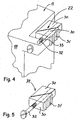
- Fig. 1 illustrates an embodiment for a mounting hole 2 for a PEX-pipe terminal box (Fig. 3) according to the invention, where the mounting hole is made by means of a groove cutting tool - by way of example an angle grinder.
- a groove cutting tool - by way of example an angle grinder.
- two vertical, parallel grooves 4 are cut forming the vertical inside walls 6 of the mounting hole 2
- two horizontal, parallel grooves 8 are cut to form the height of the mounting hole 2.
- the brick or concrete material between the vertical grooves 4 and the horizontal grooves 8 forming the horizontal inside walls 10 is removed by means of a chisel and a hammer, whereby the bottom part 12 of the mounting hole 2 becomes rather rough and uneven.
- a central vertical the groove 14 for the PEX-pipe to be connected to an inlet terminal of the terminal box.
- Fig, 2 shows a known or prior art terminal box 16. From the outer configuration or shape of this it is easy to understand that may be very difficult or time consuming to get this known terminal box 16 correct positioned for wall flush mounting in a mounting hole like the mounting hole 2.
- this terminal box 18 is designed for easy fixation in a mounting hole 2 as shown in Fig. 1.
- the terminal box 18 is at both vertical sides 20 at the corner parties provided with four expansion members 22 being designed to fixation the terminal box 18 alone by engagement with the vertical inside walls 6 of the mounting hole 2.
- the rough and uneven bottom part 12 of the mounting hole 12 has no importance or meaning at all for the correct and easy fixation of the terminal box 18 inside the mounting hole 2.
- the terminal box 18 has a lower inlet terminal 24 for an inlet PEX-pipe connection and an outlet terminal 26 for the connection to a valve member or the like of a water installation.
- the expansion members 22 may be easily operated from a front side 28 of the terminal box 18 by means of a simple screw driver.
- each of the expansion members 22 comprises two wedges 30 of similar slope arranged such that the thin end of the wedges 30 overlies, and that both wedges 30 are interconnected by means of a through-going screw 32 available for operation from the front side 28 of the terminal box 18.
- a through-going screw 32 available for operation from the front side 28 of the terminal box 18.
- the expansion member 22 is connected or integrated with the terminal box 18 by means of a thin, flexible wall part 33 extending between the outermost wedge 30 and the corner part of the front side 28 of the terminal box 18.
- the loose expansion members 34 may be provided with attachment means for quick and easy connection to the outside walls of a known terminal box similar to that terminal box 16 shown in Fig. 2.
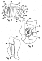
- Figs. 6-8 show a known terminal box 36 during the fixation/mounting in a mounting hole 38 by means of a pair of loose expansion members 40 according to the present invention.
- Fig. 6 is shown how existing lateral protruding, horizontal ribs 42 are used for the receiving of an inner part 44 of the expansion member 40 in such a manner, that a forwardly closed, elongate slot 46, provided in an inner edge of said inner part 44, fits on said rib 42, so that said inner part 44 can be placed on said rib 42 and be fixed behind a circular front part 48 of the terminal box 36.
- said inner part 44 Opposite the elongate slot 46, said inner part 44 has an inclined edge or wedge part 50, along which a loose expansion part 52 may be displaced, as an inner edge part 54 thereof is provided with an elongate slot fitting on said wedge part 50.
- the expansion part 52 is connected to the inner part 44 by means of a screw 56, which may be operated from the front side of the terminal box 36 (Fig. 7) by means of a screwdriver in order to activate the expansion members 40 by displacement of the expansion part 52 along the wedge part 50.
- a screw 56 which may be operated from the front side of the terminal box 36 (Fig. 7) by means of a screwdriver in order to activate the expansion members 40 by displacement of the expansion part 52 along the wedge part 50.
- the expansion part 52 has a corrugated edge surface 58 adapted to engage with an inside, verti-cal wall part of the mounting hole 38.
- the width of which should be about 70 mm, while the depth of the mounting hole 38 should be about 45 mm.
- the expansion member according to the invention may utilize any type of expansion system - by way of example the expansion member may consist of an oval or eccentric member being attached to the respective outsides of the terminal box and being adapted to be turned from the front side thereof by means of a tool engaging in a notch or the like.
- the expansion members may consist of pieces of flexible tube being attached to the opposite outsides of the terminal box and being provided with a cone-shaped member adapted to be forced into said pieces of flexible tube for the fixation of the terminal box against the predominantly vertical inside walls of a mounting hole with said inside walls furthermore being predominantly parallel.
- expansion principle according to the invention using either loose expansion members 34 or integrated expansion members 22 may be used more generally for the purpose of fixation of other types of boxes, mountings and the like between two predominantly vertical or horizontal sides or surfaces.
Landscapes
- Health & Medical Sciences (AREA)
- Life Sciences & Earth Sciences (AREA)
- Engineering & Computer Science (AREA)
- Hydrology & Water Resources (AREA)
- Public Health (AREA)
- Water Supply & Treatment (AREA)
- Connection Or Junction Boxes (AREA)
Abstract

Description
- The present invention relates to a terminal box for water installation and of the type indicated in the preamble of claim 1.
- The invention also relates to an expansion member for use - by way of example - in connection with a terminal box for wall flush mounting for water installation.
- For water installations as well as for heating installations which is build-in in brick or concrete walls is often made use of PEX-pipes in connection with special terminal boxes.
- During the preparation of the building-in of a terminal box for hidden water installation a rectangular mounting hole is cut the brick wall or concrete wall by means of a cutting tool and a chisel. Normally the rectangular hole is made by cutting two mutually parallel vertical grooves and two mutually horizontal grooves in such a way that the distances between the respective vertical and horizontal grooves determine the width and the height of the hole, Then the central part of the brick wall between the grooves is removed by mean of a chisel and a hammer. Hereby is made a hole with smote sides, however the bottom part of the hole is rather rough and uneven, which means that it can be rather difficult to fix the terminal box inside the hole in a correct position.
- In order to be able to fix such terminal boxes in correct position in relation to the wall surface, it is known to provide the terminal box with a special external fixation bar adapted to be fastened to the wall surface at opposite sides of the mounting hole by screws. In other words one have to marked up and to drill holes for screw plugs in correct positions and such works may be rather time consuming. Another disadvantage is that the subsequent plaster work for building-in the terminal box is made difficult by the presence of the fixing bar.
- On that background it is the purpose of the invention to provide a new and improves terminal box of the introductory indicated type, by means of which it will be possibly to obtain a more easier and quicker fixation of the terminal box in correct position in the mounting hole, without the need of using any external fixing bar or the like.
- The terminal box according to the invention is characterized in being provided with a number of expansion members, by means of which said terminal box may be fixed in a mounting hole provided in a brick wall or a concrete wall. By simple provisions is hereby obtained a new and improved terminal box by means of which it will be possibly to obtain a more easier and quicker fixation of the terminal box in correct position in the mounting hole, without the need of using any external fixing bar or the like.
- Appropriately, the terminal box according to the invention may be such adapted, that it is provided with one of said expansion members at opposite sides.
- Advantageously, the terminal box according to the invention may be such adapted, that it is provided with two of said expansion members at opposite sides.
- The terminal box according to the invention may furthermore be such adapted, that the expansion members are integrated with said terminal box at opposite sides thereof.
- With particular advantages the terminal box according to the invention may be such provided, that each of said expansion members comprises two wedges of similar slope arranged such that the thin end of the wedges overlies, and that both wedges are interconnected by means of a screw available for operation from the front side of the terminal box.
- Appropriately, the terminal box according to the invention is such adapted, that the outermost of said wedges is provided with a corrugated surface for engagement against an inside of a said mounting hole.
- In order to integrate said expansion members with the terminal box according to the invention it may appropriately be such provided, that the outermost of said wedges is connected to a front part of said terminal box by means of a flexible, thin wall part.
- The invention also relates to an expansion member for use - by way of example - in connection with a terminal box for wall flush mounting for water installation.
- The expansion member according to the invention is characterized in; that it comprises two wedges of similar slope arranged such that the thin end of the wedges overlies, and that both wedges are interconnected by means of a screw available for operation from the front side of the outermost wedge.
- Appropriately, the expansion member according to the invention may be such adapted, that the outermost of said wedges is provided with a corrugated surface for engagement against by way of example an inside of a mounting hole.
- Furthermore the expansion member according to the invention may be such provided, that each wedge having a retaining means preferable in the form of a dovetail rib and groove - as by way of example disclosed in
GB-A-2404388 - The invention is described in more details in the following with reference to the accompanying drawing, in which:-
- Fig. 1
- shows a perspective view of an embodiment for a mounting hole for a terminal box according to the invention as provided in a brick wall or concrete wall,
- Fig. 2
- shows a perspective view of a known PEX-pipe terminal box for wall flush mounting for water or heating installation,
- Fig. 3
- shows a perspective view of an embodiment for a terminal box according to the invention,
- Fig. 4
- shows an enlarged perspective view of an upper corner part of the terminal box shown in Fig. 2,
- Fig. 5
- shows a perspective view of an embodiment for a loose expansion member according to the invention,
- Fig. 6
- shows a perspective view of another embodiment for a terminal box being provided with another embodiment for expansion members according to the invention - seen from the top side of the terminal box,
- Fig. 7
- shows a perspective view of a terminal box cf. Fig. 6 during the fixation in a mounting hole in a wall, and
- Fig. 8
- shows the terminal box cf. Fig. 6 after the fixation/mounting in the wall.
- Fig. 1 illustrates an embodiment for a
mounting hole 2 for a PEX-pipe terminal box (Fig. 3) according to the invention, where the mounting hole is made by means of a groove cutting tool - by way of example an angle grinder. With mutual distance two vertical,parallel grooves 4 are cut forming the vertical inside walls 6 of themounting hole 2, while two horizontal, parallel grooves 8 are cut to form the height of themounting hole 2. Afterwards the brick or concrete material between thevertical grooves 4 and the horizontal grooves 8 forming the horizontal inside walls 10 is removed by means of a chisel and a hammer, whereby the bottom part 12 of themounting hole 2 becomes rather rough and uneven. Finally at the lower horizontal inside wall 10 is cut a central vertical thegroove 14 for the PEX-pipe to be connected to an inlet terminal of the terminal box. - Fig, 2 shows a known or prior
art terminal box 16. From the outer configuration or shape of this it is easy to understand that may be very difficult or time consuming to get this knownterminal box 16 correct positioned for wall flush mounting in a mounting hole like themounting hole 2. - Otherwise, by the embodiment for a
terminal box 18 shown in Fig. 3, it is easy to understand, that thisterminal box 18 is designed for easy fixation in amounting hole 2 as shown in Fig. 1. For that purpose theterminal box 18 is at bothvertical sides 20 at the corner parties provided with fourexpansion members 22 being designed to fixation theterminal box 18 alone by engagement with the vertical inside walls 6 of themounting hole 2. In other words the rough and uneven bottom part 12 of the mounting hole 12 has no importance or meaning at all for the correct and easy fixation of theterminal box 18 inside themounting hole 2. - The
terminal box 18 has alower inlet terminal 24 for an inlet PEX-pipe connection and an outlet terminal 26 for the connection to a valve member or the like of a water installation. As seen more clearly in Fig. 4 theexpansion members 22 may be easily operated from afront side 28 of theterminal box 18 by means of a simple screw driver. - Fig. 4 shows in details that each of the
expansion members 22 comprises twowedges 30 of similar slope arranged such that the thin end of thewedges 30 overlies, and that bothwedges 30 are interconnected by means of a through-goingscrew 32 available for operation from thefront side 28 of theterminal box 18. When turning thescrew 32 clockwise, thewedges 30 are engaging more and more with each other and the width of theexpansion member 22 is increased until safe engagement against the vertical inside walls 6 is achieved and theterminal box 18 is positioned in correct fixation within themounting hole 2. Theoutermost wedge 30 is provided with acorrugated surface 31 for engagement against by way of example an inside of a mounting hole. - As furthermore shown in Fig. 4 the
expansion member 22 is connected or integrated with theterminal box 18 by means of a thin,flexible wall part 33 extending between theoutermost wedge 30 and the corner part of thefront side 28 of theterminal box 18. - During the development of the
terminal box 18 according to the invention it was decided also to provide forloose expansion members 34 as shown in Fig. 5, so that in a transition period untilterminal boxes 18 with integratedexpansion members 22 are available in the market, the fixation principle according to the invention may be used for the fixation byloose expansion members 34. And therefore the saidloose expansion members 34 being a part of the present invention. - The
loose expansion members 34 may be provided with attachment means for quick and easy connection to the outside walls of a known terminal box similar to thatterminal box 16 shown in Fig. 2. - Figs. 6-8 show a
known terminal box 36 during the fixation/mounting in a mountinghole 38 by means of a pair ofloose expansion members 40 according to the present invention. In Fig. 6 is shown how existing lateral protruding,horizontal ribs 42 are used for the receiving of aninner part 44 of theexpansion member 40 in such a manner, that a forwardly closed,elongate slot 46, provided in an inner edge of saidinner part 44, fits on saidrib 42, so that saidinner part 44 can be placed on saidrib 42 and be fixed behind a circularfront part 48 of theterminal box 36. Opposite theelongate slot 46, saidinner part 44 has an inclined edge orwedge part 50, along which aloose expansion part 52 may be displaced, as aninner edge part 54 thereof is provided with an elongate slot fitting on saidwedge part 50. - The
expansion part 52 is connected to theinner part 44 by means of ascrew 56, which may be operated from the front side of the terminal box 36 (Fig. 7) by means of a screwdriver in order to activate theexpansion members 40 by displacement of theexpansion part 52 along thewedge part 50. Opposite saidinner edge part 54 theexpansion part 52 has acorrugated edge surface 58 adapted to engage with an inside, verti-cal wall part of the mountinghole 38. The width of which should be about 70 mm, while the depth of the mountinghole 38 should be about 45 mm. - The expansion member according to the invention may utilize any type of expansion system - by way of example the expansion member may consist of an oval or eccentric member being attached to the respective outsides of the terminal box and being adapted to be turned from the front side thereof by means of a tool engaging in a notch or the like.
- Otherwise the expansion members may consist of pieces of flexible tube being attached to the opposite outsides of the terminal box and being provided with a cone-shaped member adapted to be forced into said pieces of flexible tube for the fixation of the terminal box against the predominantly vertical inside walls of a mounting hole with said inside walls furthermore being predominantly parallel.
- Even for temporary fixation of door and/or window frames in the construction sector use may be made of either loose expansion members or integrated expansion members according to the present invention.
- Finally it should be mentioned that the expansion principle according to the invention using either
loose expansion members 34 orintegrated expansion members 22 may be used more generally for the purpose of fixation of other types of boxes, mountings and the like between two predominantly vertical or horizontal sides or surfaces.
Claims (10)
- A terminal box (18) for water installation and of the type being adapted for wall flush mounting and comprising at least one inlet terminal (24) for a PEX-pipe and at least one outlet terminal (26) for a water tap or the like, characterized in being provided with a number of expansion members (22), by means of which said terminal box (18) may be fixed in a mounting hole (2) provided in a brick wall or a concrete wall.
- A terminal box according to claim 1, characterized in, that it is provided with one of said expansion members (22) at opposite sides.
- A terminal box (18) according to claim 1, characterized in, that it is provided with two of said expansion members (22) at opposite sides.
- A terminal box (18) according to claim 1, characterized in, that the expansion members (22) are integrated with said terminal box (18) at opposite sides thereof.
- A terminal box (18) according to any of the preceding claims, characterized in, that each of said expansion members (22) comprises two wedges (30) of similar slope arranged such that the thin end of the wedges (30) overlies, and that both wedges (30) are interconnected by means of a screw (32) available for operation from the front side of the terminal box (18).
- A terminal box (18) according to claim 5, characterized in, that the outermost of said wedges (30) is provided with a corrugated surface (31) for engagement against an inside of a said mounting hole (2).
- A terminal box (18) according to claim 5, characterized in, that the outermost of said wedges (30) is connected to a front part of said terminal box (18) by means of a flexible, thin wall part (33).
- An expansion member (34) for use - by way of example - in connection with a terminal box for wall flush mounting for water installation, characterized in, that it comprises two wedges (30) of similar slope arranged such that the thin end of the wedges (30) overlies; and that both wedges (30) are interconnected by means of a screw (32) available for operation from the front side of the outermost wedge.
- An expansion member (34) according to claim 8, characterized in, that the outer-most of said wedges (30) is provided with a corrugated surface (31) for engagement against by way of example an inside of a mounting hole (2).
- An expansion member according to claim 8, characterized in, that each wedge having a retaining means preferable in the form of a dovetail rib and groove.
Applications Claiming Priority (1)
| Application Number | Priority Date | Filing Date | Title |
|---|---|---|---|
| DKPA200501270 | 2005-09-12 |
Publications (1)
| Publication Number | Publication Date |
|---|---|
| EP1762661A1 true EP1762661A1 (en) | 2007-03-14 |
Family
ID=37459541
Family Applications (1)
| Application Number | Title | Priority Date | Filing Date |
|---|---|---|---|
| EP06019081A Withdrawn EP1762661A1 (en) | 2005-09-12 | 2006-09-12 | Terminal box for water installation and an expansion member therefore |
Country Status (1)
| Country | Link |
|---|---|
| EP (1) | EP1762661A1 (en) |
Citations (11)
| Publication number | Priority date | Publication date | Assignee | Title |
|---|---|---|---|---|
| EP0085329A2 (en) * | 1982-01-29 | 1983-08-10 | Georg Fischer Aktiengesellschaft | Connecting device for taps |
| US4804171A (en) * | 1987-11-06 | 1989-02-14 | Dornfeld Stanley W | Workpiece holding device |
| DE8815170U1 (en) * | 1988-12-06 | 1989-03-23 | Huang, Jue Ping, Hsin-Chuang, Taipei | Adjustable mounting gauge |
| US5797573A (en) * | 1995-01-12 | 1998-08-25 | The Boeing Company | Non-penetration clip attachment |
| DE19715651A1 (en) * | 1997-04-15 | 1998-10-22 | Ortwein Ernst Georg | Connection arrangement for water supply and drainage with sound and thermal insulation |
| US5983923A (en) * | 1996-04-10 | 1999-11-16 | Lsp Products Group, Inc. | Water service box and connectors for PEX pipe |
| DE10035883A1 (en) * | 1999-07-23 | 2001-05-17 | Kirchner Fraenk Rohr | Mounting rail for shower mixer |
| WO2001048326A1 (en) * | 1999-12-17 | 2001-07-05 | Tom Christensen | Lead-through device for a pipeline in a building element e.g. a wall and a procedure for such a lead-through |
| DE10053668C1 (en) * | 2000-10-28 | 2002-07-11 | Robert K Wahl | Clamp for clamping objects against fixed surface consists of two wedge units movable along slide surfaces, screw in hole, with nut enabling wedge units to slide and form parallelepiped divided along diagonal surface |
| GB2404388A (en) | 2003-07-26 | 2005-02-02 | Toby Richard Treacher | A wedging device for securing lead flashing in a slot between two adjacent rows of brickwork |
| DE102004005161A1 (en) * | 2004-02-02 | 2005-08-18 | Grohe Water Technology Ag & Co. Kg | Mounting system for sanitary fitting in bathroom has rectangular frame sunk into wall and has connections for hot and cold water regulating taps and has wire with electrical connections |
-
2006
- 2006-09-12 EP EP06019081A patent/EP1762661A1/en not_active Withdrawn
Patent Citations (11)
| Publication number | Priority date | Publication date | Assignee | Title |
|---|---|---|---|---|
| EP0085329A2 (en) * | 1982-01-29 | 1983-08-10 | Georg Fischer Aktiengesellschaft | Connecting device for taps |
| US4804171A (en) * | 1987-11-06 | 1989-02-14 | Dornfeld Stanley W | Workpiece holding device |
| DE8815170U1 (en) * | 1988-12-06 | 1989-03-23 | Huang, Jue Ping, Hsin-Chuang, Taipei | Adjustable mounting gauge |
| US5797573A (en) * | 1995-01-12 | 1998-08-25 | The Boeing Company | Non-penetration clip attachment |
| US5983923A (en) * | 1996-04-10 | 1999-11-16 | Lsp Products Group, Inc. | Water service box and connectors for PEX pipe |
| DE19715651A1 (en) * | 1997-04-15 | 1998-10-22 | Ortwein Ernst Georg | Connection arrangement for water supply and drainage with sound and thermal insulation |
| DE10035883A1 (en) * | 1999-07-23 | 2001-05-17 | Kirchner Fraenk Rohr | Mounting rail for shower mixer |
| WO2001048326A1 (en) * | 1999-12-17 | 2001-07-05 | Tom Christensen | Lead-through device for a pipeline in a building element e.g. a wall and a procedure for such a lead-through |
| DE10053668C1 (en) * | 2000-10-28 | 2002-07-11 | Robert K Wahl | Clamp for clamping objects against fixed surface consists of two wedge units movable along slide surfaces, screw in hole, with nut enabling wedge units to slide and form parallelepiped divided along diagonal surface |
| GB2404388A (en) | 2003-07-26 | 2005-02-02 | Toby Richard Treacher | A wedging device for securing lead flashing in a slot between two adjacent rows of brickwork |
| DE102004005161A1 (en) * | 2004-02-02 | 2005-08-18 | Grohe Water Technology Ag & Co. Kg | Mounting system for sanitary fitting in bathroom has rectangular frame sunk into wall and has connections for hot and cold water regulating taps and has wire with electrical connections |
Similar Documents
| Publication | Publication Date | Title |
|---|---|---|
| EP2093362B1 (en) | Method and clamping system for the fixation of a hinge or other metal work on profiles for windows and doors | |
| EP1762661A1 (en) | Terminal box for water installation and an expansion member therefore | |
| CA2205164C (en) | Door frame | |
| JP2007239229A (en) | Structure for mounting opening frame in skeleton | |
| EP1722063A2 (en) | Adjustable frame device | |
| KR20090003586U (en) | A construction pannel and instullation device | |
| SK3698A3 (en) | Mounting for longitudinally grooved cover mouldings | |
| EP0236287A2 (en) | A door arrangement | |
| KR20180126875A (en) | soundproof walls | |
| KR20230003704A (en) | Wedge Anchor Assembly at Face of Exterior Wall | |
| KR200224301Y1 (en) | Board material anchor for building | |
| GB2144591A (en) | Fitting an outlet box | |
| KR200418941Y1 (en) | Support wedge for windows frame fixing | |
| KR20090003227U (en) | Crime prevention window | |
| NO180688B (en) | Plug | |
| KR200294096Y1 (en) | Structure for assembling end cover | |
| AU2006225315B2 (en) | End fitting for an extrusion and fixing method | |
| KR100805860B1 (en) | Anchor combined material installation device | |
| EP3096424A1 (en) | Flexible claw grip for fastening an element in a box and element to be fixed by said claw | |
| KR200438907Y1 (en) | Setting block of a windows and doors frame | |
| JP4749264B2 (en) | Indoor lattice mounting mechanism | |
| KR200421788Y1 (en) | The installation structure of in-material panel for construction | |
| JP6249701B2 (en) | Groove construction device | |
| KR200271765Y1 (en) | Wallform fiyed flat tie | |
| KR101981861B1 (en) | Coupling device for file pipes |
Legal Events
| Date | Code | Title | Description |
|---|---|---|---|
| PUAI | Public reference made under article 153(3) epc to a published international application that has entered the european phase |
Free format text: ORIGINAL CODE: 0009012 |
|
| AK | Designated contracting states |
Kind code of ref document: A1 Designated state(s): AT BE BG CH CY CZ DE DK EE ES FI FR GB GR HU IE IS IT LI LT LU LV MC NL PL PT RO SE SI SK TR |
|
| AX | Request for extension of the european patent |
Extension state: AL BA HR MK YU |
|
| 17P | Request for examination filed |
Effective date: 20070908 |
|
| 17Q | First examination report despatched |
Effective date: 20071015 |
|
| AKX | Designation fees paid |
Designated state(s): AT BE BG CH CY CZ DE DK EE ES FI FR GB GR HU IE IS IT LI LT LU LV MC NL PL PT RO SE SI SK TR |
|
| STAA | Information on the status of an ep patent application or granted ep patent |
Free format text: STATUS: THE APPLICATION IS DEEMED TO BE WITHDRAWN |
|
| 18D | Application deemed to be withdrawn |
Effective date: 20100401 |